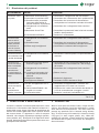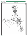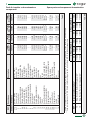
1
SERIE MM1 63-71-80-90-100
Manuale di uso e manutenzione
Use and Maintenance manual
REV00
04/2012
INDICE
CONTENTS
1
INFORMAZIONI SULLA SICUREZZA.................. 4
1
INFORMATION ABOUT SAFETY ....................... 4
2
USO PREVISTO.................................................... 4
2
USE......................................................................... 4
3
TRASPORTO E GIACENZA A MAGAZZINO...... 5
3
TRANSPORTATION AND STORAGE.................. 5
4
4.1
4.2
4.3
INSTALLAZIONE................................................... 6
Fori scarico condensa............................................ 7
Collegamenti, terminali e senso di rotazione........ 7
Messa in servizio.................................................... 8
4
4.1
4.2
4.3
INSTALLATION...................................................... 6
Condensate drain ports.......................................... 7
Cabling, terminals and direction of rotation........... 7
Commissioning....................................................... 8
5
5.1
5.2
5.3
MANUTENZIONE.................................................. 9
Smontaggio e rimontaggio..................................... 9
Cuscinetti................................................................ 10
Risoluzione dei problemi........................................ 11
5
5.1
5.2
5.3
MAINTENANCE..................................................... 9
Disassembly and re-assembly.............................. 9
Bearings.................................................................. 10
Trouble shooting..................................................... 12
6
DEMOLIZIONE E SMALTIMENTO....................... 11 6
DISMANTLING....................................................... 11
7
PARTI DI RICAMBIO E DENOMINAZIONE
7
COMPONENTI....................................................... 12 SPARE PARTS AND COMPONENT
DENOMINATION................................................... 12
8
ALLEGATI............................................................... 13
Collegamenti in morsettiera................................... 15
Disegno esploso....................................................18
Parti di ricambio e denominazione componenti...19
Disegno esploso....................................................20
Parti di ricambio e denominazione componenti...21
RICAMBI ED ASSISTENZA.................................22
GARANZIA............................................................24
Dichiarazione di conformità...................................27
ANNEXES.............................................................. 13
Terminal board connections................................... 15
Exploded view........................................................ 18
Spare parts and component denomination........... 19
Exploded view........................................................ 20
Spare parts and component denomination........... 21
SPARE PARTS AND AFTERSALES.................... 22
WARRANTY........................................................... 24
Declaration of conformity....................................... 27
8
3
1 INFORMAZIONI SULLA SICUREZZA
1 INFORMATION ABOUT SAFETY
Il “Manuale Uso e Manutenzione” accluso al motore
fornisce importanti indicazioni riguardanti la sicurezza,
l’installazione, l’uso e la manutenzione.
Questo manuale di istruzioni è stato redatto sulla base
delle indicazioni fornite dalla Direttiva 2006/95/CE, nota
come “Direttiva Bassa Tensione” e dalla norma IEC
60204-1 (“Equipaggiamento elettrico delle macchine,
sicurezza del macchinario, principi di progettazione,
specifiche e principi tecnici”).
Attenersi scrupolosamente a quanto riportato nel manuale, che ha lo scopo di indicare le corrette condizioni
di installazione e manutenzione, al fine di prevenire
eventuali malfunzionamenti del motore ed evitare situazioni di pericolo per l’utente. Questo prodotto è stato
progettato e costruito esclusivamente per l’utilizzo indicato in questa documentazione. Usi non indicati in questa documentazione potrebbero essere fonte di danni
al prodotto e fonte di pericolo. Sono stati riportati inoltre
tutti i suggerimenti derivanti da esperienze applicative,
necessari per garantire l’uso corretto e sicuro del motore elettrico. Viene richiesto che i fondamentali lavori di
predisposizione dell’impianto, montaggio, installazione,
messa in servizio, manutenzione, vengano eseguiti da
personale qualificato e controllati dal personale tecnico
responsabile.
Le serie di motori elettrici SOGA coperte da questo manuale sono conformi alle seguenti direttive:
-- Direttiva europea 2006/95/CE (“Direttiva Bassa tensione”);
-- Direttiva europea 2004/108/CE (“Direttiva sulla compatibilità elettromagnetica”);
-- Direttiva europea 2002/95/CE (“Direttiva RoHS”);
Le serie di motori elettrici SOGA sono stati progettati
seguendo le norme internazionali IEC 60034 (“Macchine elettriche rotanti”), IEC 60072 e CEI EN 50347
(“Dimensioni e potenze standard”). La verifica della
compatibilità elettromagnetica è stata condotta in base
alle seguenti norme IEC 61000-6-2 e IEC 61000-6-3.
The “User and Maintenance Manual” included with the
motor provides important indications regarding safety,
installation, use and maintenance.
This instruction manual has been compiled in accordance with the dispositions supplied by the Directive
2006/95/EC (“Low Voltage Directive”) and by the IEC
60204-1 standard (“Electrical machine equipment, machinery safety, principles of design, specifications and
technical principles”).
Strictly observe the instructions given in the “User
and Maintenance Manual” that is provided to indicate
the correct conditions for installation, use and maintenance, in order to prevent motor malfunctions and
avoid hazardous situations for the user. This product
has been designed and constructed solely for the application indicated in this manual. Any use not specified
in this manual may cause damage to the product and
become a source of hazard.
Moreover, all the suggestions deriving from application
experience have been included, as these are necessary to guarantee the correct, safe use of electric motors. It is requested that all the basic work of preparing
the plant, assembly, installation, start up and maintenance be carried out by qualified staff and be controlled
by the technical staff responsible for it.
The SOGA motor series covered by this manual comply with the following directives:
-- European Directive 2006/95/EC (“ Low Voltage Directive”);
-- European Directive 2004/108/EC (“Electromagnetic
Compatibility Directive”);
-- European Directive 2002/95/EC (“RoHS Directive”);
The SOGA motor series has been designed to meet the
IEC 60034 standard (“Rotating Electrical Machines”),
IEC 60072 e EN 50347 (“Standard output and frame
sizes”). The following standards were used to evaluate
the elecromagnetic compatibility: IEC 61000-6-2 and
IEC 61000-6-3.
2 USO PREVISTO
2 USE
I motori elettrici della serie MM1 63 - MM1 71 - MM1 80
- MM1 90 - MM1 100 con altezza d’asse compresa tra
63 e 100 sono destinati ad installazioni di tipo industriale e commerciale. I motori della serie MM1 63 - MM1
71 - MM1 80 - MM1 90 - MM1 100 con altezza d’asse
compresa tra 63 e 100, sono trifase del tipo chiuso.
Sulla targhetta sono riportati i seguenti dati: potenza,
tensione, frequenza, corrente e velocità nominali. Se
non diversamente specificato, i modelli sono progettati per temperature ambientali comprese tra –15°C e
+ 40°C e per altitudini non superiori a 1000m s.l.m.. I
valori di rumorosità sono in accordo alla curva A del
fonometro secondo la norma CEI EN 60651. La tabella 8.5 riporta i valori medi della potenza sonora (LwA)
e della pressione sonore (LpA) in dB(A). I valori sono
The motors of the MM1 63 - MM1 71 - MM1 80 - MM1
90 - MM1 100 series, with an axial height range from
63 to 100, are intended for industrial and commercial
installation. The motors of the MM1 63 - MM1 71 - MM1
80 - MM1 90 - MM1 100 series, with an axial height
ranging from 63 to 100, are three-phase closed type
motors.
On the nameplate are shown the following data: nominal power, voltage, frequency, current and speed.
Unless otherwise specified, models are designed for
ambient temperatures between -15°C to + 40°C and
altitudes up to 1000 m.a.s.l. The noise level is determined in accordance with curve A of the sound level
meter as per EN 60651. Table 8.5 shows the average
values of sound power level (LwA) and pressure level
4
stati rilevati con motore funzionante a vuoto, alimentato
alla tensione nominale a 50Hz. La tolleranza è pari a
3 dB(A).
I motori, se non diversamente specificato, sono protetti
secondo il grado IP54 della norma IEC 60034-5.
Per condizioni ambientali diverse da quelle sopraindicate, la potenza nominale del motore varia. In questo
caso è necessario applicare i fattori correttivi indicati
nella tabella 8.4. Su richiesta si eseguono trattamenti speciali per ambienti particolarmente corrosivi e ad
elevata umidità.
Per temperature maggiori di 40°C e per ambienti con
temperature costantemente inferiori ai -15°C è consigliabile consultare di volta in volta i nostri Uffici Tecnici.
Per sovraccarichi, servizi di durata limitata o per servizi
intermittenti con frequenti avviamenti occorre interpellare il nostro Ufficio Tecnico fornendo le informazioni
riguardo il tipo di servizio, il numero degli avviamenti
orari, l’inerzia delle masse accoppiate al motore.
L’eccessivo riscaldamento del motore per sovraccarichi, avviamenti o frenature prolungate o per mancanza
di una fase di rete, viene evitato con l’impiego di un
appropriato salvamotore. Per aumentare la sicurezza
di funzionamento in presenza di servizi particolarmente gravosi, si possono installare negli avvolgimenti dei
particolari sensori termici. Su richiesta vengono forniti
motori provvisti di: dispositivi di avviamento, interruttore
magnetotermico con relè di sgancio di minima tensione, protettori termici, termistori, termorilevatori, scaldiglie anticondensa.
IMPORTANTE!
I fusibili non costituiscono una protezione per il motore, bensì solo una
protezione contro i cortocircuiti.
(LpA) in dB(A). These values are measured with the
motor running at no load, rated voltage and 50Hz. The
tolerance is 3 dB(A).
If not otherwise specified, the motors are supplied with
IP54 protection class, according to IEC 60034-5 standard.
For environmental conditions different from the above
mentioned ones, the power varies and it is obtained by
applying the correcting factors indicated in table 8.4.
Special treatments for particular corrosive environments and those with high humidity are available on
request.
For temperatures over 40°C and for environments with
temperatures constantly below -15°C, it is advisable to
contact our Technical Office. For overloads, services
of limited duration or for intermittent duty with frequent
start-ups it is necessary to contact us and give the information on the type of duty, the number of start-ups
every hour and the inertia of the masses connected to
the motor.
Excessive heating of the motor due to overloading,
prolonged starting up, braking or power failure can be
avoided by using an adequate overload relay (on request). Special thermal sensors can be installed in the
windings for a higher operational safety with particularly
heavy duty. On request we can supply motors provided
with starting devices, magneto-thermal switches with
triggering relay for minimum voltage, thermal switches,
thermistors, thermal detectors, anti-condensation heaters.
IMPORTANT!
Fuses do not provide protection for
the motor, but only protection against
short circuits.
3 TRASPORTO E GIACENZA A
MAGAZZINO
3 TRANSPORTATION AND STORAGE
All’arrivo a destinazione esaminare il motore accuratamente onde verificare che non abbia subito danni durante il trasporto. Eventuali danni visibili devono essere
denunciati subito al trasportatore.
Se il motore non viene posto immediatamente in servizio, dovrà essere immagazzinato in un luogo coperto,
pulito, asciutto e privo di vibrazioni. Il peso del motore
lo si può leggere nei dati di targa.
Dopo quattro anni dalla fornitura e con un immagazzinamento in condizioni favorevoli è consigliabile sostituire i cuscinetti e controllare che la resistenza di isolamento sia superiore a 10 MΩ. In condizioni sfavorevoli
tale tempo si dimezza.
Upon arrival, carefully examine the motor to check
whether it has been damaged during transportation.
Any visible damage should be immediately reported to
the carrier.
If the motor is not immediately commissioned, it should
be stored in a sheltered, clean and dry place, free of vibrations. The motor weight is shown on the nameplate.
After four years from the date of supply, and with the
motor stored in good conditions, it is advisable to replace the bearings and check if the insulation resistance is higher than 10 MΩ. Under unfavourable storage conditions, this check-time is reduced by half.
5
4 INSTALLAZIONE
4 INSTALLATION
Prima di procedere con l’installazione controllare che
i dati di targa siano adeguati alle caratteristiche della
macchina e del luogo dove si sta assemblando il motore. Il motore elettrico è un componente che viene
meccanicamente accoppiato ad un’altra macchina singola o costituente parte di un impianto ed è pertanto
responsabilità di chi esegue l’installazione garantire la
conformità a tutte le prescrizioni e le raccomandazioni
delle norme IEC 60204-1 sull’equipaggiamento elettrico delle macchine.
Per accertare la rispondenza alle specifiche di progetto, durante il ciclo di produzione e al collaudo finale, il
motore viene sottoposto ad accurati controlli di qualità.
Il motore esce dalla fabbrica pronto per l’installazione.
Installare il motore in modo da prevedere la possibilità
di ispezioni e manutenzioni durante il funzionamento,
in ambiente aerato, lontano da fonti di calore. Evitare
che la vicinanza di ostacoli impedisca la ventilazione e
che l’aria calda in uscita sia di nuovo aspirata.
L’eventuale basamento del motore deve essere piano,
robusto in modo d’assorbire le vibrazioni, sufficientemente rigido da mantenere l’allineamento.
Il motore deve essere sempre ben installato, soprattutto se accoppiato direttamente alla macchina condotta.
In caso di vibrazioni eccessive o guasti dei cuscinetti
controllare immediatamente l’allineamento che potrebbe risultare disassato. La trasmissione di potenza
alla macchina operatrice può avvenire tramite accoppiamento diretto, cinghie di trasmissione, ingranaggi,
etc. Nel caso di accoppiamento diretto si deve usare
un giunto elastico o un giunto flessibile che eviti la trasmissione di eventuali spinte assiali ai cuscinetti. Nel
caso di accoppiamento con cinghie di trasmissione,
installare il motore con l’albero parallelo a quello della
macchina condotta e su di un tendicinghia per poter
regolare la tensione delle cinghie. Tenere ben presente
che una tensione eccessiva è nociva alla durata dei
cuscinetti e, nei casi più gravi, può provocare la rottura
dell’albero.
Before proceeding with the installation, check that the
data shown on the nameplate are adequate to the characteristics of the machine and the site where the motor
is to be installed. The electric motor is a component
which is mechanically connected to another single machine or a machine which is part of a plant and it is,
therefore, responsibility of the installer to guarantee
compliance with all the dispositions and recommendations of the Regulations IEC 60204-1 regarding the
electrical equipment of machinery.
To verify the compliance with the project specifications,
during the production process and the final testing, the
motor is subjected to accurate quality controls. The motor leaves our factory ready for installation.
Provide the possibility of inspection and maintenance
during its operation. Install the motor in an aerated
room, far from heating sources. Make sure that near
obstacles do not avert ventilation and that hot air coming out is sucked again.
If the motor is installed on a basement, it should be flat,
strong enough to absorb vibrations and rigid enough to
maintain alignment.
The motor should always be well installed, above all
if coupled directly with the driven machine. In case of
excessive vibrations or damage of the bearings, check
the alignment at once as the motor could be misaligned. Power transmission to the drive machine can
be done by direct coupling, transmission belts, gears,
etc. In case of direct connection, an elastic coupling or
a flexible coupling should be used to avoid the transmission of any axial thrusts to the bearings. In case of
coupling by transmission belts, install the motor with
the shaft parallel to that of the driven machine and on
a belt tightening pulley to adjust belt tension. Keep in
mind that the excessive tension is harmful to bearings
life and, in the worst case, could cause the breaking of
the shaft.
IMPORTANTE!
Non superare mai i carichi assiali e
radiali massimi consentiti e in caso
di dubbi interpellare il nostro Ufficio
Tecnico (vedi tabelle 8.1 e 8.2).
Salvo diversa indicazione, il rotore è equilibrato dinamicamente con mezza linguetta. Anche gli organi di
trasmissione devono essere accuratamente bilanciati prima del montaggio. Il montaggio e lo smontaggio
degli organi di accoppiamento e dei cuscinetti devono
essere eseguiti da personale qualificato con modalità e
attrezzi adatti allo scopo.
Prima della messa in servizio verificare che la resistenza d’isolamento non sia inferiore a 10 MΩ. Per macchine che hanno già lavorato per lunghi periodi di tempo si
deve verificare che la resistenza d’isolamento dell’av-
6
IMPORTANT!
Never exceed the maximum axial and
radial loads allowed and, when in
doubt, consult our Technical Office.
(See tables 8.1 and 8.2).
Unless otherwise specified, the rotor is balanced dynamically by half a key; also the transmission organs
should be carefully balanced before assembly. Assembly and disassembly of the coupling organs and the
bearings should be carried out by qualified personnel
only and using adequate tools.
At first commissioning, check that the insulation resistance is not lower than 10 MΩ. The insulation resistance of windings that have operated for long period of
time should be over 1 MΩ (the values refer to a room
temperature of 25°C and a dc voltage of 500V). Lower
volgimento non sia inferiore a 1 MΩ (i valori sono riferiti
ad una temperatura ambiente di 25°C applicando una
tensione continua di 500 V). Se il valore della resistenza d’isolamento è inferiore, l’avvolgimento presenta
una eccessiva e pericolosa umidità per cui è necessario essiccarlo ricorrendo ad una ditta specializzata.
Il collegamento elettrico viene eseguito a macchina ferma, con impianto di alimentazione scollegato dalla rete
elettrica, rispettando scrupolosamente le istruzioni di
sicurezza precisate nella norma CEI EN 60204-1.
values indicate that the winding has excessive, dangerous humidity and should be dried by a specialised
company.
Electrical connection should be carried out with the machine at standstill, disconnected from the power grid, in
strict compliance with the safety standards given in the
IEC 60204-1.
4.1 Fori scarico condensa
4.1 Condensate drain ports
Se il motore è provvisto di foro scarico condensa
chiuso da un tappo a vite, procedere periodicamente
allo scarico della condensa (da effettuarsi con motore
spento). In certe condizioni, e comunque non in zone di
pericolo, può essere opportuno eliminare gli eventuali
tappi di chiusura. Il grado di protezione del motore senza tappi di chiusura risulta diminuito.
Taluni motori di produzione SOGA hanno un tappo sullo
scarico condensa di colore verde. Tale tappo ha delle fessure capillari che permettono la fuoriuscita della
condensa senza diminuirne il grado di protezione. Anche in questo caso si consiglia comunque di togliere
periodicamente il tappo e pulirlo con dell’aria compressa onde evitare che particelle di sporco chiudano i condotti capillari di scarico.
If the motor is provided with condensate drain ports
closed with a screw cap, periodically drain the condensate (this operation has to be carried out with the motor at standstill). In certain conditions, but not in danger
areas, it might be suitable to remove the closing caps.
The protection level of the motor without closing caps
is reduced.
Some motors manufactured by SOGA are provided
with a green condensate drain cap. This cap has capillary slots which allow the exit of condensate without
reducing the protection level. Even in this case, it is recommended to remove periodically the cap and clean it
with compressed air so as to avoid that dirt clogs the
drain capillary ducts.
4.2 Collegamenti, terminali e senso di
rotazione
4.2 Cabling, terminals and direction of
rotation
Il collegamento all’alimentazione dovrà avvenire con le
indicazioni riportate sullo schema posto all’interno del
copribasetta o presente in questo manuale.
Connection to the power supply should be carried out
following indications shown in the wiring diagram inside
the terminal strip cover or given in this manual.
Collegare il conduttore di messa a terra sul morsetto
con il simbolo:
Earthing is to be carried out to the terminal with the corresponding symbol:
AVVERTENZA!
Per il collegamento a massa fare riferimento a quanto previsto dalle
norme locali in materia. Collegamenti
a massa o di protezione eseguiti in
modo errato possono portare a gravi
lesioni o al decesso.
Le superfici di contatto devono essere pulite e protette
dalla corrosione.
Il senso di rotazione dipende dal tipo di motore e dal
collegamento in morsettiera. Per maggiori informazioni
andare al paragrafo “Collegamenti in morsettiera” oppure contattare l’Ufficio Tecnico.
Alcuni modelli sono provvisti di interruttori con bobina
di sgancio di minima tensione (a richiesta). Nel caso in
cui la tensione di linea sia molto inferiore al suo valore
nominale l’interruttore rimane in posizione off.
WARNING!
Follow the local regulations on earthing for the ground connection. An inefficient earth connection can cause
injury or death.
Contact surfaces should be clean and protected
against corrosion.
The rotation direction depends on the motor type and
the wiring diagram. For more information see the paragraph “Terminal board connections” or contact the
Technical Department.
Some motor types are provided with minimum voltage
relay (on request). When the line voltage is much lower
than the nominal voltage the switch remains in the off
position.
7
IMPORTANTE!
Impiegare cavi di alimentazione
aventi sezione adeguata a sopportare
la corrente assorbita dal motore evitando sovrariscaldamenti e cadute di
tensione eccessive.
IMPORTANT!
Use power supply cables which have
an adequate cross-section to bear the
current consumption of the motor thus
avoiding overheating and/or power failure.
Impedire che i cavi trasmettano sollecitazioni meccaniche ai morsetti del motore. Al termine di tutte le connessioni, assicurarsi che pressacavi e coprimorsettiera
siano ben chiusi per garantire il massimo grado di protezione. Controllare che l’albero ruoti liberamente.
Effettuare l’inserzione del motore in linea tramite un
dispositivo di protezione. Il dispositivo di protezione
del motore non deve scattare a causa della corrente
di avviamento.
Per avere maggiore coppia di spunto alcuni motori sono
dotati di disgiuntore e condensatore di avviamento.
Allacciamento degli ausiliari (se presenti)
Prevent the cables from transmitting mechanical stress
to the motor terminals and, having carried out all connections, make sure that the cable glands and the terminal box cover are well closed so as to have maximum
protection. Check that the shaft rotates freely.
Connect the motor by means of a protection device.
The protection device must not be activated by the motor start-up current.
-- Protezioni termiche: verificare il tipo di protezione
termica installata prima di effettuare il collegamento; per i termistori è necessario un apposito relè di
sgancio. Alcuni motori, su richiesta, sono provvisti
di protezione termica più interruttore.
-- Resistenze anticondensa: le resistenze anticondensa (scaldiglie) devono essere alimentate
da linee separate e dotate di protezioni proprie.
La tensione di alimentazione si trova in targa. Non
devono assolutamente essere alimentate con il
motore in funzione.
-- Ventilazione ausiliaria: collegare separatamente
il motore dell’elettroventilatore dal motore principale. Predisporre un dispositivo che consenta
l’avviamento del motore principale solo quando il
ventilatore ausiliario è in funzione.
-- Thermal protection: before carrying out connections, check the type of thermal protection installed; for thermistors a special release relay is
necessary. Some motors, on request, are provided
with thermal protection and switch.
-- Anti-condensation resistances: the anti-condensation resistances (heaters) should be powered
with separate power lines and special protections.
Power supply voltage is shown on the nameplate.
These resistances must never be powered when
the motor is operating.
-- Auxiliary fan: connect the electric fan separately
from the motor terminals. Provide a device which
allows the motor start-up only when the auxiliary
fan is activated.
To have a higher starting torque, some motors are
equipped with centrifugal switch and starting capacitor.
Connection to the auxiliary devices (if provided)
4.3 Messa in servizio
4.3 Commissioning
Prima della messa in servizio verificare l’allineamento
con gli organi accoppiati, le connessioni e il collegamento per la messa a terra.
Verificare che siano state chiuse le protezioni degli
organi in movimento, che l’ingresso dell’aria sia libero
e che l’albero ruoti liberamente. Eseguire dunque una
prova funzionale per verificare la rotazione. Se il motore è stato immagazzinato per un periodo che supera i 3
anni è consigliabile cambiare il grasso dei cuscinetti o
sostituirli se del tipo auto lubrificato.
Before commissioning, check the correct alignment of
the coupled elements, as well as the correct connections and earthing. Make sure the protections of live
components are closed, that the air inlet is free from
obstructions and the shaft turns smoothly.
Perform an operating test to check rotation. If the motor
has been stored for a period longer than 3 years, it is
advisable to change the bearing grease or replace the
bearings if they are self-lubricating type.
8
5 MANUTENZIONE
AVVERTENZA!
AVVERTENZA!
AVVERTENZA!
Qualsiasi intervento sul motore deve
essere effettuato a macchina ferma e
scollegata dalla rete di alimentazione. (Compresi i circuiti ausiliari come
le resistenze anticondensa).
Non utilizzare in alcuna occasione
liquidi o acqua. Non pulire con aria
compressa le parti elettriche interne
perché potrebbero verificarsi cortocircuiti o altre anomalie.
Non toccare il motore durante il funzionamento e subito dopo l’arresto
del gruppo in quanto vi potrebbero
essere superfici a temperatura elevata.
5 MAINTENANCE
WARNING!
WARNING!
WARNING!
Any operation to the motor must be
carried out with machine at standstill
and disconnected from the power grid.
(Included the auxiliary circuits such as
anti-condensation resistances).
Never and for no reason whatsoever
use fluids or water. Do not use compressed air to clean internal electrical
parts since this could cause short circuits or similar failures.
Never touch the motor during operation or immediately after the stopping
of the unit because some surface parts
might still be very hot.
È buona regola verificare periodicamente che il motore
funzioni senza vibrazioni o rumori anomali, che l’assorbimento di corrente non superi quello indicato in targa,
che l’ingresso dell’aria dal copriventola non sia impedito, che sul motore non siano presenti tracce di polvere,
olio o altre impurità, che i conduttori di alimentazione
siano ben fissati alla morsettiera e non presentino segni di deterioramento, che l’accoppiamento sia in perfette condizioni e non superi i valori di carico assiale/
radiale ammessi.
Ogni irregolarità rilevata dovrà essere prontamente
corretta.
Le manutenzioni sopra descritte non presuppongono lo
smontaggio del motore. Questo però si rende necessario se bisogna sostituire i cuscinetti. In tale occasione
si dovranno verificare tutti i serraggi di viti e bulloni secondo la tabella 8.3, la resistenza d’isolamento e l’allineamento alla macchina accoppiata.
It is a good rule to check periodically if the motor is
operating without vibrations or strange noises, if the
current consumption does not exceed the nominal one
indicated in the nameplate, if the inlet air from the fan
cover is not obstructed and that there are no traces of
dust, oil or other impurities on the motor, if power terminals are well connected to the terminal board and no
wear signs are visible, if the coupling is in good condition and does not exceed the maximum axial and radial
load values permitted. Any irregularity detected must
be promptly corrected.
The above maintenance operations do not require the
motor disassembly. But, if bearing have to be replaced,
disassembly is necessary. On this occasion tightness
of all screws and bolts should be checked according
to table 8.3. Insulation resistance and alignment to the
coupled machine should also be checked.
5.1 Smontaggio e rimontaggio
5.1 Disassembly and re-assembly
AVVERTENZA!
Eseguire qualsiasi lavoro sulla macchina solo in assenza di tensione.
Il montaggio e lo smontaggio degli
organi di accoppiamento e dei cuscinetti devono venire effettuati da
personale qualificato con modalità
ed attrezzi adatti allo scopo.
L’eventuale smontaggio del motore si esegue liberando
il motore dagli organi di accoppiamento con la macchina operatrice.
Togliere, successivamente il copriventola e la ventola
asportando le relative parti di fissaggio. Rimuovere la
linguetta, e togliere i tiranti che bloccano lo scudo/flangia anteriore. Agire con due leve sulle orecchie dello
scudo/flangia anteriore e spostarlo dalla cassa.
Sfilare il rotore e lo scudo/flangia anteriore prestando
WARNING!
Any operation to the motor must be
carried out with machine at standstill.
The assembly and disassembly of the
coupling elements and the bearings
must be carried out by qualified personnel with methods and tools suitable
for the purpose.
Any disassembly of the motor should be carried out
by disconnecting the coupling elements from the drive
machine.
At this point, remove the fan cover and the fan, taking away the relevant fastening parts. Remove the key,
take off the tie rods fastening the D.E. shield/flange. Act
with two levers on the ears of the D.E. shield/flange and
remove it from the housing.
Take off the rotor and the D.E. shield or flange taking
9
particolare attenzione a non danneggiare l’avvolgimento. Per l’estrazione dei cuscinetti adoperare un estrattore. Per facilitare l’assemblaggio dei nuovi cuscinetti
è buona norma usare un tubo di ottone o di rame con
superficie di appoggio corrispondente all’anello interno
degli stessi; sono da evitare colpi e martellate per non
danneggiarli.
Il montaggio si effettua con sequenza inversa da quella
indicata per lo smontaggio. In occasione della sostituzione dei cuscinetti, si consiglia di pulire i supporti e sostituire eventuali elementi di tenuta soggetti ad usura.
Dovendo sostituire qualche elemento di fissaggio, assicurarsi che questo sia dello stesso tipo e classe di
resistenza di quello originale.
Nell’eseguire il montaggio, assicurarsi che le coppie di
serraggio di viti e bulloni siano conformi ai valori riportati in tabella 8.3.
special care not to damage the winding.
Use an extractor to remove the bearings. To facilitate
the assembly of the new bearings it is good rule to use
a brass or copper tube with a resting surface corresponding to the inner ring of the bearings. Avoid knocking or hammering so as not to damage them.
To assemble the motor follow the instructions in reverse order. During the replacement of the bearings,
it is recommended to clean the housings and replace
any sealing element subject to wear. For new fastening
components make sure that they are of the same type
and resistance class of the original element.
When assembling the motor make sure that the fastening couples of screws and bolts comply with table 8.3.
5.2 Cuscinetti
5.2 Bearings
Le macchine in esecuzione standard hanno cuscinetti a doppio schermo autolubrificanti e non richiedono
manutenzione.
Una volta usurati, i cuscinetti vanno sostituiti. In tale
occasione pulire i supporti e verificare che non siano
presenti usure sui mozzi degli scudi/flangie.
Il tipo di cuscinetti utilizzati in ciascun motore è riportatato in tabella 8.6.
Standard machines are provided with self-lubricating,
double shield bearings and do not require any maintenance.
Once worn, bearings must be replaced. When replacing the bearings, clean the bearing housing and check
that no abrasion is visible on the hubs of the shields/
flanges.
In table 8.6 are indicated the bearing type used for
every motor size.
10
5.3 Risoluzione dei problemi
INCONVENIENTI
CAUSE
COSA FARE
Il motore a vuoto
non parte
1) Mancanza di Alimentazione
2) Interruttore in posizione OFF
3) Sottoalimentato (eventuale
intervento della bobina di
minima tensione, se presente)
4) Collegamenti in morsettiera
errati
5) Mancanza di una Fase
1) Controllare il collegamento alla rete elettrica
2) Controllare che il salvamotore sia in posizione ON
3) Controllare che la tensione di alimentazione
corrisponda con la tensione nominale del motore
6) Condensatore difettoso
Il motore resta
fermo a carico.
A vuoto stenta a
partire (durante
l’avviamento a
vuoto si riesce a
bloccare l’albero)
1) Collegamenti in morsettiera
errati
2) Sottoalimentato
3) Difetto negli avvolgimenti
4) Controllare che i collegamenti siano conformi
5) Controllare la presenza di tutte le fasi ed eventuali
fusibili o altre protezioni
6) Sostituire il condensatore
1) Controllare che i collegamenti siano conformi
2) Controllare che la tensione di alimentazione
corrisponda con la tensione nominale del motore
3) Controllare le resistenze dell’avvolgimento
Il motore funziona
1) Collegamento in morsettiera
ma la rotazione non
errato
è quella desiderata
1) Consultare lo schema posto sul coprimorsettiera/
manuale
Il motore fa un
rumore eccessivo,
vibra e/o assorbe
una corrente
notevolmente
più alta rispetto a
quella dichiarata in
targa
1) Alimentazione errata oppure
tensione troppo alta
1) Controllare tensione e frequenza della linea di
alimentazione e confrontarla con i dati di targa
del motore
2) Controllare che i collegamenti siano conformi
Il motore fa un
rumore eccessivo,
vibra, ma
l’assorbimento
elettrico è corretto
1) Errato accoppiamento con il
carico
2) Carichi Assiali/Radiali o tiro
cinghia non corretto
3) Cuscinetti avariati
2) Collegamenti in morsettiera
errati
3) Il motore sta lavorando al di
sopra delle sue prestazioni
nominali
4) Disgiuntore difettoso
5) Avvolgimento difettoso
3) Ridurre il carico
4) Sostituire il disgiuntore
5) Contattare l’Ufficio Assistenza Soga
1) Controllare l’accoppiamento e verificare che
l’applicazione sia in asse con il motore.
2) Verificare che i valori siano inferiori alle tabelle 8.1
e 8.2 ed eventualmente correggere i carichi.
3) Sostituire i cuscinetti (vedi tabella 8.6)
Tab. 5.3.1
6 DEMOLIZIONE E SMALTIMENTO
6 DISMANTLING
Il motore è costituito in massima parte da acciaio, rame
ed alluminio. L’eliminazione dei materiali va fatta nel rispetto delle norme vigenti. Nel caso di demolizione del
motore non esistono particolari rischi o pericoli derivati
dal motore stesso. E’ opportuno in caso di recupero
materiali, che vengano separati per tipologia (acciaio,
rame, plastica, etc.). Rivolgersi ad un’agenzia di smaltimento. Assicurarsi che nessuna parte del motore venga dispersa nell’ambiente.
Most of motor parts are made of steel, cooper and aluminium. All materials should be eliminated in compliance with the local dispositions. The motor does not
present any particular risk or hazards during dismantling. To aid recovery of the material, it is best to classify
it by type (I.e. steel, copper, plastic, etc.). When dismantling the machine, contact authorised scrap dealer
and ensure that no parts of the motor are dumped in
the environment.
11
5.3 Trouble shooting
PROBLEM
CAUSES
WHAT TO DO
The motor with no
load does not start
1) Feeding lack
2) Motor protection switch is in
the OFF position
3) Underfed motor
1) Check connections to the main
2) Check the switch position
4) Wrong connections in the
terminal box
5) Lack of one phase
6) Faulty capacitor
3) Check that the feeding line voltage corresponds
to motor rated voltage
4) Check all connections
5) Check all three phases, fuses and other
protections
6) Change the capacitor
The motor with load
does not start. The
motor with no load
hardly starts (during
no-load starting it is
possible to lock the
shaft)
1) Wrong connections in the
terminal box
2) Underfed motor
The motor works but
the rotation is not the
one desired
1) Wrong connection on the
terminal board
1) Check the connection on the terminal board with
the wiring diagram on the terminal box cover or
on the manual.
The motor is too
noisy, it vibrates and/
or absorbs a higher
current than the
one stated on the
nameplate
1) Wrong feeding or the voltage
is too high
2) Wrong connections in the
terminal box
3) The motor is working over its
nominal performances
4) Faulty centrifugal switch (If
present)
5) Faulty winding
1) Check feeding line voltage and frequency and
compare them to the motor ratings
2) Check all connections
3) Defect in the windings
1) Check all connections
2) Check that the feeding line voltage corresponds
to motor rated voltage
3) Check winding resistance
3) Reduce the load
4) Change the centrifugal switch.
5) Contact our after sales service
The motor is noisy
1) Wrong connection to the load 1) Check connections and verify that the application
and/or vibrates, but
2) Axial/radial loads or wrong
is lined up with the motor
the electric absorption
belt voltage on the pulley
2) Check tables 8.2 and 8.3 and correct the loads
is correct
applied to the shaft
3) Faulty bearings
3) Replace the bearings (see table 8.6)
Tab. 5.3.2
7 PARTI DI RICAMBIO E
DENOMINAZIONE COMPONENTI
7 SPARE PARTS AND COMPONENT
DENOMINATION
Nelle eventuali richieste di parti di ricambio, precisare il
codice del motore, la matricola stampigliata in targhetta e l’esatta denominazione dei pezzi rilevabile dalla
nomenclatura riportata nei disegni esplosi. Utilizzare
esclusivamente parti originali per qualsiasi manutenzione o riparazione.
When requesting spare parts, report the motor code,
the part number printed/marked on the motor nameplate and the exact denomination of the pieces to be
found in the nomenclature given in the following exploded view drawings. Use only original parts in case
of maintenance and repair.
12
8 ALLEGATI
8 ANNEXES
MASSIMO CARICO RADIALE AMMISSIBILE - MAXIMUM RADIAL LOAD
Grandezza IEC
IEC size
Carico radiale massimo (tiro cinghia) —Misura espressa in kN
Maximum radial load (belt pulling) —measurement expressed in kN
3000 r.p.m.
(2 poli - poles)
1500 r.p.m.
(4 poli - poles)
1000 r.p.m.
(6 poli - poles)
750 r.p.m.
(8 poli - poles)
0.25
0.29
0.47
0.52
0.74
0.31
0.39
0.61
0.67
0.90
0.48
0.71
0.78
1.08
0.81
0.89
1.23
63
71
80
90
100
Tab. 8.1
MASSIMO CARICO ASSIALE AMMISSIBILE - MAXIMUM AXIAL LOAD
Carico assiale massimo—Misura espressa in kN
Maximum axial load—measurement expressed in kN
Grandezza IEC
IEC size
Velocità [giri/min] (numero di poli) - Speed [revs/min] (number of poles)
750 (8p) 1000 (6p) 1500 (4p) 3000 (2p) 750 (8p) 1000 (6p) 1500 (4p) 3000 (2p)
63
71
80
90
100
0.48
0.61
0.80
0.27
0.33
0.47
0.54
0.76
0.22
0.26
0.37
0.43
0.59
0.16
0.17
0.22
0.32
0.39
0.44
0.57
0.74
0.30
0.44
0.49
0.69
0.20
0.25
0.34
0.39
0.54
0.15
0.16
0.20
0.29
0.34
Tab. 8.2
COPPIE DI SERRAGGIO Nm - TIGHTENING TORQUES Nm
Applicazione
Application
Diametri di filettatura
Thread diameter
M5
M6
M8
M10
M12
M16
M20
M24
Connessioni elettriche (ottone)
Electrical connections (brass)
3
5
10
14
20
40
-
-
Connessioni meccaniche (acciaio classe 8.8)
Mechanical connections (steel grade 8.8)
6
9
23
45
80
200
350
620
Tab. 8.3
13
COEFFICIENTI CORRETTIVI PER LA POTENZA RESA RATED POWER CORRECTION COEFFICIENTS (*)
Coefficiente per la temperatura Temperature coefficient
Coefficiente per l’altitudine Altitude coefficient
Temperatura Ambiente
Coefficiente correttivo
Environment temperature Correction coefficient
40
45
50
55
60
Altitudine s.l.m
Altitude a.s.l.
Coefficiente correttivo
Correction coefficient
1000
1500
2000
2500
3000
1.00
0.97
0.945
0.92
0.89
1.00
0.965
0.93
0.90
0.865
Tab 8.4
(*) Coefficienti da moltiplicare alla potenza nominale in targa.
(*) Coefficients has to be multiplied by the rated power shown on the nameplate.
CUSCINETTI DEI MOTORI IN ESECUZIONE STANDARD - STANDARD MOTOR BEARINGS Grandezza IEC - IEC size
63
71
80
90
100
L.Comando - Control side
6002-2Z
6202-2Z
6204-2Z
6205-2Z
6206-2Z
L.Opposto - Opposite Side
6002-2Z
6202-2Z
6204-2Z
6205-2Z
6206-2Z
Tab. 8.5
CUSCINETTI DEI MOTORI CON DISGIUNTORE CENTRIFUGO MOTOR BEARINGS WITH CENTRIFUGAL SWITCH
Grandezza IEC - IEC size
80
90 S/L
100
L.Comando - Control side
6204-2Z
6205-2Z
6206-2Z
L.Opposto - Opposite Side
6203-2Z
6203-2Z
6203-2Z
Tab. 8.6
14
COLLEGAMENTI IN MORSETTIERA
TERMINAL BOARD CONNECTIONS
Motore Monofase Standard
Single phase standard motor
LINEA (F)
LINE (F)
Avviamento
(Azzurro)
Auxiliary
(Blue)
Condensatore
Capacitor
Marcia (Rosso)
Main (Red)
Marcia
(Nero)
Main
(Black)
Avviamento (Bianco)
Auxiliary (White)
LINEA (N)
LINE (N)
Schema motore monofase con termico
Single phase motor with thermal protection
LINEA (F)
LINE (F)
Avviamento
(Azzurro)
Auxiliary
(Blue)
Condensatore
Capacitor
Marcia
(Rosso)
Main (Red)
Marcia
(Nero)
Main
(Black)
Protettore termico interno
avvolgimento
Thermal switch in the
winding
Avviamento (Bianco)
Auxiliary (White)
LINEA (N)
LINE (N)
Schema motore monofase con disgiuntore
Bianco
White
Starting switch
Bianco
White
Permanent capacitor
Single phase motor with centrifugal switch
LINEA (F)
LINE (F)
Marcia
(Nero)
(Nero)
Main
(Black)
Faston femmina
Female Faston
Avviamento
(Azzurro)
Auxiliary
(Blue)
Marcia
(Rosso)
(Rosso)
Main
(Red)
Avviamento (Bianco)
Auxiliary (White)
LINEA (N)
LINE (N)
15
Schema di collegamento motore monofase
standard con interruttore bipolare luminoso e cavo
16
Wiring diagram of a single-phase standard motor
with bipolar switch and cable
17
18
13
6
12
8
9
7
10
1(*)
2(*)
4
5
14
15
Fig. 8.1
16
Disegno esploso
Exploded view
Descrizione
1(*)
2(*)
3
4
5
6a(*)
6b(*)
6c(*)
7
8
9
10
11
12
13
14a
14b
15
16
Rotore + albero
Cassa + statore
Cuscinetto Ant.
Cuscinetto Post.
Anello di compensazione
Flangia Anteriore (B5)
Scudo Anteriore (B3)
Flangia Anteriore (B14)
Condensatore
Guarnizione inf.
Morsettiera
Scatola portacondensatori
Anello seeger
Linguetta
Tiranti
Scudo Posteriore (B3/B14)
Scudo Posteriore (B5)
Ventola
Copriventola
Codice di riferimento
REF.
Rotor + shaft
Housing + stat.
D.E. bearing
N.D.E. bearing
Compensation ring
Flange (B5)
D.E. Shield (B3)
Flange (B14)
Capacitor
Bottom seal
Terminal board
Capacitor box
Seeger ring
Key
Tie rod
N.D.E. shield (B3/B14)
N.D.E. Shield (B5)
Fan
Fan cover
Description
\
\
117790
117790
117976
119796
119552
119799
\
118607
120940
117575
119000
118011
117908
119556
119550
117475
120768
123322
"Taglia/
Size 63"
\
\
117815
117815
117977
119828
119572
119846
\
118607
120940
117575
\
118017
117909
119576
119570
117484
120777
123447
"Taglia/
Size 71"
\
\
117830
117830
117980
119875
119606
119900
\
118602
120940
117614
\
118027
117914
119622
119595
117941
120795
123494
"Taglia/
Size 80"
\
\
117836
117836
117981
119964
119639
119980
\
118602
120940
117614
\
118044
117916
119647
119647
117498
120812
123591
\
\
117836
117836
117981
119964
119639
119980
\
118602
120490
117614
\
118044
117919
119647
119647
117498
120812
123597
"Taglia/
"Taglia/
Size 90S" Size 90L"
Tab. 8.7
\
\
117845
117845
117982
119673
119465
119683
\
118602
117693
117614
\
118045
117933
119468
119455
117449
120731
123647
"Taglia/
Size 100"
Parti di ricambio e denominazione
componenti
Spare parts and component denomination
19
14
6
11
20
5
13
3
1(*)
7
9
8
2(*)
10
16
15
17
18
Fig. 8.2
Disegno esploso
Exploded view
Descrizione
Rotor + shaft
Housing + stat.
D.E. bearing
Compensation ring
Flange (B5)
D.E. Shield (B3)
Flange (B14)
Permanent capacitor
Starting capacitor
Bottom seal
Terminal board
Capacitor box
Seeger ring
Key
Tie rod
N.D.E. shield (B3-B14)
N.D.E. Shield (B5)
Shield centrifugal switch
Wire holders
N.D.E. bearing
Rotor centrifugal switch
Fan
Fan cover
Description
125333
\
\
117830
117980
119875
119606
119900
\
\
118602
120940
117604
119023
118027
117918
119584**
119584**
\
118166
117821
\
117485
120795
"Taglia/
Size 80"
125439
\
\
117836
117981
119964
119655
119980
\
\
118609
120940
117499
119023
118044
117919
119632**
119632**
\
118166
117821
\
117492
120812
"Taglia/
Size 90S"
125366
\
\
117836
117981
119964
119655
119980
\
\
118609
120940
117499
119023
118044
117924
119632**
119632**
\
118166
117821
\
117492
120812
"Taglia/
Size 90L"
"disg. Scudo/ Shield centrifugal switch"
"disg. Rotore / Rotor centrifugal switch"
18
"Descrizione/Description"
16
REF.
118296
118296
118298
90 S/L
118367
118366
100
2 POLI / 2 POLES
118298
80
118297
118297
118298
90 S/L
Tab. 8.9
118368
118366
100
Tab. 8.8
125410
\
\
117845
117982
119673
119465
119683
\
\
118609
117693
117499
119023
118045
117934
119446**
119448**
\
118166
117821
\
117447
120731
"Taglia/
Size 100"
4 POLI / 4 POLES
118298
80
**Codice è comprensivo di cuscinetto posteriore, disgiuntore scudo, ferma fili per disgiuntore, scudo posteriore e anello seeger.
**Code comprehensive of N.D.E. Shield, shield centrifugal switch, wire holders, N.D.E. shield and seeger ring
Codice di riferimento
1(*)
Rotore + albero
2(*)
Cassa + statore
3
Cuscinetto Ant.
5
Anello di compensazione
6a
Flangia Anteriore (B5)
6b
Scudo Anteriore (B3)
6c
Flangia Anteriore (B14)
7
Condensatore permanente
8
Condensatore di avviamento
9
Guarnizione inf.
10
Morsettiera
11
Scatola portacondensatori
12
Anello seeger
13
Linguetta
14
Tiranti
15
Scudo Posteriore (B3-B14)
15a
Scudo Posteriore (B5)
15b
Disgiuntore scudo
15c
Fermafili
15d
Cuscinetto Post.
15b
Disgiuntore rotore
17
Ventola
16
Copriventola
REF.
Parti di ricambio e denominazione
componenti
Spare parts and component denomination
21
RICAMBI ED ASSISTENZA
SPARE PARTS AND
AFTERSALES
PIÈCES DE RECHANGE ET
SERVICE APRÈSVENTE
Procedura e indirizzi di riferimento per richieste di assistenza
Il nostro Servizio di Assistenza
fornisce completa consulenza tecnica. Assicurarsi, per richieste di
Assistenza in garanzia, di disporre
dei dati identificativi del motore, del
suo numero di serie e del numero
dell’ordine di produzione riportati
sulla targhetta. La lista dei centri
di assistenza autorizzati è disponibile nel nostro sito internet: www.
sogaenergyteam.com. Nel caso di
guasti o anomalie di fun zionamento delle macchine Soga, il Cliente
è invitato ad interpellare il nostro
“Servizio Assistenza” telefonando
allo 0039-0444-747700. Se, dopo
tale contatto, risultasse necessaria la restituzione del prodotto, il nostro “Servizio Assistenza” fornirà al
Cliente un numero di “Rientro Materiale Autorizzato” (RMA), che dovrà
essere riportato sui documenti di
accompagnamento del materiale.
Prodotti resi senza aver eseguito la descritta procedura verranno
respinti al mittente dal magazzino
accettazione. Per l’eventuale concessione della garanzia è indispensabile che la Soga sia contattata
esclusivamente dal proprio Cliente. Richieste di riparazione provenienti direttamente dall’utilizzatore
finale saranno in ogni caso considerate NON in garanzia.
Prima di procedere a riparazioni
verrà comunicato un preventivo e si
attenderà l’autorizzazione da parte
del Cliente.
Aftersales procedure and contact addresses
Our Aftersales Service provides a comprehensive technical advise
service. When requesting assistance under warranty make sure
that the motor identification data is
on hand including its serial number
and production order as shown on
the nameplate. The list of authorised aftersales assistance centres
can be found on our homepage:
www.sogaenergyteam.com. Whenever any Soga machine malfunctions, the client is invited to contact
our “Assistance Service” by calling
0039 0444 747700. If the decision is made to return the product, we
will provide you with an “Authorized
Material Return” (RMA) number that must be included in the delivery document that accompany
material. Products that have been
returned without following the procedure above will be returned to
sender. In order to obtain coverage under warranty, Soga must be contacted exclusively by its authorized
dealers or by its direct customers.
Requests for repairs received directly from final user clients will
be considered outside the terms
of warranty coverage. Prior to performing repair, an estimation will be
provided and authorization must be
received from the authorized client
before proceeding with the repair.
Procédures et adresses de référence pour demandes de service
aprèsvente
Notre Service Aprèsvente fournit un
conseil technique complet. S’assurer pour les demandes de Service Aprèsvente sous garantie, de disposer des données d’identification
du moteur, de son numéro de série
et du numéro de l’ordre de production indiqués sur l’étiquette. La liste
des centres aprèsvente agréés est
disponible sur notre site internet:
www.sogaenergyteam.com En cas de pannes ou d’anomalies de fonctionnement des machines Soga, le client est invité à contacter notre
« Service Aprèsvente » en téléphonant au 0039-0444-747700. Si,
après ce contact, la restitution du
produit se révèle nécessaire, notre
« Service Aprèsvente » fournira au
client un numéro de « Retour Matériel Autorisé » (RMA), qui devra être
indiqué sur les documents joints au
matériel. Les produits renvoyés
sans avoir effectué la procédure décrite seront renvoyés à l’expéditeur
par le magasin de réception. Pour
l’accord éventuel de la garantie, il
est indispensable que Soga soit
contactée exclusivement par son
client. Les demandes de réparation
provenant directement de l’utilisateur final seront considérées dans
tous les cas comme interventions
HORS GARANTIE. Avant de procéder à des réparations, un devis sera envoyé au Client qui devra communiquer son acceptation.
Resa della merce per riparazione
La merce resa viaggia esclusivamente a spese e a rischio del Cliente indipendentemente dalla concessione dell’intervento in garanzia.
Curare che le macchine siano in
ordine e pulite. Si raccomanda di
restituire il materiale entro un imballo adeguato, curando di proteggere
il prodotto dagli urti.
Shipment
All products to be repaired are
shipped at the risk and expense
of the Client regardless of whether
warranty coverage will be claimed
or not. The client must make sure
that the machines sent for repair are
in good order and clean. We recommend returning the products in adequate packaging that ensures
protection against impact.
Renvoi au siège pour réparation
En cas de retour de matériel, la
marchandise voyage exclusivement aux frais et aux risques du
Client indépen- damment de la
concession de l’intervention sous
garantie. Veiller à ce que les machines soient propres en ordre.
Il est recommandé de restituer le
ma- tériel dans un emballage adéquat en veillant à protéger le produit
contre les chocs.
22
ERSATZTEILE UND
KUNDENDIENST
RECAMBIOS Y
ASISTENCIA
Prozedur und Referenzadressen zur Anforderung von Kundendienstleistungen
Unser Kundendienst bietet eine
umfassende technische Beratung.
Zur Beantragung von Kundendienstleistungen im Rahmen der Garantie sicherstellen, dass alle
Kenndaten des Motor, seine Seriennummer und die Nummer des Produktionsauftrags vorliegen, welche
dem Aufkleber entnommen werden
können. Die Liste der autorisierten Kundendienst-Zentren finden Sie
auf unserer Internet-Site www.sogaenergyteam.com
Im Falle von Defekten oder Funktionsanomalien der Soga-Maschinen
wenden Sie sich bitte an unsere
“Kundendienstabteilung”
unter der Telefonnummer 0039-0444747700. Falls sich ergeben sollte,
dass das Produkt eingesandt werden muss, erhalten Sie von unserer
“Kundendienstabteilung” eine Nummer für die “autorisierte Rückgabe”
(RMA), welche auf den Begleitpapieren der Ware angegeben werden muss.
Waren, die nicht nach dieser Prozedur eingesandt werden, können
nicht angenommen werden.
Für die eventuelle Gewährung von
Garantieleistungen ist es erforderlich, dass die Firma Soga von ihrem
direkten Kunden kontaktiert wird.
Reparaturanträge, die direkt vom
Endbenutzer eingehen, können
NICHT als Garantieleistungen behandelt werden.
Vor der Reparatur wird ein Kostenvoranschlag erstellt und die Autorisierung des Kunden abgewartet.
Procedimientos y direcciones
de referencia para solicitudes de
asistencia.
Nuestro Servicio de Asistencia pro
porciona una completa asesoría
técnica. Antes de solicitar Asistencia en garantía comprobar que se
dispone de los datos de identificación del motor, de su número de
serie y del número de pedido de
producción indicados en la etiqueta.
La lista de los centros de asistencia
autorizados se encuentra en nuestro sitio internet: www.sogaenergyteam.com
En caso de averías o anomalías de
funcionamiento de las máquinas
Soga, le rogamos que interpele
nuestro “Servicio de Asistencia”
llamando por teléfono al número
0039-0444 747700. Si, tras haberse
puesto en contacto, fuera necesaria
la restitución del producto, nuestro
“Servicio de Asistencia” le facilitará
un número de “Retorno de Material
Autorizado” (RMA), que se deberá indicar en los documentos que
acompañen el material.
El almacén de aceptación devolverá al remitente los productos que
hayan sido enviados al fabricante
sin haber seguido el procedimiento
descrito.
Para la eventual concesión de la
garantía es indispensable que sea
exclusivamente el cliente a ponerse
en contacto con Soga. Solicitudes
de reparación procedentes directamente del usuario final se considerarán en todo caso como NO en
garantía.
Antes de efectuar reparaciones se
comunicará un presupuesto y se
esperará la autorización del Cliente.
Einsenden von produkten an den
firmensitz zur reparatur
Der Transport der eingesandten
Ware geht ausschließlich auf Kosten und Ri- siko des Kunden, unabhängig von der Genehmigung der
Garantieleistung. Die Maschinen
müssen sauber in Ordnung sein.
Das Material muss so verpackt
sein, dass der Inhalt gegen Stoßeinwirkungen geschützt ist.
Expedicòn de restituciòn al fabricante para reparaciòn
La mercancía devuelta viaja exclusivamente por cuenta y riesgo del
Cliente independientemente de que
se conceda o no la reparación en
garantía. Las máquinas tienen que
estar en buen estado y limpias. El
material se debe restituir adecuadamente embalado, protegiendo el
producto contra golpes.
23
GARANZIA
WARRANTY
GARANTIE
La Soga garantisce ai propri clienti
le macchine, prodotte al suo interno, per un periodo di 18 mesi a
decorrere dalla data di fatturazione
Soga; oppure 12 mesi a decorrere
dalla data di prima messa in funzione; quale delle due avviene per
prima. Si precisa che detta garanzia è rivolta ai soli clienti della Soga
ai quali direttamente risponde. La
Soga non riconosce direttamente
la garanzia ad alcun soggetto che,
pur in possesso dei suoi prodotti,
non li abbia da essa acquistati direttamente. Entro i suddetti termini
la Soga si impegna a fornire gratuitamente pezzi di ricambio di quelle
parti che, a giudizio della Soga o di
un suo rappresentante autorizzato,
presentino difetti di fabbricazione
o di materiale oppure, a suo giudizio, ad effettuarne la riparazione
direttamente o per mezzo di officine
autorizzate senza assumersi alcun
onere per il trasporto. Rimane comunque esclusa qualsiasi altra forma di responsabilità o obbligazione
per altre spese, danni e perdite dirette o indirette derivanti dall’uso o
dalla impossibilità d’uso dei prodotti, sia totale che parziale.
La riparazione o la fornitura sostitutiva non prolungherà, né rinnoverà
la durata del periodo di garanzia. La
garanzia decadrà: qualora si manifestassero inconvenienti o guasti
dovuti ad imperizia, utilizzo oltre ai
limiti delle prestazioni nominali, se il prodotto avesse subito modifiche
o se dovesse ritornare disassemblato o con dati di targa alterati o
manomessi.
Soga guarantees the own machines
for a period of 18 months starting
from the invoice date of Soga or 12
months starting from the first start
up; whichever occurs first.
We confirm that warranty is directed only to Soga customers to
which we respond. Soga does not
grant warranty to those who have
not directly purchased the product
from the factory, in spite of the possession of it. Within the above mentioned terms, Soga commits itself to
supply free of charge those spare
parts that, according to its judgment
or to the one of an authorized representative, appear with manufacturing or material defects or, always to
its judgment, to directly or through
an authorized center carry out the
repairing without undertaking transport costs. We anyhow exclude
forms of responsibility or obligation
for other costs, damages and direct
or indirect loss caused by total or
partial usage or impossible usage
of the products. The repairing or the
substitution will not extend or renew
the warranty duration. Warranty will
not be granted: whenever breakdowns or problems may appear because of lack of experience, usage
over the nominal performances, if
the product had been modified or
should return incomplete, disassebled or with modified nameplate
data.
Soga garantità ses clients les machines, produits par ses soins, pour
une période de 18 mois à compter
de la date de facturation par Soga
ou 12 mois à compter de la première mise en service;cela depende da la condition que si verifie
en premiére. Nous précisons que
cette garantie ne s’adresse qu’aux
clients Soga auxquels elle répond directement. Soga ne reconnaît
pas la garantie aux sujets qui, quels
qu’ils soient, bien qu’étant en possession de ses produits, ne les lui
ont pas achetés directement. Au cours des périodes susmentionnées, Soga s’engage à fournir gratuitement les pièces de rechange des parties qui, de l’avis de Soga ou
d’un de ses représentants agréés,
présentent des défauts de fabrication ou de matériau ou bien, à
sa discrétion, elle s’engage à en
effectuer la réparation directement
ou par l’intermédiaire d’ateliers autorisés, sans soutenir aucun frais
de transport.
Toute autre forme de responsabilité
ou d’obligation inhérente à d’autres
frais, dommages ou pertes directes
ou indirectes dérivant de l’utilisation ou de l’impossibilité, totale ou
partielle, d’utiliser les produits reste exclue. La réparation ou la fourniture de remplacement ne prolongera pas et ne renouvellera pas
la période de garantie. La garantie
devient caduque: en cas d’inconvénients ou de pannes liées à
l’inexpérience, d’utilisation audelà
des limites des performances nominales, si le produit a subi des modifications et est renvoyé démonté
ou avec les don- nées de la plaque
signalétique altérées ou modifiées.
24
GARANTIE
GARANTÍA
Die Firma Soga garantiert die von
ihr hergestellten Drehstromgeneratoren für die Dauer von 18 Monate ab dem Datum der billing Soga
oder 12 Monate ab dem Datum der
Inbetriebsetzung; je nachdem, was
geschieht, bevor.
Die Garantie bezieht sich ausschließlich auf die direkten Kunden
der Firma Soga. Die Firma Soga
kann solchen Personen, die zwar
im Besitz ihrer Produkte sind, diese
aber nicht direkt von ihr erworben
haben, keine Garantieansprüche
anerkennen. Die Firma Soga verpflichtet sich, innerhalb der genannten Lauffristen kostenlos Ersatzteile
für jene Teile zu liefern, die nach
ihrem Dafürhalten oder nach Beurteilung eines autorisierten Vertreters Fertigungs- oder Materialfehler
aufweisen, oder nach ihrem Dafürhalten direkt oder mittels autorisierter Werkstätten die entsprechende
Reparatur durchzuführen, wobei
die Transportkosten nicht zu ihren
Lasten gehen. Von der Garantie ausgenommen ist jede andere
Form der Haftung oder Verpflichtung für weitere Kosten, Schäden
und direkte oder indirekte Verluste, die infolge des Gebrauchs oder
des totalen oder teilweisen verhinderten Gebrauchs der Produkte
entstehen könnten. Reparaturen
oder Ersatzlieferungen verlängern
oder erneuern in keinem Fall die
Laufzeit der Garantie. Der Garantieanspruch verfällt: Wenn Probleme oder Störungen auftreten, die
auf Unerfahrenheit oder Gebrauch
über die Grenzwerte der Nennleistungen hinaus beruhen, bzw. wenn
das Produkt verändert wurde oder
wenn es in zerlegtem Zustand oder mit veränderten oder beschädigten Typenschildern zurückgesandt
wird.
Soga garantiza a sus clientes las
maquinas, producidos por ella, por
un periodo de 18 meses a partir de
la fecha de factura de Soga o bien
12 meses a partir de la fecha de primera puesta en marcha, la primera
que se produzca.
Se especifica que esta garantía
es válida exclusivamente para los
clientes Soga a los que responde
directamente. Soga no reconoce
directamente la garantía a ningún
sujeto que, aún poseyendo productos suyos no se los haya comprado directamente. En los plazos
indicados, Soga se compromete a
suministrar gratuitamente piezas de
recambio de aquellas partes que, a
juicio de Soga o de su representante autorizado, presenten defectos
de fabricación o de material o bien,
a su juicio, efectuar directamente
su reparación directamente o a
través de talleres autorizados sin
aceptar ningún gasto por el transporte. Se excluye en cualquier caso
cualquier otra forma de responsabilidad o de obligación por otros
gastos, daños y pérdidas directas
o indirectas que deriven de la utilización o de la imposibilidad de utilizar los productos, tanto total como
parcialmente. La reparación o el
suministro sustitutivo no alargará
ni renovará la duración del periodo
de garantía. La garantía se perderá: si se manifestaran problemas o
averías debidos a inexperiencia o
a utilización superando los límites
de las prestaciones nominales, si el
producto hubiera sido modificado o
si se restituyera desmontado o con
los datos de la placa alterados o
manipulados.
25
26
Dichiarazione di conformità
Declaration of conformity
Il sottoscritto, rappresentante dell’Azienda:
The undersigned, representative of the Company:
Soga S.p.A. Via della Tecnica, 15 - 36075 Montecchio Magg.re (VI) - ITALY
DECLARES
DICHIARA
sotto la propria responsabilità che i motori della serie:
under its own responsibility that the motors of the series:
MM1 63 - MM1 71 - MM1 80 - MM1 90 - MM1 100
sono costruiti e collaudati in accordo alle norme di seguito
indicate:
have been manufactured and tested in compliance with the
following standards:
CEI EN 60034-1 (IEC 60034-1)
CEI EN 60204-1 (IEC 60204-1)
Risultano conformi alle disposizioni legislative:
Comply with the legal requirements:
1) Direttiva 2006/95/CE concernente il ravvicinamento delle
legislazioni degli stati membri relative al materiale elettrico
destinato ad essere adoperato entro taluni limiti di tensione.
1) Directive 2006/95/EC on the harmonization of the laws
of Member States relating to electrical equipment designed
for use within certain voltage limits.
2) Direttiva 2004/108/CE riguardante il ravvicinamento delle
legislazioni degli stati membri in materia di compatibilità
elettromagnetica.
2) Directive 2004/108/EC on the approximation of the laws
of Member States relating to electromagnetic compatibility.
3) Direttiva 2002/95/CE sulla limitazione dell’impiego di
alcune sostanze pericolose nelle apparecchiature elettriche
ed elettroniche RoHS.
3) Directive 2002/95/EC on the restriction of the use of
certain hazardous substances in electrical and electronic
equipment.
La verifica di compatibilità è stata condotta in base alle
seguenti norme:
The following standards were used to evaluate the electromagnetic compatibility:
CEI EN 61000-6-2 (IEC 61000-6-2)
CEI EN 61000-6-3 (IEC 61000-6-3)
Nell’installazione e impiego del motore nella macchina finale
attenersi alle disposizioni della direttiva 2006/42/CE e alle
istruzioni riportate in questo manuale.
For the installation and use of the motor in the final machine
follow the prescriptions of directive 2006/42/EC standard
and the instructions in this manual.
Il Costruttore si impegna a trasmettere, in risposta ad una
richiesta adeguatamente motivata dalle autorità nazionali,
informazioni pertinenti il prodotto.
The Manufacturer undertakes to provide information on the
product in reply to an adequately motivated request by the
national authorities.
compatibility.
Soga S.p.A.
Montecchio Maggiore, li 03/2012
Technical Manager
Ing. Tommaso Benedetti
27
English - translation of original instructions
Soga S.p.A.
Via Della Tecnica, 15 • 36075 Montecchio Maggiore (VI) • ITALY
www.sogaenergyteam.com
Soga si riserva il diritto di modificare i dati per aggiornare o migliorare i propri prodotti senza alcun preavviso
Soga reserves the right to change the data in order to update or improve its products without prior notice
Soga se réserve le droit de modifier les caractéristiques dans le cadre de sa politique de mise à niveau ou
d’amélioration de ses produits, sans préavis aucun.
Soga behält sich das Recht vor, die Daten in jedem Moment und ohne Vorankündigung zu ändern, um die
eigenen Produkte zu aktualisieren und zu ständig weiter zu verbessern.
Soga se reserva el derecho de modificar los datos para actualizar o mejorar sus propios productos sin ningún
aviso previo.
Italiano - istruzioni originali