1
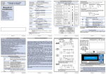
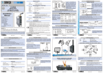
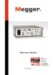
S203T
Analizzatore di Rete Trifase Avanzato
Descrizione Generale
L’S203T è un analizzatore di rete trifase completo, adatto a range di tensione fino a 600
Vac (50 Hz o 60 Hz), con correnti fino a 100 mA * Rapporto TA connesso .
Lo strumento è in grado di fornire tutte le seguenti grandezze elettriche: Vrms, Irms,
Watt, Var, Va, Frequenza, Cosf e Energia Attiva. Per le grandezze sopra elencate
(tranne la frequenza) sono disponibili sia i valori di fase che il valore complessivo trifase.
Tutti valori possono essere acquisiti tramite comunicazione seriale sia in formato floating
point sia normalizzate (eccetto frequenza e Energia Attiva).
E' anche possibile, tramite impostazione dei DIP-switch, la ritrasmissione analogica di una
qualsiasi delle grandezze Vrms, Irms, Watt e Cosf monofase, trifase o su una fase a scelta
(impostazione tramite registro MODBUS). In aggiunta il modulo è caratterizzato da:
Configurabilità della comunicazione tramite DIP-switch o via software.
Comunicazione seriale RS485 con protocollo MODBUS-RTU, massimo 32 nodi.
Alloggiato in contenitore DIN 43880 per rapido aggancio su guida DIN.
Elevata precisione: classe 0,2 %.
Protezione contro scariche ESD fino a 4 kV.
Isolamento ingresso di potenza: 3750 Vac rispetto a tutti gli altri circuiti.
Isolamento tra comunicazione e alimentazione: 1500 Vac.
Isolamento tra uscita analogica e alimentazione: 1500 Vac.
Uscita analogica impostabile in tensione o corrente.
Possibilità di collegamento e gestione di TA esterni.
Ammessi tutti i tipi di inserzione: monofase, Aron (trifase a due TA), quattro fili (trifase a
tre TA
Possibilità di compensare gli errori dovuti alle variazioni di frequenza in ambienti in cui
la frequenza di rete non sia stabile (fluttuazioni > 30 mHz).
Caratteristiche Tecniche
Alimentazione :
Consumo :
Porte di Comunicazione Seriale :
Protocollo :
Ingresso
Ingresso in Tensione :
Ingresso in Corrente :
10..40 Vdc o 19..28 Vac (50..60 Hz).
max 2,5 W.
RS485, 1200..115200 Baud.
MODBUS-RTU.
Resistenza massima del cavo
al secondario di ogni TA :
fino a 600 Vac, Frequenza: 50 o 60 Hz.
Portata nominale : (25 o 100) mArms * TA .
Max Fattore di cresta : 4.
Corrente Massima : (100 o 400) mApeak * TA.
Frequenza: 50 o 60 Hz.
Voltmetro : 0,2 %.
Amperometro : 0,2 %.
Wattmetro : 0,2 %.
3 W, pari alla somma del cavo di andata (da TA a
carico) e di ritorno (da carico a TA).
Uscita Ritrasmessa
Uscita in tensione :
0..10 Vdc, 0..5 Vdc, Min. resistenza di carico: 2 kW.
Classe/Prec. Base :
MI001264-I-E
Uscita in corrente :
Errore di ritrasmissione :
Tempo di risposta (10%..90%) :
Altre Caratteristiche
Tensione di isolamento :
Grado di protezione :
Condizioni ambientali :
Temp. Stoccaggio :
Segnalazioni LED :
Connessioni :
Contenitore :
Dimensioni (L x W x H) :
Normative :
Nei valori intermedi il comportamento è lineare. I valori delle ritrasmissioni saturano a
circa 11 V per le uscite in tensione e a circa 22 mA per le uscite in corrente (uscita
ritrasmessa limitata al 110 %).
Se la frequenza di rete si discosta di quantità superiori ai 30 mHz dai valori nominali (50 o
60 Hz), è possibile compensare gli errori sulle misure di Potenza ed Energia, causati da
queste fluttuazioni. Tale funzionalità è attivabile tramite registro MODBUS. Si evidenzia
che le misure di Vrms e Irms non sono influenzate dalle sopracitate oscillazioni di
frequenza.
All'accensione vengono prelevati i coefficienti di taratura appropriati (dipendenti dalla
scelta della frequenza 50 o 60 Hz). Tutte le impostazioni vengono caricate al reset.
Grandezze elettriche
Grandezza
Tensioni efficaci di fase (Vrms)
Tensione Media Trifase
Correnti efficaci di fase (Irms)
Corrente Media Trifase
Potenze Attive di fase
Potenza Attiva Totale Trifase
Potenze Reattive di fase
Potenza Reattiva Totale Trifase
Potenze Apparenti di fase
Potenza Apparente Totale Trifase
cosF di fase
cosF Totale Trifase
Frequenza
Energie Attive di fase
Energia Attiva Totale Trifase
3750 Vac tra ingresso di misura e i tutti gli altri circuiti.
1500 Vac tra alimentazione e comunicazione.
1500 Vac tra alimentazione e uscita ritrasmessa.
IP20.
Temperatura -10..+65 °C.
Umidità 30..90 % non condensante.
Altitudine 2000 slm.
-20..+85 °C.
Alimentazione, Fail, Comunicazione RS485.
Morsetti a vite, passo 5,08 mm.
Materiale plastico UL 94 VO, colore grigio.
105 x 89 x 60 mm
EN61000-6-4/2002-10 (emissione elettromagnetica,
ambiente industriale).
EN61000-6-2/2006-10 (immunità elettromagnetica,
ambiente industriale).
EN61010-1/2001 (sicurezza)
Tutti i circuiti devono essere isolati con doppio
isolamento dai circuiti sotto tensione pericolosa. Il
trasformatore di alimentazione deve essere a norma
EN60742: “Trasformatori di isolamento e
trasformatori di sicurezza”.
Valori
Valori
Misurati Calcolati
(IA+IB+IC)/3
2
(SA,B,C) -(PA,B,C)
QA+QB+QC
VA,B,C*IA,B,C
SA+SB+SC
PA,B,C/SA,B,C
P/S
33
32
31
GND
A
B
INGRESSO
MONOFASE
13 14 15 16 17 18
19 20 21 22
TA
VG
ZL
N
ARON
Trifase senza Neutro
13 14 15 16 17 18
MI001264-I-E
ITALIANO - 2/16
4 FILI
Trifase con Neutro
A
VG B
N C
35
28
29
19 20 21 22
Programmazione
Per i tool di programmazione e/o configurazione del prodotto consultare il sito
www.seneca.it. Durante la prima programmazione è possibile utilizzare le impostazioni di
default da EEPROM (SW3..8 in posizione OFF) che sono all'origine programmate come
segue: Indirizzo=001, VELOCITA'=38400 Baud, PARITA'=nessuna, NUMERO BIT=8,
STOP BIT=1.
30
ZL
TA
13 14 15 16 17 18 19 20 21 22
LED
36 35 34 33 32 31 30 29 28
ZL
TA
29: LED TX (ROSSO)
Acceso
Significato
Indica la trasmissione di dati sulla porta di comunicazione
RS485.
30: LED RX (ROSSO)
Acceso
Significato
Indica la ricezione di dati sulla porta di comunicazione RS485.
S SENECA
S203T
Interfaccia Seriale
Per informazioni dettagliate sull’interfaccia seriale RS485 fare riferimento alla
documentazione presente nel sito www.seneca.it, nella sezione Prodotti/Serie ZPC/MODBUS TUTORIAL.
Impostazione dei DIP-switch
Lo strumento esce dalla fabbrica configurato con tutti i DIP-switch in posizione 0. La
posizione dei DIP-switch definisce i parametri di comunicazione del modulo: indirizzo e
velocità e altre impostazioni che si descriveranno di seguito.
La Configurazione di default impostata dai Dip Switch è:
Baudrate : 38400.
Indirizzo: 1.
(1) Uscita attiva già alimentata da collegare a ingressi passivi.
(2) Uscita passiva non alimentata da collegare a ingressi attivi.
MI001264-I-E
10 11 12 13 14 15 16 17 18
SW1
SW2
ITALIANO - 5/16
MI001264-I-E
ITALIANO - 4/16
ITALIANO - 7/16
Frequenza di Rete: 50 Hz
Uscita : 0..10 V.
Tipo Applicazione : Trifase.
Tipo di Inserzione : 4 Fili.
Grandezza Ritrasmessa : Tensione Vrms media trifase.
Corrente Massima da misurare (con TA 1:1000) : 100 Arms.
In tutte le tabelle seguenti l’indicazione corrisponde a DIP-switch in 1 (ON);
nessuna indicazione corrisponde a DIP-switch in 0 (OFF)
VELOCITÀ
SW1 1 2
9600 Baud
19200 Baud
38400 Baud
57600 Baud
REGISTRI MODBUS
INDIRIZZO
SW1 3 4 5 6 7 8
I registri Holding Registers a 16 bit hanno la seguente struttura :
Parametri di comunicazione da EEPROM
Indirizzo fisso 01
Indirizzo fisso 02
Indirizzo fisso 03
Indirizzo fisso 04
X X X X X X Indirizzo fisso, come da rappresentazione binaria.
Indirizzo fisso 63
Lo strumento S203T dispone di registri MODBUS a 16 bit (word) accessibili tramite
comunicazione seriale RS485. Nei prossimi paragrafi si descrivono i comandi MODBUS
supportati e le funzionalità esprimibili dai vari registri.
Comandi MODBUS supportati
Codice
Funzione
03
Read Holding Registers
06
Write Single Register
16
Write Multiple Registers
Descrizione
Lettura di registri a word fino a 16 per volta.
Scrittura di un registro a word.
Scrittura di registri a word fino a 16 per volta.
Holding Registers
Bit più
significativo
Indice Bit
Bit meno
significativo
15 14 13 12 11 10 9 8 7 6 5 4 3 2 1 0
Word (16 bit): Registro MODBUS
USCITA ANALOGICA
SW2 2 3
0..10 V
0..5 V
0..20 mA
4..20 mA
La notazione Bit [x:y] riportata in tabella indica tutti i bit dal x a y. Ad esempio Bit [2:1] indica
il bit 2 e il bit 1, e serve ad illustrare il significato delle varie combinazioni congiunte di valori
dei due bit. Da ricordare che sui seguenti registri possono essere eseguite le funzioni
MODBUS 3, 6, 16 rispettivamente di lettura multipla e scrittura singola e multipla. I valori
di default sono contrassegnati con il simbolo *.
Questo documento è di proprietà SENECA srl. La duplicazione e la riproduzione sono vietate, se non autorizzate. Il
contenuto della presente documentazione corrisponde ai prodotti e alle tecnologie descritte. I dati riportati potranno
essere modificati o integrati per esigenze tecniche e/o commerciali. Il contenuto della presente documentazione
viene comunque sottoposto a revisione periodica.
SELEZIONE TIPO DI INSERZIONE TRIFASE: 4 FILI O ARON
SW2 5
4 Fili
Aron
R
THE INTERNATIONAL CERTIFICATION NETWORK
ISO9001-2000
MI001264-I-E
27 26 25 24 23 22 21 20 19
28: LED ERR (GIALLO) Significato
Acceso Fisso
Errore di comunicazione tra periferiche interne.
Tensione misurata inferiore a 40 Vac su almeno una delle
Lampeggio
fasi attive.
SELEZIONE TIPO DI APPLICAZIONE: MONOFASE O TRIFASE
SW2 4
Trifase
Monofase
TA
TA
Posizione Led, Morsetti e DIP-switch
27: LED PWR (VERDE) Significato
Indica la presenza dell’alimentazione.
Acceso
SELEZIONE FREQUENZA RETE (50 o 60 Hz)
SW2 1
Frequenza Rete 50 Hz
Frequenza Rete 60 Hz
TA
SCELTA GRANDEZZA RITRASMESSA
SW2 6 7
Ritrasmissione Vrms
Ritrasmissione Irms
Ritrasmissione Watt
Ritrasmissione cosf
CORRENTE MASSIMA DA MISURARE CON TA 1:1000
SW2 8
100 A
25 A
34
Non è presente isolamento tra RS485 e uscita ritrasmessa.
ITALIANO - 3/16
PORTA SERIALE RS485
C
A
V
34
EA+EB+EC
Non è presente isolamento tra RS485 e uscita analogica.
A
VG B
(2)
PWR ERR Tx Rx
2
Logica di funzionamento
Il modulo mette a disposizione, negli appositi registri MODBUS, i valori delle seguenti
grandezze elettriche: Vrms, Irms, Watt, Var, Va, Frequenza, Cosf e Energia Attiva. Nel
caso di applicazione trifase per ciascuna delle grandezze sopracitate oltre al valore trifase
(eccetto ovviamente la frequenza) sono disponibili i valori corrispondenti a ciascuna delle
tre fasi.
Tali valori sono disponibili sia in formato floating point sia normalizzate (eccetto la
Frequenza e l’Energia attiva) tra 0..+10000 (-10000 ..+10000 per VAR e Cosf). Il valore
dell’energia viene mantenuto in memoria e nel caso la macchina si spenga viene tenuto
l'ultimo valore prima dello spegnimento.
Tramite impostazione dei DIP-switch il modulo ritrasmette in uscita, come segnale in
corrente o tensione, una grandezze a scelta tra: Vrms, Irms, Watt, cosF. Se l’applicazione
è trifase lo strumento automaticamente trasmette il valore trifase della grandezza
selezionata, ma tramite registro Modbus l’utente può personalizzare la ritrasmissione
della grandezza su una delle tre fasi A, B e C.
L’utente può impostare tramite MODBUS i valori MIN e MAX della grandezza in ingresso
corrispondenti rispettivamente allo 0 % e al 100 % dell’uscita ritrasmessa. Ad esempio se
il segnale ritrasmesso è in corrente 4..20 mA e la grandezza da ritrasmettere la corrente
Irms nel range 10..3000 mA (quindi MIN=10, MAX=3000) avremo che se Irms=10 mA
allora l’uscita analogica varrà 4 mA mentre se Irms=3 A l’uscita ritrasmessa varrà 20 mA.
36
Significato Indicazioni
PA+PB+PC
10 ÷ 40 VDC
19 ÷ 28 VAC
2.5 W
A
Corrente Alim. Esterna
(VA+VB+VC)/3
MI001264-I-E
26
25
(1)
36
+
Posizione ed Identificazione Led
Range
Range Ritrasmissione Selezionabili
Grandezze
di misura
Elettriche
0..10 V, 0..5 V, 0..20 mA o 4..20 mA
Vrms
0..600 Vac
Irms
(0..25 o 0..100) mA * TA
0..10 V, 0..5 V, 0..20 mA o 4..20 mA
Potenza Attiva
(0..15 o 0..60) W * TA
0..10 V, 0..5 V, 0..20 mA o 4..20 mA
(0..15 o 0..60) VAR * TA
Potenza Reattiva
Potenza Apparente (0..15 o 0..60) VA * TA
cosf
0..1
5..10 V, 2,5..5 V, 10..20 mA o 12..20 mA
Frequenza
40..70 Hz
Energia Attiva
NOTA: Le precisioni riportate nella sezione Caratteristiche Tecniche sono garantite nei
seguenti range:
Vrms: 40..600 Vac
Irms: (0,1..25 o 0,4..100) mA * Rapporto TA
ALIMENTAZIONE
Corrente Impressa
Tensione
35
27
Q
SA SB SC
S
cosFA cosFB
cosFC
cosF_3PH
Hz
EA EB EC
E
Collegamenti Elettrici
Il modulo fornisce un’uscita in tensione (0..10 Vdc, 0..5 Vdc) o corrente attiva o passiva
(0..20 mA, 4..20 mA). Per i collegamenti elettrici si raccomanda l’utilizzo di cavi schermati.
Indicazioni tramite LED
Calcolo
Range di misura e ritrasmissione
ITALIANO - 1/16
0..20 mA, 4..20 mA, Max resistenza di carico: 500 W.
0,1 % (del campo massimo).
0,4 s.
Simboli
utilizzati
VA VB VC
V
IA IB IC
I
PA PB PC
P
QA QB QC
USCITA
+
I
MI001264-I-E
ITALIANO - 6/16
SENECA s.r.l.
Via Germania, 34 - 35127 - Z.I. CAMIN - PADOVA - ITALY
Tel. +39.049.8705355 - 8705359 - Fax +39.049.8706287
e-mail: [email protected] - www.seneca.it
MI001264-I-E
ITALIANO - 8/16
REGISTRO
MACHINE ID
CHECK_TA
Bit [15:1]
Bit 0
PHASE_RETR
Bit [15:0]
TA_RATIO_FL_MSW
Bit [15:0]
TA_RATIO_FL_LSW
MINOUT_FL_MSW
Bit [15:0]
Descrizione
IND. R/W
La parte alta del registro contiene l'ID del 40001 R
modulo (26).
La parte bassa la revisione esterna firmware.
Tipo di TA utilizzato: TA passivo (come quello
fornito in dotazione) o TA compensato.
Non utilizzati.
Imposta il tipo di TA che si utilizza :
0*: TA passivo (come quello fornito in dotazione).
1: TA compensato, avente errore di fase nullo.
La classe di precisione se il TA è passivo è
garantita solo con i TA forniti.
Seleziona la fase sulla quale avverrà la
ritrasmissione.
Imposta la fase sulla quale avverrà la
ritrasmissione della grandezza selezionata:
0: Fase A (default per applicazione monofase).
1: Fase B.
2: Fase C.
Tutti gli altri valori: Valore trifase (default per
applicazione trifase).
Impostazione il rapporto spire del TA (Formato
floating point, word più significativa).
Imposta il rapporto spire del TA collegato allo
strumento in formato floating point. Questo
rapporto influenza il valore floating point di: IRMS,
Potenza attiva, Potenza Apparente, Potenza
reattiva ed Energia (sia applicazione monofase
che trifase). Non influenza, invece, i valori interi (0
- 10000) e le ritrasmissioni. Default: 1000,0.
Impostazione coefficiente del TA (Formato
floating point, word meno significativa).
MAXOUT_FL_MSW
Bit [15:0]
MAXOUT_FL_LSW
CHECK_FREQ
Bit [15:1]
Bit 0
ADDR_PARITY
Bit [15:8]
Bit [7:0]
BAUDR_ANSDEL
Bit [15:8]
40025 R/W
40026 R/W
STATUS
Bit 15
Bit [14:7]
Bit 6
Bit 5
Bit 4
Bit 3
40027 R/W
Valore della grandezza da ritrasmettere cui 40028 R/W
corrisponde il valore minimo dell’uscita
ritrasmessa (formato floating point, word più
significativa).
Valore della grandezza da ritrasmettere (definita
tramite DIP-switch e con fase impostata mediante
registro PHASE_RETR, 40025) cui corrisponde il
valore minimo (0%) dell’uscita ritrasmessa. Il
valore è in formato floating point (word più
significativa) e quindi va espresso nell’unità di
misura relativa alla grandezza selezionata (V per
Vrms, mA per Irms, W per Watt) . Default: 0,0.
MI001264-I-E
MINOUT_FL_LSW
40024 R/W
comunicazione seriale (baudrate) :
00000000 (0x00) : 4800 Baud
00000001 (0x01) : 9600 Baud
00000010 (0x02) : 19200 Baud
00000011* (0x03) : 38400 Baud
00000100 (0x04) : 57600 Baud
00000101 (0x05) : 115200 Baud
00000110 (0x06) : 1200 Baud
00000111 (0x07) : 2400 Baud
Tempo di ritardo della risposta in caratteri.
Bit [7:0]
Rappresenta il numero di pause da 6 caratteri
ciascuna da inserire tra la fine del messaggio Rx e
l'inizio del messaggio Tx. Default: 0.
RESET_ZERO.ENER Reset strumento e azzeramento energia.
40131 R/W
-Scrivendo 0x1234, si comanda il reset (riavvio)
Bit [15:0]
del modulo.
-Scrivendo 0x1000, azzera il conteggio
dell’energia in tutte e tre le fasi.
Bit [2:0]
VRMS_A_FL_MSW
VRMS_A_FL_LSW
VRMS_B_FL_MSW
VRMS_B_FL_LSW
VRMS_C_FL_MSW
VRMS_C_FL_LSW
ITALIANO - 9/16
Registro di stato.
40133
1: Errore salvataggio valore Energia.
Non utilizzati.
1: Le fasi B e C sono invertite fra loro.
1: La tensione sulla fase C è > di 40 V e le misure
sulla fase C sono quindi correttamente acquisite.
1: La tensione sulla fase B è > di 40 V e le misure
sulla fase B sono quindi correttamente acquisite.
1: La tensione sulla fase A è > di 40 V e le misure
sulla fase A sono quindi correttamente acquisite.
Non utilizzati.
Misura Tensione Vrms monofase o fase A in 40135
Volt (floating point, word più significativa).
Misura Tensione Vrms monofase o fase A in 40136
Volt (floating point, word meno significativa).
Abilitazione compensazione errori di misura 40032 R/W
di Potenza ed Energia dovuti alle fluttuazioni
della frequenza di rete.
Non utilizzati.
Compensazione errori dovute alle fluttuazioni
della frequenza di rete:
1: Qualora la frequenza di rete non sia stabile a 50
Hz o 60 Hz o abbia fluttuazioni eccessive (> 30
mHz), corregge le misure della Potenza o
dell’Energia. Le misure di Vrms e Irms non sono
invece influenzate dallo stato di questo registro.
Registro per l'impostazione dell'indirizzo del 40033 R/W
modulo e del controllo di parità
Impostano l'indirizzo del modulo. Valori
ammissibili da 0x00 a 0xFF ( valori decimali
nell'intervallo 0-255 ). Default: 1.
Impostano il tipo di controllo sulla parità:
00000000* : nessuna parità ( NONE )
00000001 : parità pari
( EVEN )
00000010 : parità dispari ( ODD )
Registro per l'impostazione del baudrate e
40034 R/W
del tempo di ritardo della risposta in caratteri
Impostano il valore della velocità di
MI001264-I-E
ITALIANO - 10/16
R
R
R
R
R
R
Misura Corrente Irms fase B in mA (floating 40145
point, word più significativa).
Misura Corrente Irms fase B in mA (floating 40146
point, word meno significativa).
R
Misura Corrente Irms fase C in mA (floating 40147
point, word più significativa).
Misura Corrente Irms fase C in mA (floating 40148
point, word meno significativa).
R
IRMS_3PH_FL_MSW Corrente Irms media in mA: (IA+IB+IC)/3 40149
(floating point, word più significativa).
IRMS_3PH_FL_LSW Corrente Irms media in mA: (IA+IB+IC)/3 40150
(floating point, word meno significativa).
R
Misura Potenza Attiva monofase o fase A in W 40151
(floating point, word più significativa).
Misura Potenza Attiva monofase o fase A in W 40152
(floating point, word meno significativa).
R
Misura Potenza Attiva fase B in W (floating 40153
point, word più significativa).
Misura Potenza Attiva fase B in W (floating 40154
point, word meno significativa).
R
Misura Potenza Attiva fase C in W (floating 40155
point, word più significativa).
Misura Potenza Attiva fase C in W (floating 40156
point, word meno significativa).
R
WATT_3PH_FL_MSW Potenza Attiva totale trifase in W: PA+PB+PC 40157
(floating point, word più significativa).
WATT_3PH_FL_LSW Potenza Attiva totale trifase in W: PA+PB+PC 40158
(floating point, word meno significativa).
R
Potenza Reattiva monofase o fase A in VAR 40159
(floating point, word più significativa).
Potenza Reattiva monofase o fase A in VAR 40160
(floating point, word meno significativa).
R
WATT_A_FL_MSW
WATT_A_FL_LSW
WATT_B_FL_MSW
WATT_B_FL_LSW
WATT_C_FL_MSW
WATT_C_FL_LSW
VAR_A_FL_MSW
VAR_A_FL_LSW
MI001264-I-E
Potenza Reattiva fase B in VAR
point, word meno significativa).
(floating 40162
R
WATT_A_INT
Potenza Attiva monofase o fase A in scala 40201
0..+10000.
R
VAR_C_FL_MSW
Potenza Reattiva fase C in VAR
point, word più significativa).
Potenza Reattiva fase C in VAR
point, word meno significativa).
(floating 40163
R
WATT_B_INT
Potenza Attiva fase B in scala 0..+10000.
40202
R
(floating 40164
R
WATT_C_INT
Potenza Attiva fase C in scala 0..+10000.
40203
R
Potenza Reattiva trifase in VAR: QA+QB+QC 40165
(floating point, word più significativa).
Potenza Reattiva trifase in VAR: QA+QB+QC 40166
(floating point, word meno significativa).
R
WATT_3PH_INT
Potenza Attiva totale trifase PA+PB+PC in scala 40204
0..+10000.
R
VAR_A_INT
R
R
Potenza Reattiva monofase o fase A in scala:
-10000..+10000.
40205
Potenza Apparente monofase o fase A in VA 40167
(floating point, word più significativa).
Potenza Apparente monofase o fase A in VA 40168
(floating point, word meno significativa).
VAR_B_INT
Potenza Reattiva fase B in scala:
-10000..+10000.
40206
R
Potenza Apparente fase B in VA (floating point, 40169
word più significativa).
Potenza Apparente fase B in VA (floating point, 40170
word meno significativa).
R
VAR_C_INT
Potenza Reattiva fase C in scala:
-10000..+10000.
40207
R
R
VAR_3PH_INT
Potenza Reattiva totale trifase QA+QB+QC in 40208
scala: -10000..+10000.
R
Potenza Apparente fase C in VA (floating point, 40171
word più significativa).
Potenza Apparente fase C in VA (floating point, 40172
word meno significativa).
R
VA_A_INT
Potenza Apparente fase A in scala 0..+10000.
40209
R
R
VA_B_INT
Potenza Apparente fase B in scala 0..+10000.
40210
R
Trifase in VA:SA+SB+SC 40173
più significativa).
Trifase in VA:SA+SB+SC 40174
meno significativa).
R
VA_C_INT
Potenza Apparente fase C in scala 0..+10000.
40211
R
R
VA_3PH_INT
Potenza Apparente totale trifase SA+SB+SC in 40212
scala 0..+10000.
R
Fattore di potenza cosF monofase o fase A 40175
(floating point, word più significativa).
Fattore di potenza cosF monofase o fase A 40176
(floating point, word meno significativa).
R
cosF_A_INT
Fattore di potenza cosF monofase o fase A in 40213
scala: -10000..+10000.
R
cosF_B_INT
R
R
Fattore di potenza cosF fase B in scala:
-10000..+10000.
40214
Fattore di potenza cosF fase B (floating point, 40177
word più significativa).
Fattore di potenza cosF fase B (floating point, 40178
word meno significativa).
cosF_C_INT
Fattore di potenza cosF fase C in scala:
-10000..+10000.
40215
R
Fattore di potenza cosF fase C (floating point, 40179
word più significativa).
R
cosF_3PH_INT
Fattore di potenza cosF trifase WATT/VA in 40216
scala: -10000..+10000
R
VAR_C_FL_LSW
VAR_3PH_FL_MSW
VAR_3PH_FL_LSW
VA_A_FL_MSW
VA_A_FL_LSW
VA_B_FL_MSW
VA_3PH_FL_LSW
cosF_A_FL_MSW
cosF_B_FL_MSW
cosF_B_FL_LSW
R
IRMS_C_FL_LSW
R
VAR_B_FL_LSW
cosF_A_FL_LSW
Misura Corrente Irms monofase o fase A in mA 40143
(floating point, word più significativa).
Misura Corrente Irms monofase o fase A in mA 40144
(floating point, word meno significativa).
IRMS_C_FL_MSW
Corrente Irms media (IA+IB+IC)/3 in scala 40200
0..+10000.
cosF_C_FL_MSW
ITALIANO - 11/16
IRMS_A_FL_MSW
IRMS_B_FL_LSW
IRMS_3PH_INT
VA_3PH_FL_MSW
R
Valore della grandezza da ritrasmettere cui 40030 R/W
corrisponde il valore massimo dell’uscita
ritrasmessa (formato floating point, word più
significativa).
Valore della grandezza da ritrasmettere (definita
tramite DIP-switch e con fase impostata mediante
registro PHASE_RETR, 40025) cui corrisponde il
valore massimo (100%) dell’uscita ritrasmessa. Il
valore è in formato floating point (word più
significativa) e quindi va espresso nell’unità di
misura relativa alla grandezza selezionata (V per
Vrms, mA per Irms, W per Watt). Default: 600,0.
IRMS_B_FL_MSW
R
VA_C_FL_LSW
Misura Tensione Vrms fase C in Volt (floating 40139
point, word più significativa).
Misura Tensione Vrms fase C in Volt (floating 40140
point, word meno significativa).
VRMS_3PH_FL_MSW Tensione Vrms media in Volt: (VA+VB+VC)/3 40141
(floating point, word più significativa).
VRMS_3PH_FL_LSW Tensione Vrms media in Volt: (VA+VB+VC)/3 40142
(floating point, word meno significativa).
IRMS_A_FL_LSW
(floating 40161
VA_C_FL_MSW
R
MI001264-I-E
Potenza Reattiva fase B in VAR
point, word più significativa).
VA_B_FL_LSW
Misura Tensione Vrms fase B in Volt (floating 40137
point, word più significativa).
Misura Tensione Vrms fase B in Volt (floating 40138
point, word meno significativa).
Valore della grandezza da ritrasmettere cui 40029 R/W
corrisponde il valore minimo dell’uscita
ritrasmessa (formato floating point, word
meno significativa).
Valore della grandezza da ritrasmettere cui 40031 R/W
corrisponde il valore massimo dell’uscita
ritrasmessa (formato floating point, word
meno significativa).
R
VAR_B_FL_MSW
R
R
R
R
R
R
R
MI001264-I-E
ITALIANO - 12/16
R
R
R
ITALIANO - 13/16
cosF_C_FL_LSW
Fattore di potenza cosF fase C (floating point, 40180
word meno significativa).
R
cosF_3PH_FL_MSW
cosF trifase: WATT_3PH / VA_3PH (floating 40181
point, word più significativa).
cosF trifase: WATT_3PH / VA_3PH (floating 40182
point, word meno significativa).
R
Misura della frequenza in Hz (floating point, 40183
word più significativa).
Misura della frequenza in Hz (floating point, 40184
word meno significativa).
R
Misura energia attiva monofase o fase A in Wh 40185
(floating point, word più significativa).
Misura energia attiva monofase o fase A in Wh 40186
(floating point, word meno significativa).
R
Misura energia attiva fase B in Wh (floating 40187
point, word più significativa).
Misura energia attiva fase B in Wh (floating 40188
point, word meno significativa).
R
Misura energia attiva fase C in Wh (floating 40189
point, word più significativa).
Misura energia attiva fase C in Wh (floating 40190
point, word meno significativa).
R
ENER_3PH_FL_MSW Energia attiva trifase in Wh: EA+EB+EC (floating 40191
point, word più significativa).
ENER_3PH_FL_LSW Energia attiva trifase in Wh: EA+EB+EC (floating 40192
point, word meno significativa).
R
VRMS_A_INT
Tensione Vrms monofase o fase A in scala 40193
0..+10000.
R
VRMS_B_INT
Tensione Vrms fase B in scala 0..+10000.
40194
R
VRMS_C_INT
Tensione Vrms fase C in scala 0..+10000.
40195
R
VRMS_3PH_INT
Tensione Vrms media (VA+VB+VC)/3 in scala 40196
0..+10000.
R
IRMS_A_INT
Corrente Irms monofase o fase A in scala 40197
0..+10000.
R
IRMS_B_INT
Corrente Irms fase B in scala 0..+10000.
40198
R
cosF_3PH_FL_LSW
FREQ_FL_MSW
FREQ_FL_LSW
ENER_A_FL_MSW
ENER_A_FL_LSW
ENER_B_FL_MSW
ENER_B_FL_LSW
ENER_C_FL_MSW
ENER_C_FL_LSW
R
R
Potenza Apparente
(floating point, word
Potenza Apparente
(floating point, word
R
MI001264-I-E
RETRANS_INT
Visualizza la grandezza da ritrasmettere con 40217
scala 0..+10000, riportata ai limiti min e max
impostati.
Bit [15:0]
Valore della grandezza da ritrasmettere in scala
0..+10000, riportato ai limiti minimo e massimo
impostati rispettivamente nei registri
MINOUT_FL (40028-29) e MAXOUT_FL (4003031).
Vale 0: se il valore float della grandezza da
ritrasmettere è < di MINOUT_FL (40028-29).
Vale 10000: se il valore float della grandezza da
ritrasmettere è pari a MAXOUT_FL( 40030-31).
Nei valori intermedi il comportamento è lineare.
Il valore del registro segue poi linearmente il
valore della grandezza da ritrasmettere fino al
limite massimo raggiungibile pari a 11000,
saturando a tale valore.
R
R
R
R
Smaltimento dei rifiuti elettrici ed elettronici (applicabile
nell’Unione Europea e negli altri paesi con servizio di raccolta
differenziata).
Il simbolo presente sul prodotto o sulla sua confezione indica che il prodotto non verrà
trattato come rifiuto domestico. Sarà invece consegnato al centro di raccolta
autorizzato per il riciclo dei rifiuti elettrici ed elettronici. Assicurandovi che il prodotto
venga smaltito in modo adeguato, eviterete un potenziale impatto negativo
sull’ambiente e la salute umana, che potrebbe essere causato da una gestione non
conforme dello smaltimento del prodotto. Il riciclaggio dei materiali contribuirà alla
conservazione delle risorse naturali. Per ricevere ulteriori informazioni più dettagliate
Vi invitiamo a contattare l’ufficio preposto nella Vostra città, il servizio per lo
smaltimento dei rifiuti o il fornitore da cui avete acquistato il prodotto.
R
Questo documento è di proprietà SENECA srl. La duplicazione e la riproduzione sono vietate, se non autorizzate. Il
contenuto della presente documentazione corrisponde ai prodotti e alle tecnologie descritte. I dati riportati potranno
essere modificati o integrati per esigenze tecniche e/o commerciali. Il contenuto della presente documentazione
viene comunque sottoposto a revisione periodica.
R
Corrente Irms fase C in scala 0..+10000.
MI001264-I-E
40199
R
R
THE INTERNATIONAL CERTIFICATION NETWORK
IRMS_C_INT
ITALIANO - 15/16
R
ITALIANO - 14/16
ISO9001-2000
SENECA s.r.l.
Via Germania, 34 - 35127 - Z.I. CAMIN - PADOVA - ITALY
Tel. +39.049.8705355 - 8705359 - Fax +39.049.8706287
e-mail: [email protected] - www.seneca.it
MI001264-I-E
ITALIANO - 16/16
S203T Advanced Three-phase Network Analyzer
General Description
Model S203T is a complete three-phase network analyzer suited for use with up to
600Vac voltage range, and up to 100mA+(TA ratio) current range.
The instrument provides all the following electrical measurable quantities: Vrms, Irms,
Watt, Var, Va, Frequency, Cosf and Active Energy. All measurements given above
(except frequency) are available both single-phase and three-phase.
Measurements are read through serial communication both in floating point and
normalised format (except Frequency and Active Energy).
The DIP-switches can be set for the analog retransmission of any Vrms, Irms, Watt and
Cosf quantity either single phase or three-phase, or any phase chosen (by specific
MODBUS registry). The module is also distinguished by:
? Communication configurability through DIP-switch or software.
? RS485 serial communication with MODBUS-RTU protocol, maximum 32 nodes.
? Easy-wiring of power supply and serial bus by means of the bus housed in the DIN rail.
? High precision: 0,2 % class.
? Protection against ESD discharge up to 4 kV.
? Power input insulation: 3750 Vac towards all the other circuits.
? Insulation between communication and power supply: 1500Vac.
? Insulation between retransmitted output and power supply: 1500Vac.
? Analog output signal settable in voltage or current.
? Possibility for connection and management by external CTs.
? All kind of insertion possible: single phase, Aron (three-phase with 2 CTs), four wires
(three-phase with 3 CTs).
? Possibility to compensate errors caused by frequency change in places where network
frequency is not stable (frequency changes > 30 mHz).
Technical Specifications
Power Supply :
Consumption :
Communication Ports:
Protocol :
Input
Voltage Input
Current Input :
(1)
Class/Base Accuracy :
Max Resistance of each CT’s
secondary wire :
Analog Output
Voltage Output :
10..40 Vdc o 19..28 Vac (50..60 Hz).
max 2,5 W.
RS485, 1200..115200 Baud.
MODBUS-RTU.
Up to 600 Vac, Frequency: 50 o 60 Hz.
Rated range :given by INOMINAL of CT.
Max Crest Factor : 4.
Maximum Current : 4*INOMINAL of CT.
Network Frequency: 50 or 60 Hz.
Voltmeter : 0,2 %.
Amperometer : 0,2 %.
Wattmeter : 0,2 %.
The sum of the resistance of the wire going (from CT to
load) and back (from load to CT) < 3W
0..10 Vdc, 0..5 Vdc, Min. load resistance: 2 kW.
Mi001264-I-E
Current Output :
Transmission error :
Response time (10%..90%) :
Other Specifications
Insulation voltage :
International protection :
Environmental conditions :
Storage temperature :
Signalling by LED :
Connections :
Box :
Dimensions (L x W x H) :
Reference standards :
In the intermediate points the behaviour is linear. The retransmission values saturate at
approximately 11 V for voltage output and at 22mA for current output (analog output
clamped at 110 %).
If network frequency oscillates more than 30 mHz from rated values (50 o 60 Hz), it’s
possibile to compensate errors on measurements of Power and Energy caused by these
variations. This option is selectable via MODBUS register. Vrms and Irms measurements
are not influenced by these variations.
When the module is switched on, the appropriate setting coefficients are measured
(depending on the choice of 50 or 60 Hz frequency). All the settings made will be
automatically loaded when the module is reset.
Symbols Measured Calculated
Equation
Values
Values
used
used
VA V B V C
(VA+VB+VC)/3
V
IA IB IC
(IA+IB+IC)/3
I
PA PB PC
PA+PB+PC
P
QA QB QC
(SA,B,C)2-(PA,B,C)2
Total three phase reactive power
QA+QB+QC
Q
Apparent power (phase)
VA,B,C*IA,B,C
SA S B S C
Total three phase apparent power
SA+SB+SC
S
cosfA cosfB
PA,B,C/SA,B,C
cosf (phase)
cosfC
Total three-phase cosf
cosf_3PH
P/S
Frequency
Hz
Active Energy (phase)
EA EB EC
Total three-phase active energy
EA+EB+EC
E
Electrical
Quantity
Root-mean squared voltage
Mean three phase voltage
Root-mean squared current
Mean three phase current
Active power (phase)
Total three phase active power
Reactive power (phase)
Measurement and retransmission range
Electrical
Measurement
Selectable retransmission
Quantity
Range
Range
Vrms
0..600 Vac
0..10 V, 0..5 V, 0..20 mA o 4..20 mA
Irms
(0..25 or 0..100)mA * TA
0..10 V, 0..5 V, 0..20 mA o 4..20 mA
Active Power
(0..15 or 0..60)W * TA
0..10 V, 0..5 V, 0..20 mA o 4..20 mA
Reactive Power (0..15 or 0..60)VAR * TA
(0..15 or 0..60)VA * TA
Apparent Power
Cosf
0..1
5..10 V, 2,5..5 V, 10..20 mA o 12..20 mA
40..70 Hz
Frequency
Active Energy
NOTE: (1) Accuracy reported in Technical Specifications is given in the following range:
Vrms: 40..600 Vac
Irms: (0,1..25 or 0,4..100)mA* TA ratio
3750 Vac between the measurement input and all the
other circuits.
1500 Vac between power supply and communication.
1500 Vac between power supply and analog output.
IP20.
Temperature -10..+65 °C.
Humidity 30..90 % non-condensing.
Altitude 2000 slm.
-20..+85 °C.
Power supply, Fail, RS485 communication.
Removable 3-way screw terminals, 5.08 mm pitch.
Plastic UL 94 VO, grey color.
105 x 89 x 60 mm
EN61000-6-4/2002-10 (electromagnetic emission,
industrial environment).
EN61000-6-2/2006-10 (electromagnetic immunity,
industrial environment).
EN61010-1/2001 (safety)
All circuits must be insulated from the other circuits
under dangerous voltage with double insulation. The
power supply transformer must comply with EN60742:
“Insulated transformers and safety transformers”.
33
32
31
10 ÷ 40 VDC
19 ÷ 28 VAC
2.5 W
GND
A
13 14 15 16 17 18
CT
ZL
13 14 15 16 17 18
Mi001264-I-E
ENGLISH - 2/16
N C
Programming
Indications by LED on the frontal panel
For the product’s programming and/or configuration tools, consult the website
www.seneca.it.
During initial programming, the EEPROM (SW1 3..8 in OFF position) default setting
values originally programmed as follows can be used:
Address=001, SPEED=38400 Baud, PARITY=none, BIT NUMBER=8, STOP BIT=1.
Position and Identification of LEDs
27
28
29
30
Leds position, Screw terminals and DIP-switch
PWR ERR Tx Rx
LED
Led Indications
27: PWR LED (GREEN) Description
36 35 34 33 32 31 30 29 28
Steady On
Power supply is present
28: ERR LED (YLW)
Description
Steady On
Communication error between internal peripherals
Blinking
At least one of the active phases’ voltage is less than 40 Vac
29: TX LED (RED)
Description
Steady On
Data are being transmitted through the RS485 comm. port
30: RX LED (RED)
Description
Steady On
Data are being received through the RS485 comm. port
19 20 21 22
CT
ZL
CT
13 14 15 16 17 18 19 20 21 22
CT
CT
ZL
CT
Mi001264-I-E
ENGLISH - 4/16
27 26 25 24 23 22 21 20 19
S SENECA
S203T
Serial interface
For detailed information on RS485 serial interface, consult the documentation provided by
the website www.seneca.it, in the section Prodotti/Serie Z-PC/MODBUS TUTORIAL.
DIP-SWITCH SETTING
The instrument leaves the factory with all DIP-switches configured in position 0. The
setting of the DIP-switches defines the module’s communication parameters: address and
speed and the following settings
The Default Configuration is the following:
Baudrate : 38400.
Address : 1.
10 11 12 13 14 15 16 17 18
Mi001264-I-E
SW1
SW2
ENGLISH - 5/16
Mi001264-I-E
ENGLISH - 7/16
MODBUS REGISTERS
S203T has MODBUS 16 bits (words) registers, accessible by RS485 communication. In
the next paragraphs, we shall describe the supported MODBUS commands, and the
functions of the registers.
Supported MODBUS Commands
Function
03
Read Holding Registers
06
Write Single Register
16
Write Multiple Register
Description
Reading of registers up to 16 words at a time
within the same group
Writing of a word register
Writing of registers up to 16 words at a time
within the same group
Holding Registers
The 16-bit Holding Registers have the following structure:
ADDRESS
SW1 3 4 5 6 7 8
NETWORK FREQUENCY SELECTION (50 o 60 Hz)
SW2 1
Network frequency 50 Hz
Network frequency 60 Hz
C
A
34
Communication Parameters from EEPROM
Fixed Address: 01
Fixed Address: 02
Fixed Address: 03
Fixed Address: 04
X X X X X X Fixed Address, as from binary representation
Fixed Address: 63
N
VG B
35
MAXIMUM CURRENT TO MEASURE WITH 1:1000 CT
SW2 8
100 A
25 A
Code
19 20 21 22
VG
4 WIRES
(Three-Phase with
Neutral)
34
In all the following tables, the indication corresponds to a DIP-switch set in 1(ON); no
indication is provided when the DIP-switch is set in 0 (OFF).
SPEED
SW1 1 2
9600 Baud
19200 Baud
38400 Baud
57600 Baud
SINGLE
PHASE
A
VG B
36
A
V
B
There is no insulation between RS485 and the analog output
Operating logic
The module measures the following electrical quantities: Vrms, Irms, Watt, Var, Va,
Frequenza, Cosf and Active Energy, and provides the values in the corresponding
MODBUS registers.
In three-phase environments, measurements given above corresponding to any phase
are available, other than the three-phase value (except the frequency of course).
These measurements are rendered in both floating point and normalised format (except
Frequency and Active energy) between 0..+10000 (-10000 ..+10000 for VAR e Cosf).
Active energy value is stored in memory and when the instrument is switched off, the last
value before switching is kept in memory.
The module output can transmit, via DIP-switch setting, one of the following quantities:
Vrms, Irms, Watt, cosF as either a current or voltage value. If the instrument is set for threephase measurements, it transmits automatically the three-phase value of the selected
measurement. However, via MODBUS register, the user can choose to transmit any phase
(A, B, C) corresponding measurement .
The user can set through MODBUS the values MIN and MAX of the measurement to
transmit corresponding to 0% and 100% of the analog output. For example, if the signal is
transmitted as current 4..20 mA and the quantity to transmit is voltage Vrms in the 10..300.
V range, (therefore MIN=10, MAX=300), then if Vrms measured is 10V, analog output will
be 4mA, while if Vrms=300V output will be 20mA.
Ext. Power Supply Current(2)
Network Frequency : 50 Hz.
Analog Output : 0..10 V.
Environment : Three-phase.
Insertion type : 4 wires.
Transmitted quantity : Mean three-phase voltage.
Maximum current to measure (with 1:1000 CT) : 100 Arms.
SERIAL PORT RS485
POWER SUPPLY
ARON
(Three-Phase
without Neutral)
(1)
36
+
ENGLISH - 3/16
Electric connections
A
Active Current
Voltage
35
SELECTION OF QUANTITY RETRANSMITTED
SW2 6 7
Retransmission of Vrms
Retransmission of Irms
Retransmission of Watt
Retransmission of cosf
(1) Passive Output already powered to connect to passive inputs.
(2) Passive Output not powered to connect to active inputs.
Mi001264-I-E
26
25
The module provides an analog output in voltage (0..10 Vdc, 0..5 Vdc) or active and
passive current (0..20 mA, 4..20 mA). We recommend using shielded cables for the
electric connections.
There is no insulation between RS485 and the analog output.
Electrical Measurements
ENGLISH - 1/16
0..20 mA, 4..20 mA, Max load resistance: 500 W.
0,1 % (max range).
0,4 s.
OUTPUT
+
EN
Most significant
Bit
Index Bit
Least
Significant Bit
15 14 13 12 11 10 9 8 7 6 5 4 3 2 1 0
Word (16 bit): MODBUS Register
ANALOG OUTPUT
SW2 2 3
0..10 V
0..5 V
0..20 mA
4..20 mA
The Bit notation [x:y] shown in the table indicates all the bits from x to y. For example, Bit
[2:1] indicates bit 2 and bit 1, and illustrates the meaning of the various linked
combinations of the values of the two bits. Remember that the MODBUS 3, 6 and 16
functions (respectively of multiple reading, single and multiple writing) can be executed on
the following registers. Default values are marked with * symbol.
The following indication (only readable or also writable) is probided for every register:
R: Readable
W: Writeable
SELECTION OF ENVIRONMENT: SINGLE-PHASE OR THREE-PHASE
SW2 4
Three-phase
Single-phase
This document is property of SENECA srl. Duplication and reprodution are forbidden, if not
authorized. Contents of the present documentation refers to products and technologies described
in it. All technical data contained in the document may be modified without prior notice Content of
SELECTION OF INSERTION TYPE: 4-WIRES OR ARON
SW2 5
4 Wires
Aron
Mi001264-I-E
R
THE INTERNATIONAL CERTIFICATION NETWORK
ISO9001-2000
ENGLISH - 6/16
SENECA s.r.l.
Via Germania, 34 - 35127 - Z.I. CAMIN - PADOVA - ITALY
Tel. +39.049.8705355 - 8705359 - Fax +39.049.8706287
e-mail: [email protected] - www.seneca.it
Mi001264-I-E
ENGLISH - 8/16
REGISTER
MACHINE ID
CHECK_TA
Bit [15:1]
Bit 0
PHASE_RETR
Bit [15:0]
TA_RATIO_FL_MSW
Bit [15:0]
TA_RATIO_FL_LSW
MINOUT_FL_MSW
Bit [15:0]
Description
IND. R/W
Bit [15:8] contain the module’s ID: 26.
40001 R
Bit [7:0] contain the firmware’s external
revision
Kind of CT used: passive CT or compensated
CT
Not used.
Select the kind of CT used:
0*: Passive CT (like the CT in bundle).
1: Compensated CT, which has no phase error.
Precision class if CT is passive is granted only
with bundle CTs.
Select the phase on which the analog output
will transmit.
Select the phase on which the analog output
wil transmit the quantity selected:
0: Phase A (default for single-phase ).
1: Phase B.
2: Phase C.
All other values: Three phase value (default threephase).
Select the rated current of CTs in floating point
(most significative word ).
Select the rated current of the CTs connected to
the instrument in floating point format. This
register influences floating point value of: Irms,
Active power, Apparent Power, Reactive Power
and Energy (both single and three-phase). It
doesn’t influence normalised values (0 - 10000)
and transmitted output. Default: 1000,0.
Select the rated current of CTs in floating point
(least significative word ).
MAXOUT_FL_MSW
Bit [15:0]
MAXOUT_FL_LSW
CHECK_FREQ
Bit [15:1]
Bit 0
ADDR_PARITY
Bit [15:8]
Bit [7:0]
BAUDR_ANSDEL
Bit [15:8]
Bit [7:0]
40025 R/W
40026 R/W
STATUS
Bit 15
Bit [14:7]
Bit 6
Bit 5
Bit 4
Bit 3
40027 R/W
Bit [2:0]
VRMS_A_FL_MSW
VRMS_A_FL_LSW
VRMS_B_FL_MSW
VRMS_B_FL_LSW
VRMS_C_FL_MSW
VRMS_C_FL_LSW
ENGLISH - 9/16
Value of the quantity to transmit which gives 40029 R/W
the minimum retransmitted output (floating
point format, least significative word).
Value of the quantity to transmit which gives 40030 R/W
the maximum retransmitted output (floating
point format, most significative word).
Value of the quantity to transmit (defined via DIPswitch and phase selected via PHASE_RETR
register,40025) which gives the maximum value
(100%) of the transmitted output. The value is
expressed in floating point format (most
significative word) and therefore it must be
expressed in the corresponding measurement
unit of the quantity chosen (V for Vrms, mA for
Irms, W for Watt) . Default: 600,0.
Value of the quantity to transmit which gives 40031 R/W
the maximum retransmitted output (floating
point format, least significative word).
Enables measurement errors compensation 40032 R/W
of Active Power and Energy caused by
network frequency variations.
Not used
Errors compensation caused by network
frequency variations:
1: If network frequency is not stable at 50 Hz or 60
Hz, or has consistent variations (> 30 mHz), this
register corrects the measurement of Power and
Energy. The measurements of Vrms and Irms are
not influenced by this setting.
Register for the setting of the module’s
40033 R/W
address and parity control.
Set the module’s address. Allowed values from
0x00 a 0xFF (decimal values in the interval of 0255 ). Default: 1.
Set the type of parity control:
00000000* : No parity
( NONE )
00000001 : Even parity
( EVEN )
00000010 : Odd parity
( ODD )
Register for the setting of the Baud rate and 40034 R/W
the response delay time in characters.
Set the serial communication speed value
(Baudrate):
Mi001264-I-E
RESET_ZERO
ENERGY
Bit [15:0]
Value of the quantity to transmit which gives 40028 R/W
the minimum retransmitted output (floating
point format, most significative word).
Value of the quantity to transmit (defined via DIPswitch and phase selected via PHASE_RETR
register, 40025 ) which gives the minimum value
(0%) of the transmitted output. The value is
expressed in floating point format (most
significative word) and therefore it must be
expressed in the corresponding measurement
unit of the quantity chosen (V for Vrms, mA for
Irms, W for Watt) . Default: 0,0.
Mi001264-I-E
MINOUT_FL_LSW
40024 R/W
ENGLISH - 10/16
00000000 (0x00) : 4800 Baud
00000001 (0x01) : 9600 Baud
00000010 (0x02) : 19200 Baud
00000011* (0x03) : 38400 Baud
00000100 (0x04) : 57600 Baud
00000101 (0x05) : 115200 Baud
00000110 (0x06) : 1200 Baud
00000111 (0x07) : 2400 Baud
Set the response delay time in characters that
represents the number of pauses of 6 characters
each to be entered between the end of the Rx
message and the start of the Tx message.
Default: 0
Reset instrument and zero setting energy
40131 R/W
Status Register
40133
1: Error saving Active Energy value.
Not Used.
1: Phase B and C are reverse-connected
1: Voltage on phase C is > 40 V therefore
measurements on phase C are correctly acquired.
1: Voltage on phase B is > 40 V therefore
measurements on phase B are correctly acquired.
1: Voltage on phase A is > 40 V therefore
measurements on phase A are correctly acquired.
Non utilizzati.
Single phase or phase A Vrms measurement 40135
(floating point, most significative word) in Volt
Single phase or phase A Vrms measurement 40136
(floating point, least significative word) in Volt
R
Phase B Vrms measurement (floating point, 40137
most significative word) in Volt
Phase B Vrms measurement (floating point, 40138
least significative word) in Volt
R
Phase C Vrms measurement (floating point, 40139
most significative word) in Volt
Phase C Vrms measurement (floating point, 40140
least significative word) in Volt
R
R
R
R
R
IRMS_3PH_FL_MSW Mean Irms in mA: (IA+IB+IC)/3 (floating point, 40149
most significative word).
IRMS_3PH_FL_LSW Mean Irms in mA: (IA+IB+IC)/3 (floating point, 40150
least significative word).
R
Single phase or phase A Power measurement 40151
(floating point, most significative word) in W
Single phase or phase A Power measurement 40152
(floating point, least significative word) in W
R
Phase B Power measurement (floating point, 40153
most significative word) in W
Phase B Power measurement (floating point, 40154
least significative word) in W
R
Phase C Power measurement (floating point, 40155
most significative word) in W
Phase C Power measurement (floating point, 40156
least significative word) in W
R
WATT_3PH_FL_MSW Three phase Power in W: PA+PB+PC (floating 40157
point, most significative word).
WATT_3PH_FL_LSW Three phase Power in W: PA+PB+PC (floating 40158
point, least significative word).
R
Single phase or phase A Reactive Power in 40159
VAR (floating point, most significative word).
Single phase or phase A Reactive Power in 40160
VAR (floating point, least significative word).
R
WATT_B_FL_MSW
WATT_B_FL_LSW
WATT_C_FL_MSW
WATT_C_FL_LSW
VAR_A_FL_MSW
VAR_A_FL_LSW
Mi001264-I-E
cosF_B_FL_MSW
cosF_C_FL_MSW
ENGLISH - 11/16
R
WATT_A_FL_LSW
cosF_A_FL_MSW
cosF_B_FL_LSW
Phase C Irms measurement (floating point, 40147
most significative word) in mA.
Phase C Irms measurement (floating point, 40148
least significative word) in mA.
WATT_A_FL_MSW
VA_3PH_FL_LSW
cosF_A_FL_LSW
R
IRMS_C_FL_LSW
VA_B_FL_MSW
VA_3PH_FL_MSW
Phase B Irms measurement (floating point, 40145
most significative word) in mA.
Phase B Irms measurement (floating point, 40146
least significative word) in mA.
IRMS_C_FL_MSW
VAR_3PH_FL_LSW
VA_C_FL_LSW
R
IRMS_B_FL_LSW
VAR_3PH_FL_MSW
VA_C_FL_MSW
Single phase or phase A Irms measurement 40143
(floating point, most significative word) in mA
Single phase or phase A Irms measurement 40144
(floating point, least significative word) in mA
IRMS_B_FL_MSW
VAR_C_FL_LSW
VA_B_FL_LSW
R
IRMS_A_FL_LSW
VAR_C_FL_MSW
VA_A_FL_LSW
VRMS_3PH_FL_MSW Mean Vrms in Volt: (VA+VB+VC)/3 (floating 40141
point, most significative word).
VRMS_3PH_FL_LSW Mean Vrms in Volt: (VA+VB+VC)/3 (floating 40142
point, least significative word).
IRMS_A_FL_MSW
VAR_B_FL_LSW
VA_A_FL_MSW
-Writing 0x1234 resets(boots) instrument.
-Writing 0x1000, resets active energy
accumulation in all three phases.
Mi001264-I-E
VAR_B_FL_MSW
R
R
R
R
R
R
R
R
ENGLISH - 12/16
R
Phase C Reactive Power in VAR (floating point, 40163
most significative word).
Phase C Reactive Power in VAR (floating point, 40164
least significative word).
R
Reactive power three-phase in VAR: QA+QB+QC 40165
(floating point, most significant word).
Reactive power three-phase in VAR: QA+QB+QC 40166
(floating point, least significant word).
R
Single phase or phase A Apparent Power in VA 40167
(floating point, most significative word).
Single phase or phase A Apparent Power in VA 40168
(floating point, least significative word).
R
Phase B Apparent Power in VA (floating point, 40169
most significative word).
Phase B Apparent Power in VA (floating point, 40170
least significative word).
R
Phase C Apparent Power in VA (floating point, 40171
most significative word).
Phase C Apparent Power in VA (floating point, 40172
least significative word).
R
Apparent Power Three-phase in VA: SA+SB+SC 40173
(floating point, most significative word).
Apparent Power Three-phase in VA: SA+SB+SC 40174
(floating point, least significative word).
R
Single phase or phase A Power factor 40175
(floating point, most significative word).
Single phase or phase A Power factor 40176
(floating point, least significative word).
R
Phase B Power factor cosF (floating point, 40177
most significative word).
Phase B Power factor cosF (floating point, 40178
least significative word).
R
Phase C Power factor cosF (floating point, 40179
most significative word).
R
Mi001264-I-E
R
R
R
IRMS_3PH_INT
40200
R
WATT_A_INT
Single phase or phase A Active power 40201
normalised 0..+10000.
R
WATT_B_INT
Phase B Active power normalised 0..+10000.
40202
R
WATT_C_INT
Phase C Active power normalised 0..+10000.
40203
R
WATT_3PH_INT
Three phase active power P A +P B +P C 40204
normalised 0..+10000.
R
VAR_A_INT
Single phase or phase A Reactive Power 40205
normalised -10000..+10000.
R
VAR_B_INT
Phase B Reactive Power normalised - 40206
10000..+10000.
R
VAR_C_INT
Phase C Reactive Power normalised - 40207
10000..+10000.
R
VAR_3PH_INT
Three phase reactive power QA +QB +QC 40208
normalised -10000..+10000.
R
VA_A_INT
Single phase or phase A Apparent Power 40209
normalised 0..+10000
R
VA_B_INT
Phase B Apparent Power normalised 40210
0..+10000
R
VA_C_INT
Phase C Apparent Power normalised 40211
0..+10000
R
VA_3PH_INT
Apparent power three phase S A +S B +S C 40212
normalised 0..+10000.
R
cosF_A_INT
Single phase or phase A power factor cosF 40213
normalised: -10000..+10000.
R
cosF_B_INT
Phase B power factor cosF normalised: 40214
-10000..+10000.
R
cosF_C_INT
Phase C power factor cosF normalised: 40215
-10000..+10000.
R
cosF_3PH_INT
Three phase power factor cosF=WATT/VA 40216
normalised: -10000..+10000
R
R
R
R
R
R
ENGLISH - 13/16
Mi001264-I-E
Phase C Power factor cosF (floating point, 40180
least significative word).
R
RETRANS_INT
cosF_3PH_FL_MSW
cosF three phase: WATT_3PH / VA_3PH 40181
(floating point, most significative word).
cosF three phase: WATT_3PH / VA_3PH 40182
(floating point, least significative word).
R
Bit [15:0]
Frequency measurement in Hz (floating point, 40183
most significative word).
Frequency measurement in Hz (floating point, 40184
least significative word).
R
Single phase or phase A Active Energy in Wh 40185
(floating point, most significative word).
Single phase or phase A Active Energy in Wh 40186
(floating point, least significative word).
R
Phase B Active Energy in Wh (floating point, 40187
most significative word).
Phase B Active Energy in Wh (floating point, 40188
least significative word).
R
Phase C Active Energy in Wh (floating point, 40189
most significative word).
Phase C Active Energy in Wh (floating point, 40190
least significative word).
R
ENER_3PH_FL_MSW Active energy three phase in Wh: EA+EB+EC 40191
(floating point, most significative word).
ENER_3PH_FL_LSW Active energy three phase in Wh: EA+EB+EC 40192
(floating point, least significative word).
R
VRMS_A_INT
Single phase or phase A Vrms normalised 40193
0..+10000.
R
VRMS_B_INT
Phase B Vrms normalised 0..+10000.
40194
R
VRMS_C_INT
Phase C Vrms normalised 0..+10000.
40195
R
VRMS_3PH_INT
Mean Vrms
0..+10000.
(V A +V B +V C )/3 normalised 40196
R
IRMS_A_INT
Single phase or phase A Irms normalised 40197
0..+10000.
R
IRMS_B_INT
Phase B Irms normalised 0..+10000.
40198
R
IRMS_C_INT
Phase C Irms normalised 0..+10000.
40199
R
cosF_3PH_FL_LSW
FREQ_FL_MSW
FREQ_FL_LSW
ENER_A_FL_MSW
ENER_A_FL_LSW
ENER_B_FL_MSW
ENER_B_FL_LSW
ENER_C_FL_MSW
ENER_C_FL_LSW
Mean Irms (IA+IB+IC)/3 normalised 0..+10000.
R
cosF_C_FL_LSW
R
R
Phase B Reactive Power in VAR (floating point, 40161
most significative word).
Phase B Reactive Power in VAR (floating point, 40162
least significative word).
Visualize the quantity to transmit normalised 40217
0..+10000, scaled to min and MAX values set.
Value of the quantity to transmit normalised
0..+10000, scaled to the minimum and maximum
threshlod set in registers MINOUT_FL (4002829) e MAXOUT_FL (40030-31) respectively.
0: if the floating point value of the quantity to
transmit is less than MINOUT_FL (40028-29).
10000: if the floating point value of the quantity to
transmit is equal to MAXOUT_FL (40030-31).
In the intermediate points has a linear behaviour.
The value of the register follows linearly the
quantity to transmit until maximum value set to
11000, saturating over this value.
R
R
R
R
R
R
Disposal of Electrical & Electronic Equipment (Applicable throughout
the European Union and other European countries with separate
collection programs)
This symbol, found on your product or on its packaging, indicates that
this product should not be treated as household waste when you wish
to dispose of it. Instead, it should be handed over to an applicable
collection point for the recycling of electrical and electronic equipment.
By ensuring this product is disposed of correctly, you will help prevent
potential negative consequences to the environment and human
health, which could otherwise be caused by inappropriate disposal of
this product. The recycling of materials will help to conserve natural
resources. For more detailed information about the recycling of this
product, please contact your local city office, waste disposal service or
thè retail store where you purchased this product.
R
This document is property of SENECA srl. Duplication and reprodution are forbidden, if not
authorized. Contents of the present documentation refers to products and technologies described
in it. All technical data contained in the document may be modified without prior notice Content of
this documentation is subject to periodical revision.
R
THE INTERNATIONAL CERTIFICATION NETWORK
Mi001264-I-E
ENGLISH - 15/16
ENGLISH - 14/16
ISO9001-2000
SENECA s.r.l.
Via Germania, 34 - 35127 - Z.I. CAMIN - PADOVA - ITALY
Tel. +39.049.8705355 - 8705359 - Fax +39.049.8706287
e-mail: [email protected] - www.seneca.it
Mi001264-I-E
ENGLISH - 16/16