1
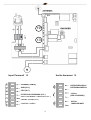
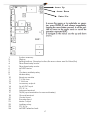
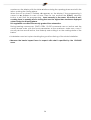
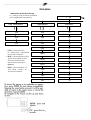
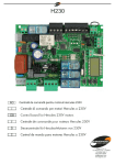
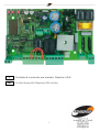
I
GB
Centrale di comando per barriere Daphne a 24V
Control board for Daphne 24V motors
1
I
D24 di Stagnoli è la centrale di comando studiata per le barriere Daphne a 24V.
Realizzata solo con materiali di prima scelta, è stata progettata per avere bassi
assorbimenti a riposo permettendo un basso consumo di energia elettrica. Particolare
attenzione è stata rivolta ai professionisti del settore facilitando la programmazione della
centrale grazie a un display multilingua (4lingue).
AVVERTENZE E NORME DI SICUREZZA
•
Il presente manuale è stato realizzato da Stagnoli per lo specifico utilizzo da parte
di personale professionista e qualificato .
•
Si consiglia di leggere interamente il manuale di istruzioni prima di procedere
all’installazione del prodotto.
•
Durante la cablatura non deve esserci la presenza di tensione sull’impianto.
•
Gli impianti di cancelli automatici devono essere installati da personale tecnico
qualificato e nel rispetto delle norme di legge.
•
DOPPIA SICUREZZA: La centrale è dotata di due sensori di sicurezza: uno ad
encoder e l’altro amperometrico.
•
Verificare che la barriera sia solida, ben fissata con fissaggi adatti all’automazione
Daphne.
Informare accuratamente l’utilizzatore finale sulla modalità d’uso, sulla
pericolosità residua, sulla necessità della manutenzione e sulla necessità di un
controllo dei dispositivi di sicurezza, almeno ogni sei mesi.
2
Freccia Su
Freccia giù
Enter / Esc
1.
2.
3.
4.
5.
6.
7.
8.
9.
10.
11.
12.
13.
14.
15.
16.
17.
18.
19.
20.
21.
22.
23.
24.
Memoria impianto
Display
Tasti di impostazione(3a freccia su,3b freccia giù e 3c Enter / Esc)
Relè direzione motore
Relè direzione motore
MOSFET motore
//
Relè ausiliario di cortesia
Relè lampeggiante
Modulo ricevitore
Fusibile T 3.15A
Fusibile T 10A
Uscite accessori
Ingresso 24 AC/DC
PTC 0.1 A
Morsetto antenna
TX/RX ( sincronizzazione per seconda barriera )
Morsetto di terra
Input comandi
Input Encoder
Uscita motore
Relè ausiliario
PTC 0.9 A
MOSFET serratura
3
19
13
Input Comandi 19
Uscite Accessori 13
COMUNE (+24Vdc)
ELETTROSERRATURA/
ELETTROMAGNETICA
APRI (N.O.)
STOP (N.C)
FOTOCELLULA CHIUSURA (N.C.)
+24Vac
(PER ACCESSORI)
FOTO. APERTURA / CHIUSURA (N.C )
CHIUDI / START (N.O )
USCITA
LAMPEGGIANTE
COMUNE (+24Vdc)
4
La linea di alimentazione 230V verso l’automatismo deve essere protetta da un interruttore
magnetotermico oppure da una coppia di fusibili da 1A.
Un interruttore differenziale è consigliato ma non indispensabile se già presente a monte
dell’impianto.
Alimentare l’automatismo attraverso un cavo da 3x1,5mm2 (fase+neutro+terra). Se la
distanza fra la centrale e la connessione all’impianto di terra supera i 30m è necessario
prevedere un dispersore di terra in prossimità della centrale.
I cablaggi devono essere effettuati ad alimentazione 230V scollegata.
Gli ingressi dei contatti di tipo N.C. (normalmente chiuso), se non utilizzati, vanno
ponticellati con un morsetto comune (+24VDC). Se per lo stesso ingresso ci sono più
contatti N.C., questi vanno posti in serie tra di loro.
Gli ingressi dei contatti di tipo N.O. (normalmente aperto), se non usati, vanno lasciati
liberi. Se per lo stesso ingresso ci sono più contatti N.O., questi vanno posti in parallelo tra
di loro.
Procedura operativa al primo avvio
• Effettuare i cablaggi elettrici richiesti dall’impianto
e controllarli a scheda spenta.
• Sbloccare la barriera e controllarne il movimento.
La corsa della barriera non deve presentare punti
duri durante il movimento che deve essere fluido.
Tensionare la molla di contrasto fino a quando
l’asta della barriera sbloccata non raggiunge
l’apertura di 45°.
• Bloccare la barriera a metà della sua corsa e
alimentare la centrale.
A questo punto si accenderà il led di presenza rete e sul display della centrale
comparirà la scritta r-00 (r indica che il ricevitore integrato è in modalità rolling code e
00 indica che non ci sono trasmettitori memorizzati) .
• Entrare nel menù premendo il tasto E (Enter) . Con la freccia giù scorrere nel menu fino
alla voce lingua. Premere nuovamente il tasto E(Enter). Selezionare la lingua desiderata
scorrendo il sottomenu con i tasti freccia. Premere il tasto E(Enter) per confermare la
lingua desiderata, successivamente tenere premuto il tasto E(ESC)per uscire dal menù
lingua.
• Attivare uno alla volta i dispositivi di sicurezza e verificare che a display compaia la
scritta di diagnostica relativa. Ad esempio, far intervenire la fotocellula e verificare che
compaia a display il messaggio pho se si tratta di fotocellula attiva solo in chiusura o
phoA se si tratta di fotocellula attiva sia in chiusura che in apertura.
• Con la freccia giù scorrere il menu fino alla voce apprendimento e premere
nuovamente il tasto E (Enter). A questo punto la barriera andrà in apertura (se dovesse
andare in chiusura invertire i cavi del motore; se non dovesse muoversi ne in apertura
ne in chiusura, verificare che le sicurezze e l’encoder siano correttamente collegati),
poi andrà in chiusura e ripeterà l’operazione una volta. Le prime due manovre servono
5
per identificare l’inizio e la fine della corsa del motore, le due seguenti servono a
rilevare il picco di assorbimento del motore durante l’apertura e la chiusura della
barriera. In questa fase è necessario monitorare i valori visualizzati a display. Questi
valori, importanti per la sicurezza amperometrica, sono indicati dalle due cifre del
display precedute dalla lettera a durante la fase di apertura, dalla lettera c durante la
fase di chiusura.
Al termine della fase di apprendimento, sul display sarà visualizzato ok nel caso di
corretta programmazione o err nel caso vi siano stati degli errori. Per uscire dalla
programmazione premere per due secondi il tasto di selezione E(Esc). Impostare
correttamente i livelli di forza antischiacciamento in apertura e in chiusura nel menu,
che devono essere superiori ai valori massimi visualizzati durante l’apprendimento.
Questa regolazione può influire sul grado di sicurezza dell’automazione.
Durante le manovre di apprendimento, la centrale ignora i comandi di START, OPEN,
CLOSE e lavora con i parametri di forza al massimo. Anche se rimangono attive le
sicurezze, assicurarsi che non vi siano oggetti o persone sulla traiettoria di lavoro della
barriera.
• Effettuare alcuni cicli di prova verificando il corretto funzionamento di tutto l’impianto.
• Effettuare le misure della forza di impatto della barriera secondo quanto specificato
dalle norme EN12445
6
MENU’ AD ALBERO
Indicazioni al primo avvio
• r = indicatore ricevitore rolling code
• 00 = trasmettitori memorizzati
r - 00
Agg. radiocomandi
regolazioni
1ch
ttca
ca
2ch
rlap
ba
3ch
rlch
bp
rpm
cr
rpmc
2p
fm1a
pl
Fm1c
sv
sbat
re
ch r
en
relè
ss
• 1Ch = memorizzazione
del comando
start/close
sul primo canale
• 2Ch = memorizzazione
del comando open
sul secondo canale nel
funzionamento
open/close (OC=1)
• 3Ch = memorizzazione
del comando relè
sul terzo canale
funzioni
oc
cf
3c
sc
ms
7
sl
00
cancella
lingua
reset parametri
italiano
Cancella 1 radiocomando
francese
Cancella tutta la memoria
radio
inglese
apprendimento
leggi codice
spagnolo
Funzioni
Regolazioni
•
•
•
•
•
•
•
•
•
•
•
•
•
•
•
•
•
•
•
•
•
•
ttca = tempo di chiusura automatica
rlap = corsa rallentata in apertura
rlch = corsa rallentata in chiusura
rpm = velocità motore
rpmc= regolazione velocità e intensità del
rallentamento durante la chiusura.
fm1a = forza antischiacciamento del
motore in apertura
fm1c = forza antischiacciamento del
motore in chiusura
sbat = spazio di battuta
ch r = chiusura rapida
relé = tempo relé ausiliario
•
•
•
•
Cancella
ca = chiusura automatica
ba = blocca impulsi durante l’apertura
bp= blocca impulsi durante la pausa
cr = chiusura rapida
2p = funzionamento apri / chiudi
Pl = prelampeggio
sv = serratura a ventosa
re = risparmio energetico
en = funzionamento encoder
ss = soft start
oc = funzionamento open /close
cf = funzionamento del ricevitore integrato
a codice fisso
3c = terzo canale radiocomando
sc = spia barriera aperta
ms = master
Sl = slave
Apprendimento = apprendimento della corsa
• Reset parametri = ripristino dei parametri di
fabbrica
• Cancella 1 radiocomando = cancellazione di
un trasmettitore
• Cancella tutta la memoria radio = cancellazione
di tutti i trasmettitori memorizzati
Leggi codice = identificazione e riconoscimento
trasmettitori
8
Configurazione della centrale
Per la configurazione della centrale di comando, ogni parametro è accessibile dal menu
ad albero visualizzato tramite display.
Per accedere ai menù o per eseguire un’operazione, premere il tasto E (ENTER)
rilasciandolo velocemente. Prolungando la pressione sullo stesso tasto, sarà possibile
tornare al menù superiore o annullare l’operazione richiesta (ESC).
Per navigare nei menu o nei sottomenu, usare i tasti freccia.
ATTENZIONE: Durante la navigazione nei menu, la centrale ignora i comandi di
START/CLOSE e di OPEN.
In stand-by il display mostra la scritta r – 00 dove r indica radiocomandi rolling code e le
due cifre seguenti indicano quanti radiocomandi sono presenti in memoria. La lettera f
indica radiocomandi codice fisso. Esempio: f – 03 in questo caso la scritta indica la
presenza in memoria di 3 radiocomandi a codice fisso.
Quando il display mostra questa scritta, attraverso i tasti freccia su e giù possiamo
commutare la sua visualizzazione in modalità controllo amperometrico. In questa
modalità il display mostra tre cifre indicanti la corrente assorbita durante il movimento
della barriera e due lettere indicanti lo stato della barriera: op = aperto; cl = chiuso; ba =
in battuta di apertura; bc = in battuta di chiusura. Esempio 00ch indica barriera chiusa e
assorbimento di corrente nullo.
Questi parametri sono utili per tarare i parametri di sicurezza amperometrica e di spazio di
battuta.
Con display in stand-by è possibile accedere al menu principale premendo il testo E.
Navigando con i tasti freccia è possibile scorrere le varie voci di configurazione.
In successione troviamo: aggiunta radiocomandi regolazioni funzioni cancella lingua apprendimento leggi codici.
9
Aggiunta radiocomandi
Prima di memorizzare un trasmettitore, assicurarsi che sia compatibile con la tipologia di
ricevitore integrato (con display a riposo apparirà r, se si tratta di un ricevitore in modalità
rolling code o f se si tratta di un ricevitore in modalità codice fisso). Il ricevitore può
memorizzare codici rolling code di tipo HCS300 STAGNOLI con miliardi di combinazioni o
codici fissi di tipo HT53200 a 13 bit o la parte fissa di un codice rolling code (28 bit SN). É
possibile memorizzare fino a 76 codici (trasmettitori diversi).
• Entrare nel sottomenu aggiunta radiocomando premendo il tasto E(ENTER), scegliere il
canale che si vuole memorizzare portandosi sulla scritta a display 1ch o 2ch o 3ch
tramite i tasti freccia. Premere il tasto E(ENTER) per confermare il canale da
memorizzare. Successivamente premere il tasto del radiocomando che si desidera
memorizzare quando viene visualizzata la scritta premi: a questo punto il display
visualizzerà la scritta ok se l’operazione viene portata a termine in maniera corretta, err
nel caso si verifichino errori di registrazione o full se la memoria del ricevitore è piena.
Se non accadrà nulla significa che il telecomando utilizzato non rientra nello standard
adottato da Stagnoli.
• Installando un’antenna esternamente alla centrale e lontana dal suolo, l’area di
visibilità tra trasmettitori e centrale aumenta. Ricordarsi, inoltre, che parti metalliche e
cemento armato, se posti tra la centrale e il ricevitore, diminuiscono la capacità di
ricezione di questo ultimo.
Regolazioni
Le regolazioni dei parametri si effettuano entrando nel sottomenu regolazioni. Scegliere il
parametro da modificare tramite i tasti freccia e premere E(ENTER) per visualizzare il valore
impostato. Utilizzare i tasti freccia per modificare il parametro e confermare tramite il
tasto E(ENTER).
Per uscire dai menù tenete premuto il tasto E(ESC) per circa 2 secondi.
• ttca (tempo di chiusura automatica): è il tempo che intercorre tra l’apertura completa
della barriera e la sua chiusura che avviene in modo automatico. Se la fotocellula è
occupata, il tempo di ttca viene conteggiato dal momento in cui la fotocellula si
disimpegna. Il tempo impostato di default è 10sec ed è regolabile da 1 a 240sec.
• rlap (corsa rallentata in apertura): la centrale rallenta la corsa del motore nella parte
finale della sua fase di apertura. Il rallentamento impostato di default è il 50% della
corsa ed è regolabile da 0 a 90. Impostare questo valore affinché la barriera non
presenti forti oscillazioni nell’arrivare a fine corsa in apertura.
• rlch (corsa rallentata in chiusura): la centrale rallenta la corsa del motore nella parte
finale della sua fase di chiusura. Il rallentamento impostato di default è il 50% della
corsa ed è regolabile da 0 a 90. Impostare questo valore affinché la barriera non
presenti forti oscillazioni nell’arrivare a fine corsa in chiusura.
• rpm (velocità motore): impostare la velocità del motore durante la sua fase di
apertura/chiusura. La velocità impostata di default è 5 ed è regolabile da 1 a 10.
10
• rpmc (velocità di rallentamento durante la chiusura ): impostare la velocità del motore
durante la fase di rallentamento in chiusura. La velocità impostata di default è 18 ed
è regolabile da 5 a 20.
Stagnoli consiglia di impostare questo parametro nelle barriere da 3 o 4 metri da 15-18
e da 6mt da 18-20.
• fm1a (forza antischiacciamento del motore in apertura): è la forza antischiacciamento
della barriera. La forza impostata di default è 50 e può essere regolata da 10 a 99.
• fm1c (forza antischiacciamento del motore in chiusura): è la forza antischiacciamento
della barriera. La forza impostata di default è 50 e può essere regolata da 10 a 99.
ATTENZIONE: l’impostazione di questi due parametri può influire sul grado di sicurezza
dell’impianto stesso. Si consiglia di impostare questi parametri con un margine di
sicurezza tale che risultino almeno +10 rispetto al massimo della corrente consumata dal
motore rispettivamente in fase di apertura e di chiusura. La corrente assorbita durante la
corsa del motore si può leggere sul display nella seconda schermata principale (controllo
amperometrico).
fm1a e fm1c bassi di valore, indicano una maggiore sensibilità antischiacciamento. Valori
troppo bassi potrebbero rilevare come ostacolo un punto duro di movimentazione e
quindi di assorbimento di corrente più elevato.
Verificare al termine dell’installazione che le forze di impatto rispettino la norma
EN12453.
• sbat (spazio di battuta): è la percentuale della corsa individuata come spazio di
battuta. In questa zona la sicurezza encoder o amperometrica verrà rilevata come fine
corsa e non come ostacolo. Il valore impostato di default è 10 e può essere regolato
da 5 a 20.
• ch r (tempo di chiusura rapida): è il tempo di chiusura automatica nel caso in cui vi sia
un passaggio attraverso le fotocellule durante la fase di apertura o a barriera aperta, il
tempo della regolazione ttca (se attivato e maggiore di ch r) viene automaticamente
ridotto al tempo ch r impostato. Il valore di default è 3 e può essere impostato da 1 a
10 sec.
• relè (tempo relé ausiliario): è il tempo durante il quale il contatto del relé ausiliario
rimane chiuso dopo che la barriera si è chiusa. In caso di parametro 3c attivo questo
valore indica quanti secondi rimarrà chiuso il contatto relé ausiliario dopo che si è
premuto il terzo canale del radiocomando.
Funzioni
Le regolazioni dei parametri si effettuano entrando nel sottomenu funzioni. Scegliere il
parametro da modificare tramite i tasti freccia e premere E(ENTER) per visualizzare se la
funzione è attivata (1) o se disattivata (0).Per modificare lo stato premere i tasti freccia.
Successivamente confermare tramite il tasto E(ENTER) e uscire tenendo premuto il tasto
E(ESC) per circa 2 secondi.
• ca (chiusura automatica): chiusura automatica della barriera dopo la sua completa
apertura. Impostare la regolazione ttca per personalizzare il tempo che deve
intercorrere tra la fine dell’apertura e l’inizio della chiusura automatica.
11
• ba (blocco impulsi durante l’apertura): la centrale ignora gli impulsi di START durante la
fase di apertura.
• bp (blocco impulsi durante la pausa): la centrale ignora gli impulsi di START/CLOSE,
OPEN durante la pausa tra l’apertura e la chiusura automatica. Queste funzioni si
rivelano utili nei casi in cui vi siano diversi passaggi con diversi
input attraverso lo stesso ingresso.
• cr (chiusura rapida): attiva il tempo di chiusura rapida automatica dopo il passaggio
attraverso le fotocellule durante la fase di apertura o a barriera aperta. Il tempo della
regolazione ttca (se attivato e superiore di ch r) viene automaticamente ridotto al
tempo ch r impostato.
• 2p (funzionamento apri/chiudi): se attivo, ad ogni impulso di START, il movimento della
barriera inverte la direzione (APERTURA - CHIUSURA). Se disattivo la sequenza di
movimento della barriera diventa APERTURA - FERMATA (ttca) - CHIUSURA - STOP.
• pl (prelampeggio): dopo il comando di apertura della barriera, il lampeggiante o la
luce di cortesia si attivano per due secondi prima che venga iniziata la fase di apertura
o di chiusura.
• sv (serratura elettromagnetica): se attiva l’uscita elettroserratura diventa sempre attiva
(+24VDC) a barriera chiusa.
• re (risparmio energetico): mantiene le fotocellule spente mentre l’impianto non è attivo
consentendo risparmi energetici. Le fotocellule, così, rimangono attive solo durante il
movimento della barriera. Collegare l’alimentazione +/-24V sia del trasmettitore che
del ricevitore delle fotocellule all’uscita predisposta per il lampeggiante.
• en (funzionamento encoder): gestisce il funzionamento del motore con encoder. In
caso di guasto dell’encoder (la barriera si blocca poco dopo la sua partenza e sul
display viene visualizzata la scritta enc1), è possibile disattivare questa funzione e
permettere al motore di effettuare ulteriori manovre a uomo presente, cioè
mantenendo in pressione il tasto START/CLOSE o OPEN.
ATTENZIONE: il funzionamento del sistema senza l’encoder è da considerarsi una
gestione di emergenza. In questa modalità ogni ostacolo incontrato dal motore
comanda l’arresto del movimento senza la sua inversione.
• ss (soft start): permette al motore di effettuare una partenza dolce e a velocità ridotta
per diminuire la sollecitazione delle parti meccaniche dell’impianto. Attivando questa
funzione, il motore eroga una forza minore nella sua fase di partenza.
• oc (funzionamento open/close): l’ingresso in morsettiera di START diventa CLOSE. In
questa modalità un comando apre la barriera e l’altro lo chiude.
• cf (funzionamento della ricevente integrata a codice fisso): se attivo la ricevente
funziona con i codici fissi.
• 3c (terzo canale radiocomando): se attivo, alla pressione del terzo canale del
radiocomando, il contatto del relé ausiliario si chiude per il tempo impostato nel
parametro relé. (ricordarsi di aver memorizzato il terzo canale radio).
12
• sc (spia barriera aperta): se attivo l’uscita elettroserratura/ventosa diventa l’uscita spia
barriera aperta. Finché la barriera rimane aperta questa uscita rimarrà attiva a +24VDC.
• ms (master): attivare questa funzione se si desidera che la centrale diventi master in una
configurazione a due barriere (vedere paragrafo sincronizzazione). In questo modo la
centrale riceve i comandi di apertura chiusura e fotocellule secondo il cablaggio
effettuato e trasmette alla centrale slave i comandi per controllare il movimento
sincronizzato. ATTENZIONE: non attivare entrambe i parametri ms e sl.
• sl (slave): attivare questa funzione se si desidera che la centrale diventi slave in una
configurazione a due barriere (vedere paragrafo sincronizzazione). In questo modo i
comandi di apertura chiusura e fotocellule sono ricevuti dalla centrale master che
controlla i movimenti. ATTENZIONE: non attivare entrambe i parametri ms e sl.
Cancella
In questo sottomenu è possibile ripristinare i parametri di fabbrica o cancellare i
radiocomandi presenti in memoria. Entrando nel sottomenu cancella scegliere la voce
desiderata tramite i tasti freccia e confermare con il tasto E(ENTER). Uscire tenendo
premuto il tasto E(ESC) per circa 2 secondi.
• reset parametri: per reimpostare tutti i valori delle regolazioni e delle funzioni a quelli di
fabbrica premere il tasto E(ENTER) e portarsi sulla dicitura reset parametri del sottomenu
e premere il tasto E(ENTER). Verrà visualizzato il messaggio rese che lampeggerà fino a
quando non sarà confermata l’intenzione di reimpostare tutti i parametri tramite tasto
E(ENTER) o di annullare l’operazione tramite tasto E(ESC).
• cancella 1 radiocomando: per cancellare il codice di un trasmettitore, portarsi sulla
dicitura 1 radiocomando del sottomenu e premere il tasto E(ENTER). Verrà visualizzato il
messaggio premi. Premere a questo punto il tasto del trasmettitore da cancellare. Se
l’operazione sarà portata a termine in maniera corretta, verrà visualizzato il messaggio
ok. In caso contrario, err.
• cancella tutta memoria radio: per cancellare tutti i trasmettitori registrati, portarsi sulla
dicitura tutta memoria radio del sottomenu e premere il tasto E(ENTER). Verrà
visualizzato il messaggio prg che lampeggerà fino a quando non sarà confermata
l’intenzione di cancellare tutti i codici registrati premendo il tasto E(ENTER) o di annullare
l’operazione premendo il tasto E(ESC).
N.B: Per portare a termine la cancellazione della memoria radio viene richiesto di
confermare due volte la volontà di effettuare la cancellazione stessa (cancella tutta
memoria radio e prg).
Lingua
Il display può visualizzare i messaggi in più lingue: italiano, francese, inglese e spagnolo.
Per scegliere la lingua di funzionamento premere il tasto E(ENTER) e portarsi sul sottomenu
lingua attraverso i tasti freccia e premere E(ENTER) per entrare nel menù .Portarsi sulla
lingua desiderata tramite i tasti freccia e confermare premendo nuovamente E(ENTER).
Per uscire dal menù lingua premere per due secondi il tasto E(ESC).
13
Apprendimento
Questa operazione permette all’automazione di stabilire automaticamente l’inizio e la
fine della corsa. Prima di procedere con questa operazione, assicurarsi che la barriera sia
solidamente installata e che la funzione en della centrale sia attiva (Stagnoli fornisce la
centrale con questa funzione già attivata en=1).
Posizionare la barriera a metà corsa. Premere il tasto E(ENTER) per entrare nel menù e
spostarsi con i tasti freccia fino ad arrivare al sottomenu apprendimento e premere il
tasto E(ENTER). A questo punto la barriera andrà in apertura (se dovesse andare in
chiusura invertire i cavi del motore; se non dovesse muoversi ne in apertura ne in
chiusura, verificare che le sicurezze e l’encoder siano correttamente collegate), poi
andrà in chiusura e ripeterà l’operazione un’altra volta. Le prime due manovre servono
per identificare l’inizio e la fine della corsa del motore. Le due seguenti, servono a rilevare
il picco di assorbimento del motore durante l’apertura e la chiusura della barriera. In
questa fase, monitorare i valori visualizzati a display. Questi valori, importanti per la
sicurezza amperometrica, sono indicati dalle due cifre del display precedute dalla lettera
a durante la fase di apertura, dalla lettera c durante la fase di chiusura.
Al termine della fase di apprendimento, sul display sarà visualizzato ok nel caso di corretta
programmazione, o err nel caso vi siano stati degli errori. Per uscire dalla programmazione
premere il tasto di selezione E(ENTER). Impostare correttamente i livelli di forza
antischiacciamento in apertura e in chiusura nel menu, che devono essere superiori ai
valori massimi visualizzati durante l’apprendimento
ATTENZIONE: questa regolazione può influire sul grado di sicurezza dell’automazione.
Durante le manovre di apprendimento, la centrale ignora i comandi di START, OPEN,
CLOSE e lavora con i parametri di forza al massimo. Anche se rimangono attive le
sicurezze, assicurarsi che non vi siano oggetti o persone sulla traiettoria di lavoro della
barriera.
Effettuare alcuni cicli di prova verificando il corretto funzionamento di tutto l’impianto.
Effettuare le misure della forza di impatto della barriera secondo quanto specificato dalle
norme EN12445.
Leggi codice
È possibile verificare se un radiocomando è già stato memorizzato oppure leggere il
codice di un nuovo telecomando verificando così la compatibilità con la centrale. Per
effettuare tale operazione entrare nel sottomenu leggi codice tramite il tasto E(ENTER).
Quando sul display verrà visualizzato il messaggio premi, premere il tasto del trasmettitore
che si desidera verificare.
• prima schermata: Sr01 oppure Sf01oppure –r01 oppure –f01 ecc..
Il primo carattere indica il produttore del radiocomando, dove S indica Stagnoli mentre un produttore generico.
Il secondo carattere indica la tipologia di codice, dove r indica rolling code mentre f
indica codice fisso.
Gli ultimi due caratteri indicano il canale del tasto premuto.
• seconda schermata: P_00, dove P indica la parola “posizione” mentre la cifra
successiva (progressiva da 0 a 75) indica la posizione occupata dal trasmettitore in
memoria. Se il trasmettitore non dovesse essere presente in memoria, apparirà sul display ---.
14
• terza e quarta schermata: verrà visualizzata la codifica esadecimale del trasmettitore.
N.B Durante la comparsa della scritta premi , se alla pressione del tasto del
radiocomando non cambia nulla, significa che il radiocomando utilizzato non è
compatibile con la centrale Stagnoli (assicurarsi prima che il modulo ricevente sia inserito
bene nello zoccolo e che sia montata correttamente l’antenna).
Sincronizzazione
Tramite due centrali Daphne è possibile configurare due barrire in modo sincronizzato
permettendo di raddoppiare la larghezza dell’apertura.
In questa modalità le due centrali comunicano via cavo (a 4 poli) per sincronizzare i
movimenti. Una centrale (master) sarà al comando dell’apertura mentre l’altra centrale
(slave) eseguirà i comandi inviati dalla centrale di comando.
Le fotocellule ed i comandi di ingresso vanno collegati unicamente alla centrale master.
La centrale slave avrà comunque attivi i sistemi di sicurezza encoder e amperometrica.
Il cavo di collegamento fra le due centrali che permette la sincronizzazione deve essere
collegato al morsetto M2(vedi figura 1 componente 17) collegando l’uscita TX del master
(T1-T2) con l’ingresso RX dello slave (R1-R2) e viceversa.
Attivare i corrispettivi parametri di master e di slave come descritto nel paragrafo menù
funzioni.
Schermate di statistica
La centrale di comando dispone di tre schermate statistiche che vengono visualizzate
mantenendo la pressione del tasto ENTER mentre il display si trova a riposo:
• prima schermata: d v1, dove d indica il motore Daphne a 24V e 01 la versione del
software.
• seconda e terza schermata: 0000 0000 indicano il numero delle manovre complete
effettuate dalla centrale fino a quel momento.
Schermate di diagnostica
La centrale è in grado di riconoscere i problemi o gli allarmi che si stanno verificando
sull’impianto e di segnalarli sul display principale mentre è a riposo e non in controllo
amperometrico:
o rf: attivazione del comando OPEN sul primo canale di radiofrequenza.
c rf: attivazione del comando CLOSE sul secondo canale di radiofrequenza.
iirf: attivazione del comando 3ch sul terzo canale di radiofrequenza.
sta: attivazione del comando di START sull’ingresso della morsettiera.
stop: attivazione del comando di STOP sull’ingresso della morsettiera.
open: attivazione del comando di OPEN sull’ingresso della morsettiera.
clos: attivazione del comando di CLOSE sull’ingresso della morsettiera.
pho: attivazione del l’ingresso delle fotocellule in chiusura sulla morsettiera.
phoa: attivazione dell’ingresso delle fotocellule in apertura e in chiusura sulla morsettiera.
am 1: intervento del sensore amperometrico.
enc1: intervento del sensore ad encoder.
encs: intervento del sensore ad encoder sullo slave (in modalità sincronizzata).
amps: intervento del sensore amperometrico sullo slave (in modalità sincronizzata).
e ac: comunicazione di sincronizzazione disturbata (in modalità sincronizzata).
n ac: comunicazione tra master e slave assente (in modalità sincronizzata).
15
GB
Stagnoli D24 is the control board designed for the 24V Daphne Barriers.
Manufactured only with first choice products, it has been designed to have low power
consumption when not in use. A particular attention has been paid to professional people
of this sector making easier the control board programmation thanks to a multilingual
display (4 languages).
WARNINGS AND SECURITY NORMS
•
This manual has been written by Stagnoli for a specific use of professional and
qualified people.
•
It is recommended to read the entire instruction manual before installing the
product.
•
During the wiring, electrical power must be turned off.
•
Automatic gate installations must be done by qualified technical staff and law
norms must be respected.
•
DOUBLE SECURITY : The control board has two security sensors : an encoder sensor
and an amperometric sensor.
•
Make sure that the barrier is solid, well fixed with fixings adapted to the Daphne
automation.
Explain the final user how the automatism works, about possible hazards related
to it and the need for periodical maintenance and the need to check security
devices, at least every six months.
16
Arrow Up
Arrow Down
Enter / Esc
1.
2.
3.
4.
5.
6.
7.
8.
9.
10.
11.
12.
13.
14.
15.
16.
17.
18.
19.
20.
21.
22.
23.
24.
System memory
Display
Setting buttons (3a setup button,3b arrow down and 3c Enter/Esc)
Directional relay motor
Directional relay motor
MOSFET Motor
//
Courtesy auxiliairy relay
blinker relay
Receiver module
T 3.15A fuse
T 10A fuse
Accessory outputs
24 AC/DC Input
PTC 0.1 A
Antenna terminal
TX/RX (synchronization for second barrier)
Ground terminal
Control Input
Encoder Input
Motor Output
Auxiliary relay
PTC 0.9 A
MOSFET electro lock
17
19
13
Control Input 19
Accessory Output 13
1
COMMON (+24Vdc)
ELECTRIC LOCK/
ELECTROMAGNETIC LOCK
OPEN (N.O.)
STOP (N.C)
+24Vac
(FOR ACCESSORIES)
CLOSING PHOTOCELL (N.C.)
CLOSING/OPENING PHOTOCELL(N.C )
CLOSING / START (N.O)
FLASHER OUTPUT
COMMON (+24Vdc)
(+24Vdc
18
The 230V power line must be protected in direction of the automation by a magnetometric
switch or by a couple of 1A fuses.
It is recommended to use a differential switch but it is not necessary if already present prior
to the automation.
Feed the device with a 3x1,5mm2 cable (phase + neutral + ground). If the distance
between the control board and the ground wiring exceeds 30 m it is necessary to install
an earth plate near the control board.
Make sure that the power (230V) is switched off before carring out cabling.
Outputs of contacts (N.C. type), if not used, must be bridged with an ordinary terminal
(+24VDC). If, for the same input there are more N.C. contacts for the same input, it is
necessary to connect them in series.
Outputs of contacts (N.C. type), if not used, must be left free. If, for the same input, there
are more N.O. contacts, it is necessary to connect them in parallel.
Operating procedures at the first start up
• When the power of the control board is switched
off, undertake wiring and check.
• Unblock the barrier and check the movement.
The barrier stroke must to be free during the
movement.
Regulate the tension of the spring until the
unblocked barrier boom reaches a 45° opening.
• Block the barrier at half of the stroke and turn the
power on to the control board.
The led of power presence lights then on and on
the control board display, the wording r-00 appears (r indicate that the integrated
receiver is in rolling code mode and 00 indicate that no transmitter is memorized)
• Enter in the menu pressing the E (Enter) button. Scroll down with the down arrow the
menu to the language. Press again the E(Enter) button. Select the language scrolling
down with arrow buttons. Press the E(Enter) button to confirm the chosen language and
keep the E(ESC) button pressed to exit.
• Set going one at a time, security devices and check that on the display the wording for
the correspondent diagnostic appears. For example, set going the photocell and
check that on the display the pho message appears if it’s a photocell functioning only
in closing or the phoA message if it is a photocell functioning in opening and in closing.
• With the arrow down scroll the menu to set up an press again the E (Enter) button. The
barrier opens (in case it closes, invert the cables of the motor; if it doesn’t open or close,
check that the security devices or the encoder is correctly connected) , then it closes
and the operation will be repeated. The first two operations are to read the absorption
peak to identify the beginning and the end of the motor stroke during the barrier
opening and closing. In this phase it’s necessary to check the values on the display.
These values, important for the amperometric security, are indicated by the two
19
numbers on the display with the letter a before during the opening phase and with the
letter c during the closing phase.
When the set up phase is finished, ok appears on the display if the programming is
correct or err appears in case of error. Press for two seconds the E (Esc) selection
button to exit from the programming. Insert correctly in the menu, the levels of anticrushing force in opening and in closing that must be higher than maximum displayed
values during the learning phase.
This regulation can affect the security grade of the automation.
During learning manoeuvres, START, OPEN, CLOSE commands are not active and the
control board works with the force parameters at the maximum. Make sure, even if
security devices are still active, that nobody and nothing is on the working stroke of the
barrier.
• Undertake some test cycles checking the good functioning of the whole installation.
• Measure the barrier impact force in respect with what is specified by the EN12445
norm.
20
TREE MENU
Indications at the first start up
• r = rolling code receiver indicator
• 00 =registered transmittors
r - 00
Add transmitters
adjustments
1ch
ttca
ca
2ch
rlap
ba
3ch
rlch
bp
rpm
cr
rpmc
2p
fm1a
pl
fm1c
sv
sbat
re
ch r
en
relè
ss
• 1Ch = memorization
of start/close transmitter
on the first channel
functions
• 2Ch = memorization of the
open command on the
second channel with
open/close operation
(OC=1)
• 3Ch = memorization of
the relay control on
the third channel
21
00
delete
language
Reset parameter
Italiano
Erase 1 transmitter
Français
Erase all transmitters
English
setup
Read code
Espagnol
Functions
Adjustments
•
•
•
•
•
•
•
•
•
•
•
•
•
•
•
•
•
•
•
•
•
•
ttca = automatic closing time
rlap = pedestrian opening
rlch = slowed stocke in closing
rpm = motor speed
rpmc= slow speed during the closing
fm1a = anti-crushing force of the motor in opening
fm1c = anti-crushing force of the motor in closing
sbat = strike space
ch r = rapid closing
relè = auxiliary relay time
•
•
•
•
Delete
ca = automatic closing
ba= blocks impulses during opening
bp = blocks impulses during pause
cr = rapid closing
2p = open/close operation
Pl = preflasing
sv = suction lock
re = Energy saving
en = encoder operation
ss = soft start
oc = open/close operation
cf = operation of the fixed code integrated
receiver
3c = third transmitter channel
sc = open barrier warning light
ms = master
Sl = slave
Setup = stroke setup
• Parameter Reset = restore factory
parameters
• Erase 1 transmitter = deletion of one
transmitter
• Erase memory transmitters = deletion of
all memory transmitters
Read code = identification and recognition
of transmitters
22
Configuration of the control board
To set up the control board, it is possible to have access to each parameter from the tree
menu on the display.
To access the menus or to undertake an operation, press the ENTER (E) button and release
immediately. Keeping the same button pressed, it will be possible to return to the upper
menu or to cancel the operation requested ESC function. To navigate in the menus, use
the up and down arrows.
WARNING : During the navigation in the menus, the control board ignores START/CLOSE
and OPEN commands.
In stand-by, the display shows the r – 00 wording where r indicates rolling code transmitters
and the two numbers indicate the number of transmitters registered in the memory. The f
letter indicates fixed codes transmitters. For example: f – 03 in this case the wording
indicates that 3 fixed code transmitters are registered in the memory.
When this wording is shown on the display, with the arrows up and down, change the
visualization in amperometric check mode. In this mode the display shows two numbers
indicating the absorbed current during the barrier movement and three letters indicating
the barrier state: op = open; cl = close; ba = opening strike; bc = closing strike. For
example, 00ch indicates that the barrier is closed and that there is no absorbed current.
These parameters are useful to regulate amperometric security parameters and the strike
space.
When the display is in stand-by, it is possible to access the main menu pressing the E
(ENTER) button.
Il is possible using the arrows to scroll configuration sections.
In succession, you find: add transmitters adjustments functions delete language set up read codes.
23
Add transmitters
Before memorizing a transmitter, make sure that it is compatible with the type of receiver
that is integrated (with the display in stand-by, r will appear for a rolling code receiver or f
for a fixed code receiver). The receiver can memorize rolling codes type HCS300
STAGNOLI with billions of combinations or fixed codes type HT53200 with 13 bits or the
fixed part of a rolling code (28 bits SN). It is possible to memorize up to 76 codes (different
transmitters).
• Enter the menu add transmitter pressing the E(ENTER) button, move over the wording
display 1ch or 2ch or 3ch with the arrows and select the channel to be memorized.
Press E (ENTER) button to confirm the channel to be memorized. Then press the button
of the transmitter to be memorized when the press wording appears on the display. The
wording ok will appear on the display if the operation has been carried out correctly or
err if there are registration errors or full if the receiver memory is full. If nothing happens
it means that the transmitter is not compatible.
• An external antenna installed far from the ground, increases the visibility between the
transmitter and the receiver. The power of the receiver can be reduced if metal parts
or reinforced concrete are placed next to it.
Adjusments
Enter the Adjustment menu to regulate parameters. Choose the parameter to be
regulated using the arrows and press the E(ENTER) button to see the registered value. Use
the arrows to modify the parameter and confirm by pressing the E(ENTER) button.
Press the E(ESC) button for about 2 seconds to exit from menus.
• ttca (automatic closing time): this is the time from when the barrier is fully open to when
it is closed automatically. If the photocell is engaged, the ttca time is counted from the
time when the photocell is free. The default time set by Stagnoli is 10 sec and it can be
regulated from 1 to 240 sec.
• rlap (slowed stroke in opening): the control board slows down the stroke of the motor in
the end part of its opening. The set up default stroke set is 50% and it can be regulated
from 0 to 90. Regulate this value to prevent the barrier from having oscillations when it
arrives at the end of the stroke in opening.
• rlch (slowed stroke in closing): the control board slows down the stroke of the motor in
the end part of its closing. The set up default stroke set is 50% and it can be regulated
from 0 to 90. Regulate this value to prevent the barrier from having oscillations when it
arrives at the end of the stroke in closing.
• rpm (motor speed): set the motor speed during the opening/closing phase. The set up
default speed set is 5 and it can be regulated from 1 to 10.
• rpmc (slowing speed during closing ): set the motor speed during the slowing phase in
closing. The set up default speed set is 18 and it can be regulated from 5 to 20.
It is recommended to set up this parameter for barriers of 3 o 4 meters from 15 to 18
and for barriers of 6 meters from 18 to 20.
24
• fm1a (anti-crushing force in opening): this is the anti-crushing force of the barrier. The
default value set by Stagnoli is 50 and it can be regulated from 10 to 99.
• fm1c (anti-crushing force in closing): this is the anti-crushing force of the barrier. The
default value set by Stagnoli is 50 and it can be regulated from 10 to 99.
WARNING: the way these two parameters are set can influence the level of safety of the
system. Stagnoli advises setting this parameter with a safety margin that is at least +10
compared with the maximum current consumed by the motor in the opening and closing
phases respectively. It is shown during the motor stroke on the display in the second main
screen (amperometric control).
fm1a and fm1c with low values, indicate greater anti-crushing sensibility. Too high values
could detect an hard point as an obstacle and therefore a more elevated current
absorption.
At the end of the installation, check that the force of impact is in compliance with the
regulation EN12453.
• sbat (striking space): this is the percentage of the stroke individuated as strike space. In
the area, the amperometric or encoder security will be detected as limit switch and not
as obstacle. The default value set by Stagnoli is 10 and can be regulated from 5 to 20.
• ch r (rapid closing time): this is the automatic closing time when there is a passage
through the photocells during the opening phase or when the barrier is open. The
regulationg time ttca (if activate and upper than the ch r time) is automatically
reduced to the set up ch r time. The default value set up by Stagnoli is 3 and can be set
up from 1 to 10 sec.
• relé (auxiliary relay time): this is the time during which the auxiliary relay contact
remains closed after the barrier has closed. In case of active parameter 3c, this value
indicates in how many seconds the auxiliary relay contact will be closed after having
pressed the transmitter third channel.
Functions
Enter in the functions menu to regulate parameters. With the arrows choose the
parameter to be modified and press the E(ENTER) button to see if the function is active (1)
or not (0). Press the arrow buttons to modify. Then confirm pressing the E (ENTER) button
and press the E (ESC) button for about 2 seconds to exit.
• ca (automatic closing): automatic closing of the barrier after it has opened fully.
Set ttca to adjust the time that must elapse between the end of the opening and the
beginning of the automatic closing.
• ba (impulse block during opening): the control board ignores the START impulses during
the opening phase.
• bp (block impulses during pause): the control board ignores START/CLOSE, OPEN
impulses during the pause between the opening and the automatic closing. These
functions are useful in case of many passages with many inputs in the same entry.
25
• cr (rapid closing): activates the automatic rapid closing time after the passage through
photocells during the opening phase or when the barrier is open. The ttca regulating
time (if active and higher than ch r) is automatically reduced to ch r seconds.
• 2p (open/close operation): if active, at each START impulse, the movement of the
barrier inverts the direction (OPENING – CLOSING). If not active, the barrier sequence of
the barrier is OPENING – PAUSE (ttca) – CLOSING – STOP.
• pl (preflashing): after the opening barrier command, the flasher or the courtesy light
actives for two seconds before the opening or closing phase begins.
• sv (suction lock): if active, the electric lock output becomes suction lock, i.e., always
active (+24VDC) when the barrier is closed.
• re (Energy saving): keeps the photocells off while the system is not active, permitting
Energy saving. Photocells therefore remain active only during the barrier movement.
Connect +/-24V power of the photocell transmitter and receiver to the flasher output.
• en (encoder operation): manages the motor to operate with encoder. In case of
encoder malfunction (the barrier locks after the start and on the display the wording
encl1 appears) it is possible to inactivate this function and to allow the motor to carry
out other “dead man” manoeuvres, i.e. keeping pressed the START/CLOSE or OPEN
button.
WARNING: the operation of the system without encoder is to be considered as being
an emergency operation. In this mode, every obstacle encountered by the motor will
make stop the movement without its inversion.
• ss (soft start): allows the motor to undertake a soft start at a reduced speed to diminish
stress of the mechanical parts of the system. Activating this function, the motor delivers
less power in the starting phase.
• oc (open/close function): the START terminal input becomes OPEN. Activating this
function, a command open the barrier and another command closes the barrier.
• cf (operation of the fixed code integrated receiver): if active, the receiver works with
fixed codes.
• 3c (third transmitter channel): if active, when the third channel is pressed, the auxiliary
relay contact closes during the time, in seconds, set up in the relé parameter. Check to
have registered in the memory the third transmitter channel).
• sc (open barrier light): if active, the electric/suction lock output becomes the open
barrier light. As long as the barrier is open, this output remains active at a +24VDC.
• ms (master): activate this function in case of configuration of two barriers in order the
control board becomes the master (see synchronization paragraph). In this way, the
control board receives opening and closing controls and photocells second the wiring
and transmits to the slave control board the controls to check the synchronized
movement. Activate this function if you want the control board becomes master in a
configuration of two barriers (se paragraph synchronization). WARNING: don’t activate
both parameters.
26
• sl (slave): activate this function if you want that the control board becomes “slave” in a
configuration of two barriers (see paragraph synchronization). In this manner opening,
closing controls and photocells are received by the master control board that controls
movements. WARNING: don’t activate both ms and sl parameters.
Cancel
It is possible in this menu to reset the factory settings or to cancel radio controls present in
the memory. Enter in the cancel menu, chose the parameter with arrows buttons and
confirm with the E (ENTER) button. Exit keeping pressed the E (ESC) button for about 2
seconds.
• Parameter reset: to reset all regulating and functions values to the factory settings, go
on the reset parameter wording and press the E(ENTER) button. The rese message is
shown on the display, it flashes until the decision to reset all the parameters is
confirmed with the E(ENTER) button or the operation is cancelled with the E( ESC)
button.
• erase 1 transmitter: to cancel a transmitter code, go to the wording 1 transmitter and
press the (E ENTER) button. The message PRESS will appear. Press now the key of the
transmitter that must be cancelled. If the operation has been carried out correctly, the
message OK will appear. If this has not been put correctly, the message ERR will
appear.
• Erase all memory transmitters: to cancel all the recorded transmitters, go to the wording
all memory transmitter and press the E (ENTER) button. The message prg will appear, it
flashes until the decision to cancel all the recorded codes is confirmed by pressing E
(ENTER) or the operation is cancelled by keeping the same key E(ESC) pressed for
longer.
N.B: To cancel the memory of the receiver, it is necessary to confirm twice the
cancellation (erase memory transmitters and PRG).
Language
The display is available in four languages: italiano, français, english, espagnol. To chosen
the operation language press the E (ENTER) button and go to the lingua menu with the
arrows, then press the E(ENTER) button to enter in the menu. Go to the chosen language
with the arrows and confirm pressing again the E(ENTER) button.
To exit from the language menu, press for two seconds the E(ESC) button.
Learning
This operation allows the automation to automatically establish the start and end of a
stroke identifying the respective mechanical strokes. Before proceeding with this
operation, ensure that the barrier has been installed correctly and firmly and that the en
function of the control board has been activated (Stagnoli supplies the control board with
this function already activated en=1).
Place the barrier at half stroke. Press E (ENTER) button to enter the menu, then with the
arrows go to learning menu and press the E (ENTER) button. At this point the barrier will
open (in case of closing, invert motor cables; if the barrier doesn’t close or open, check
security devices and encoder connections), then it will close and will repeat this operation
27
once more. The two first manoeuvres are to identify the beginning and the end of the
motor stroke. The two following manoeuvres are to detect the motor absorption peak
during the opening and closing of the barrier. In this phase, check the displayed values.
These values, important for the amperometric security, are indicated by the a letter and
two numbers on the display during the opening and by the b letter and two number
during the closing.
At the end of the Learning procedure, the wording ok will appear on the display if the
operation has been carried out correctly or err if there are registration errors. Press the
E(ENTER) to exit from programming. Insert correctly in the menu anti-crushing force levels in
opening and closing that must be upper than maximum values displayed during the
learning.
WARNING: this operation can influence on the automation security grade.
During learning manoeuvres, the control board will ignore START, OPEN and CLOSE
commands and will work with the maximum force parameters. Even if the safeties remain
active, ensure that there are no objects or people in the area of operation of the barrier.
Carry out some test working cycles checking the correct functioning of the whole
installation.
Measure the impact force of the barrier in respect with EN12445 norms dispositions.
Read code
It is possible to check if a code has already been memorized or to read the code of a
new transmitter checking if it is compatible with the control board. Position yourself on
the wording read code, press E(ENTER). When the display will show the message PRESS,
press the transmitter key that must be checked.
• first screen: Sr01 or Sf01or –r01 or –f01 etc..
The first letter indicates the manufacturer of the radio control, where S means Stagnoli and
- a generic manufacturer.
The second letter indicates the type of code, where r indicates a rolling code and
f a fixed code.
The last two indicate the code of the key that was pressed.
• second screen : P_00, where P indicate the word “position” and the number that follows
(progressive from 0 to 75) indicates the position occupied by the transmitter in the
memory. If the transmitter is not found in the memory, the display will show ----.
• third and fourth screens : show the hexadecimal code of the transmitter.
N.B During the displaying of the wording press , when the transmitter key is pressed, if
nothing changed on the display, it means that the transmitter is not compatible with the
Stagnoli control board (make sure that the receiver is correctly inserted and that antenna
is correctly mounted).
28
Synchronization
With two Daphne control boards it is possible to configure two synchronized barriers to
allow to double the opening length.
In this mode the two control boards communicate by cable (4 poles) to synchronize
movements. One control board (master) will control the opening while the other control
board (slave) will execute commands sent by the master control board.
Connect only to the master control board photocells and input controls. Encoder and
amperometric security devices will however be active in the slave control board.
Connect the cable between the two control boards (that allows the synchronization) to
the terminal M2 (see figure 1 component 17) connecting the TX output of the master (T1T2) to the RX input of the slave (R1-R2) et vice versa.
Activate master and slave correspondent parameters as described in the functions menu
paragraph.
Statistics screens
The control board has three statistics screens that are viewed by keeping the key ENTER
pressed once the display is in stand by:
• first screen: d v1, where d indicates the motor Daphne at 24V and 01 the software
version.
• second and third screens: 0000 0000 indicate the number of complete manoeuvres
undertaken by the control board
Diagnostic screens
The control board can recognize problems or alarms that occur in the system and can
show them on the main display in stand by and not in amperometric checking:
o rf: activation of the OPEN command on the first radio frequency channel
c rf: activation of the CLOSE command on the second radio frequency channel.
iirf: activation of the 3ch command on the third radio frequency channel.
sta: activation of the START command on the terminal input.
stop: activation of the STOP command on the terminal input.
open: activation of the OPEN command on the terminal input.
clos: activation of the CLOSE command on the terminal input.
pho: activation of the photocells input in closing on the terminal.
phoa: activation of the photocells input in opening and in closing on the terminal.
am 1: operation of amperometric sensor.
enc1:operation of the sensor with encoder.
encs: operation of the sensor with encoder on the slave (in synchronized mode).
amps: operation of the amperometric sensor on the slave (in synchronized mode).
e ac: communication of disturbed synchronization (in synchronized mode).
n ac: No communication between master and slave (in synchronized mode).
29