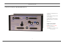
1
PROGRAMMATORE DIGITALE / DIGITAL PROGRAMMED / PROGRAMMEUR DIGITAL / DIGITAL PROGRAMMER
DPS 32C22 VE2V Bus - DPS 32C22 VE3V Bus
MANUALE DI ISTRUZIONI / INSTRUCTION HANDBOOK / MANUEL DE CONDUITE / BETRIBSANWEISUNG
Via Bellini 3 - 40055 Villanova di Castenaso - Bologna - Italy
Tel: 039-51-781185 Fax: 039-51-781273
www.creistt.com e-mail [email protected]
DPS 32C22 VE2-3V Bus
7 . FUNZIONI SPECIALI ................................................... 11
7 . 1 Ciclo di manutenzione .................................................... 11
7 . 2 Conteggio produzione parziale ....................................... 11
7 . 3 Conteggio pezzi di scarto (opzionale) ............................ 11
7 . 4 Chiave esterna (opzionale).............................................. 11
PANORAMICA DEL PROGRAMMATORE…………3
1 . INTRODUZIONE.............................................................. 4
1 . 1 Caratteristiche tecniche del DPS 32C22 VE2-3VBus ...... 4
1 . 2 Caratteristiche tecniche dell‘encoder ............................... 4
1 . 3 Guida al programmatore. .................................................. 5
8 . GUIDA ALLA RICERCA DEI GUASTI ..................... 12
2 . MENÙ SCELTA DELLA LINGUA ................................ 5
3 . MENÙ OROLOGIO.......................................................... 5
4 . MENÙ FUNZIONI ........................................................... 6
4 . 1 Funzione formato in uscita................................................ 6
4 . 2 Funzione anticipo ............................................................. 6
4 . 3 Funzione gradi di sfasamento ........................................... 6
4 . 4 Funzione senso di rotazione.............................................. 7
4 . 5 Funzione limite di velocità ............................................... 7
4 . 6 Funzione rapporto di velocità .......................................... 7
4 . 7 Funzione test camme e test encoder.................................. 7
4 . 8 Azzeramento del contaore e contatore .............................. 7
4 . 9 Selezione formato dall'esterno (PLC o contraves) ........... 8
4 . 10 Gestione II e III encoder ................................................. 8
APPENDICE A ..................................................................... I
Schema dimensionale
APPENDICE B .................................................................... II
schema collegamento encoder programmatore
APPENDICE C ..................................................................... III
Tabella degli anticipi
APPENDICE D ..................................................................... IV
Schema collegamento cavo 232 per comunicazione con PC
APPENDICE E .................................................................... V
Schema collegamento cambio formato da PLC e allarmi da BMS
5 . MENU MESSAGGI........................................................... 8
6 . MENU CAMME ................................................................ 9
6 . 1 Auto apprendimento delle camme .................................... 9
6 . 2 Programmazione camme................................................... 9
6 . 3 Programmazione di più fasi nella stessa camma .............. 10
6 . 4 Cancellazione di una o più fasi della stessa camma ......... 10
6 . 5 Copia di formati già programmati .................................... 11
APPENDICE F...................................................................... VI
Scheda programmi fasi e anticipi
APPENDICE G ..................................................................... VIII
schema collegamento uscite
2
ITALIANO
INDICE
DPS 32C22 VE2-3V Bus
ITALIANO
PANORAMICA DEL PROGRAMMATORE
1) RS232 per comunicazione PC. (Vedi
APPENDICE D)
2) Ingresso segnali per cambio formato da
PLC. (Vedi pag. 8)
3
5
3) Ingresso segnali messaggi d’allarme
all’interfaccia BMS. (Vedi APPENDICE
E)
4) Fuse 0,7A
4
2
1
5) Ingresso encoder assoluto 360
imp./giro da interfaccia BAE/3. Vedi
APPENDICE B)
6) Uscite camme verso interfaccia BPL/32
o interfaccia relé e alimentazione 24 Vdc.
(Vedi APPENDICE G)
6
ATTENZIONE: E’ indispensabile una
corretta messa a terra
3
DPS 32C22 VE2-3V Bus
Questo dispositivo è stato progettato ed industrializzato per generare
ed elaborare dei segnali elettrici di fase necessari al funzionamento di
una qualsiasi macchina automatica. Basandosi sul principio di un
programmatore di camme, invece di usare camme di forma speciale o
regolabili per far funzionare i microinterruttori, i punti di
commutazione
“ON / OFF” desiderati sono programmati con una tastiera.
Definizioni
Camma: funzione che consente di avere segnali ON/OFF sui 360
gradi dell’angolo giro.
1 . 2 Caratteristiche tecniche dell‘encoder
I programmatori vengono forniti solo ed esclusivamente di encoder
assoluti della CREI STT ELETTRONICA. Eventuali difetti o
danneggiamenti derivanti dall’uso d’altri tipi di encoder faranno decadere
ogni forma di garanzia; così dicasi anche per eventuale collegamento
scorretto che potrebbe danneggiare irrimediabilmente l’apparecchiatura.
Albero (diametro): 10 mm standard ( altri diametri a richiesta)
Carico sull’albero: 200N (20,5 Kg) assiale e radiale.
Numero giri/1'(max): 3000 (per periodi brevi 6000)
Momento d’inerzia: 80 g/cm2
Connettore 15 poli: isolamento IP 54
Connettore 19 poli: isolamento IP 65
Temperatura di lavoro: da 0 a +60 gradi C.
Codice binario
Tensione d’alimentazione da +11V a +28V
Assorbimento: 80 - 120 mA
Corrente d’uscita: 30mA
Fase: sezione della camma tra lo stato ON e lo stato OFF seguente. I
punti “ON/OFF” ( in corrispondenza dei quali sulle uscite elettriche si
avranno degli stati “1” ) sono stabiliti in fase di programmazione e
discriminati dal programmatore con una risoluzione di 1 grado.
Formato: configurazione definita da un programma completo di tutte
le camme utilizzate con relative fasi.
Encoder: generatore di impulsi relativi alla posizione angolare
dell’organo di trasmissione sul quale viene montato.
Programmatore: è il dispositivo che riceve gli impulsi dall’encoder e
li elabora secondo il programma impostato (FORMATO).
: indica il pulsante della tastiera usato per confermare i dati
impostati oppure continuare nella selezione.
: Per selezionare o ritornare sui dati precedentemente inseriti.
4
ITALIANO
1 . 1 Caratteristiche tecniche del DPS 32C22 VE2-3VBus
Alimentazione a 24 Vdc
Uscite NPN o PNP. Il carico massimo per ogni uscita è di 80 mA, max
1.2A per banco di 8 camme (NPN max. 50mA).
Autoprotezione sulle uscite da cortocircuito.
Display luminoso a LCD 40 caratteri .
Capacita di memoria: 9 funzioni definite su EEPROM, 180 azioni
ON/OFF per camma per formato o programma (a seconda delle versioni
fino ad un max. di 22 formati o 44 tramite espansione).
Velocità di risposta del dispositivo fino a 8000 giri al minuto. Questa si
riduce se vengono impostati gli anticipi o ritardi
255 messaggi d’allarme macchina programmabili
1 . Introduzione
DPS 32C22 VE2-3V Bus
2 . Menù scelta della lingua
Dalla videata principale, digitare per accedere al menù di scelta della
lingua. A questo punto digitare da tastiera il numero corrispondente alla
lingua desiderata:
FORM 01 ENC1 UNCONN.
T000000000
10:59:26
1 Italiano
4 Tedesco
FORM 01 = Indica il formato impostato in uscita
2 Inglese
5 Spagnolo
3 Francese
3 . Menù orologio
ENC1 UNCONN = Visualizza lo stato del DPS ovvero l’encoder 1 è
scollegato
Dalla videata principale, digitare Clock per accedere al menù timer che
consente d'impostare la data e l’ora. Successivamente digitare :
GRADI o GIRI = Quando l’encoder è collegato visualizza la posizione
angolare o la velocità a cui sta’ girando l’encoder espressa in giri al
minuto nel caso vengano superati i 10 giri al minuto .
Clear per lasciare invariata l ’ impostazione attuale
T 00000000 = Indica il numero progressivo di giri compiuti
dall’encoder.
Può essere utilizzato come conta pezzi con input esterno a richiesta
(vedi Cap 7.2 Funzioni Speciali).
Una volta modificata digitare per confermare. Questa operazione sarà
ripetuta ogni qualvolta si vorrà confermare un dato modificato.
X
per cambiare l’impostazione della data
Digitare da tastiera il numero corrispondente al giorno desiderato
Prima di cominciare la programmazione delle camme è bene
assicurarsi che siano impostati i giusti valori per i parametri delle
funzioni. Per fare ciò si opera da tastiera attraverso 5 menù principali:
1 LUNEDI’
2 MARTEDI’
4 GIOVEDI’
5 VENERDI’
7 DOMENICA
Menù scelta della lingua
Menù timer
Menù funzioni
Menù messaggi
Menù camme
3 MERCOLEDI‘
6 SABATO
Proseguire quindi attraverso il menù in linea fino all'ultima videata,
confermando sempre con Infine per tornare alla videata principale
digitare Clear
5
ITALIANO
1 . 3 Guida al programmatore
DPS 32C22 VE2-3V Bus
Al menù funzioni si accede digitando dalla videata principale. Si
continua poi seguendo le istruzioni in linea fino alla richiesta del
codice ( 4 - 5 - 6 ) .
Una volta entrati si potrà scorrere tutte le funzioni digitando (per
andare avanti o confermare un dato impostato), oppure (per tornare
indietro). Per uscire in qualsiasi momento digitare Clear.
Attenzione : Una volta entrati in questo menù qualsiasi modifica
impostata sarà immediatamente resa effettiva senza alcuna
richiesta di ulteriore conferma. E' quindi consigliabile non rendere
La formula matematica è la seguente:
noto il codice di accesso a personale non addetto.
Dati conosciuti: Giri albero encoder (cicli/1’) , gradi di anticipo necessari
CREI-STT BOLOGNA
Dato
da ricavare: Valore in ms (millisecondi da impostare nel DPS)
A1542: numero di matricola
[ITALY] A1542 P200 A
Cicli/1' / 60 = n (cicli al 1’)
P200A: Software in uso
1000 / n = N ( millisec. per giro)
Prima di entrare nel menù troviamo una videata riepilogativa.
N / 360 = Q (millisec. per grado)
4 . 1 Funzione formato in uscita
Q * Gradi da antic. = T (tempo in millisec. da impostare nel DPS)
Esempio:
FORMATO IN USCITA ?
E' il formato attivo sulle uscite.
Albero encoder = 300 giri/1’
[ 01-22 ] 01
Si imposta solo da questo
Anticipo necessario = 30 gradi
menù.
300 / 60 = 5 cicli/1’
1000 / 5 = 200 millisec per giro
4 . 2 Funzione anticipo
200 / 360 = 0.55 millisec per grado
0.55 * 30 = 16.6 anticipo da impostare sul programmatore
NUMERO ANTICIPI
Selezionare il N° più alto della
Una tabella esemplificativa ricavata con questa formula si trova
[ 01 – 16 ] = 10
cam che si vuole anticipare.
nell'appendice C in fondo al manuale.
4 . 3 Funzione gradi di sfasamento
Una volta impostato il numero desiderato verrà richiesto di digitare il E’ la possibilità di impostare l’angolo di sfasamento tra l’encoder e la
N° della camma da anticipare e un valore di anticipo espresso in macchina. Questo sistema permette, in modo assai rapido, di mettere in
millisecondi. Tale valore può essere trovato attraverso una semplice fase l’encoder con la macchina.
formula matematica (illustrata più avanti) ma che
6
ITALIANO
spesso non risponde alle effettive necessità; questo perché non vengono
considerate variabili che differiscono da macchina a macchina, quali
ritardi o attriti causati da organi meccanici. Tale valore potrà quindi
fornire solo un'indicazione approssimativa. Un sistema più pratico
consiste nel provare per tentativi cominciando da valori piuttosto bassi per
aumentare poi gradatamente fino a trovare il valore corretto. E‘ preferibile
che l’anticipo sia trovato alla massima velocità a cui si intende far andare
la macchina perché possa essere corretto anche alle velocità più basse;
non è invece, sempre vero il contrario.
4 . Menù funzioni
DPS 32C22 VE2-3V Bus
4 . 6 Funzione rapporto di velocità
Questa funzione permette di moltiplicare
RAPPORTO VELOCITA’
il numero di giri dell’encoder
X[1–9] 0=1/3 1
impostando il valore da 0 a 9 dove 0
rappresenta 1/3.
ES.: se tra la macchina A e la macchina B esiste un rapporto di
trasmissione 4/1, e l’encoder è montato sulla macchina B, per avere la
velocità effettiva della macchina A imposterò il valore a 4.
4 . 7 Funzione test camme e test encoder
TEST DELLE CAMM: Permette di
TEST DELLE CAMME = X
effettuare una scansione delle uscite in
4 . 4 Funzione senso di rotazione
ENC=COUNT FINE=CLEAR
Il programmatore ha la
caso si voglia controllare la funzionalità
possibilità di accettare i segnali
dell'impianto finito o dopo un eventuale
SENSO DI ROTAZIONE ?
guasto.
provenienti dall’encoder sia che
ENC1 OR = 0 AOR = 1 0
TEST DELL’ ENCODER : Permette di verificare la funzionalità
vengano trasmessi in senso
dell’encoder o eventualmente del cavo di collegamento. Digitare Enc ed
orario che in senso antiorario.
Da tastiera è possibile impostare il senso di rotazione dell’encoder per effettuare un giro encoder a mano per la scansione di tutti i bit encoder.
avere sempre la visualizzazione incrementale dei gradi.
4 . 8 Azzeramento del contaore e contatore
Questa operazione viene effettuata dal menù funzioni.
4 . 5 Funzione limite di velocità
Dopo aver digitato il codice di accesso appare la videata riepilogativa.
Permette di impostare il limite
Digitare il tasto Clear per accedere
massimo
della
velocità
LIMITE VELOCITA’
RPM = 0000
al contatore e premere X per
dell’albero su cui è montato
CREI-STT BOLOGNA
l’encoder (giri/min) L’utilizzo
azzerare; digitare il tasto Count per
[ITALY] A1542 P200 A
accedere al contaore e premere X
di questa funzione impegnerà
la cam 16 del DPS che andrà in stato di ON ogni qualvolta verrà
per azzerare
superato il limite impostato. Ovviamente se utilizzata per questa Questo menù comprende anche una funzione di cancellazione dei formati.
funzione non dovrà essere usata come le altre camme.
Fare molta attenzione all'uso di questo comando perché queste operazioni
diventano effettive immediatamente senza alcuna richiesta di conferma.
7
ITALIANO
Digitare COUNT se si intende
utilizzare lo zero dell'encoder
(come più logico), quindi uscire
e ruotare l'encoder fino a farlo
coincidere con lo 0 macchina.
A questo punto si stringerà il giunto che si avrà avuto cura di inserire
fra l'albero encoder e l'accoppiamento meccanico. Digitare X se non è
possibile ottenere la corrispondenza di cui sopra. Il programmatore
provvederà automaticamente a calcolarsi i gradi di sfasamento presenti
tra encoder e macchina.
SET ZERO SFASAMENTO
ENC1 COUNT=0 X=SET
DPS 32C22 VE2-3V Bus
4.10 Gestione II e III encoder
Nel caso in cui l’apparecchiatura possa sopportare 2 encoder le
camme da 1 a 16 saranno riservate al primo encoder mentre le
restanti al secondo encoder.
Nel caso possa sopportare 3 encoder le camme da 1 a 16 saranno
riservate al primo encoder, quelle da 17 a 24 al secondo encoder
mentre le restanti al terzo.
All’interno del menù funzioni sono presenti schermate dedicate alla
gestione del secondo e terzo encoder come:
- gli anticipi sul banco di camme da 17 a 20,
- gli anticipi sul banco di camme da 21 a 24,
- il senso di rotazione e lo sfasamento.
Sulla tastiera si accenderanno i led in corrispondenza degli encoder
attivi (B per il secondo e C per il terzo).
Premendo il tasto ENC il display visualizzerà in sequenza lo stato
degli encoder collegati.
Schema di collegamento elettrico
5 . Menu messaggi
I messaggi si caricano sul DPS direttamente da PC con un software
Crei Stt Elettronica fornito in dotazione, la velocità di comunicazione
dovrà essere 9600, N, 8, 1 modificabile premendo il tasto RS232 inserire il cod. di sicurezza, e scorrere con e fino alla
velocità corretta; confermare premendo RS232.
Dalla tastiera digitare Alarm inserire il cod. di sicurezza, per
visualizzare i messaggi caricati e scorrere con le Frecce e .
I messaggi possono essere attivati tramite una basetta (BMS) con
codice binario (ALLEGATO E per i collegamenti).
N.B.: Tutte le funzioni fin qui descritte sono quelle presenti nelle
versioni standard; per eventuali funzioni speciali rivolgersi
direttamente alla Crei Stt Elettronica
8
ITALIANO
4 . 9 Selezione formato dall'esterno (PLC o contraves)
Per poter effettuare il cambio formato da PLC o da contraves è
necessario abilitare il DPS a
riconoscere i segnali provenienti
FORMATO IN USCITA ?
[ 01-22 ] 00
dall’esterno. Per fare ciò bisogna
impostare il formato in uscita dal
menù funzioni con “ 00 “ .
DPS 32C22 VE2-3V Bus
Nel primo caso verranno ripetute le istruzioni dei punti sopra citati.
9
ITALIANO
6 . 2 Programmazione camme
6 . Menu camme
Dalla videata principale, digitando si accede al menù di scelta di
impostazione delle camme o delle funzioni. Digitare ancora per
1 Digitare il numero del formato
SCEGLI IL FORMATO
cominciare la programmazione.
che si desidera programmare,
[ 01-22 ] 01
quindi confermare l'operazione
IMPORTANTE:
digitando .
Ogni operazione effettuata in questo menù non è resa effettiva
2 Se si programma il formato per
CANCELLI FORMATO 01?
immediatamente, come accade per il menù funzioni, ma solo
la prima volta è sempre bene
SI = NO = compiendo un’operazione di salvataggio del lavoro svolto al termine
confermare la cancellazione per
della programmazione (vedremo più avanti). Quindi per uscire senza
sicurezza.
modificare i formati programmati è sufficiente digitare fino a che
FORMATO 01 SCEGLI LA
non si sarà tornati alla videata principale.
3 Digitare il numero della camma
CAM [ 1 – 32 ] 01
che si desidera programmare.
6 . 1 Auto apprendimento della camme
Confermare .
Assicurarsi che l’encoder sia collegato e posizionarsi nel punto in cui
FORMATO 01 CAM 01
inizia la fase; seguire le istruzioni di programmazione delle camme
4 Digitare il grado di inizio fase
CANCELLA CAMSINO
fino al punto 4, quindi digitare il tasto Prod/On, il dato riportato su
(es. 130), confermare il dato .
inizio fase sarà il grado letto dal DPS in quel preciso istante.
Confermare il dato con . Posizionare ora l’albero dell’encoder sul
5 Digitare il grado di fine fase
FORMATO 01 CAM 01
punto in cui finisce la fase e premere il pulsante Reset/Off. Se non si
(es. 160), confermare il dato .
INIZIO/130 FINE\160
desidera fare altre fasi su quella camma confermare con il tasto ,
diversamente premere per ritornare sulla posizione di inizio fase.
6 Scegliere se si desidera
FINE PROGRAMMA
ALTRA CAM
programmare altre camme o si vuole
uscire dalla programmazione.
DPS 32C22 VE2-3V Bus
SCRITTURA IN MEMORIA
[ 01 – 22 ] 01
FORMATO 01 CAM 01
RICERCA FASE 003
9 Selezionare il n° di formato
e confermare premendo .
10 Questa videata compare nel
caso
vi
siano
più
fasi
programmate all’interno della
stessa camma (nel nostro caso 3).
6 . 4 Cancellazione di una o più fasi della stessa camma
Per cancellare una fase all’interno di una camma è sufficiente selezionare
la fase da eliminare, quindi sovra scrivere al grado di fine fase lo stesso
6 . 3 Programmazione di più fasi nella stessa camma
Per ogni camma è possibile programmare più fasi fino ad un massimo valore impostato per il grado d’inizio fase.
di 180. Non è necessario inserirle in un ordine particolare ma verranno
numerate automaticamente dal programmatore in ordine crescente. E` Esempio: Si desidera cancellare la fase N. 2 della camma N. 9
necessario che nella stessa camma non vi siano fasi sovrapposte.
CAMMA 09
fase N. 1 087 - 113
es.
fase N. 1 INIZ. 135 FINE 225
fase N. 2 120 - 142
fase N. 2 INIZ. 212 FINE 260
fase N. 3 227 - 239
fase N. 4 270 – 315
Automaticamente la seconda fase andrà a scriversi come unica fase.
A questo punto la videata 10 illustrerà questa situazione :
10
ITALIANO
Nel secondo caso verrà fatta richiesta di digitare il codice di accesso Operazioni da seguire:
(456) .
Seguire le istruzioni illustrate precedentemente fino al punto 5 senza però
confermare il dato digitando . A questo punto digitare per
posizionare il cursore nuovamente sui gradi di inizio fase andando a
7 Continuare quindi fino alla
riscrivere i gradi di inizio e di fine della seconda fase. Ripetere la
DIGITA IL CODICE
-- -- -fine seguendo le istruzioni
procedura fino a n massimo di 180 fasi, una volta terminato confermare i
guidate.
dati con . Se questi nuovi valori saranno esterni ai primi impostati
(come specificato nell'esempio) avremo creato due fasi. Il numero di fasi
VUOI MEMORIZZARE ?
impostate per ogni camma viene mostrato in una videata prima di entrare
SI = NO = 8 Memorizzare.
nella camma scelta dopo averle memorizzate.
DPS 32C22 VE2-3V Bus
FORMATO 01 CAM 09
RICERCA FASE 004
FORMATO 01 CAM 09
INIZIO/120 FINE\120
Importante: Alle seguenti funzioni si può accedere solo quando il
programmatore si trova nelle condizioni di lavoro normale dalla videata
principale, ovvero quando non si è dentro a nessun menù del tipo camme,
funzioni , lingua, ecc.
quindi scriverò al posto di "142",
"120" confermando il dato con
. In questo modo le fasi
rimaste saranno solo 3 una volta
salvato.
7 . 1 Ciclo di manutenzione
Digitando il tasto Clear viene visualizzato il tempo espresso in ore che la
macchina ha girato.
7 . 2 Conteggio produzione parziale
- Digitando il tasto Prod/On si fa partire il conteggio parziale che viene
indicato sul display da un punto posto dopo la T . 00000000 del contatore
6 . 5 Copia di formati già programmati
- Digitando il tasto Reset/Off si procede con l'arresto, la visualizzazione ed
Questa operazione può essere utile nel caso si debba avere due o più il reset del tempo e dei giri parziali.
formati per i quali solo poche camme differiscono dal formato di base.
Invece di riscrivere tutte quante le camme si può semplicemente 7 . 3 Conteggio pezzi di scarto (opzionale)
copiare un formato in un altro formato operando nel seguente modo :
Digitando il tasto Count si avrà la visualizzazione del numero di pezzi
scartati. Questa funzione viene abilitata con un input dall'esterno nella
Esempio: voglio copiare il formato 3 nel formato 4.
morsettiera Cambio formato da PLC al pin n. 5 . I formati selezionabili
dall'esterno rimarranno quindi 8 avendone sacrificato uno per il
Come prima operazione occorre impostare dal menù funzioni il conteggio.
formato in uscita che si intende duplicare (nel nostro caso il 3).
Entrando quindi nel menù delle camme , alla richiesta di quale formato 7 . 4 Chiave esterna (opzionale)
voglio programmare (videata 1) mi troverò già impostato "03". A Con questa funzione viene impedito l'accesso al DPS a chiunque non sia
questo punto, seguire la procedura indicata nel paragrafo 6.2 fino alla in possesso della chiave. Anche in questo caso viene utilizzato l'ultimo
videata di memorizzazione (videata 9) ed alla richiesta di quale pin della morsettiera Cambio formato da PLC.
formato desidero memorizzare digito "04" , salvando così tutti i dati
del formato N. 3 anche nel formato N. 4.
11
ITALIANO
7 . Funzioni speciali
Da tastiera scriverò al posto di
fase "004", "002" per poter
selezionare la fase da me
prescelta.
DPS 32C22 VE2-3V Bus
N.B. : Le uscite sono autoprotette e l'eventuale guasto (FAIL) viene
segnalato dal LED posto sul frontale del programmatore. Quando si
verifica un corto circuito nelle uscite l'autoprotezione entra in funzione
disabilitando l'uscita stessa.
Per ripristinarla occorre togliere tensione e riparare l'eventuale guasto, a
questo punto ridare tensione e controllarne la funzionalità. Se il led di
FAIL rimane ancora acceso provare a staccare i connettori dell'uscite e
Guasto : Il programmatore non visualizza la corretta posizione togliere tensione per qualche secondo per attendere che gli integrati
autoprotetti si ripristinino. Se ancora il led FAIL non si è spento significa
dell'encoder ma un valore di grado errato.
Verifica : Questo problema può essere causato o da un encoder o da un che un'uscita dell'integrato è stata bruciata.
cavo di collegamento encoder guasti. Verificare quindi uno e l'altro
usando il TEST ENCODER come spiegato nel paragrafo 4.7 pagina 7.
Guasto : Il programmatore non visualizza.
Verifica : Controllare il fusibile del programmatore; se bruciato
verificarne l'eventuale causa e sostituirlo con uno analogo e comunque
non superiore a 700 mA.
Non insistere nella sostituzione dei fusibili ed avvertire il nostro centro
di assistenza.
12
ITALIANO
Guasto : Il programmatore non visualizza la velocità di rotazione corretta
Verifica
: Stessa soluzione del punto sopra
ATTENZIONE : Per precauzione è indispensabile che venga tolta la
tensione all'apparecchiatura prima di inserire o disinserire i
Guasto : Il programmatore non invia segnali in uscita.
connettori flat-cable.
Verifica : Controllare la compatibilità del DPS con l'impianto su cui è
E' opportuno trascrivere sempre le fasi memorizzate e le relative montato e cioè uscite PNP - NPN o relé, e che il collegamento dei flatfunzioni sul manuale (vedi "Scheda Programma" appendice D2) in cable sia corretto. Eseguire quindi il test delle camme dal menù funzioni e
quanto l'eventuale guasto per cause diverse, come la manomissione da verificare la presenza di tutte le uscite. In caso il test non risultasse
inesperti, la sostituzione di memorie o cause alquanto remote che positivo controllare che non vi sia presenza di corti circuito.
dovessero sporcare il programma, potrebbero portare tutte le uscite in
stato OFF (assicurarsi sempre che fonti di disturbo quali elettro- Guasto : Non si riesce a modificare, cancellare o a programmare le
camme .
valvole, ecc., siano protette da RC o varistori).
In tal caso procedere prima alla ricerca dell'eventuale causa che ha Verifica : Il programmatore ha ricevuto un disturbo di tensione. In questo
generato l'inconveniente verificando appunto i filtri antidisturbo, caso è necessario resettare le memorie ed il microprocessore impostando
quindi procedere andando a reimpostare i dati delle funzioni e tutti i parametri del DPS (data e ora, funzioni, scelta della lingua). Prima
di scrivere le camme è accertarsi di aver cancellato tutti i formati.
dell'orologio.
8 . Guida alla ricerca dei guasti
DPS 32C22 VE2-3V Bus
INDEX
1 . MAIN FEATURES ...............................................................4
1 . 1 DPS32 C22 VE2-3 technical specifications ..............4
1 . 2 Technical specifications of the encoder .....................4
1 . 3 Programmer guide ......................................................5
8. TROUBLE SHOOTING ............................................... 12
APPENDIX A ...................................................................... I
Layout drawing
2 . LANGUAGE SELECTION MENU....................................5
3 . TIMER MENU......................................................................5
APPENDIX B ...................................................................... II
Encoder and programmer cable connection diagram
4 . FUNCTION MENU ..............................................................6
4 . 1 Output size .................................................................6
4 . 2 Advances function .....................................................6
4 . 3 Degree offset function ...............................................6
4 . 4 Rotation direction function ........................................7
4 . 5 Speed limit function ..................................................7
4 . 6 Speed ratio function ...................................................7
4 . 7 Cam or encoder test function .....................................7
4 . 8 Reset timer and counter .............................................8
4 . 9 Select external size (PLC or thumb-wheel switches) 8
4 . 10 Management II e III encoder ....................................8
APPENDIX C… .................................................................. III
Advance chart
APPENDIX D ...................................................................... IV
Serial Port cable connection diagram
APPENDIX E ...................................................................... V
Alarm interface BPM cable connection diagram
APPENDIX F ...................................................................... VI
Program table
5. MESSAGE MENU.................................................................8
6. CAM MENU...........................................................................9
6 . 1 Data capture of cam....................................................9
6 . 2 Cam programming......................................................9
6 . 3 Multi phase programming of the same cam ...............10
6 . 4 Delete one or more phases of the same cam...............10
6 . 5 Copy existing size ......................................................11
APPENDIX G ..................................................................... VIII
Output cable connection diagram
2
ENGLISH
7. SPECIAL FUNCTIONS................................................... 11
7 . 1 Maintenance cycle .................................................. 11
7 . 2 Partial production count ......................................... 11
7 . 3 Waste pieces counter (optional) ............................ 11
7 . 4 External key (optional) .......................................... 11
OVERVIEW OF DIGITAL PROGRAMMER………..…2
DPS 32C22 VE2-3V Bus
OVERVIEW OF DIGITAL PROGRAMMER SWITCH
2) Input signals for change size from
PLC. (See page 8)
3
5
3) Input signals for alarm messages
from BMS interface. (See enclosure
E)
4) Fuse 0,7 A
4
2
1
5) Input encoder from BAE/3
interface. (See enclosure B)
6) Output cam and power supply
24Vdc. (See enclosure G)
6
WARNING: It’s essential a correct
earth connection.
3
ENGLISH
1) RS232 for communications. (See
enclosure D)
DPS 32C22 VE2-3V Bus
1 . 1 DPS 32C22 VE2-3 VBus technical specifications
1 . MAIN FEATURES
Comprehension :
Cam : function allowing ON/OFF signals within 360 degrees of a
complete revolution (turn).
Power 24 Vdc
NPN or PNP Output. Each output can supply max. 80mA
Outputs are short circuit protected but not Overload protected.
40 Character LCD display
32 programmable Cams
180 phases for each CAM may be selected
Memory for up to 44 size
Response speed up to 8000 RPM. This speed decreases if
Anticipation is selected.
255 Alarm message selectable
Phase : cam section included between the "ON" condition and the
1 . 2 Technical specifications of the encoder
subsequent "OFF" one.
The "ON/OFF" points (at these points on the electrical output there are The programming units are supplied complete with STT
the condition "1") are determined during the programming phase and ELETTRONICA absolute encoders in any case.
Whatever damage or fault born by other encoder will make void all
chosen by the programmer with one degree resolution .
warranties.
Configuration is defined by a complete program of all used cams, with
The same is for any possible connection that could damage the
relevant phases
equipment irreparably.
Size : pulse generator to be fitted on continuous motion mechanical
Shaft (diameter) : 10mm
members with direct drive.
Load on the shaft : 200N (20.5Kg.) axial and radial
Number of revolution: 3000 max. (for short periods 6000)
Programmer : the unit receives the pulses from the encoder and
Moment of inertia : 80 gcm2
processes them according to the pre-set program (size).
4 pole connector : IP65 insulation
15 pole connector : IP54 insulation
: to confirm the digited or keep on selecting
19 pole connector : IP65 insulation
Working temperature : 0 + 60° C.
: to select or come back to the previously inserted data.
Binary code
Power supply : 8V to 24Vdc.
Absorption : 80 / 120 mA
Output Current : 30mA
4
ENGLISH
This unit has been designed and realised to generate and process
electrical timing signals necessary to run any automatic machine type.
The equipment is based on the principle of a cam programmer; instead
of using special shaped cams or adjustable cams to actuate the micro
witches, the required "ON/OFF" switching points are keyboard
programmed.
DPS 32C22 VE2-3V Bus
1 . 3 Programmer guide
Main display
From the main display, use the key to access the language selection
menu. At this point, type the number which corresponds to the desired
language:
SIZE 1 = Indicates the programmed output format.
1. Italian
ENC1 UNCONN = displays the DPS status, the encoder is 4. German
disconnected.
2. English
5. Spanish
3. French
3 . Timer Menu
DEGREES or REVOLUTIONS = When the encoder is connected,
From the main display, use the Clock key to be able to set the date and
displays the angular position or rotational speed of the encoder in RPM
time. Then use the following keys :
if the speed exceeds 10 turns per minute.
Clock to leave the settings as they are currently.
T 00000000 = Indicates the number of turns completed by the encoder.
This can be used to indicate the piece count with an external input (see
X
to change the date settings.
Chap. 7.2, Special Functions).
Once changed, use the key to confirm. This operation will be used
Before starting to program the Cams, make sure that the Function
whenever a data entry needs to be confirmed.
Parameters are set correctly. To do this, use the keyboard to go through
Type the number which corresponds to the desired day of the week.
the 4 main menus.
1. Monday
4. Thursday
7. Sunday
Language selection Menu
Timer Menu
Function Menu
Message Menu
Cam Menu
2. Tuesday
5. Friday
3. Wednesday
6. Saturday
Continue through the rest of the menus till the last display always confirming
with the key. At the end, use the Clear/Off key to return to the main
display.
5
ENGLISH
SIZE
SIZE0101ENC1
UNCONNECT
UNCONN.
T000000000
10:59:26
T.00000000
15.29
2 . Language selection menu
DPS 32C22 VE2-3V Bus
Use the key to access the Function menu from the main display.
Continue using the On-line instructions until the code (4-5-6) is
requested.
Once in the function menu, the list of functions may be scrolled
forward with the key or backwards with the key. Use the _ key
to confirm any data change. Use the Clear any time to exit the function
menu.
Warning: Once in this menu, any change made will take affect
immediately without it being confirmed. It is good practice
therefore don’t to give the access code to unauthorised personnel.
CREI-STT BOLOGNA
[ITALY] A1542 P200 A
The mathematical formula is as follows:
Known data : Encoder Rotation speed (Cycles/Min),
anticipation/Delay necessary (Degrees)
Value to Find: Value in ms (milliseconds to set on the programmer)
Cycles/Min/60 = n (Cycles/Sec)
1000 / n = N (milliseconds/Revolution)
N / 360 = Q (milliseconds/degree)
Q x Degrees of Advances = T (time in milliseconds to set on the
programmer)
A1542 : Serial number
P200A : Software being used
Before entering the menu, general summary information is displayed.
4 . 1 Output Size
SIZE OUTPUT ?
[ 01 - 22 ] 00
This is the active size on the
outputs once the functions setup has been completed. It can
only be set from this menu.
Example:
Encoder shaft = 300 Turns/Min
Advances Required = 30 Degrees at max. speed
300 / 60 = 5 Cycles/Sec.
1000 / 5 = 200 milliseconds/turn
200 / 360 = 0.55 milliseconds per degree
0.55 x 30 = 16.6 (anticipation time to set on the programmer)
4 . 2 Advances Function
NUMBER ADVANCES
[ 01 - 16 ] 00
Select the higher number of
cam do you want to advance.
A simplified table calculated using the above formulas can be found in
appendix ‘C’ at the end of the manual.
6
ENGLISH
Once the advances sets has been selected, the programmer will require
an advances value in Milliseconds .This value can be found in practice
or with a simple mathematical formula (illustrated later on) but may
not correspond to the true requirements. Because none variables are
taken into consideration, which are different for each machine as
delays or frictions caused by mechanical parts.
A more practical way is by starting with a very low value and
gradually increasing it until the correct value is found. It is preferable
that the advanced value is found at the maximum speed for the
machine. This assures that the value will work correctly even at the
low speeds.
4 . Function menu
DPS 32C22 VE2-3V Bus
4 . 6 Speed ratio function
4 . 3 Degree Offset Function
This feature permits one unit to
control more than one machine at the
same time reserving a part of the
programmer for the In-line machines
having different ratios. If the retards functions is not used, two sets of
encoder with the machine.
Type Count if you wish to use the encoder Zero-Mark (a logical use). eight cams may be dedicated each with its ratio.
Then exit and rotate the encoder shaft until it coincides with machine’s
“0” point. At this point, tighten the encoder coupling between the The standard ratios are:
1/1; 2/1; 3/1; 4/1; 5/1; 6/1; 7/1; 8/1; 9/1
encoder shaft and the mechanical joint to fix the encoder position.
Type in X if it is not possible to obtain a correspondence as described
In this case, the encoder will be fitted to the machine with the highest
above.
The programmer will automatically calculate the offset degrees speed. For a quicker and more precise programming of the unit, it is
advisable to dispose of two phase disks (360 degrees). One fitted to the
between the encoder with the machine.
fast shaft and the other on the slower shaft. The disks must then be
4 . 4 Rotation Direction Function
phased (0/0) to establish the cycle start position. Only when the zeros
The programmer accepts the
correspond, the first revolution set may be carried out. Where a
encoder signals in both
REVOLUTION DIRECT.?
ENC1 OR=0 AOR=1 0
constant ratio is necessary, it’s appropriate to use a sensor on the
clockwise and anticlockwise
slower ratio side which gives a “0” (RESET) signal to the programmer
directions. The keyboard can be
in order to re-phase as soon as the common “0” is passed.
used to set the
rotation direction so the display will always show an incremental
value.
4 . 7 CAM or Encoder Test Function
4 . 5 Speed Limit Function
Gives the possibility to set a
CAM TEST: This gives the
TEST CAMS = X
maximum shaft rotation speed
possibility to test the Cam
SPEED LIMIT
ENC=COUNT END=CLEAR
(RPM). This option dedicates
outputs. This is useful after
RPM = 0000
the 16th DPS Cam to be used
machine installation or for
as an output indicator that the
diagnosing an eventual problem
set rotation speed has been
situation.
exceeded.
Obviously, if this Cam is used for this purpose, it cannot be used ENCODER TEST: Used to verify the Encoder functioning or its
normally.
connecting cable .Type in 7 and make one rotation handle to test the bit
encoder. The display will show encoder OK or FAULT.
SET ZERO PHASE DISPL.
ENC1 COUNT=0 X=SET
Gives the possibility to input the
offset degrees between the encoder
and the machine. This gives the user
a quick method of phasing the
SPEED RATIO ?
X [1–9] 0=1/3 1
ENGLISH
7
DPS 32C22 VE2-3V Bus
4 . 8 Reset Timer and Counter
4 . 10 Management II e III encoder
5 . Message menù
Messages are loaded directly from DPS on a PC with software supplied
CREI STT Electronica, the communication speed will be 9600, N, 8, 1
changed by pressing RS232 the enter code security, and scroll
with and until the correct speed and confirm by pressing RS232.
Type from the keyboard Alarm the enter code security, to show
the loaded messages into display and scroll with the arrows and Messages can be activated by a base (BMS) with a binary code (see
Enclosure E for connection).
NB: All the functions described above are installed in standard version;
for any special features contact directly CREI STT Electronica
8
ENGLISH
In the event that the DPS can supports 2 encoders the cams from 1 to
16 will be reserved for the first encoder and the remaining in the
second encoder.
In the event that the DPS can supports 3 encoders the cam from 1 to 16
will be reserved for the first encoder, those 17 to 24 per second
encoder and the remaining third.
Inside the function menu, screens are dedicated to the management of
the second and third encoders as:
- advances on the cam 17 to 20,
- advances on the cam 21 to 24,
- the direction of rotation and phase shift.
4 . 9 Select external size (PLC or Thumb-wheel Switches)
On the keyboard Leds light up in correspondence with the encoder
In order to change formats from a PLC or Thumb-wheel switches, the active (B and C for the second to the third).
DPS must be enabled to recognise external signals. To do this, the Pressing the ENC key display will show the sequence of the state of the
encoder connected.
output format must be set from the function menu with “00”.
Electrical connection diagram
This operation is activated from the function menu.
After inputting the access code, the general display is shown:
At this point use the Clear key to
CREI-STT BOLOGNA
reset the timer, press X to reset;
[ITALY] A1542 P200 A
For reset the counter use Count
key and press X.
This menu also includes a delete function in different formats. Be very
careful when this command because these operations are effective
immediately without any prompting.
DPS 32C22 VE2-3V Bus
6 . 2 Cam Programming
6. Cam Menu
CHOOSE SIZE
[ 01-22 ] 01
ATTENTION:
The operations performed in this menu do NOT take effect
immediately like they do in the Function menu. They take effect only
after the work is completed with a save operation (as we will see later
on). Therefore, to exit without saving the programmed formats, use the
key till the main display is reached.
DELETE SIZE 01?
YES = NO = SIZE 01 CHOOSE
CAM [ 1 – 32 ] 01
1 Type in the size number to program
and then confirm the operation with
the key.
2 If the size is being programmed for
the first time, it is good practice to
confirm the deletion.
3 Type in the Cam number to program
and confirm with the key.
4 Type in the Phase start degrees
(E.g.130) and confirm with the key.
6 . 1 Data Capture of cam
SIZE 01 CAM 01
DELETE CAM YESNO
Make sure the encoder is connected and positioned at the point where
phase begins, follow the programming instructions to the point of the
cam 4, and then type the key Prod / On, the data reported in the starting
stage can be read by the DPS in that precise moment.
With confirmed result. Now position the encoder shaft to the point
where the stage ends and press the Reset / Off. If you do not want to do
other steps to confirm with unlike press to return to the starting
position phase and repeat the procedure.
SIZE 01 CAM 01
START/130 END\160
PROGRAM END OTHER CAM 5 Type in the Phase end degrees
(E.g.160) and confirm with the key.
6 Select whether to program another
Cam or to exit the programming mode.
If another Cam program is selected, all
the above steps will be repeated. If
programming is ended, the Access
code (4 5 6) is requested to confirm
that the programmed data are to be
saved.
If the new phase values are not within the other phase values (as
indicated in the example), then 2 different phases are pre
programmed. The number of different phases programmed is
displayed before entering the selected cam after saving it.
9
ENGLISH
Using the key from the main display, the Function menu or the Cam
programming functions are accessed. Use the key again to start
programming.
DPS 32C22 VE2-3V Bus
DIGIT CODE
-- -- --
7 Continue following
instructions till completion
SIZE 01 CAM 09
PHASE SEARCH 004
the
10 This screen shows how many
phases are into a cam, does not
appear when a cam is programmed
for the first time.
WRITING STORED ?
[ 01-22 ] 01
8 Store
6 . 4 Delete one or more phases of the same CAM
To delete a phase from a cam, it is sufficient to select the phase to
eliminate and set the phase end value equal to the phase start value.
9
Select size end press to
confirm
Example: If phase # 2 has to be eliminated from cam # 9;
CAM # 09
Phase #1 087 - 113
Phase #2 120 - 142
Phase #3 227 - 239
Phase #4 270 – 315
6 . 3 Multi Phase programming of the same CAM
Each cam can be programmed with as many as 180 different phases. Its
not necessary to program the phases in any particular order. The
programmer will reorder the phases sequentially. There must NOT be
any overlapping phases in the list.
Screen .10 will display the following:
E.g.
Phase #1
Phase #2
Start: 135
Start: 212
End: 225
End: 260
SIZE 01 CAM 09
PHASE SEARCH 004
The second phase selected will automatically be programmed as the Use the keyboard to select the phase to delete by typing “002” in place
only phase with the start of the 2nd and the end of the 2nd phase.
of “004”.
Operations to perform:
Follow the previous instructions till step #5 without using the key to
confirm. Instead use the key to place the cursor in the Phase start
field again and type in a new start phase
10
ENGLISH
MEMORY ?
NO
YES
DPS 32C22 VE2-3V Bus
SIZE 01 CAM 09
START/120 END \142
Type in “120” in place of “142”
for the Phase end degrees and
confirm with the key. At this
point, only 3 phase will remain
once saved.
7. Special Functions (Key function)
6 . 5 Copy existing Size
This function is useful in case a size is needed where the cam program 7 . 1 Maintenance Cycle
differs very little from the base size.
Typing the 7 key will display the working hours of the machine.
Instead of rewriting all the cam information, simply copy an existing
size to a new size as follows:
7 . 2 Partial Production Count
- Typing the 8 key will start the partial production counter which is
Example: Copy size 3 to new size 4.
identified by the dot after the T. 00000000 counter.
- Typing the 9 key will stop the counter, display it, and reset its
As the first operation, select the size to be copied from the function contents.
menu (in this case, 3).
Then enter in the cam menu and at the request of which size has to be 7 . 3 Waste pieces counter (Optional)
programmed (screen .1), the value “03” will already be set. Follow the Typing the 4 key will display the waste piece count. This function is
steps described into paragraph 6.2 since screen 9 . Answering “04” at enabled by using an external input terminal #5 from the PLC Format
this point, will save all the contents of size “03” to the new format Change. Having used one input for this function, the externally
“04”.
selectable formats available are now 8.
7 . 4 External Key (Optional)
This security feature assures that only authorised personal with the key
may access the DPS. This function uses the last input terminal from the
PLC Format Change.
11
ENGLISH
ATTENTION: These functions may only be accessed when the
programmer is in normal working mode and at the main screen. In
other words, the programmer must not be in any of the following
menus; cam, functions, languages, etc.
DPS 32C22 VE2-3V Bus
Check Control that the programmer is compatible with the output
stages
(PNP, NPN, Relays) and the flat cables are connected correctly.
WARNING: As a precaution, it is absolutely necessary that the power
to the programmer is off before connecting or disconnecting the flat Use the CAM TEST function to control all the outputs. If it still does
not work properly, then check for the possibility of any short circuits.
cables.
It is good practice to copy the phase programs in memory and their
relative functions in the manual (see “Program Table” appendix D2) in Fault The operator can't modify, delete or write new cam on the
case of mishandling by inexperienced personal, or memory loss caused Programmer
by electrical noise from solenoids, etc.
In these cases, first proceed to find the probable cause such as a bad Check The programmer must be resetting cause a wrong tension or a
RC filter. Then re-input the function data and set the Clock. .This noise effect. In this case the operator must rewrite all the parameters of
the
operation will reset any wrong data in the RAM memory.
programmer (timer, functions, and language selection). Before rewrite
the new cam program, delete all old size .
Fault The programmer display does not work.
8. Trouble Shooting
Check See previous problem.
Fault The programmer does not activate the outputs.
12
ENGLISH
Check Control the main fuse and if burned-out, verify the cause before
replacing it. Substitute the fuse with a similar type but not greater than
NB: The outputs are short circuit protected. The LEDS on the front of
700mA. If the fuse keeps burning-out, please contact us.
the programmer evidence any eventual fault (FAIL). If a short circuit
occurs, the protection circuit automatically disables the outputs.
Fault The programmer displays the wrong encoder position.
To reactivate them, switch power off and then switch on again after the
Check This problem may be caused either by a faulty encoder or short circuit has been removed. If the FAIL LEDS still come on, turn
encoder connection cable .Verify the problem by using the ENCODER power off, remove the output connector and wait a few seconds before
reconnecting and turning power back on again. This gives the
TEST function described in section 4.8 pg.4
protection circuit time to reset itself. If the FAIL LEDS still come on,
means that one of the outputs from the driver circuit has burned out.
Fault The programmer displays the wrong rotation speed.
DPS 32C22 VE2-3V Bus
SOMMAIRE
VUE D'ENSEMBLE DES PROGRAMMEUR…...…........…3
7 . FONCTIONS SPECIALES .................................................11
7 . 1 Cycle de maintenance ......................................................11
7 . 2 Comptage partiel de production...........................................11
7 . 3 Comptage des pièces mises au rebut (en option) .................11
7 . 4 Cle externe (en option).........................................................11
1 . INTRODUCTION..................................................................... 4
8 . GUIDE DE RECHERCHE DES PANNES ........................12
2 . MENU DE SELECTION DE LA LANGUE .......................... 5
3 . MENU HORLOGE................................................................... 5
4 . MENU DES FONCTIONS....................................................... 6
4 . 1 Format de sortie ....................................................................... 6
4 . 2 Fonction avance ....................................................................... 6
4 . 3 Fonction degrés de des phasage ............................................... 7
4 . 4 Fonction sensé de rotation ....................................................... 7
4 . 5 Fonction limite de vitesse ........................................................ 7
4 . 6 Fonction rapport de vitesse ...................................................... 7
4 . 7 Fonction test de cames et test de l’encodeur............................ 7
4 . 8 Remise a zero du compte-heures et du compteur ................... 7
4 . 9 Sélection du format de l’extérieur (PLC ou contraves) ........... 8
4 . 10 Management 2e et 3e encodeur............................................... 8
PIECE JOINTE A .....................................................................I
Schéma des dimensions
PIECE JOINTE B .....................................................................II
Connexions encoder - programmeur
PIECE JOINTE C .....................................................................III
Tableau avancé
PIECE JOINTE D .....................................................................IV
Connexions computer – programmeur
PIECE JOINTE E .....................................................................V
Connexions interface d’alarme – programmeur
5 . MENU DES MESSAGE ........................................................... 8
6 . MENU CAMES......................................................................... 9
6 . 1 Auto apprentissage des cames ................................................. 9
6 . 2 Programmation cames ............................................................. 9
6 . 3 Programmation de plusieurs phase sous une même came ....... 10
6 . 4 Effacement d’une ou de plusieurs phases d’une même came.. 10
6 . 5 Copie de formats déjà programmes ......................................... 11
PIECE JOINTE F......................................................................VI
Carte de programmations
PIECE JOINTE G .....................................................................VIII
Connexions sortie
2
FRANCAIS
1 . 1 Caractéristiques techniques du DPS 32C22 VE2-3VBus ........ 4
1 . 2 Caractéristiques techniques de l’encodeur............................... 4
1 . 3 Guide d’utilisation du programmateur..................................... 5
DPS 32C22 VE2-3V Bus
VUE D'ENSEMBLE DES PROGRAMMEUR
2) Entrée signaux pour changement format
depuis PLC. (voir page 8)
3
FRANCAIS
1) RS232 pour communication PC (voir
PIECE JOINTE D)
5
4) Fusible 0,7A
4
2
1
5) Entrée encodeur absolu 360 imp./tour à
l'interface BAE/3 (voir PIECE JOINTE B)
6) Sorties cames vers interface BPL/32 ou
interface relais et alimentation 24 Vdc.
(voir PIECE JOINTE G)
6
ATTENTION: il est indispensable de
mise à la terre
3
FRANCAIS
3) Entrée signaux pour changement format
depuis PLC et messages d’alarme à
l'interface BMS. (voir PIECE JOINTE E)
DPS 32C22 VE2-3V Bus
Ce dispositif a été conçu et industrialisé pour générer et traiter des
signaux électriques de phase nécessaires au fonctionnement d’une
machine automatique quelconque. Se basant sur le principe d’un
programmateur de cames, au lieu d’utiliser des cames de forme
spéciale ou réglables pour faire fonctionner les micro interrupteurs, les
points de commutation “ON / OFF” désirés sont programmés par
clavier.
Définitions :
came: Fonction permettant d’obtenir des signaux ON/OFF sur un
angle plein de 360 degrés.
phase: Section de la came entre l’état ON et l’état OFF suivant. Les
points “ON/OFF” (auxquels correspondront, sur les sorties électriques, 1 . 2 Caractéristiques techniques de l’encodeur
des états “1”) sont établis lors de la programmation et discriminés par Les programmateurs sont équipés uniquement d’encodeurs absolus de
Crei Stt Elettronica. Les éventuels défauts ou dommages résultant de
le programmateur avec une résolution de 1 degré.
l’utilisation d’autres types d’encodeur entraînent l’annulation de toute
Format: Configuration définie par un programme comprenant toutes forme de garantie; il en est de même pour toute éventuelle mauvaise
liaison pouvant endommager irrémédiablement l’appareil.
les cames utilisées, avec leurs phases.
Arbre (diamètre) : 10 mm standard (possibilité d’autres
diamètres sur demande)
Encodeur: Générateur d’impulsions concernant la position angulaire
Charge sur l’arbre : 200N (20,5 Kg) axiale et radiale.
de l’organe de transmission sur lequel il est monté.
Nombre de tours /mn (maxi) : 3000 (pour des périodes courtes
6000)
Programmateur: C’est le dispositif qui reçoit les impulsions
Moment d’inertie: 80 g/cm2
provenant de l’encodeur et les traite selon le programme établi
Connecteur 19 pôles : isolation IP 65
(FORMAT).
Température de travail : de 0 à +60 degrés C.
Code binaire
: Indique la touche du clavier pour valider les données introduites
Tension d’alimentation : de +11V à +28V
ou bien continuer la sélection.
Absorption : 80 - 120 mA
: Pour sélectionner ou retourner aux données introduites
Courant de sortie : 30mA
précédemment.
4
FRANCAIS
1 . 1 Caractéristiques techniques du DPS 32C22 VE2-3VBus
Alimentation 24 Vdc
Sorties NPN ou PNP. La charge maximale pour chaque sortie est
de 50 mA. Elles sont auto protégées contre les courts-circuits
mais pas contre les surcharges.
Afficheur lumineux à LCD 20x2 caractères
32 cames programmables
180 phases programmables pour chaque came
Jusqu’à 44 formats mémorisables
180 messages d’alarme programmables par PC
Vitesse de réponse jusqu’à 8000 tours/minute. Cette vitesse
diminue si l’on programme les avances (1000 tours/minute).
1 . INTRODUCTION
DPS 32C22 VE2-3V Bus
1 . 3 Guide d’utilisation du programmateur
SIZE 01 ENC1 UNCONN.
T000000000
10:59:26
2 . Menu de sélection de la langue
Dans la page-écran principale, taper pour accéder au menu de
sélection de la langages. Tapes alors au clavier le numéro correspondant
à la langue désirée:
écran principal
1 Italien
4 Allemand
2 Anglais
5 Espagnol
ENC1 UNCONNECT = Affiche l’état du DPS, c’est-à-dire que
l’encodeur est débranché
3 . Menu horloge
3 Français
Dans la page-écran principale, taper Clock pour accéder au menu horloge
qui permet de programmer la date et l’heure. Taper ensuite :
DEGRES ou TOURS = Quand l’encodeur est branché, il affiche la
position angulaire ou la vitesse à laquelle il tourne, exprimée en
tours/minute en cas de vitesse supérieure à 10 tours/minute.
Clear pour garder la programmation courante
X
T 00000000 = Indique le nombre progressif de tours accomplis par
l’encodeur. Il peut être utilisé comme compteur de pièces avec sortie
externe sur demande (voir Chap. 7.2 Fonctions Spéciales)
pour changer la programmation de la date
Après avoir effectué la modification, taper pour valider.
Il sera nécessaire de refaire cette opération toutes les fois que l’on veut
valider une donnée modifiée.
Avant de commencer la programmation des cames, il convient de
vérifier si les valeurs établies pour les paramètres des fonctions sont
correctes. Pour ce faire, on agit au clavier à travers 5 menus
principaux:
Taper au clavier le numéro correspondant au jour désiré
1 LUNDI
2 MARDI
4 JUEDI
5 VENDREDI
7 DIMANCHE
Menu de sélection de la langue
Menu horloge
Menu des fonctions
Menu des messages
Menu des cames
3 MERCREDI
6 SAMEDI
Continuer ensuite à travers le menu en lingue jusq’à la dernière pageécran, en validant toujours par.
Enfin, pour quitter et retourner à la page-écran taper Clear
5
FRANCAIS
FORM 1 = Indique le format de sortie sélectionné.
DPS 32C22 VE2-3V Bus
L'avance est exprimée en ms. On peut trouver cette valeur dans la
pratique ou par une simple formule mathématique (que l’on montrera
plus loin) mais qui pourrait ne pas répondre aux besoins réels; ceci étant
dû au fait que les variables qui diffèrent d’une machine à l’autre, telles
que les retards ou les frottements causés par les organes mécaniques ne
sont pas prises en compte. Cette valeur ne pourra donc fournir qu’une
indication approximative. Un système plus pratique consiste à faire des
tentatives en commençant par des valeurs plutôt basses puis en
augmentant progressivement jusqu’à trouver la bonne valeur. Il est
Attention : Une fois entrés dans ce menu, toute modification préférable de trouver l’avance à la vitesse maximale à laquelle on veut
introduite sera immédiatement effective sans que le programme faire fonctionner la machine pour qu’il soit possible de la corriger
demande de valider ultérieurement. Il est donc conseillé de ne pas également aux vitesses plus basses.
communiquer le code d’accès au personnel non autorisé.
La formule mathématique est la suivante:
Données connues :
Avant d’entrer dans le menu, on voit apparaître une page-écran
- Tours arbre encodeur (cycles/mn) ; Degrés d’avance ou de retard
récapitulative.
nécessaires
CREI-STT BOLOGNA
A1542 : N° de série
Donnée à calculer:
[ITALY] A1542 P200 A
- Valeur en ms (millisecondes à fixer sur le programmateur),
P200A: programme utilisé
Cycles/mn / 60 = n (cycles/mn),
1000 / n = N ( millisecondes par tour),
4 . 1 Format de sortie
N / 360 = Q (millisecondes par degré),
C’est le format qui sera actif sur
Q * Degrés d’avance = T (temps en millisecondes à fixer sur le
les sorties une fois la
programmateur),
FORMAT SORTANT ?
programmation des fonctions
[ 01 – 22 ] 00
Exemple:
terminée. On ne peut le
Arbre encodeur = 300 tours/mn ; Avance nécessaire = 30 degrés
programmer que dans ce menu.
300 / 60 = 5 cycles/mn ; 1000 / 5 = 200 millisecondes par tour
200 / 360 = 0.55 milliseconde par degré
4 . 2 Fonction avance
0.55 * 30 = 16.6ms d’avance à fixer sur le programmateur
Sélectionnez le plus grand
NEMBER AVANCES
nombre de cam que nous
Un tableau simplificateur calculé d’après cette formule se trouve dans
[ 01 – 16 ] 01
voulons anticiper.
l’annexe C à la fin du manuel.
4 . Menu des fonctions
On accède au menu des fonctions en tapant dans la page-écran
principale. Continuer ensuite selon les instructions en ligne jusqu’à ce
que le programme demande d’introduire le code ( 4 - 5 - 6 ) . Une fois
entrés, il est possible de parcourir toutes les fonctions en tapant (pour passer à la fonction suivante ou pour valider une donnée
introduite) ou bien (pour revenir à la fonction précédente). Pour
quitter le menu à tout moment, taper Clear.
FRANCAIS
6
DPS 32C22 VE2-3V Bus
4 . 6 Fonction rapport de vitesse
Etablir une valeur (1-4) servant de
RAPPORT DE VITESSE
multiplicateur du nombre de tours de
X [ 1 – 9 ] 0 = 1/3 1
l’arbre sur lequel est monté l’encodeur.
Ex.: entre la machine A et la machine B, il existe un rapport de
transmission 4/1 et l’encodeur est monté sur la machine B ; pour faire
afficher la vitesse de la machine A, établir la valeur « 4 »
4 . 3 Fonction degrés de déphasage
Cette fonction permet de programmer l’angle de déphasage entre
l’encodeur et la machine. Ce système permet, de façon rapide, de
synchroniser l’encodeur avec la machine.
Taper Count si l’on veut utiliser
SET DE PHASAGE
le zéro de l’encodeur (solution
ENC1 COUNT=0 X=SET
la plus logique), puis quitter et
les compteurs.
Type comte la clé pour accéder au compteur et appuyez sur X pour
Permet d’établir la limite
effacer
LIMITE VITESSE
maximale de la vitesse de
Ce menu comprend également une fonction de suppression dans
TPM = 0000
l’arbre sur lequel est installé
différents formats. Soyez très prudent lorsque vous utilisez cette
l’encodeur (tours/mn)
commande parce que ces opérations entrent en vigueur immédiatement et
L’utilisation de cette fonction concernera la 16 came du DPS qui spontanément.
passera à l’état ON chaque fois que la limite établie sera dépassée.
Bien entendu, si elle est utilisée pour cette fonction, elle ne devra pas
être utilisée comme les autres cames.
4 . 5 Fonction limite de vitesse
7
FRANCAIS
tourner l’encodeur jusqu’à ce qu’il coïncide avec le 0 de la machine. Il 4 .7 Fonction test des cames ou test de l’encodeur
est alors nécessaire de serrer le joint que l’on veillera à placer entre
TEST
DES
CAMES:
Permet
l’arbre de l’encodeur et le couplage mécanique.
TEST CAMES = X
d’effectuer un balayage des sorties si
Taper X s’il n’est pas possible d’obtenir la correspondance ci-dessus.
ENC=COUNT FIN=CLEAR
l’on
veut
contrôler
le
bon
Le programmateur calculera automatiquement les degrés de déphasage
fonctionnement de l’installation finie ou
existant entre l’encodeur et la machine.
après une panne éventuelle.
TEST DE L’ENCODEUR: Permet de vérifier le bon fonctionnement de
4 . 4 Fonction sens de rotation
l’encodeur et, éventuellement, du câble de liaison.
Le
programmateur
peut
accepter les signaux provenant
SENSE DE ROTATION ?
4 . 8 Remise à zéro du compte-heures et du compteur
de l’encodeur, qu’ils soient
ENC1 OR=0 AOR=1 0
Cette opération s’effectue dans le menu des fonctions.
transmis dans le sens des
Après avoir tapé le code
aiguilles d’une montre ou dans le sens inverse. Au clavier, il est
CREI-STT BOLOGNA
d’accès,
la
page
écran
[ITALY] A1542 P200 A
possible d’établir le sens de rotation de l’encodeur pour avoir toujours
récapitulative apparaît. Taper
l’affichage incrémentiel des degrés.
alors la touche Clear pour vider
DPS 32C22 VE2-3V Bus
Pour
pouvoir
effectuer
le
changement de format depuis
l’automate
programmable (PLC) ou le présélecteur “contraves”, il est nécessaire
de prédisposer le DPS pour reconnaître les signaux provenant de
l’extérieur. Pour ce faire, établir le format de sortie dans le menu des
fonctions à “00“.
FORMAT SORTANT ?
[ 01 – 22 ] 00
Schema de liaison électrique
5 . Menu Messages
Les messages se chargent sur le DPS directement du PC à l’aide du
logiciel Crei Stt Elettronica fourni avec la machine. La vitesse de
communication doit être de 9600, N, 8, 1. Pour la modifier, appuyer sur
la touche RS232 saisir le code de sécurité et défiler par et jusqu’à atteindre la vitesse correcte. Confirmer en appuyant sur RS232.
Sur le clavier, appuyer sur Alarm saisir le code de sécurité pour
afficher les messages chargés et défiler par les flèches et .
Les messages peuvent être activés par une base (BMS) avec un code
binaire (ANNEXE E pour les branchements).
Nota : toutes les fonctions décrites ci-dessus sont les fonctions présentes
dans les versions standard ; pour toute fonction spéciale contacter
directement la société Crei Stt Elettronica.
8
FRANCAIS
4 . 10 Management 2e et 3e encodeur
Si la machine peut supporter 2 encodeurs, les cames de 1 à 16 seront
réservées au premier encodeur, tandis que les autres seront réservées au
deuxième encodeur.
Si la machine peut supporter 3 encodeurs, les cames de 1 à 16 seront
réservées au premier encodeur, les cames de 17 à 24 au deuxième
encodeur et celles qui restent au troisième.
Dans le menu Fonctions il est présent des pages-écrans dédiées à la
gestion du deuxième et du troisième encodeur :
- les avances sur la bande des cames de 17 à 20,
- les avances sur la bande des cames de 21 à 24,
- le sens de rotation et l’écart.
Sur le clavier les voyants s’allument selon les encodeurs actifs (B pour le
deuxième et C pour le troisième).
Lorsque l’on appuie sur la touche ENC, l’afficheur affiche, en séquence,
l’état des encodeurs reliés.
4 . 9 Sélection du format de l’extérieur (PLC ou “contraves”)
DPS 32C22 VE2-3V Bus
6 . 2 Programmation Cames
6 . Menu Cames
Dans la page-écran principale, en tapant on accède au menu du
choix de programmation des cames ou des fonctions. Taper encore pour commencer la programmation.
CHOISIR LE FORMAT ?
[ 01 – 22 ] 001
EFFACES LE FORMAT 01?
OUI = NON = FORMAT 01 CHOISER
LA CAM [ 01 – 32 ] 01
FORMAT 01 CAM 01
EFACES CAM OUINON
6 . 1 Auto apprentissage de la came
S’assurer que l’encodeur soit relié et se placer là où la phase
commence. Suivre les instructions de programmation des cames
jusqu’au point 4, puis appuyer sur la touche Prod/On. A ce moment-là,
la donnée, reportée sur le début de la phase, sera lue par le DPS.
Confirmer la donnée par . Placer l’arbre de l’encodeur là où la phase
se termine et appuyer sur le bouton Reset/Off. Si l’on ne souhaite pas
faire d’autres phases sur cette came, confirmer par la touche , sinon,
appuyer sur pour revenir à la position de début de phase.
FORMAT 01 CAM 01
DEBUT /130 FIN \160
FIN PROGRAMME AUTRE CAME 4 Taper le degré de début de
phase (ex. 130), valider par 5 Taper le degré de début de
phase (ex. 160), valider par .
6 On peut alors choisir de
programmer d’autres cames ou
de quitter la programmation.
Dans le premier cas, les instructions indiquées aux points ci-dessus seront
répétées.
9
FRANCAIS
IMPORTANT :
Toute opération effectuée dans ce menu n’est pas immédiatement
effective, comme c’est le cas pour le menu des fonctions, elle ne le
devient que si l’on effectue une opération de sauvegarde du travail
réalisé à la fin de la programmation (voir plus loin). Donc, pour quitter
le menu sans modifier les formats programmés, il suffit de taper jusqu’à ce qu’on retourne à la page-écran principale.
1 Taper le numéro du format
que l’on désire programmer,
puis valider l’opération en tapant
.
2 Si l’on programme le
format pour la première fois, il
convient toujours de valider
l’effacement, par mesure de
sécurité.
3 Taper le numéro de la
came
que
l’on
désire
programmer. Valider par .
DPS 32C22 VE2-3V Bus
Dans le deuxième cas, le programme demande de taper le code d’accès
(4 5 6) pour pouvoir enregistrer la programmation effectuée.
DIGITALISER LE CODE
-- -- --
ECRITURE EN MEMERIE
[ 01 – 22 ] 01
7 Continuer ensuite jusqu’à la fin
selon les instructions guidées.
8 Emmagasiné
FORMAT 01 CAM 01
RECERCHE PHASE 003
9 Sélectionnez le format
6 . 3 Programmation de plusieurs phases sous une même came
10 Cette page-écran apparaît
si il écran plusieurs étapes
prévues dans le même came
(dans notre cas 3).
6 . 4 Effacement d’une ou de plusieurs phases d’une même came
Pour effacer une phase à l’intérieur d’une came, il suffit de sélectionner
Pour chaque came, il est possible de programmer plusieurs phases la phase à éliminer, puis de remplacer le degré de fin de phase par la
jusqu’à un maximum de 180. Il n’est pas nécessaire de les introduire même valeur que celle établie pour le degré de début de phase.
dans un ordre particulier mais elles seront automatiquement
numérotées en ordre croissant par le programmateur. Par contre, il est Exemple: On désire effacer la phase N° 2 de la came N° 9
nécessaire qu’il n’y ait pas de phases superposées dans une même
came.
CAME 09
phase N. 1 087 - 113
ex.
phase N° 1 DEBUT 135 FIN 225
phase N. 2 120 - 142
phase N° 2 DEBUT 212 FIN 260
phase N. 3 227 - 239
phase N. 4 270 – 315
Dans ce cas, la deuxième phase sera automatiquement inscrite comme
l’unique phase.
La page-écran 10 montrera alors cette situation:
10
FRANCAIS
MISE EN MEMORIE
OUI = NON = Opérations à effectuer:
Suivre les instructions indiquées précédemment jusqu’au point 5, mais
sans valider la donnée par . Taper alors pour positionner de
nouveau le curseur sur les degrés de début de phase, allant réécrire ainsi
une nouvelle phase. Si ces nouvelles valeurs sont situées en dehors des
premières valeurs établies (comme le montre l’exemple), on aura créé
deux phases. Le nombre de phases établies pour chaque came est montré
dans une page écran avant d’entrer dans la came choisie après les avoir
enregistrées.
DPS 32C22 VE2-3V Bus
FORMAT 01 CAM 01
RECERCHE PHASE 003
FORMAT 01 CAM 01
DEBUT /120 FIN \142
Au clavier, taper "002" à la place
de phase "004" pour pouvoir
sélectionner la nouvelle phase
choisie.
7 . Fonctions spéciales
Important: Il n’est possible d’accéder aux fonctions suivantes que
lorsque le programmateurs se trouve dans les conditions normales de
travail de la page-écran principale, c’est-à-dire quand on ne se trouve
dans aucun menu du type cames, fonctions, langue, etc..
puis taper "120" à la place de
"142", en validant la donnée par
. Ainsi, il ne restera que 3
phases après avoir enregistré.
6 . 5 Copie de formats déjà programmés
Cette opération peut être utile en cas de deux ou plus de deux formats
pour lesquels quelques cames seulement diffèrent du format de base.
Au lieu de réécrire toutes les cames, il est possible de copier
simplement un format sous un autre format en procédant comme suit:
Exemple: copier le format 3 sous le format 4.
Tout d’abord, il est nécessaire d’établir, dans le menu des fonctions, le
format de sortie que l’on veut copier (dans notre cas, le format 3).
Quand on entre ensuite dans le menu des cames, la valeur préétablie
dans la page-écran (page-écran 1) demandant de spécifier le format
que l’on veut programmer est "03". Suivez la procédure décrite à la
section 6.2 jusqu'à page-écran de mémorisation (page-écran 9) et,
quand le programme demande de spécifier le format que l’on veut
mémoriser, taper "04" , enregistrant ainsi toutes les données du format
N° 3 sous le format N° 4.
11
7 . 2 Comptage partiel de production
- En tapant la touche 8 on fait démarrer le compteur partiel qui est
signalé à l’écran par un point placé après le T . 00000000 du compteur. En tapant la touche 9 on procède à l’arrêt, l’affichage et la remise à zéro
du temps et des tours partiels.
7 . 3 Comptage des pièces mises au rebut (en option)
En tapant la touche 4 on fait afficher le numéros des pièces mises au
rebut.
Cette fonction est activée par un signal d’entrée depuis l’extérieur dans
le bornier Changement de format depuis le PLC à la broche n° 5 . Il ne
restera donc que 8 formats programmables de l’extérieur, un de ceux-ci
ayant été sacrifié pour le comptage.
7 . 4 Clé externe (en option)
Cette fonction empêche l’accès du DPS à toute personne qui ne possède
pas la clé. Dans ce cas aussi, on utilise la dernière broche du bornier
Changement de format depuis le PLC.
FRANCAIS
7 . 1 Cycle de maintenance
En tapant la touche Clear on fait afficher le temps (exprimé en heures)
pendant lequel la machine a tourné.
DPS 32C22 VE2-3V Bus
Vérification
Même solution que celle du point ci-dessus.
Panne
Le programmateurs n’envoie pas de signaux à la sortie.
ATTENTION : Par précaution, il est indispensable de mettre
Contrôler la compatibilité du programmateurs avec
l’appareil hors tension avant d’enficher ou de dés enficher les Vérification
l’installation sur laquelle il est monté, c’est-à-dire PNP
connecteurs “flat-cable”.
- NPN ou relais, et que la liaison des “flat-cable” est
Il convient de noter toujours les phases mémorisées et leurs fonctions
correcte. Tester ensuite les cames dans le menu des
sur le manuel (voir "Fiche des programmations" annexe D2) car
fonctions et vérifier la présence de toutes les sorties. Si
l’éventuelle panne due à différentes causes, telles que la manipulation
le test n’aboutit pas à un résultat positif, contrôler s’il
par des personnes inexpérimentées, le remplacement de mémoires ou à
n’y a pas de courts-circuits.
toute autre cause assez lointaine pouvant détériorer le programme,
Panne
Présence de faux signaux des sorties ou bien mauvaises
pourrait entraîner la mise à l’état OFF de toutes les sorties (s’assurer
sorties au niveau des degrés et des phases établies.
toujours que les sources de perturbation
Vérification
Vérifier le bon fonctionnement de l’encodeur par un
telles que les électrovannes, etc. sont protégées par des résistances,
TEST ENCODEUR (4.6). Vérifier ensuite si la tension
capacitances (RC) ou des varistances).
24VCC qui alimente les sorties sur les 2 connecteurs
Dans ce cas, procéder d’abord à la recherche de l’éventuelle cause qui
25 pôles ne présente pas de parasites ou de pointes.
a causé l’inconvénient en contrôlant les filtres antiparasite, puis
N.B.
Les
sorties
sont auto protégées et l’éventuelle panne (fail) est
continuer en reprogrammant les données des fonctions et de l’horloge.
signalée par les leds qui se trouvent sur la face avant du programmateur.
Cette opération permet d’éliminer les éventuels parasites sur la RAM.
En présence d’un court-circuit sur les sorties, l’autoprotection se
Panne
Le programmateurs n’affiche rien.
Vérification Contrôler le fusible du programmateurs; s’il est grillé, déclenche, désactivant la sortie. Pour la rétablir, il est nécessaire de
vérifier la cause éventuelle et le remplacer par un fusible mettre l’appareil hors tension, d’éliminer l’éventuelle panne ou de
analogue et, en tout cas, non supérieur à 700 mA. Ne vérifier que la tension 24Vcc qui alimente les sorties ne dépasse pas
pas insister sur le remplacement des fusibles et 30Vcc et, ensuite, de remettre l’appareil sous tension. Si les leds de
signalisation de la panne restent allumées, essayer de débrancher
avertissez notre centre d’assistance.
Panne
Le programmateurs, au lieu d’afficher la bonne position l’alimentation des sorties 24Vcc pendant quelques secondes puis, lors du
rétablissement, si les leds de signalisation de la panne continuent à
de l’encodeur, affiche une valeur de degré erronée.
Vérification Ce problème peut être causé par un encodeur ou par un s’allumer, c’est que le circuit intégré des sorties est grillé.
câble de liaison de l’encodeur en panne. Vérifier les
deux en utilisant le TEST ENCODEUR expliqué dans le
paragraphe 4.8 page 4 .
Panne
Le programmateurs n’affiche pas la bonne vitesse de
rotation.
8 . Guide de recherche des pannes
FRANCAIS
12
DPS 32C22 VE2-3V Bus
INHALT
7 . SONDERFUNKTIONEN.....................................................11
7.1 Wartungszyklus ..............................................................11
7.2 Unterteilung des produktionszählers ..............................11
7.3 Ausschusszähler (optional).............................................11
7.4 Programmsperrung (optional) ........................................11
UBERBLICK PROGRAMMIERER………………….……3
1 . ALLGEMEINE MERKMALE.............................................. 4
1.1 Technische angaben zum DPS32C22 VE2-3 63MS......... 4
1.2 Technische angaben zum encoder .................................... 5
1.3 Anleitung für den programmierer .................................... 5
8 . HILFE ZUR FEHLERSUCHE ...........................................12
2. WAHL DER SPRACHE ........................................................ 5
3. ZEITFUNKTIONEN ............................................................... 5
4. FUNKTIONEN ........................................................................ 6
4.1 Format ausgang................................................................. 6
4.2 Phasen - vorlauf ............................................................... 6
4.3 Phasenverschiebung.......................................................... 7
4.4 Drehrichtung .................................................................... 7
4.5 Drehzahlbegrenzung ........................................................ 7
4.6 Drehzahlubersetzung ....................................................... 7
4.7 Test kurven oder test encoder ........................................... 7
4.8 Null - einstellung des stunden- oder stückzählers............. 8
4.9 Externe formateinstellung (plc oder contraves) ............... 8
4.10 Verwaltung von II und III Encoder …………………….8
ANLIEGEND A .........................................................................I
Massbild
ANLIEGEND C .........................................................................III
Tafel voreilung
ANLIEGEND D .........................................................................IV
Anscluesse computer – programmierer
ANLIEGEND E .........................................................................V
Anscluesse Alarm-Schnittstelle – programmierer
5. INFORMATIONEN ............................................................... 8
6. KURVEN - PHASEN .............................................................. 9
6.1 Selbstlernsystem der Nocken............................................ 9
6.2 Programmieren der kurvenphasen .................................... 9
6.3 Programmieren mehrerer Phasen der selben kurve........... 10
6.4 Löschen einer oder mehrerer phasen einer kurve ............ 10
6.5 Kopieren von bereits programmierten formaten .............. 11
ANLIEGEND F..........................................................................VI
Programmkarte
ANLIEGEND G .........................................................................VIII
Anscluesse ausgänge
2
DEUTCH
ANLIEGEND B .........................................................................II
Anscluesse encoder - programmierer
DPS 32C22 VE2-3V Bus
UBERBLICK PROGRAMMIERER
1) RS232 für PC-Kommunikation
(siehe ANLIEGEND D)
2) Signaleingang für Formatwechsel
von SPS. (siehe Seite 8)
3
4) Schmelzsicherung 0,7A
4
2
1
5) Eingang Absolut-Encoder 360
Einst./Umdrehung (siehe
ANLIEGEND B)
6) Ausgänge Nocken Richtung
Schnittstelle BPL/32 oder
Schnittstelle Relais und 24 V DC
Speisung. (siehe
ANLIEGEND G)
6
WARNUNG: unerlässlich, um eine
ordnungsgemäße Erdung
3
DEUTCH
3)Signaleingang für Formatwechsel
von SPS und Alarmmeldungen zur
Schnittstelle BMS (siehe
ANLIEGEND E)
5
DPS 32C22 VE2-3V Bus
Dieses Gerät wurde zur Erzeugung und Auswertungen von PhasenSchaltsignalen, die zum Betrieb automatischer Maschinen notwendig
sind, entwickelt.
Das Gerät basiert auf dem Prinzip eines Programmierers mit PhasenSchaltnocken. Anstatt speziell geformte oder einstellbare Schaltnocken
zur Betätigung der Mikroschalter zu verwenden, werden die
notwendigen
“Ein/Aus”Umschaltepunkte
über
Tastatur
programmiert.
Definitionen :
Nocken : Funktion, die ON/OFF-Signale über die 360° des
Vollwinkels ermöglicht.
Phasse : “Strecke” des Nockenprofils zwischen ON- und dem nach
folgenden OFF-Zustand. Die ON/OFF-Punkte (auf den elektrischen
Ausgängen findet man Zustände 1 an diesen Punkten) werden während
der Programmierphase bestimmt und vom Programmiergerät mit 1°
Auflösung ausgewertet.
Format : Ein Programm aller verwendeter Schaltnocken mit den
entsprechenden Phasen legt die konfiguration fest.
Encoder : Impulsgenerator, der die jeweilige Winkelposition der
welle, auf die er moutiert ist, angibt.
Programmiergerät : Durch den Encoder werden dieser Einrichtung
Impulse übertragen, die gemäss dem eingegebenen Programm
(Format) werarbeitet werden.
: Zur Bestätigung der über Tastatur eingegebenen Daten bzw. zur
Fortsetzung
der gewählten Funktion.
: Zur Auswahl von oder zur Rückkehr auf vorher eingegebene
Daten.
4
DEUTCH
1.1 Technische Angaben zum DPS16 C44 63MS
Netzanschluss 24Vdc
Ausgänge NPN oder PNP. Höchstbelastung für jeden Ausgang 80 mA.
Sicherung gegen Kurzschluss, aber nicht gegen Überbelastung.
Leuchtanzeige mit 40 fluoreszierenden Zeichen.
32 programmierbare Schaltnocken.
Für jede Schaltnocke lassen sich bis zu 180 Phasen einstellen.
Bis 22 Formate speicherbar.
Maximal 180 programmierbare Allarmfunktionen.
Maximale Arbeitsdrehzahl 8000 U/min. Bei Phasen - Vorlauf reduziert
sich diese Drehzahl.
255 einstellbare Allarme.
1.2 Technische Angaben zum Encoder
Die Programmiergeräte werden ausschliesslich mit absoluten
Encodertypen der CREI STT ELETTRONICA geliefert.
Eventuelle Fehler bzw. Beschädigungen, die aus dem Zusammenbau
mit anderen Encodertypen hervorgehen, führen zum Verfall jeglicher
Garantien.Dies gilt auch für eventuelle Anschlüsse, die das Gerät nicht
reparierbar beschädigen könnten.
Wellendurchmesser : 10 mm standard
Wellenbelastung : 200N (20,5 Kg) Längs- u. Querbelastung
Drehzahl/Min.(max) : 3000 (auf kurze Zeit 6000 UPM, nur mit IP54
Schutz)
Trägheltsmoment : 80 g/cm2
19-poliger Verbindungsstecker : IP65 Isolierung
Arbeitstemperatur : 0 / +60 °C
Binärkode
Anschluss-Spannung : von +11V bis +28V
Strom : 80 - 120 mA
Ausgangsstrom : 30mA
1 . ALLGEMEINE MERKMALE
DPS 32C22 VE2-3V Bus
1.3 Anleitung für den Programmierer
2. Wahl der Sprache
Um zum Sprachmenü Zugang zu erhalten, wird über die Tastatur
σ eingegeben. Anschliessend die entsprechende Nummer der Sprache
eingeben:
FORM 01 ENC1 UNCONN.
T000000000
10:59:26
Hauptbildschirm
1 Italienisch
3 Französisch
Hauptdisplay
FORM 01 = zeigt das eingestellte Format im Ausgang an
2 Englisch
4 Deutsch
5 Spanisch
kann das Datum geändert werden
Winkelgrad - oder bei eingeschaltetem Encoder werden die X
Winkelstellung bDrehzahlanzeige oder die Drehzahl des Encoders,
ausgedrückt in Umdrehungen/min, angezeigt, sofern die Drehzahl 10 Nach der Neueinstellung τ zur Bestätigung eingeben. Dies wird bei
jeder neuen Eingabe wiederholt.
Umdrehungen/min überschreitet
Für den entsprechenden Wochentag sind folgende Nummern zu
wählen:
Vor Beginn der Programmierung der Phasen sollte man die
2 Dienstag
3 Mittwoch
Grundeinstellung der einzelnen Funktionen kontrollieren. Dies erfolgt 1 Montag
4
Donnerstag
5
Freitag
6 Samstag
mittels der Tastatur über
7 Sonntag
5 Hauptmenüs:
Mittels Menü bis zum letzten Hinweis weitergehen, wobei immer mit
Wahl der Sprache
Zeitfunktionen
Funktionen
τ zu bestätigen ist. Am Ende durch Eingeben von Clear zum
Informationen
Kurven-Phasen
Ausgangspunkt zurückgehen.
5
DEUTCH
ENC1 UNCONNECT = zeigt den Zustand des DPS (Digital 3. Zeitfunktionen
Programmed Switch) an, d.h. der Encoder ist nicht angeschlossen
Über die Tastatur Clock eingeben. Damit kann das Datum und die
Uhrzeit
eingegeben werden. Bei Eingabe von
T.00000000 = gibt fortlaufend die vom Encoder gemachten
Umdrehungen an. Kann über externen Eingang als Stückzahlzähler
Clear wird die bereits bestehende Einstellung beibehalten. Mit
verwendet werden (siehe Kapitel 7.2, Sonderfunktionen)
DPS 32C22 VE2-3V Bus
Der Zugang zum Menü Funktionen erfolgt durch Drücken der Taste .
Man wird dann mittels Hilfen bis zur Abfrage der Nummern 4, 5, 6
weitergeführt.
Nach Eingabe der gewünschten Nummer können sämtliche Funktionen
durch Drücken der Taste τ abgefragt werden (weitergehen oder eine
Eingabe bestätigen). Zurück geht man mittels Taste σ. Jederzeit kann
man über Eingabe von Clear aus dem Menü herausgehen.
Vorsicht : Bei Verwendung dieses Menüs werden eventuelle
Änderungen sofort, ohne dass eine Bestätigung notwendig ist,
wirksam.
Es ist deshalb empfehlenswert, das Schlüsselwort nur
Zugangsberechtigten zugänglich zu machen.
CREI-STT BOLOGNA
[ITALY] A1542 P200 A
A1542 : Seriennummer
P200A : aktiviertes Programm
Die umgekehrte Verfahrensweise ist nicht immer richtig.
Vor dem Zugang zum Menü erscheint ein zusammenfassendes Der Rechenweg ist wie folgt:
Leuchtbild
Bekannte Daten Drehzahl n des Encoders (Umdrehungen/min)
4.1 Format Ausgang
Gewünschter Vorlauf (°)
Gesuchter Wert T Einzugeben mit Hilfe der Tastatur (ms)
Als
ersten
Schritt
stellt
man
T = 60 * 1000 * Vor/Nachlauf / (n * 360) (ms)
FORMAT AUSGANG ?
[ 01 – 22 ] 00
vom
Menü Funktionen das
Beispiel
Ausgangsformat
Drehzahl n des Encoders 300 (Umdr./min)
Gewünschter Vorlauf 30 (°)
4.2 Phasen - Vorlauf
T = 60 * 1000 * 30 / (300 * 360) = 16,6 (ms)
Dieser Wert ist über die Tastatur einzugeben
NUMBER VORREIL ?
Wählen Sie die hohe Zahl von
Am Ende des Bedienungsbuches findet man für obige Formel eine
[ 01 – 16 ] 01
CAM möchten Sie vorab
errechnete Tabelle (Anhang C).
6
DEUTCH
In der Grundausführung sind für den Vorlauf 4 Gruppen zu je 4
Kurven vorgesehen (1-16), die mit einem in ms ausgedrückten Wert
eingestellt werden.
Dieser Wert kann mittels einer einfachen Formel (siehe unten)
ausgerechnet werden, der jedoch häufig nicht der reellen Situation
entspricht. Grund: es werden bestimmte Variablen, wie Spiel und
Reibung in mechanischen Bewegungen, deren Werte von Maschine zu
Maschine verschieden sind, nicht berücksichtigt. Die errechneten
Werte sind deshalb nur als Bezugswerte zu verwenden.
Eine praktischere Methode besteht in der Wahl eines verhältnismässig
niederen Wertes, den man dann stetig erhöht, bis man den richtigen
Wert erreicht hat. Wir empfehlen, den Vorlauf bei der höchsten, für die
Maschine vorgesehenen Geschwindigkeit zu bestimmen, um eventuell
den Wert dann für niedere Geschwindigkeiten zu korrigieren.
4. Funktionen
DPS 32C22 VE2-3V Bus
4.3 Phasenverschiebung
4.5 Drehzahlbegrenzung
Das ist die Möglichkeit, eine Winkelverschiebung zwischen Encoder
und Maschine einzustellen. Hiermit lässt sich auf schnelle Weise der
Encoder mit der Maschine in Phase bringen.
Für die Antriebswelle des
Encoders lässt sich eine
maximale Drehzahl in U/min
einstellen.
DIFFERENZE GRADE ?
Hierzu wird die letzte Kurve des DPS verwendet, der bei jeder
ENC1 COUNT=0 X=SET
Überschreitung der eingestellten maximalen Drehzahl auf ON geht.
Selbstverständlich kann diese Kurve nicht gleichzeitig für andere
COUNT eingeben, wenn man den Nullpunkt des Encoders (was am Zwecke verwendet werden.
vernünftigsten ist), verwenden will. Dann aus dem Menü herausgehen
und die Welle des Encoders solange drehen, bis deren Nullpunkt mit 4.6 Drehzahlubersetzung
dem der Maschine übereinstimmt. Anschliessend die Kupplung
zwischen Encoder und Maschine anziehen.
Einen Wert, zwischen 1 und 4, als
GESCHWIND WECHSEL
Wenn man die obige Phasengleichheit nicht erreicht, bitte X eingeben.
X [1 – 9] 0 = 1/3 1
Multiplikator für die e
Der Programmierer errechnet sich dann automatisch die in Grad
Encoderwelle, einstellen.
angegebene Verschiebung zwischen Encoder und Maschine.
Beispiel: Zwischen maschine A und maschine B beseht ein
Übersetzungsverhältnis von 4/1. Der encoder ist auf del maschine B
montiert. Um die Drehzahl der maschine A anzuzeigen, ist der wert 4
einzugeben.
4.4 Drehrichtung
GESCHWIND GRENZE
UPM = 0000
TEST NOCKEN = X
ENC=COUNT ENDE=CLEAR
TEST KURVEN: Erlaubt die
Kontrolle der Ausgänge nach der
Programmierung der Anlage oder
Der Programmierer verarbeitet Signale des Encoders in beiden
nach einer eventuellen Störung.
Drehrichtungen. Die Drehrichtung wird über die
TEST ENCODER: Erlaubt die Kontrolle des Encoders bzw. Seines
Verbindungskabels.
7
DEUTCH
4.7 Test Kurven oder Test Encoder
DREHUNG
ENC1 OR=0 AOR=1 0
DPS 32C22 VE2-3V Bus
4.8 Null - Einstellung des Stunden- oder Stückzählers
Dieser Vorgang erfolgt vom Funktionsmenü aus; Nach der Eingabe des
Zugriffcodes erscheint die Bildschirmseite mit der Zusammenfassung.
N.B.: Alle hier beschriebenen Funktionen sind in den StandardVersionen vorhanden, für eventuelle Sonderfunktionen wenden Sie
sich bitte direkt an Crei Stt Elettronica.
8
DEUTCH
4.10 Verwaltung von II und III Encoder
Falls die Vorrichtung 2 Encoder aufnehmen kann, sind die Nocken 1
bis 16 für den ersten Encoder bestimmt und die restlichen für den
CREI-STT BOLOGNA
Den Taster Clear für den Zugriff zum zweiten Encoder.
[ITALY] A1542 P200 A
Zähler und danach X für das Falls die Vorrichtung 3 Encoder aufnehmen kann, sind die Nocken 1
Zurücksetzen drücken. Den Taster Count bis 16 für den ersten Encoder bestimmt, die 17 bis 24 für den zweiten
für den Zugriff zum Stundenzähler und danach X für das Zurücksetzen Encoder und die restlichen für den dritten Encoder.
Im Funktionsmenü sind die speziellen Seiten für die Verwaltung des
drücken.
zweiten und dritten Encoders enthalten:
Dieses Menü enthält auch eine Formatlöschfunktion. Bei der
die Voreilungen auf der Nockenbank 17 bis 20,
Verwendung dieser Funktion mit größter Vorsicht vorgehen, da diese
die Voreilungen auf der Nockenbank 21 bis 24,
Steuerbefehle unverzüglich und ohne jegliche Anfrage um Bestätigung
die Drehrichtung und Phasenverschiebung.
wirksam werden.
Auf der Tastatur leuchten die Led für die entsprechenden aktiven
Encoder auf (B für den zweiten und C für den dritten).
4.9 Externe Formateinstellung (PLC oder Contraves)
Bei Drücken des Tasters ENC zeigt das Display den Zustand der
Um einen Formatwechsels mittels PLC oder Contraves durchführen zu
angeschlossenen Encoder in Sequenz an.
können, muss der DPS die externen Signale erkennen. Hierzu ist es nötig,
das Format über den Ausgang des Menüs Funktionen mit “00”
5. Informationen
einzustellen.
Die Meldungen werden mit einer im Lieferumfang enthaltenen
Elektrisches Anschluss-Schema
Software von Crei Stt Elettronica direkt vom PC in die DPS geladen,
die Kommunikationsgeschwindigkeit muss 9600, N, 8, 1 sein,
eventuelle Änderungen können wie folgt erfolgen: Taster RS232 Sicherheitscode eingeben und mit und scrollen, bis die
richtige Geschwindigkeit erreicht ist, danach mit RS232 bestätigen.
Zur Anzeige der geladenen Meldungen auf der Tastatur Alarm Sicherheitscode eingeben eingeben und mit den Pfeilen und scrollen.
Die Meldungen können über eine Klemmleiste (BMS) mit Binärcode
(ANLAGE E für die Anschlüsse) aktiviert werden.
DPS 32C22 VE2-3V Bus
6. Kurven – Phasen
6.2 Programmieren der Kurvenphasen
Vom Hauptdisplay kommt man durch Eingeben von τ zum Menü der
Kurven-Phasen bzw. der Funktionen. Zum Programmieranfang
nocheinmal
eingeben.
6 . 1 Selbstlernsystem der Nocken
Sicherstellen, dass der Encoder angeschlossen ist und in die
Phasenstartposition
fahren,
die
Anweisungen
für
die
Nockenprogrammierung bis zu Punkt 4 ausführen, dann den Taster
Prod/On betätigen, die angegebene Date für den Phasenstart wird vom
DPS als Grad in genau diesem Augenblick erfasst.
Die Date mit bestätigen. Die Encoder-Welle nun in die
Phasenendposition stellen und den Taster Reset/Off drücken. Wenn keine
weiteren Phasen auf diesem Nocken erstellt werden sollen, mit dem
Taster bestätigen, andernfalls den Taster für die Rückkehr zum
Phasenstart drücken.
9
-Schritt 1 Die Nummer des zu
programmierenden
Formates
eingeben und mittels bestätigen.
LISCHT FORMAT 01?
JA = NIEN = -Schritt 2 Wird das Format zum
ersten mal programmiert, ist es
ratsam, vorher zu löschen.
FORMAT 01 NOCKEN
WAEHLEN [ 01 – 32 ] 01
-Schritt 3 Die Nummer der zu
programmierenden
Kurve
eingeben und mit bestätigen.
FORMAT 01 NOCK 01
LISCHT NOCK JANIEN
FORMAT 01 NOCK 01
ANFANG/130 ENDE\160
PROGRAMMENDE ANDRER NOCKEN -Schritt 4 Die Winkelgrade des
Phasenbeginns eingeben (z.B.
130) und mit bestätigen.
-Schritt 5 Die Winkelgrade des
Phasenendes eingeben (z.B. 160)
und mit bestätigen.
-Schritt 6 Eine andere Kurve
programmieren oder aus dem
Menü herausgehen. Imersten
Fall werden obige Instruktionen
wiederholt.
Im zweiten Fall wird der
Schlüssel für den Zugang (456)
erfragt, um die Programmierung
speichern zu könneN
DEUTCH
WICHTIG: Die einzelnen Programmierschritte dieses Menüs sind nicht
sofort`operativ, wie beim Menü der Funktionen. Am Ende der
Programmeingabe müssen diese gespeichert werden (Beschreibung
weiter unten).
Das heisst, um aus dem Menü herauszugehen, ohne die programmierten
Formate zu ändern, ist solange σ einzugeben, bis man wieder beim
Hauptdisplay ist.
FORMAT WAEHLEN
[ 01 – 22 ] 01
DPS 32C22 VE2-3V Bus
KODE EINTASTEN
-- -- --
-Schritt 7 Weitergehen bis zum
Ende
der
vorgegebenen
Instruktionen
ZU SPEICHERN ?
JA = NIEN = -Schritt 8
SCHREIBSPEICHERN ?
[ 01 - 22 ] 01
Es sind folgende Operationen auszuführen:
Den obigen Schaltschritten, bis zum Schritt 5, folgen, ohne jedoch die
Daten mit zu bestätigen. Anschliessend eingeben, um auf die
Winkelgrade des Phasenbeginns zu kommen; wiederholen Sie den
Vorgang, bis Sie maximal 180 fsi geben, einmal mit bestätigt.
Sollten die neuen Werte ausserhalb der früher eingegebenen Werte
liegen (siehe Beispiel), so erhält man zwei Phasen. Die Anzahl der für
jede Kurve programmierten Phasen wird am Display angezeigt,
-Schritt 9 Wählen Sie die
Nummer in dem Format und
bestätigen FORMAT 01 NOCK 01
PHASEN SUCH 003
In diesem Falle werden automatisch der Beginn der ersten Phase und
das Ende der zweiten Phase verwendet.
Dieses Display erscheint nicht bei einer Erstprogram-mierung der
Kurve.
6.4 Löschen einer oder mehrerer Phasen einer Kurve
Zum Löschen einer Kurvenphase genügt es, diese aufzusuchen und für
das Phasenende den selben Winkelwert, wie für den Phasenbeginn,
einzugeben.
Beispiel: Man möchte die Phase Nr. 7 der Kurve Nr. 9 löschen
Phase 1 Beginn 087 Ende 113
Phase 2 Beginn 120 Ende 142
Phase 3 Beginn 227 Ende 239
Phase 4 Beginn 270 Ende 315
Jetzt sieht das Display 10 wie folgt aus
10
DEUTCH
6.3 Programmieren mehrerer Phasen der selben Kurve
Für jede einzelne Kurve lassen sich bis zu 180 Phasen einstellen. Ihre
Reihenfolge hat keine Bedeutung, sie werden jedoch vom
Programmiergerät automatisch in aufsteigender Folge nummeriert.
Von Bedeutung ist jedoch, dass sich auf der selben Kurve die
einzelnen Phasen nicht
überdecken.
Beispiel
Phase 1 Beginn 135 Ende 225
Phase 2 Beginn 212 Ende 260
-Schritt 10
Dieser Bildschirm
erscheint, wenn es Phasen innerhalb
eines cam geplant, in unserem Fall 3
DPS 32C22 VE2-3V Bus
FORMAT 01 NOCK 01
PHASEN SUCH 004
FORMAT 01 NOCK 01
ANFANG/120 ENDE\142
Jetzt an Stelle der Phase 004 die
gewünschte Phase 002 eingeben
7. Sonderfunktionen
Wichtig: Der Zugang zu diesem Menü ist nur vom Hauptmenü des
Programiergerätes möglich. Anders ausgedrückt, es darf keines der
Menüs Kurven, Funktionen, Sprache, etc. aktiviert sein.
Dann anstelle des Wertes 142 den
Wert 120 eingeben und mit
bestätigen. Als Folge bleiben nur
noch 3 Phasen übrig
7.1 Wartungszyklus
Gibt man Clear ein, wird angezeigt, wieviele Stunden die Maschine
gelaufen ist.
7.2 Unterteilung des Produktionszählers
- Gibt man Prod/ON ein, dann erfolgt eine Teilzählung, die am Display
hinter T.00000000 anfängt.
- Bei Eingabe von Reset/OFF wird der Zähler angehalten; man liest ab
und resetiert die Zeit, sowie die Taktzahl.
7.3 Ausschusszähler (optional)
Durch Eingabe von Count erhält man die Ausschusszahl der
Produktion.
Diese Funktion wird über einen externen Input des Moduls Formatwechsel mittels PLC am pin Nr. 5 aktiviert. Deshalb bleiben nur noch
8 vonaussen wählbare Formate übrig; ein Format wurde vom
Ausschusszähler beansprucht.
Beispiel: Man möchte das Format 03 in das Format 04 kopieren
Als ersten Schritt stellt man vom Menü Funktionen das
Ausgangsformat, von dem man kopieren möchte, ein (in unserem Fall
das Format 03). Anschliessend geht man zum Menü Kurven. Auf die
Frage, welches Format man programmieren möchte, gibt man die
Nummer 03 ein (Display 1). Jetzt geht man durch Drücken von zum
Display 9 (Speicherung des Formates).
7.4 Programmsperrung (optional)
Auf die Frage, welches Format man speichern möchte, gibt man die Diese Funktion verhindert den Zugang von Unbefugten, die keinen
Nummer 04 ein. Auf diese Weise werden die Werte des Formates 03 in Schlüssel besitzen, zum DPS. Auch in diesem Falle
das Format 04 übertragen.
11
DEUTCH
6.5 Kopieren von bereits programmierten Formaten
Diese Möglichkeit kann sehr nützlich sein, wenn man zwei oder
mehrere Formate benötigt,deren Kurven sich nur wenig vom
Ausgangsformat unterscheiden.
Anstatt alle Kurven neu zu schreiben, genügt es, diese auf folgende
Weise zu kopieren:
DPS 32C22 VE2-3V Bus
8. Hilfe zur Fehlersuche
Kontrolle Mögliche Lösung wie vorher beschrieben
Vorsicht: Aus Sicherheitsgründen ist es absolut notwendig, dass vor
dem Ein- oder Ausstecken des flat cable die Spannung zum Gerät Fehler Der Programmierer gibt keine Ausgangssignale
unterbrochen wird.
Kontrolle Prüfen, ob der Programmierer mit der Maschine, in die er
installiert
wurde, zusammen-passt; d.h. PNP - NPN, oder Relais.
Es wird empfohlen, die Phasen und ihre Funktionen immer auf dem
Maschinenhandbuch zu registrieren (siehe Programmiertabelle, Ebenfalls prüfen, ob das flat cable richtig angeschlossen ist.
Anhang D2), da eventuelle Störungen, wie Eingriffe von unerfah- Anschliessend den Test Kurven vom Menü Funktionen ausführen und
renem Personal, Ausstausch des Speichers oder Interferenz von prüfen, ob sämtliche Ausgänge vorhanden sind. Bei negativem Test
anderen Geräten sämtliche Ausgänge auf OFF bringen könnten. Es ist kontrollieren, ob ein Kurzschluss vorhanden ist.
12
Vorsicht: Sämtliche Ausgänge sind selbstgeschützt. Eventuelle
Störungen (Fail) werden über an der Frontseite des Programmierers
eingebaute LEDs angezeigt. Bei Kurzschluss wird der Selbstschutz
aktiviert und unterbricht den betreffenden Ausgang.
Um den Ausgang wieder herzustellen, ist die Spannung abzuschalten
und der Fehler zu beheben. Nach Einschalten der Spannung seine
Funktionsfähigkeit prüfen. Sollten die LEDs Fail immer noch leuchten,
die Verbindungen zu den Aus-gängen unterbrechen und die Spannung
für einige Sekunden abschalten. Dadurch können sich die integrierten
Schaltungen resetieren. Falls das LED immer noch leuchtet, ist das ein
Zeichen, dass ein Ausgang der Schaltung durchgebrannt ist.
DEUTCH
wichtig, alle Störungsquellen mit RC-Gliedern oder Varistoren
abzusichern.
Sollten trotzdem Störungen vorkommen, sollte man zuerst sämtliche
Filter nach eventuellen Störquellen kontrollieren. Anschliessend sind
die Daten der Funktionen und der Uhr wieder einzugeben. Hiermit
wird das RAM von eventuellen “Flecken” gesäubert.
Fehler Die Leuchtanzeige des Programmierers geht nicht
Kontrolle Die Sicherung des Programmierers prüfen. Sollte sie
durchgebrannt ein, den Grund suchen und eine neue, gleichwertige
Sicherung, 700 mA, einsetzen. Nicht Sicherungen fortwährend
austauschen, sondern unsere technische Assistenz anrufen
Fehler Der Programmierer zeigt nicht die richtige Winkelstellung des
Encoders an
Kontrolle Dieses Problem kann durch einen beschädigten Encoder
oder Verbindungskabel verursacht sein. Beide kontrollieren und den
Test Encoder, wie unter Punkt 4.8 beschrieben, anwenden.
Kontrollieren, ob an der mechanischen Verbindung zwischen Encoder
und Maschine etwas falsch ist.
Fehler Der Programmierer zeigt nicht die richtige Drehzahl an
DPS 32C22 VE2-3V Bus
APPENDICE / ENCLOSURE / PIECE JOINTE / ANLIEGEND A
Schema dimensionale - Layout drawing - Schema des dimension - Massbild
Modello
Fissaggio
Attacco
A
B
C
D
E
F
G
H
IP65 CL
flange
axial
64
64
6,3
14
20
31,75
10
52,42
IP65 CLR
flange
radial
61.8
64
6,3
14
20
31,75
10
52,42
IP65 CSF
servant
axial
64
64
6
10
11
45,75
10
/
IP65 CE
servant
axial
64
64
6
16
21
36
10
/
I
DPS 32C22 VE2-3V Bus
APPENDICE / ENCLOSURE / PIECE JOINTE / ANLIEGEND B
Collegamento Encoder Programmatore / connection Encoder and Programmer / connexions encoder programmeur / anscluesse
Enc.+Programmer
connettore
Interfaccia BAE/3 15 poli
connecteur
Interface BAE/3 15 poles
verbinder
Interface BAE/3 15 poles
anschluss
Schnittstelle BAE/3 15 poles
connettore encoder
19 poli open collector
connecteur encoder
19 poles open collector
encoderverbinder
19 polen open collector
19 pole encoder
connector open collector
Body
1
2
3
4
5
6
7
8
9
10
12
13
14
15
A
B
C
D
E
F
G
H
J
K
M
U
V
T
Shield
1° bit encoder
2° bit encoder
3° bit encoder
4° bit encoder
5° bit encoder
6° bit encoder
7° bit encoder
8° bit encoder
9° bit encoder
n.c.
n.c.
+ 24 Vcc (rotation)
+ 24 Vcc
GND
N.B.: The shield is connected only on one side of the cable
II
DPS 32C22 VE2-3V Bus
APPENDICE / ENCLOSURE / PIECE JOIUNTE / ANLIEGEND C
Tabella degli anticipi - Advance Chart - Tableau Vavance - Tafel Voreilung
VELOCITA’(giri/min) - SPEED(RPM) - VITESSE(tours/min.) - GESCHWINDIGKEIT(drehzahl/min.)
GRADI
da
anticip
10°
50
g./min.
100
g./min.
150
g./min.
200
g./min.
250
g./min.
300
g./min.
350
g./min.
400
g./min.
450
g./min.
500
g./min.
20°
33
msec
66
16
msec
33
11
msec
22
8
msec
16
6
msec
13
5
msec
11
4
msec
9
4
msec
8
3
msec
7
3
msec
6
30°
100
50
33
25
20
16
14
12
11
10
40°
133
66
44
33
26
22
19
16
14
13
50°
166
83
55
41
33
27
23
20
18
13
60°
200
100
66
50
40
33
28
25
22
20
70°
/
116
77
58
46
38
33
29
25
33
80°
/
133
89
66
53
44
38
33
29
26
90°
/
msec
150
msec
100
msec
75
msec
60
msec
50
msec
42
msec
37
msec
33
msec
30
msec
III
DPS 32C22 VE2-3V Bus
APPENDICE / ENCLOSURE / PIECE JOINTE / ANLIEGEND D
Collegamento PC -> DPS / connection PC -> DPS / connexions PC -> DPS / anscluesse PC -> DPS
CABLE RS232
CONN. 9P FEMALE
CONN. 9P MALE
Pin 2
Pin 3
Pin 3
Pin 4
Pin 6
Pin 2
Pin 7
Pin 7
Pin 8
Pin 8
Pin 5
Pin 1
Impostare la stessa velocità di trasmissione della porta seriale del DPS
del PC.
Setting the same baud speed on DPS and PC through the programming
software.
Réglage de la même vitesse sur la vitesse de transfert DPS et PC par
l'intermédiaire du logiciel de programmation.
Einstellen der gleichen Baud Geschwindigkeit auf DPS und PC über
die Programmier-Software.
IV
DPS 32C22 VE2-3V Bus
APPENDICE / ENCLOSURE / PIECE JOINTE / ANLIEGEND E
Collegamento DPS -> BMS / connection DPS -> BMS / connexions DPS -> BMS / anscluesse DPS -> BMS
V
Pin +
IN 24 Vcc
Pin -
IN GND
Pin 1
Alarm
1° bit
Pin 2
Alarm
2° bit
Pin 3
Alarm
3° bit
Pin 4
Alarm
4° bit
Pin 5
Alarm
5° bit
Pin 6
Alarm
6° bit
Pin 7
Alarm
7° bit
Pin 8
Alarm
8° bit
Pin C
OUT 24 Vcc
CN1
DPS supplementary input
CN2
KEYB/4
DPS 32C22 VE2-3V Bus
APPENDICE / ENCLOSURE / PIECE JOINTE / ANLIEGEND F
Scheda programmi - Program table - Carte des programations - Programmkarte
CAM
N°
PHASE 1
ON
OFF
PHASE 2
ON
OFF
PHASE 3
ON
OFF
PHASE 4
ON
OFF
1
2
3
4
5
6
7
8
9
10
11
12
13
14
15
16
VI
PHASE 5
ON
OFF
PHASE 6
ON
OFF
PHASE 7
ON
OFF
DPS 32C22 VE2-3V Bus
CAM
N°
PHASE 1
ON
OFF
PHASE 2
ON
OFF
PHASE 3
ON
OFF
PHASE 4
ON
OFF
17
18
19
20
21
22
23
24
25
26
27
28
29
30
31
32
VII
PHASE 5
ON
OFF
PHASE 6
ON
OFF
PHASE 7
ON
OFF
DPS 32C22 VE2-3V Bus
CAM
(n°)
AUTOMATIC LINEAR
ADVANCE (ms) :
DISPLACEMENT
(degrees)
1
2
3
4
5
6
7
8
9
10
11
12
13
14
15
16
VIII
SPEED LIMIT
(g/min)
REVOLUTION DIRECT
(0 – 1)
DPS 32C22 VE2-3V Bus
APPENDICE / ENCLOSURE / PIECE JOINTE / ANLIEGEND G
Collegamento uscite / connection outputs / connexions sortie / anscluesse uusgang
CONN. 25 P.
CAM NUM.
CONN. 25 P.
CAM NUM.
1
GND
14
GND
2
n.c.
15
out 16/32
3
out 15/31
16
out 14/30
4
out 13/29
17
out 12/28
5
out 11/27
18
out 10/26
6
out 9/25
19
24Vcc ext.
7
24Vcc ext.
20
24Vcc ext.
8
out 8/24
21
out 7/23
9
out 6/22
22
out 5/21
10
out 4/20
23
out 3/19
11
out 2/18
24
out 1/17
12
Fail output
25
GND
13
GND
IX