1
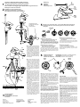
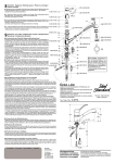
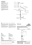
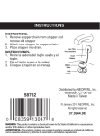
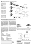
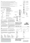
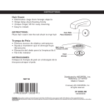
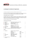
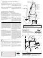
7
Ersatzteil - Regelung / Ordering spares / Pièces de rechange
Parti di ricambio
■ Bestellnummern für Ersatzteile siehe Zeichnung
auf dieser Seite. Bei Bestellung der Teile für XX die
Oberflächen-Kennung einsetzen (z.B: bei chrom statt
XX = AA einsetzen).
Oberflächen-Kennung siehe Ersatzteilbuch.
■
Les numéros de commande des pièces de
rechange sont indiqués dans le schéma. Pour
commander des pièces inscrire les suffixes
correspondants (par example: pour chrome indiquer
les suffixes AA au lieu de XX).
Les suffixes sont indiqués dans le catalogue des
piéces de rechange.
■ Spare part numbers are shown in diagram on this
page. When ordering parts add the appropriate suffix.
(for example: for chrome use AA instead of XX)
See Spare part catalogue for suffixes.
■ I codici di ordinazione dei ricambi sono riportati sul
disegno a lato. Per l'ordinazione di ricambi indicare il
relativo suffisso codice (per esempio: per cromato
indicare AA invece di XX). I suffissi codici sono riportati
nel catalogo ricambi.
A 960 807 XX
1
A 963 309 NU
2
A 963 820 XX 25
24
A 963 819 XX
3
A 963 054 NU
4
A 963 817 XX
5
A 963 176 NU
6
A 860 700 NU
7
A 960 500 NU
8
A 961 155 NU
9
8
10
Austausch von Teilen / Replacement of parts
Remplacement des pièces / Cambiamento dei pezzi
■ Auswechseln Metallschlauch
Handbrause 12 abschrauben. Gewicht 21 abnehmen.
Überwurfmutter 26 lösen und Schlauch nach oben
durch den Auslauf herausziehen. Den neuen
Schlauch in umgekehrter Reihenfolge montieren.
Gewicht wieder so befestigen, daß der Schlauch ca.
50 cm aus dem Auslauf herausziehbar ist.
13
14
■ Replacement du tuyau métallique
Dévisser la douche 12. Retirer le poids 21. Dévisser
l'écou-raccord 26 et tirer le tuyau vers le haut en le
faisant passer par la sortie. Remonter le nouveau
tuyau en procédant dans le sens inverse. Refixer le
poids de façon à pouvoir retirer le tuyau d'environ 50
cm de la sortie.
15
A 960 929 NU
A 963 361 NU 16
A 963 404 NU
■ Replacing the metal hose
Screw off spray attachement 12. Remove weight 21.
Screw off union nut 26 and pull out the hose upwards
through the outlet. Fit the new hose the reverse order.
Refasten the weight so as to allow the hose to be pulled
approx. 50 cm out of the outlet.
■ Sostituzione del tubo flessibile con guaina
metallica
Svitare la doccia a telefono 12 dal flessibile. Togliere
il peso 21. Svitare il dado a risvolto 26 e sfilare quindi
verso l'alto il tubo flessibile attraverso la bocca. Il
montaggio del nuovo tubo avviene eseguendo in
ordine inverso le stesse operazioni sopra descritte. Il
peso dovrà essere fissato sul nouvo tubo in modo da
permetterne l'estrazione dalla bocca per almeno 50
cm circa.
■ Auswechseln der Kartusche
Zulaufleitungen absperren. Stopfen 3 heraushebeln.
Schraube 2 lösen. Griff 1 nach oben abziehen. Kappe
4 abziehen. Stellring 6b wechselweise abhebeln (siehe Abschnitt 6 "Temperaturbegrenzer). Schrauben 5
lösen. Kartusche 7 mit Rasterring 6a abnehmen. Auflagefläche der Dichtringe 8 im Batteriekörper säubern.
Neue Kartusche mit Rasterring 6a einsetzen. Schrauben 5 wechselweise und nicht zu fest anziehen. Stellring 6b justieren und aufdrücken (Abschnitt 6). Teile 1
- 4 wieder montieren. Funktion und Dichtigkeit überprüfen.
■ Remplacement de la cartouche
Fermer les conduites d'arrivée. Faire ressortir le bouton
3 et desserrer la vis 2. Retirer le levier 1 en tirant vers
le haut. Retirer le capuchon 4. Soulever la bague
d'arrêt 6b à plusieurs endroits avec un tournevis (voir
description point 6 "Limitateur de température") et
dévisser les vis 5. Retirer la cartouche 7 avec l'bague
de blocage 6a. Nettoyer la surface d'appui des joints 8
à l'intérieur du corps du robinet mélangeur.
Placer une nouvelle cartouche avec l'bague de blocage
6a et serrer alternativement, pas trop fort, les vis 5.
Ajuster la bague d'arrêt 6b et l'enfoncer (voir description
point 6). Remonter les pièces 1 à 4 et vérifier le bon
fonctionnement et l'étanchéité.
■ Changing the cartridge
Shut off supply pipes. Lever out stopper 3 and undo
screw 2. Remove handle 1 by pulling upwards. Pull off
cap 4. Remove adjustment ring 6b by levering off from
alternate sides (see Chapter 6 "Temperatur Limiter").
Undo screws 5. Remove cartridge 7 with location ring
6a. Clean the surface on which sealing rings 8 rest in
the body of the mixer unit.
Fit new cartridge with location ring 6a. Tighten screws
5 alternately and not too tight. Position the adjustment
ring 6b and press it onto the unit (see Chapter 6). Refit
parts 1 - 4. Check that the unit functions correctly and
does not leak.
■ Cambio della cartuccia
Chiudere l'alimentazione dell'acqua. Togliere il coprivite
3. Svitare la vite 2. Sfilare la leva di comando 1
tirandola verso l'alto. Sfilare il cappuccio 4. Con l'aiuto
di un cacciavite a lama piatta fare leva alternativamente
ai due lati dell'anello di regolazione 6b per toglierlo
(vedi descrizione allegata "Limitatore di temperatura
acqua calda"). Svitare le tre viti 5 e togliere la cartuccia
6 insieme all'anello di bloccaggio 6a. Puliere la
superficie d'appoggio delle guarnizioni 8 nel corpo del
miscelatore. Inserire la nuova cartuccia con il anello di
bloccaggio 6a. Avvitare le viti 5 in alternanza senza
stringerle troppo. Girare l'anello di regolazione 6b
nella posizione desiderata e montarlo esercitando una
leggera pressione (vedi descrizione allegata "Limitatore
di temperatura acqua calda"). Rimontare quindi le
parti da 1 a 4. Verificare infine il regolare funzionamento
e la tenuta dei componenti.
9
23
22
26
Zur Reinigung der Armatur sollten nur seifenhaltige Reinigungsmittel verwendet werden. Keinesfalls
kratzende, scheuernde, alkohol-, ammoniak-,
salzsäure-, phosphorsäure- oder essigsäurehaltige
Reinigungs- oder Desinfektionsmittel benutzen.
When cleaning the fitting, only use saponaceous
( i. e. soap - based ) agents. Never use abrasive or
scouring powders, cleaning agents containing alcohol,
ammonia, nitric acid or phosphoric acid, or desinfectants.
12
A 963 818 XX
17
A 960 932 XX
18
A 961 230 XX
20
19 A 963 807 XX
Diese Armatur, ausgerüstet mit dem Rückflußverhinderer Pos.11*, der zwischen
Schlauch und Brause eingebaut wird, gilt als eigensicher, ist DVGW-geprüft und
zugelassen für Installationen mit Einzelabsicherung.
* wird bei einigen Armaturentypen mitgeliefert.
CERAMIX LIFT
Einhebel - Mischbatterie mit Handbrause
Single-lever mixer with pull out spray attachement
Robinet mélangeur à un levier pour évier avec douche
Miscelatore monocomando per lavelli con doccia a telefono
Typ / Type / Tipo:
TDA 1059 / 0205 / 965 750
Made in Germany
A 5014 ..
150
65
130
max. 28
■ Pour le nettoyage de la robinetterie, employer
seulement des produits contenant du savon. Jamais
de nettoyants ou des désinfectants qui grattent, rayent,
contiennent de l'alcool, de l' ammoniac, de l'acide
chlorhydrique ou phosphorique.
M 33 x 1,5
Ø63
350
■
A 962 594 NU
21
Pflege und Wartung / Maintenance / Entretien / Pulizia del miscelatore
■
11
max. 150
30 - 50
■ Per la pulizia del miscelatore si consiglia di usare
solamente detergenti a base di sapone. Non impiegare
in nessun caso detergenti o disinfettanti abrasivi o
contenenti alcool, ammoniaca, acido cloridrico o acido
fosforico.
G 1 1/4
Ihr Installateur / Your plumber / Votre installateur / L'installatore
Hersteller:
Ideal Standard
Pro-Service
Euskirchener Str. 80
53121 Bonn
Tel.: 0228-521580
Fax: 0228-521589
Montageanleitung
Installation instructions
instructions de montage
Istruzioni di montaggio
Bitte diese Anleitung an den Benutzer weitergeben!
Please hand these instructions to the user of the fitting!
S.v.p. remettre cette instruction á l'utilisateur de la
robinetterie!
Si prega di voler consegnare le presenti istruzioni
l'utilizzatore della rubinetteria!
1
Vor Beginn der Montage bitte sorgfältig durchlesen.
Please read carefully before commencing installation.
Lire attentivement avant de commencer le montage.
Prima di iniziare il montaggio leggere attentemente le seguenti istruzioni.
2
Montage nur durch den Fachmann.
Installation only by qualified expert.
Montage uniquement par un spécialiste.
Fare eseguire I lavori solo da un installatore.
4
Bedienung
Operation
Utilisation
Istruzioni per l'uso
zu
off
fermé
chiuso
auf
on
ouvert
aperta
kalt
cold
froid
fredda
warm
hot
chaud
calda
I
II
dauerplastischer Kitt
permanently elastic putty
joint silicone
mastice plastico
5
Dem Öko - Set ( siehe Plastic-Tüte ) ist eine grüne Wasserdrossel beigepackt.
Diese Wasserdrossel mit dieser Anleitung bitte an den Benutzer der Armatur
weitergeben.
963 361
III
V
IV
19
VII
■ Zulaufleitungen gut durchspülen,
um Schmutzreste zu entfernen. Nach
dem Biegen der Rohre darauf achten,
daß sich die Zugstange leicht bewegen läßt. Schlauch 19 von oben einführen und Handbrause 12 anschrauben. Schlauch anschrauben. Das
Gewicht 21 mittels der beigefügten
Schrauben 20 auf dem Metallschlauch
befestigen. Der Schlauch sollte danach ca. 50 cm aus dem Auslauf herausziehbar sein.Funktion und Dichtigkeit überprüfen.
12
■ Flush out supply pipes thoroughly
to remove traces of dirt. After bending
the pipes, ensure that the operating
rod still moves freely. Introduce hose
19 from above and onscrew the handspray 12. Onscrew the hose. Fasten
weight 21 to the metal hose with
enclosed screws 20. It should than be
possible to pull the hose approx. 50
cm out of the outlet. Check that all the
connections function correctly and are
leak-tight.
VIII
warm
hot
chaud
calda
VI
21
kalt
cold
froid
fredda
IX
20
max: 1 MPa (10 bar / 145 psi )
opt.: 0,1 MPa - 0,5 MPa (1 - 5 bar / 14,5 - 72,5 psi)
min: 0,1 MPa (1 bar / 14,5 psi)
> 0,5 MPa (5 bar / 72,5 psi) ➜
3
Technische Daten
Technical Data
Caractéristiques techniques
Dati tecnici
Prüfdruck:
Test pressure:
Pression d'essai:
Pressione di prova:
1,6 MPa (16 bar / 232 psi) max.
Betriebstemperatur:
Operating temperature:
Température de service:
Temperatura d'esercizio:
90 C max.
■ Bien rincer les conduites d´arrivée
d´eau, pour enlever les restes de
saleté. Après avoir courbé les tuyaux,
veiller à ce que la tirette se manoeuvre
facilement. Introduire le tuyau 19 par
le haut et visser la douche 12. Visser
le tuyau. Fixer le poids 21 sur le tuyau
métallique avec les vis 20 livrées avec
l'installation. Le tuyau devrait pouvoir
sortir ensulte de 50 cm environ de la
sortie orientable. Contrôler le fonctionnement et l'étanchéité de tous les
branchements.
■ Risciacquare accuratamente tutte
le condutture di alimentazione per
eliminare ogni residuo di sporco.Dopo
aver curvato i tubi di collegamento
fare attenzione che l´asta di comando
dello scarico possa venir azionata con
facilità.Inserire il tubo flessibile 17
dall'alto e avvitare la doccia a telefono
12. Avvitare il tubo flessibile. Fissare
il peso 21 sul flessibile stringendo le
viti 20 in una posizione tale da
permetterne l'estrazione per circa 50
cm. Controllare la funzione e la tenuta
ermetica di tutti i collegamenti.
Durchflußleistung:
Flow rate:
Débit:
Portate:
0,3 MPa (3 bar / 43,5 psi)
= 13 l/min
ca.10 l/min
3 bar
ca. 8 l/min
3 bar
ca. 7 l/min
3 bar
ca. 6 l/min
3 bar
■ Einbau der Wasserdrossel
Nicht geeignet für Durchlauferhitzer ( DE )
und offene Heißwasserbereiter ( ND ).
Luftsprudler von der Armatur abschrauben. Wasserdrossel wie im Bild dargestellt in den Luftsprudler
einsetzen. Gummiring über die Wasserdrossel legen
und den Luftsprudler wieder von Hand anschrauben.
■ Montage de l'économiseur d'eau
Ne peut pas être utilisé avec des chauffeeau instantanés.
Dévisser l'aérateur du robinet. Retirer le joint. Installer
l'économiseur d'eau sur l'aérateur. Reposer le joint sur
l'économiseur. Revisser l'ensemble.
■ Assembly of the flow restrictor
Not be used with instantaneous Water
Heaters and low pressure systems.
Unscrew the neoperl nozzle of the fitting. Insert the
flow restrictor into the neoperl nozzle as shown in the
picture. Put the rubber ring on top of the flow restrictor
and screw the neoperl nozzle by hand into the spout of
the fitting again.
■ Montaggio del riduttore
Non per riscaldabagno instantaneo.
Smontare il neoperl. Montare il riduttore come
disegnato. Montare la guarnizione di sopra e fissare il
neoperl a máno.
6
Temperatur-Begrenzer Temperature Limiter Limitateur de température -
JUSTIERUNG ( Vermeidung von Verbrühungsgefahr )
ADJUSTMENT ( protection against scalding )
AJUSTAGE ( Protection contre les brûlures )
A
Bild I
Fig. I
6b
Bild II
Fig. III
6a
■ Nachdem die Kartusche mit dem Rasterring festgeschraubt ist, Wasserzuführung öffnen. Griffhebel
aufstecken, Armatur öffnen und die gewünschte
Temperaturgrenze ansteuern. In dieser Position Kartusche schließen und Griffhebel abziehen. Den
Stellring 6b von oben so einsetzen, daß die Sperrnase
(A) in etwa mittig hinter der Griffhebelaufnahme einrastet (siehe Bild I, Markierung X). Dabei darauf achten,
daß die Zähne des Stellrings 6b in den Zahnkranz des
Rasterrings 6a greifen.
Kontrolle - den Griffhebel aufstecken, gegen den
Begrenzer drehen und Temperatur prüfen. Danach
Adapter, Kappe und Griffhebel wieder montieren.
NACHJUSTIERUNG
Muß der Stellring 6b neu positioniert werden, so ist
nach gleichem Schema zu verfahren. Griffhebel gegen den Begrenzer drehen, Kartusche schließen
und Griffhebel lösen u. abziehen. Mit einem Schraubendreher den Stellring 6b durch wechselseitiges Abhebeln entfernen (siehe Bild II). Neue Einstellung wie
unter Justierung beschrieben vornehmen.
■ After screwing tight the cartridge and locating ring,
turn on the water supply. Fit the lever-type handle, turn
on the mixer unit and move it to the desired temperature
limit. In this position turn off the mixer unit and
remove the handle. Fit the adjustment ring 6b from
above so that the limit stop lug (A) engages
approximately centrally behind the handle mount (see
the X in Fig. I). Ensure that the teeth of the adjustment
ring 6b grip in the teeth on the inside rim of the location
ring 6a. Check: fit the lever-type handle, turn it as far
as the limiter and check the temperature. Then refit
adapter, cap and handle.
READJUSTMENT
If adjustment ring 6b has to be repositioned, follow the
same procedure. Turn the handle as far as the limiter,
turn off the mixer unit and unscrew and pull off the
handle. Remove the adjustment ring 6b by levering up
from alternate sides using a screwdriver (see Fig. II).
Readjust the temperature limiter as described in the
section " ADJUSTMENT ".
■ Ouvrir l'arrivée d'eau après avoir assemblé et vissé
la cartouche et la bague de blocage. Mettre le levier en
place, l'ouvrir jusqu'à la température limite désirée.
Une fois arrivé dans cette position, fermer la cartouche
et retirer le levier. Mettre la baguet d'arrêt 6b de par
le haut en sorte que le tenon de blocage (A) s'enclenche
à peu près au centre, derrière le logement du levier
(voir Fig. I, repère X). Veiller à ce que les dents de la
bague d'arrêt 6b prennent dans la couronne dentée de
la bague de blocage 6a.
Contrôle. Mettre le levier en place, le tourner contre
le limitateur et vérifier la température. Remonter ensuite
l'adaptateur, le capuchon et le levier.
CORRECTION DU REGLAGE
S'il faut corriger la position de la bague d'arrêt 6b,
procéder de façon analogue. Tourner le levier contre
le limitateur, fermer la cartouche puis desserrer et
retirer le levier. Retirer la bague d'arrêt 6b à l'aide d'un
tournevis en la soulevant alternativement à plusieurs
endroits (voir Fig. II). Faire le nouveau réglage comme
décrit au paragraphe Ajustage.