1
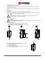
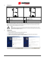
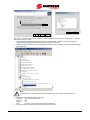
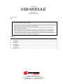
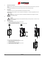
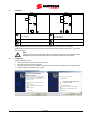
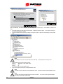
- 15G0078A130 - MODULO USB ISTRUZIONI INTERFACCIA PER ASAC-0/ASAC-1/ASAB Emesso il 15/06/2012 R. 01 Il presente manuale costituisce parte integrante ed essenziale del prodotto. Leggere attentamente le avvertenze contenute in esso in quanto forniscono importanti indicazioni riguardanti la sicurezza d'uso e di manutenzione. Questa macchina dovrà essere destinata al solo uso per il quale è stata espressamente concepita. Ogni altro uso è da considerarsi improprio e quindi pericoloso. Il Costruttore non può essere considerato responsabile per eventuali danni causati da usi impropri, erronei ed irragionevoli. L'Elettronica Santerno si ritiene responsabile della macchina nella sua configurazione originale. Qualsiasi intervento che alteri la struttura o il ciclo di funzionamento della macchina deve essere eseguito od autorizzato dall'Ufficio Tecnico della Elettronica Santerno. L'Elettronica Santerno non si ritiene responsabile delle conseguenze derivate dall'utilizzo di ricambi non originali. L'Elettronica Santerno si riserva di apportare eventuali modifiche tecniche sul presente manuale e sulla macchina senza obbligo di preavviso. Qualora vengano rilevati errori tipografici o di altro genere, le correzioni saranno incluse nelle nuove versioni del manuale. Proprietà riservata – Riproduzione vietata. L'Elettronica Santerno tutela i propri diritti sui disegni e sui cataloghi a termine di legge. Sommario 1 Informazioni importanti per l'utente ......................................................................................................................... 2 2 Introduzione ................................................................................................................................................................ 2 3 Installazione ................................................................................................................................................................ 2 4 Collegamento.............................................................................................................................................................. 3 5 Configurazione ........................................................................................................................................................... 3 6 Specifiche ................................................................................................................................................................... 5 Elettronica Santerno S.p.A. S.S. Selice, 47 – 40026 Imola (BO) Italy Tel. +39 0542 489711 – Fax +39 0542 489722 www.santerno.com, [email protected] 1 Informazioni importanti per l'utente Osservare tutte le precauzioni di sicurezza necessarie quando si controlla in remoto l'avviatore statico. Avvertire il personale che la macchina può avviarsi senza preavviso. L'installatore ha la responsabilità di seguire tutte le istruzioni contenute in questo manuale e tutte le pratiche appropriate per i sistemi elettrici. 2 Introduzione Il Modulo USB può essere utilizzato insieme a WinMaster per gestire gli avviatori statici Santerno. Queste istruzioni descrivono l'installazione, l'impostazione e la configurazione del Modulo USB. Per ottenere informazioni dettagliate sull'utilizzo di WinMaster, fare riferimento al file della Guida WinMaster. NOTA Affinché WinMaster possa comunicare con un avviatore statico tramite il modulo USB, WinMaster deve essere configurato in modo da usare i protocolli AP ASCII o AP Binary. 3 Installazione ATTENZIONE Togliere dall'avviatore statico la tensione di rete e la tensione di controllo prima di collegare o rimuovere accessori. In caso contrario si potrebbe danneggiare l'apparecchiatura. 3.1 Modalità d'installazione 1. 2. 3. Estrarre completamente la molletta di ritegno superiore e inferiore sul modulo. Allineare il modulo alla presa della porta di comunicazione. Infilare la molletta di ritegno superiore e inferiore per fissare il modulo all'avviatore. 2 3 1 0 1 7 8 .B 1 0 3 5 5 0 .B Rimuovere il modulo utilizzando la seguente procedura: 1. Togliere l'alimentazione al controllo e la tensione di rete all'avviatore statico. 2. Tenere il modulo fuori linea. 3. Scollegare il cavo USB dal modulo. 4. Estrarre completamente la molletta di ritegno superiore e inferiore sul modulo. 5. Estrarre il modulo dall'avviatore statico. 2/6 Modulo USB Collegamento ASAC 0 8 5 8 5 .B 1 4 ASAB 1 1 2 2 2 3 1 2 3 3 4 ASAC ASAB (modalità Remota) A1, 02: Ingresso Arresto Modulo USB 56, 57: Ingresso Arresto 58, 57: Ingresso Ripristino Modulo USB Porta USB Porta USB 3 11 6 0 9 .B 4 ASAC: Affinché il Modulo USB possa accettare comandi seriali, è necessario collegare tra loro i terminali A1-02 sull'avviatore statico. ASAB: È necessario collegare gli ingressi tra i terminali di arresto e ripristino se l'avviatore statico viene fatto funzionare in modalità Remota. In modalità Locale, tali collegamenti non sono necessari. NOTA ASAB: il parametro Comunicazione remota seleziona se l'avviatore statico può accettare comandi di Avvio e Arresto dal master della rete seriale mentre si trova in modalità remota. Consultare la guida dell'utente dell'avviatore statico per ottenere informazioni dettagliate sul parametro. Configurazione Per mettere in linea il Modulo USB: 1. Togliere l'alimentazione al controllo e la tensione di rete all'avviatore statico. 2. Attaccare il modulo all'avviatore statico come mostrato in figura. 3. Collegare il modulo al PC tramite un cavo USB. Il PC rileverà il modulo e si aprirà l'Aggiornamento guidato hardware. 4. Installare nel modo seguente il driver USB per il funzionamento del modulo. È possibile scaricare il driver dal sito santerno.com. W e lc o m e t o t h e F o u n d N e w H a r d w a r e W iz a r d W i n d o w s w i ll s e a r c h f o r c u rr e n t a n d u p d a t e d s o ft w a r e b y T h i s w iz a rd h e lp s y o u in s t a ll s o ft w a r e fo r: lo o k in g o n y o u r c o m p u te r, o n t h e h a r d w a re in s t a lla t io n C D , o r o n th e W in d o w s U p d a t e W e b s i te ( w it h y o u r p e r m i s s i o n ) . FT232R USB UA RT R e a d o u r p riv a c y p o l ic y I f y o u r h a r d w a r e c a m e w it h a n in s t a ll a t i o n C D C a n W i n d o w s c o n n e c t to W in d o w s U p d a t e to s e a rc h fo r o r f l o p p y d is k , i n s e r t it n o w . s o ft w a r e ? Ye s , t h i s t im e o n ly W h a t d o y o u w a n t th e w iz a r d t o d o ? Ye s , n o w a n d e v e ry t im e I c o n n e c t a d e v ic e I n s ta l l t h e s o ft w a re a u t o m a ti c a l ly ( R e c o m m e n d e d ) N o , n o t t h is ti m e I n s ta l l f ro m a l is t o r s p e c i fic lo c a t io n ( A d v a n c e d ) C lic k N e x t t o c o n t in u e . C li c k N e x t t o c o n t in u e . 0 8 5 8 8 .A 5 Modulo USB 3/6 P le a s e c h o o s e y o u r s e a r c h a n d i n s t a l l a t i o n o p t io n s . S e le c t th e fo l d e r th a t c o n ta i n s d r iv e rs fo r y o u r h a r d w a re . S e a r c h fo r t h e b e s t d riv e r i n th e s e lo c a t io n s . U s e th e c h e c k b o x e s b e l o w to lim i t o r e x p a n d t h e d e fa u l t s e a r c h , w h ic h i n c l u d e s l o c a l M y D o c u m e n ts p a t h s a n d r e m o v a b l e m e d ia . T h e b e s t d r iv e r fo u n d w ill b e i n s ta l le d . M y C o m p ute r S e a r c h r e m o v a b l e m e d ia ( fl o p p y, C D - R O M . ..) M y N e tw o r k P la c e s U S B C o m m s D ri v e r s In c lu d e th i s lo c a t io n i n th e s e a rc h W in 9 8 _ M E B row se C :\ D o c u m e n ts a n d S e tt in g s \ u s e r \ D e s k to p \ U S B C o m m W in X P _ V is t a am d64 D o n ’t s e a rc h . I w il l c h o o s e t h e d riv e r t o in s t a l l. i3 8 6 th e d ri v e r y o u c h o o s e w il l b e t h e b e s t m a t c h fo r y o u r h a rd w a r e . To v ie w a n y s u b fo l d e r s , c l ic k a p l u s s ig n a b o v e . OK < B ack Next > C a n cel 0 8 5 8 9 .A C h o o s e th is o p ti o n t o s e l e c t t h e d e v ic e d r iv e r fr o m a lis t. W in d o w s d o e s n o t g u a ra n t e e th a t Cancel Fare clic su Ok, quindi Next. Il software viene installato. Se viene visualizzato un prompt, fare clic su Continue Anyway. Al termine dell'installazione, fare clic su Finish. 5. Viene visualizzata la richiesta di installare il software del driver della porta seriale. Ripetere la procedura del passaggio 4. Talvolta al termine dell'installazione del software del driver è necessario riavviare il PC. 6. Individuare l'assegnazione della porta seriale USB andando in Pannello di controllo > Sistema > Hardware > Gestione periferiche> Porte (COM & LTP). C o m p u te r D is k d r iv e s D is p la y a d a p t e r s D V D /C D -R O M d r iv e s F lo p p y d is k c o n t r o lle r s F lo p p y d is k d r iv e s H u m a n In t e r fa c e D e v ic e s I D E A TA /AT A P I c o n t ro lle rs I E E E 1 3 9 4 B u s h o s t c o n t ro lle r s Key bo ards M ic e a n d o t h e r p o in t in g d e v ic e s M o n ito r s N e t w o rk a d a p t e r s P o rt s (C O M & L P T ) C o m m u n ic a tio n s P o rt (C O M 1 ) E C P P r in te r P o rt (L P T 1 ) I n te l(R ) A c t iv e M a n a g e m e n t Te c h n o lo g y - S O L (C O 0 8 5 9 0 .A U S B S e r ia l P o rt (C O M 5 ) P r o c e s s o rs NOTA Se la porta USB non è visualizzata, scollegare e poi ricollegare il cavo. Se il problema persiste, riavviare il PC. 7. 8. 4/6 Aprire WinMaster e modificare i parametri come segue: Protocollo: ASAC = ASCII; ASAB = Binario Baud rate: 9600 Indirizzo: 20 Porta: Utilizzare il numero di porta seriale individuato in precedenza Applicare la tensione di controllo all'avviatore statico e mettere in linea il master. Modulo USB NOTA L'avviatore potrebbe andare in errore per Avv/comunicazioni quando il master è fuori linea. Ripristinare l'avviatore statico e mettere in linea il master. NOTA I driver configureranno la porta USB a cui è collegato il modulo. È necessario utilizzare la stessa porta USB fisica ogni volta che si collega il modulo al PC. 6 Specifiche Alloggiamento Dimensioni ......................................................................................................................................... 40 mm (L) x 166 mm (H) x 90 mm (P) Peso ..................................................................................................................................................................................................... 250 g Livello di protezione ............................................................................................................................................................................... IP20 Montaggio Mollette di fissaggio a molla in plastica (x 2) Collegamenti Avviatore statico ..................................................................................................................................................................... gruppo a 6 pin Rete .................................................................................................................................................................................................... USB-B Lunghezza massima del cavo ....................................................................................................................................... 3 metri (non fornito) Impostazioni Protocollo .................................................................................................................................................................. AP binario o AP ASCII Indirizzo ..................................................................................................................................................................................................... 20 Velocità dati (bps) .................................................................................................................................................................................. 9600 Modulo USB 5/6 6/6 Modulo USB - 15G0078B130 - USB MODULE INSTRUCTIONS FOR ASAC-0/ASAC-1/ASAB Issued on 15/06/12 R. 01 This manual is integrant and essential to the product. Carefully read the instructions contained herein as they provide important hints for use and maintenance safety. This device is to be used only for the purposes it has been designed to. Other uses should be considered improper and dangerous. The manufacturer is not responsible for possible damages caused by improper, erroneous and irrational uses. Elettronica Santerno is responsible for the device in its original setting. Any changes to the structure or operating cycle of the device must be performed or authorized by the Engineering Department of Elettronica Santerno. Elettronica Santerno assumes no responsibility for the consequences resulting by the use of non-original spareparts. Elettronica Santerno reserves the right to make any technical changes to this manual and to the device without prior notice. If printing errors or similar are detected, the corrections will be included in the new releases of the manual. The information contained herein is the property of Elettronica Santerno and cannot be reproduced. Elettronica Santerno enforces its rights on the drawings and catalogues according to the law. Contents 1. Important User Information ...................................................................................................................................... 2 2. Introduction ................................................................................................................................................................ 2 3. Installation .................................................................................................................................................................. 2 4. Connection ................................................................................................................................................................. 3 5. Configuration ............................................................................................................................................................. 3 6. Specifications ............................................................................................................................................................ 5 Elettronica Santerno S.p.A. S.S. Selice, 47 – 40026 Imola (BO) Italy Tel. +39 0542 489711 – Fax +39 0542 489722 www.santerno.com, [email protected] 1. Important User Information Observe all necessary safety precautions when controlling the soft starter remotely. Alert personnel that machinery may start without warning. It is the installer's responsibility to follow all instructions in this manual and to follow correct electrical practice. 2. Introduction The USB Module can be used in conjunction with WinMaster to manage Santerno soft starters. These instructions detail the installation, set-up and configuration of the USB Module. For details on using WinMaster, refer to the WinMaster help file. NOTE For WinMaster to communicate with a soft starter via the USB Module, WinMaster must be configured to use the AP ASCII or AP Binary protocols. 3. Installation CAUTION Remove mains and control voltage from the soft starter before attaching or removing accessories. Failure to do so may damage the equipment. 3.1 Physical installation 1. 2. 3. Fully pull out the top and bottom retaining clips on the module. Line up the module with the comms port slot. Push in the top and bottom retaining clips to secure the module to the starter. 2 3 10178.B 1 Remove the module using the following procedure: 1. Remove control power and mains supply from the soft starter. 2. Take the module off-line. 3. Disconnect the USB cable from the module. 4. Fully pull out the top and bottom retaining clips on the module. 5. Pull the module away from the soft starter. 2/6 USB Module 4. Connection ASAB 1 1 2 2 11609.B 08585.B ASAC 3 3 ASAC ASAB (Remote mode) A1, 02: Stop input USB Module 56, 57: Stop input 58, 57: Reset input USB Module USB port USB port ASAC: For the USB Module to accept serial commands, a link must be fitted across terminals A1-02 on the soft starter. ASAB: Input links are required across the stop and reset inputs if the soft starter is being operated in Remote mode. In Local mode, links are not required. NOTE ASAB: Parameter Comms in Remote selects whether the soft starter will accept Start and Stop commands from the Serial Network Master while in Remote Mode. Refer to the soft starter user manual for parameter details. Configuration To bring the USB Module on-line: 1. Remove control power and mains supply from the soft starter. 2. Attach the module to the soft starter as illustrated. 3. Connect the module to the PC via a USB cable. The PC should detect the module and the Hardware Update Wizard will open. 4. Install the USB driver to operate the module as follows. The driver can be downloaded from santerno.com. Welcome to the Found New Hardware Wizard Windows will search for current and updated software by looking on your computer, on the hardware installation CD, or on the Windows Update Web site (with your permission). Read our privacy policy Can Windows connect to Windows Update to search for software? This wizard helps you install software for: FT232R USB UART If your hardware came with an installation CD or floppy disk, insert it now. Yes, this time only What do you want the wizard to do? Yes, now and every time I connect a device Install the software automatically (Recommended) No, not this time Install from a list or specific location (Advanced) Click Next to continue. Click Next to continue. USB Module 08588.A 5. 3/6 Please choose your search and installation options. Select the folder that contains drivers for your hardware. Search for the best driver in these locations. Search removable media (floppy, CD-ROM...) Include this location in the search Browse C:\Documents and Settings\user\Desktop\USB Comm Don’t search. I will choose the driver to install. Choose this option to select the device driver from a list. Windows does not guarantee that the driver you choose will be the best match for your hardware. My Documents My Computer My Network Places USB Comms Drivers Win98_ME WinXP_Vista amd64 i386 To view any subfolders, click a plus sign above. OK < Back Next > Cancel Cancel Computer Disk drives Display adapters DVD/CD-ROM drives Floppy disk controllers Floppy disk drives Human Interface Devices IDE ATA/ATAPI controllers IEEE 1394 Bus host controllers Keyboards Mice and other pointing devices Monitors Network adapters Ports (COM & LPT) Communications Port (COM1) ECP Printer Port (LPT1) Intel(R) Active Management Technology - SOL (CO USB Serial Port (COM5) Processors 08590.A Click on Ok, then Next. The software will install. If you see a prompt, click Continue Anyway. Once installation is complete, click Finish. 5. The PC will prompt you to install serial port driver software. Repeat the procedure in Step 4. You may need to restart your PC once the driver software is installed. 6. Identify the USB Serial Port assignment by checking Control panel > System > Hardware > Device Manager > Ports (COM & LPT). NOTE If the USB port is not shown, disconnect then reconnect the cable. If the problem persists, restart your PC. 7. 8. Open WinMaster and change the settings as follows: Protocol: ASAC Series = ASCII; ASAB = Binary Baud rate: 9600 Address: 20 Port: Use the serial port number identified above Apply control voltage to the soft starter and bring the Master on-line. NOTE The starter may trip on Starter Comms while the Master is off-line. Reset the soft starter and place the Master on-line. NOTE The drivers will configure the USB port that the module is connected to. You must use the same physical USB port every time you connect the module to the PC. 4/6 USB Module 08589.A Use the check boxes below to limit or expand the default search, which includes local paths and removable media. The best driver found will be installed. 6. Specifications Enclosure Dimensions ............................................................................................................................ 40 mm (W) x 166 mm (H) x 90 mm (D) Weight ........................................................................................................................................................................................ 250 g Protection ..................................................................................................................................................................................... IP20 Mounting Spring-action plastic mounting clips (x 2) Connections Soft starter ........................................................................................................................................................... 6-way pin assembly Network .................................................................................................................................................................................... USB-B Maximum cable length ................................................................................................................................... 3 metres (not supplied) Settings Protocol .......................................................................................................................................................... AP Binary or AP ASCII Address ........................................................................................................................................................................................... 20 Data rate (bps) ............................................................................................................................................................................ 9600 USB Module 5/6 710-11521-00B 6/6 USB Module