1
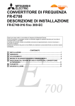
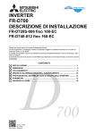
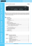
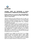
SOUND SYSTEM SPECIALIST
α
DATASHEET
AWF120-HV
AWF240-HV
Amplificatori con isolamento a 4 KV
Amplifiers with 4 KV insulation
β
INDICE DEI CONTENUTI
TABLE OF CONTENTS
1.
Descrizione generale .............................................. 3
1.1 Riferimenti numerati ........................................... 3
1.
General description ................................................ 3
1.1 Numbered references .......................................... 3
2.
Avvertenze .............................................................. 4
2.1 Informazioni generali .......................................... 4
2.2 Alimentazione e messa a terra ............................. 4
2.3 Note di sicurezza................................................. 4
2.
Warnings................................................................. 4
2.1 General information ............................................ 4
2.2 Power supply and earthing .................................. 4
2.3 Safety notes ....................................................... 4
3.
Esempio d’installazione ......................................... 5
3.
Example of installation .......................................... 5
4.
Connessioni ............................................................ 5
4.1 Criteri generali .................................................... 5
4.2 Ingresso/uscita di linea........................................ 5
4.3 Uscite di potenza ............................................... 6
• Sistemi a tensione costante ............................... 6
4.4 Accessori interni.................................................. 6
4.5 Scheda di controllo.............................................. 7
4.5.1 Connessioni .............................................. 7
• Collegamento alla linea altoparlanti ................... 7
• Collegamento ingressi (opzionale)...................... 7
• Collegamento del relè ....................................... 7
• Funzionamento del relè test .............................. 8
• Impostazione della modalità di
funzionamento del relè test .............................. 8
• Collegamento a potenziometro remoto ............... 8
• Connettore ‘REMOTE CONTROL’ ........................ 8
4.5.2 Modalità di funzionamento ......................... 8
A) Modalità ‘STAND ALONE’ ................................. 9
B) Modalità ‘REMOTE CONTROL’ ........................ 13
4.5.3 Calibrazione............................................. 13
4.
Connections ............................................................ 5
4.1 General criteria ................................................... 5
4.2 Line input/output ................................................ 5
4.3 Power outputs ................................................... 6
• Constant-voltage systems ................................. 6
4.4 Internal accessories ............................................ 6
4.5 Control card ....................................................... 7
4.5.1 Connections .............................................. 7
• Connecting to the loudspeakers line................... 7
• Connecting the inputs (optional) ........................ 7
• Connecting the relay ......................................... 7
• Operation of the test relay ................................ 8
• Setting the test relay
operation mode ................................................ 8
• Connection to the remote potentiometer ............ 8
• ‘REMOTE CONTROL’ Connector ......................... 8
4.5.2 Operating modes ....................................... 8
A) ‘STAND ALONE’ Mode ..................................... 9
B) ‘REMOTE CONTROL’ Mode ............................. 13
4.5.3 Calibration............................................... 13
5.
Uso dell’apparecchio ............................................ 14
5.1 Accensione ....................................................... 14
5.2 Display a led ..................................................... 14
5.
Using the equipment ............................................ 14
5.1 Switching on ..................................................... 14
5.2 LED Display ...................................................... 14
6.
Note di servizio..................................................... 14
6.1 Ventilazione forzata ........................................... 14
6.2 Condizioni di sovraccarico e protezione ............... 14
6.3 Tarature ........................................................... 14
6.
Service notes ........................................................ 14
6.1 Forced ventilation ............................................. 14
6.2 Overload conditions and protection devices......... 14
6.3 Adjustments ..................................................... 14
Caratteristiche tecniche ............................................... 15
Technical specifications ............................................... 15
Criteri di dimensionamento ......................................... 16
Dimensioning criteria ................................................... 16
Tavole di configurazione .............................................. 17
Configuration tables ..................................................... 17
Istruzioni per l’uso • Instructions for use
α
DATASHEET
Nel ringraziarVi per aver scelto un prodotto PASO, vogliamo ricordarVi
che la nostra azienda opera con sistema di qualità certificato. Tutti i
nostri prodotti vengono pertanto controllati in ogni fase della produzione
per garantirVi la piena soddisfazione del Vostro acquisto. Per ogni
evenienza la garanzia coprirà, nel periodo di validità, eventuali difetti
di fabbricazione. Vi raccomandiamo di leggere attentamente le seguenti
istruzioni d’uso per sfruttare appieno le prestazioni offerte da questo
prodotto e per evitare eventuali problemi.
While thanking you for having chosen a PASO product, we would like
to remind you that our company works according to a certified Quality
System. This means that all our products are checked during every phase
of manufacturing in order to ensure that you will be fully satisfied with your
purchase. In any case, the guarantee will cover any manufacturing flaws
during the guarantee period. We recommend that you read the following
instructions for use and follow them carefully in order to exploit in full the
performance of this product and use it correctly.
GARANZIA
Questo prodotto è garantito esente da difetti nelle sue materie prime e
nel suo montaggio; il periodo di garanzia è regolamentato dalle norme
vigenti. La Paso riparerà gratuitamente il prodotto difettoso qui garantito se
il difetto risulterà essersi verificato durante l’uso normale; la garanzia non
si estende quindi a prodotti usati ed installati in modo errato, danneggiati
meccanicamente, danneggiati da liquidi o da agenti atmosferici. Il prodotto,
risultato difettoso, dovrà essere inviato alla Paso franco di spese di
spedizione e ritorno. Questa garanzia non ne comprende altre, esplicite
od implicite, e non comprende danni o incidenti conseguenti a persone o
cose. Contattare i distributori PASO della zona per maggiori informazioni
sulla garanzia.
WARRANTY
This product is warranted to be free from defects in raw materials and
assembly. The warranty period is governed by the applicable provisions of
law. Paso will repair the product covered by this warranty free of charge
if it is faulty, provided the defect has occurred during normal use. The
warranty does not cover products that are improperly used or installed,
mechanically damaged or damaged by liquids or the weather. If the product
is found to be faulty, it must be sent to Paso free of charges for shipment
and return. This warranty does not include any others, either explicit or
implicit, and does not cover consequential damage to property or personal
injury. For further information concerning the warranty contact your local
PASO distributor.
Importante! L’utente ha la responsabilità di produrre una prova d’acquisto
(fattura o ricevuta) se vuole servirsi dell’assistenza coperta da garanzia.
Dovrà inoltre fornire data di acquisto, modello e numero di serie riportati
sull’apparecchio; a questo scopo, compilare come promemoria dei dati richiesti
lo spazio qui sotto.
Important! Should the user wish to avail himself of servicing under the
warranty, he must provide evidence of the purchase (invoice or receipt). The
user shall also indicate the date of purchase, model and serial number indicated
on the equipment. For this reason, you should complete the box below as a
reminder of the data required.
MODELLO / MODEL: .............................................................................................................................................................................................
NUMERO DI SERIE / SERIAL NUMBER: ..................................................................................................................................................................
DATA D’ACQUISTO / PURCHASE DATE: .................................................................................................................................................................
Questo prodotto è conforme alle Direttive della Comunità
Europea sotto le quali lo stesso ricade.
Tutti gli apparecchi PASO sono costruiti nel rispetto delle più severe normative
internazionali di sicurezza ed in ottemperanza ai requisiti della Comunità
Europea. Per un corretto ed efficace uso dell’apparecchio è importante prendere
conoscenza di tutte le caratteristiche leggendo attentamente le presenti
istruzioni ed in particolare le note di sicurezza.
2
This product is in keeping with the relevant European
Community Directives.
All PASO equipment is manufactured in accordance with the most stringent
international safety standards and in compliance with European Community
requisites. In order to use the equipment correctly and effectively, it is
important to be aware of all its characteristics by reading these instructions
and in particular the safety notes carefully.
TEEHSATAD
AWF120-HV, AWF240-HV
1.
DESCRIZIONE GENERALE
La peculiarità di questi amplificatori consiste nella
capacità di sopportare la presenza di elevate tensioni
tra alimentazione di rete/uscite altoparlanti e telaio, che
possono arrivare fino ai 4 kV.
Questa caratteristica aumenta la sicurezza dell’impianto,
impedendo che un’eventuale scarica sulla rete o sulle
connessioni altoparlanti possa risalire la catena audio e
provocare quindi gravi danni a cose o persone.
1.1
(1)
(2)
(3)
(4)
(5)
(6)
(7)
(8)
(9)
(10)
(11)
(12)
(13)
(14)
Riferimenti numerati
Spina di rete con fusibile incorporato.
Feritoie d’aerazione superiori.
Interruttore di rete.
Morsettiera diffusori ed alimentazione esterna in c.c.
Morsettiera Control I/O.
Dip-switch.
Regolatore volume d’uscita.
Led di conferma acquisizione impostazioni.
Spia di accensione.
Display a led.
Connettore per controllo remoto.
Prese per ingresso/uscita di linea.
Fusibile di protezione dell’alimentazione in c.c.
Feritoie d’aerazione inferiori.
Nota
Prima di usare l’apparecchio, leggere attentamente
le istruzioni contenute nel manuale cartaceo o su
supporto cd, ponendo particolare attenzione alle note
di sicurezza.
•••
1.
GENERAL DESCRIPTION
The peculiarity of these amplifiers consists of their
ability to withstand the presence of high voltages, up
to 4 kV, between the mains power/loudspeaker outputs
and the frames.
This feature increases the safety of the system as it
prevents discharges on the line or on the loudspeaker
line from moving up the audio chain and causing serious
damage to property or personal harm.
1.1
(1)
(2)
(3)
(4)
(5)
(6)
(7)
(8)
(9)
(10)
(11)
(12)
(13)
(14)
Numbered references
Mains plug with built-in fuse.
Upper ventilation slits.
Mains power switch.
Terminal strip for loudspeakers and external
power supply.
Control I/O terminal strip.
Dip-switch.
Output volume controller.
LED for acquisition settings confirmation.
ON/OFF signalling lamp.
LED display.
Remote control connector.
Line input/output sockets.
Fuse for protecting the DC power supply.
Lower ventilation slits.
Note
Before using the equipment, make yourself aware of
all characteristics by reading carefully the instructions
included in the printed manual or on the CD, paying
particular attention to the safety notes.
3
α
4
DATASHEET
2.
AVVERTENZE
2.1 Informazioni generali
Tutti gli apparecchi PASO sono costruiti nel rispetto delle più severe
normative internazionali di sicurezza ed in ottemperanza ai requisiti della
Comunità Europea. Per un corretto ed efficace uso dell’apparecchio
è importante prendere conoscenza di tutte le caratteristiche
leggendo attentamente le presenti istruzioni ed in particolare le
note di sicurezza. Durante il funzionamento dell’apparecchio è necessario
assicurare un’adeguata ventilazione. Evitare di racchiudere l’apparecchio in
un mobile privo di aerazione o di ostruirne le fessure di ventilazione. Evitare
inoltre di tenere l’apparecchio in prossimità di sorgenti di calore (termosifoni,
impianti di riscaldamento, ecc.). Prima dell’accensione assicurarsi che tutti
gli ingressi e le uscite siano correttamente collegati.
2.
WARNINGS
2.1 General information
All PASO equipment is built according to the strictest international safety
standards and complies with European Community requisites. In order
to use the equipment correctly and effectively, it is important
to be aware of all its features by reading these instructions and
in particular the notes on safety carefully. While the equipment is
working, it is necessary to ensure adequate ventilation. Avoid closing the
equipment inside a cabinet without ventilation and take care not to obstruct
the ventilation slits. Also avoid keeping the equipment near a source of
heat (radiator, heating systems and so on).
Before switching on the equipment, make sure that all the inputs and
outputs are correctly connected.
2.2 Alimentazione e messa a terra
L’apparecchio è predisposto per il funzionamento con tensione di rete a
230 V ± 10% 50/60 Hz. E’ prevista, in alternativa, la possibilità di alimentare
l’apparecchio con una tensione continua esterna di 24V da applicare agli
appositi morsetti ‘24V’ della morsettiera (4). I terminali della morsettiera
accettano cavi con una sezione massima di 2,5 mm2; si tenga presente che,
per brevi tratti (non superiori ai due metri), la sezione minima dei cavi di
collegamento deve essere di 1,5 mm2. Tipicamente questa tensione proviene
da accumulatori mantenuti sotto carica in tampone ed entra in funzione
soltanto in caso di emergenza; è necessario, in questo caso, prevedere
l’uso di un relè esterno che connetta le batterie all’apparecchio solo quando
viene a mancare l’alimentazione di rete. L’apparecchio è protetto contro le
inversioni di polarità. In accordo con le normative di sicurezza, l’interruttore
di accensione (3) agisce solo sulla tensione di rete.
2.2 Power supply and earthing
The equipment has provisions for operation with a mains voltage of 230 V
± 10% 50/60 Hz. As an alternative, it is possible to power the equipment
with an external continuous voltage of 24V to be applied to the appropriate
‘24V’ terminal on the terminal strip (4). The terminals on the terminal strip
take cables with a maximum cross-section of 2.5 mm2. Note, however, that
for short stretches (not exceeding two metres), the cross-section of the
connecting cables must be at least 1.5 mm2. Typically, this voltage is taken
from accumulators under float charged that only starts working in case of
emergencies. In this case, it is necessary to envisage use of an external
relay for connecting the batteries to the equipment only when the mains
power supply fails. The equipment is protected against polarity inversions.
In accordance with the safety regulations, the ON/OFF switch (4) is only
effective for the mains power supply.
2.3 Note di sicurezza
Ogni intervento all’interno dell’apparecchio, quale la selezione di alcuni modi
d’uso o l’applicazione di accessori, deve essere effettuato solo da personale
specializzato: la rimozione del coperchio rende accessibili parti con
rischio di scosse elettriche. Prima di rimuovere i pannelli di chiusura,
accertarsi sempre che il cavo di rete sia staccato. Nel caso di accidentale
caduta di liquidi sull’apparecchio, staccare immediatamente la spina di
rete ed interpellare il centro di assistenza PASO più vicino. L’apparecchio
é corredato di cavo di alimentazione con filo di terra ed il relativo terminale
sulla spina di rete non deve essere rimosso in alcun caso. Assicurarsi
che la presa di corrente sia dotata di collegamento di terra a norma di
legge. La connessione di massa telaio
della morsettiera (4) consente
di collegare altre apparecchiature per la sola funzione di schermatura dei
segnali a basso livello: questa presa non deve essere utilizzata per
il collegamento di sicurezza del telaio alla terra.
2.3 Safety notes
Any work inside the equipment, such as selecting some of the modes of
operation or applying accessories may only be carried out by specialised
personnel. On removing the cover, parts entailing a danger of
electric shocks will be made accessible. Always make sure that the
mains cable of the power-supply module is disconnected before removing
the panels. If any liquid is accidentally spilt on the equipment, disconnect
the mains cable immediately and contact the nearest PASO Service Centre.
The equipment is supplied with its own power-supply cable with an earth
wire. The relevant terminal on the mains plug must never be removed,
under any circumstances. Make sure that the power outlet has a connection
to earth in accordance with the law. The frame ground connection
(4)
can be used to connect other equipment for the sole purpose of shielding
low-level signals. This socket must never be used for the safety
connection of the frame to earth.
IMPORTANTE!
IMPORTANT!
sono attivi e pericolosi.
I terminali marcati con il simbolo
Il cablaggio esterno collegato a questi terminali, DEVE essere
eseguito esclusivamente da personale specializzato.
are active and
The terminals marked with the symbol
dangerous. The external connections toward these terminals
MUST be carried out by specialized personnel only.
Nota
PASO S.p.A declina ogni responsabilità per danni a cose e/o persone
derivanti dall’uso non corretto dell’apparecchio o da procedure non
rispondenti a quanto riportato sul presente libretto. Nel continuo intento di
migliorare i propri prodotti, la PASO S.p.A. si riserva il diritto di apportare
modifiche ai disegni e alle caratteristiche tecniche in qualsiasi momento
e senza alcun preavviso.
Note
PASO S.p.A will not accept any liability for damage to property and/or
persons arising out of incorrect use of the equipment or of procedures
that do not comply with the instructions provided in this booklet. PASO
S.p.A. strive to improve their products continuously, and therefore reserve
the right to make changes to the drawings and technical specifications at
any time and without notice.
TEEHSATAD
3.
ESEMPIO D’INSTALLAZIONE
L’amplificatore può essere montato e fissato a parete in maniera molto
semplice utilizzando l’apposita piastra fornita in dotazione. Per procedere
con il fissaggio, operare come segue:
1. Utilizzare la piastra (A) come dima e prendere nota della posizione dei
fori (B);
2. Forare la parete e posizionare la piastra fissandola con fischer, viti e
rondelle - non inclusi - a seconda delle specifiche esigenze;
3. Inserire l’amplificatore sulla piastra facendo coincidere i perni (C) con
le asole presenti sul pannello posteriore e farlo scorrere verso il basso;
fissare quindi l’amplificatore alla piastra tramite il galletto (D).
AWF120-HV, AWF240-HV
3.
EXAMPLE OF INSTALLATION
The amplifier can be mounted and fixed to the wall in a very simple using
the supplied plate.
To proceed with the mounting, follow these steps:
1. Use the plate (A) as template, and note the position of the holes
(B);
2. Pierce the wall and place the plate securing it by fishers, screws and
washers - not included - depending on your specific needs;
3. Insert the amplifier on the plate by the pins (C) with the slots on the
rear panel and slide down, then set the amp to the plate through the
wing nut (D).
B
C
A
Fig. 3.1.1
Fig. 3.1.2
Fig. 3.1.3
4.
CONNESSIONI
4.1 Criteri generali
Per un corretto funzionamento dell’apparecchio è opportuno osservare
alcuni criteri di massima nell’esecuzione dei collegamenti:
• evitare il posizionamento di cavi e di microfoni sul mobile
dell’apparecchio.
• evitare di stendere le linee di segnale parallele a quelle di rete;
osservare una distanza minima di 30/40 cm.
• posizionare le linee di ingresso e le linee di uscita distanti tra loro.
• posizionare i microfoni al di fuori dell’angolo di radiazione dei diffusori
sonori per evitare il fenomeno di reazione acustica (effetto Larsen).
4.
CONNECTIONS
4.1 General criteria
In order to allow the equipment to work correctly, it is advisable to comply
with a number of general criteria when making the connections:
• Avoid positioning cables or microphones on the cabinet of the
equipment.
• Avoid laying the signal lines parallel to the power-supply lines. Keep a
minimum distance of 30/40 cm.
• Position the input and the output lines at a distance from one another.
• In order to avoid acoustic feedback (the Larsen effect), position the
microphones out of the angle of coverage of the loudspeakers.
4.2 Ingresso/uscita di linea
Sul pannello frontale dell’apparecchio sono disponibili le prese XLR
d’ingresso/uscita (12) per segnali a livello linea (0 dB, 775 mV) dell’unità
di potenza; le prese sono parallelate per agevolare il collegamento in
cascata di più unità di potenza. In fig. 4.2.1 sono riportate le connessioni
a queste prese. L’ingresso dell’amplificatore è bilanciato elettronicamente;
per particolari esigenze come, ad esempio, nel caso di lunghi cavi di
collegamento e/o forti campi elettromagnetici disturbanti, è possibile
isolare galvanicamente l’ingresso dell’amplificatore tramite la scheda
opzionale TM92, dotata di traslatore di linea (vedi paragrafo 4.4).
4.2 Line input/output
The XLR input/output sockets (12) for the line-level signals (0 dB, 775
mV) of the power unit are located on the front panel of the equipment. The
sockets are paralleled in order to facilitate cascade connection of several
power units. Figure 4.2.1 shows the connections to these sockets.
The input of the amplifier is electronically balanced. For special
requirements such as, for example, in case of long connecting cables
and/or strong electromagnetic fields that cause interference, it is possible
to insulate the amplifier input galvanically using the optional TM92 card,
equipped with a line transformer (see paragraph 4.4).
IN/OUT
IN/OUT
1 = Schermo - Shield
2 = Segnale (lato caldo) - Signal (warm side)
3 = Segnale (lato freddo) - Signal (cold side)
XLR-F
XLR-M
Fig. 4.2.1
5
α
DATASHEET
4.3 Uscite di potenza
Le uscite di potenza per i diffusori sono disponibili sulla morsettiera (4)
per impianti di distribuzione a tensione costante (50, 70 e 100 V) e per
connessioni a bassa impedenza (4/8 Ω). In tabella 4.3.1 sono riportati i
valori nominali di tensione ed impedenza per le diverse uscite.
4.3 Power outputs
The power outputs for the speaker units are available on the terminal
strip (4) for constant-voltage distribution systems (50, 70 and 100 V)
and for low-impedance connections (4/8 Ω). Table 4.3.1 shows voltage
and impedance rated values for the various outputs.
Uscita / Output
AWF120-HV
AWF240-HV
50 V
20,8 Ω
10,4 Ω
70 V
40,8 Ω
20,4 Ω
100 V
83,3 Ω
41,7 Ω
Tab. 4.3.1
• Sistemi a tensione costante
Nel caso di impianti con un gran numero di diffusori e/o con distanze
tra amplificatori ed altoparlanti molto elevate é preferibile utilizzare
un sistema di distribuzione a tensione costante (definito anche ad
alta impedenza). In questo tipo di impianto, i diffusori, provvisti di
trasformatori di adattamento d’impedenza, sono tutti collegati in
derivazione alla linea (vedi Fig. 4.3.2).
• Constant-voltage systems
For systems including a large number of loudspeakers and/or with large
distances between the amplifiers and the loudspeakers, it is preferable
to use a constant-voltage distribution system (also known as highimpedance systems). In this type of system the loudspeakers, which are
equipped with impedance-matching transformers, are all connected by
branching them from the line (see example in Figure 4.3.2).
Fig. 4.3.2
Questo particolare rende di facile realizzazione l’impianto e, nel caso in
cui un altoparlante dovesse per qualche motivo scollegarsi dalla linea,
il resto dell’impianto proseguirebbe nel suo regolare funzionamento. Le
tensioni costanti disponibili in uscita dall’amplificatore sono da 50, 70
e 100 V. Per il corretto dimensionamento dell’impianto (scelta della
tensione di linea dell’apparecchio e selezione della potenza del diffusore)
é possibile individuare diverse procedure, riportate con esempi numerici
nella sezione ‘Criteri di dimensionamento’ (pag. 16).
This fact makes the system easy to create and, if any of the loudspeakers
should be disconnected from the line for any reason, the rest of the
system would continue to function properly. The constant voltages
available as outputs from the amplifier are 50, 70 and 100 V. There are
several possible procedures for sizing the system correctly (by choosing
the line voltage of the equipment or by choosing the output power of
the loudspeaker). Numerical examples of these procedures are provided
at section ‘Dimensioning criteria’ (page 16).
4.4 Accessori interni
4.4 Internal accessories
Queste operazioni richiedono la rimozione del pannello laterale
destro e rendono pertanto accessibili parti con rischio di scosse
elettriche: devono essere quindi affidate SOLO a personale
tecnico qualificato.
These operations require the removal of the right side panel and
make it accessible parts with risk of electric shock: they must be
entrusted ONLY by qualified personnel.
Internamente all’amplificatore è possibile installare l’accessorio TM92
(scheda traslatore di linea). Una volta rimosso il pannello laterale destro
dell’amplificatore, identificare il connettore CN101 (fig. 4.4.1); rimuovere
i ponticelli cortocircuitanti in esso inseriti e posizionare al loro posto
la scheda TM92. Richiudere l’apparecchio riposizionando il pannello
precedentemente rimosso.
The accessory TM92 (line translator card) can be installed inside the
amplifier. Once removed the side panel, identify connector CN101 (fig.
4.4.1), remove the jumpers inserted into it and put in place the card
TM92. Replace the unit repositioning the panel previously removed.
Fig. 4.4.1
6
TEEHSATAD
AWF120-HV, AWF240-HV
4.5 Scheda di controllo
Gli amplificatori sono equipaggiati con la scheda di controllo PM2092/2-V,
in grado di offrire un’elevato numero di funzioni aggiuntive.
4.5 Control card
The amplifiers are equipped with PM2092/2-V control card, which is
able to provide a range of additional functions.
NOTA: per motivi di sicurezza, sulla scheda PM2092/2-V risulta
disattivato il controllo del test GROUND FAULT.
NOTE : for safety reasons, the check of the GROUND FAULT TEST
will be de-activated on the PM2092/2-V.
Questa gestisce tutte le funzioni dell’amplificatore, dagli ingressi alla
diagnostica ed è in grado di eseguire le seguenti funzioni:
• misure di impedenza di linea;
• diagnostica dell’amplificatore;
• verifica dell’integrità della linea altoparlanti (PM2094-V).
• verifica isolamento di terra (GND FAULT);
• controllo di volume;
• selezione di due ingressi;
• controllo relè segnalazione guasti;
• possibilità di inserimento del filtro LOW CUT;
• funzionamento in modalità di risparmio energetico ‘LOW POWER’.
La scheda può inoltre essere controllata tramite interfaccia seriale. Oltre ad
eseguire tutte le operazioni e/o verifiche impostate localmente con i dipswitches, sarà possibile visualizzare e modificare tutti i parametri tra cui:
• lettura dell’impedenza di riferimento per il test;
• valore minimo e massimo entro cui il test risulta valido;
• lettura dello stato dei test;
• test dell’ingresso;
• misura della temperatura dei transistor finali;
• regolazione del volume;
• comando remoto del relè test.
This card manages all the functions of the amplifier, from the inputs to
diagnostics, and is capable of carrying out the following functions:
• line impedance measurements;
• amplifier diagnostics;
• check of the integrity of the loudspeaker line (PM2094-V).
• check of insulation to earth (GND FAULT);
• volume control;
• selection of two inputs;
• checking of fault-reporting relay;
• possibility of including the LOW CUT filter;
• operation in the ‘LOW POWER’ energy-saving mode.
The card can also be controlled via a serial interface. In addition to carrying out
all the operations and/or checks set locally by means of the dip switches, it will
also be possible to display and alter all the parameters, including the following:
• reading of the reference impedance for the test;
• minimum and maximum values between which the test is valid;
• reading of the test status;
• testing of the input;
• measurement of the temperature of the end transistors;
• volume adjustment;
• remote control of test relay.
4.5.1 Connessioni
La morsettiera ‘CONTROL I/O’ (5) presente sul pannello frontale
dell’amplificatore permette di utilizzare, se necessario, il relè, il secondo
ingresso bilanciato ed un eventuale controllo remoto del volume.
• Collegamento alla linea altoparlanti
Il collegamento agli altoparlanti viene illustrato nella figura 4.5.1
4.5.1 Connections
The ‘CONTROL I/O’ terminal strip (5) on the front panel of the amplifier
can be used, if necessary, to active the relay, the second balanced input
and the volume control.
• Connecting the loudspeakers line
The connection to the loudspeakers line is shown in fig. 4.5.1.
Fig. 4.5.1
• Collegamento ingressi (opzionale)
Qualora si volesse collegare un secondo ingresso, utilizzare i terminali 8,
9 e 10 della morsettiera ‘CONTROL I/O’ (5) (vedi fig. 4.5.2).
• Connecting the inputs (optional)
If you wish to connect a second input, use terminals 8, 9 and 10 of the
‘CONTROL I/O’ terminal strip (5), as shown in Figure 4.5.2.
Fig. 4.5.2
Fig. 4.5.3
• Collegamento del relè
Come riportato sul pannello dell’amplificatore, i collegamenti del relè
sono quelli illustrati in fig. 4.5.3.
• Connecting the relay
As shown on the top panel of the amplifier, the connections for the relay
are those illustrated in Figure 4.5.3.
7
α
DATASHEET
• Funzionamento del relè test
Le modalità di funzionamento del relè test sono tre.
La prima (MODE 0 - impostazione di fabbrica) prevede che il relè test sia
sempre eccitato e si disecciti solo per mancanza di alimentazione o guasto
all’amplificatore. In questa modalità è possibile, tramite l’utilizzo della
scheda PM2095, impostare un sistema di più amplificatori con l’inserzione
automatica di una o più riserve.
La seconda modalità (MODE 1), il relè test è sempre eccitato e si diseccita
solo in presenza di un guasto sulla linea degli altoparlanti.
Nella terza modalità (MODE 2), il relè test è sempre eccitato e si diseccita
se vi è un guasto di linea o dell’amplificatore.
• Operation of the test relay
There are three operation modes of the test relay.
In the first mode (MODE 0 – factory setting), the test relay is always
energized and is de-energised only in the absence of power or in case of
failure of the amplifier. It this mode it is possible to use the PM2095 card
to set up a system of several amplifiers with automatic inclusion of one
or more standby units.
In the second mode (MODE 1), the test relay is always energized and is
de-energized only if there is a failure on the loudspeaker line.
In the third mode (MODE 2), the test relay is always energized and is
de-energized if there is a line or amplifier failure.
• Impostazione della modalità di funzionamento del relè test
Viene di seguito illustrata la sequenza da effettuare per impostare
le diverse modalità tramite il dip-switch della scheda. Le leve vanno
abbassate in modo sequenziale (non simultaneo).
• Setting the test relay operating mode
The sequence to be carried out to set the various modes by means of the
dip switch on the card is illustrated below. The levers must be lowered in
sequence (not simultaneously).
• Collegamento a potenziometro remoto
Il potenziometro per il controllo a distanza del volume deve essere
collegato ai terminali 6, 7 e 8 della morsettiera ‘CONTROL I/O’. Fare
riferimento alla fig. 4.5.5 per incrementare o decrementare il volume.
7
7
7
6
6
6
Guasto linea
Line failure
5
5
4
4
3
1 2
ON
3
1 2
ON
3
3
1 2
ON
3
1 2
ON
4
3
1 2
ON
4
3
1 2
ON
4
3
1 2
ON
4
3
1 2
ON
4
4
5
5
5
5
5
5
6
6
6
6
6
6
5
4
3
1 2
ON
Guasto amplificatore
Amplifier failure
D
7
7
7
7
7
7
7
6
5
4
3
1 2
ON
MODE 1
C
8
8
8
8
8
8
8
8
7
6
5
4
3
1 2
ON
MODE 0
B
8
A
8
D
1 2
ON
C
8
B
7
A
6
D
5
C
4
B
8
A
Fig. 4.5.4
MODE 2
Guasto amplificatore o linea
Amplifier or line failure
• Connection to the remote potentiometer
The potentiometer for remote volume control must be connected to
terminals 6, 7 and 8 of the ‘CONTROL I/O’ terminal strip. Refer to Figure
4.5.5 for raising or lowering the volume.
10 kΩ
Potenziometro lineare
Linear potentiometer
Fig. 4.5.5
• Connettore ‘REMOTE CONTROL’
Questo connettore deve essere utilizzato per il collegamento
dell’amplificatore ad un PC o ad un sistema PMS2000/PMS2006-VES.
Una volta effettuata questa connessione, sarà possibile controllare tramite
software dedicato la scheda PM2092/2-V. Nella tabella sottostante è
riportata la piedinatura del connettore.
REMOTE CONTROL
Pin
• ‘REMOTE CONTROL’ Connector
This connector must be used to connect the amplifier to a PC or to a
PMS2000/PMS2006-VES system. Once this connection has been
made, it will then be possible to control the PM2092/2-V card by
means of dedicated software. The following table shows the pinout of
the connector.
Descrizione
Description
1
Alimentazione esterna 24V (opzionale)
24V External power supply (optional)
2
Alimentazione esterna 24V (opzionale)
24V External power supply (optional)
3
Massa
GND
4
Selezione ingressi
Inputs selection
5
RS485 +
RS485 +
6
Alimentazione esterna 24V (opzionale)
24V External power supply (optional)
7
Massa
GND
8
Massa
GND
9
RS485 –
RS485 –
Tab. 4.5.6
4.5.2 Modalità di funzionamento
Le modalità di funzionamento consentite dalla scheda sono due:
• Modalità ‘Stand-alone’;
• Modalità ‘Controllo remoto’
Nei paragrafi seguenti verranno illustrate tutte le impostazioni e le modifiche
che possono essere applicate alla scheda in entrambe le modalità d’uso.
8
4.5.2 Operating modes
There are two possible operating modes enabled by the card:
• ‘Stand-alone’ Mode;
• ‘Remote control’ Mode
The settings and the changes that can be applied to the card in each of
the operating modes are described in the following paragraphs.
AWF120-HV, AWF240-HV
TEEHSATAD
A) Modalità ‘STAND ALONE’
In questa modalità, è necessario impostare alcuni parametri tramite l’apposito
dip-switch ‘MODE SEL.’ (6) presente sul posteriore dell’amplificatore.
La levetta 1 del dip-switch svolge la funzione di ‘Invio’: deve essere cioè
utilizzata per dare conferma delle scelte effettuate con le altre leve.
A) ‘STAND ALONE’ Mode
In this mode, it is necessary to set some parameters using the ‘MODE SEL.’
(6) dip-switch provided for this purpose on the rear of the amplifier.
Lever 1 of the dip-switch has an ‘Enter’ function. That is to say, it has to
be used to confirm the choices opted for with the other levers.
• Acquisizione dell’impedenza della linea altoparlanti
Una volta installate in modo definitivo le linee di altoparlanti e collegato
l’amplificatore come indicato nel capitolo ‘Connessioni’, è necessario che
l’amplificatore acquisisca l’impedenza corrente. Tale impedenza verrà
presa come riferimento per le misurazioni future.
• Loudspeakers line impedance acquisition
Once the loudspeakers lines has been permanently installed, and the
amplifier has been connected as indicated in the chapter on ‘Connections’,
it is necessary for the amplifier to acquire the current impedance. This
impedance value will be used as a reference for the future measurements.
If the results of the measurements exceed the
reference value by ±30%, the amplifier will
signal the problem that has been detected by
means of the LED. To acquire the reference
impedance value, proceed as follows:
8
8
8
6
5
4
3
1 2
ON
6
5
3
1 2
ON
4
3. Return levers 1 and 8 to the OFF position:
the red LED will extinguish.
Fig. 4.5.7
• Setting the interval between one test and the next
Levers 4 to 8 have to be used for setting the required testing interval.
Lever 2 identifies the ‘test time’ mode.
For example, to set an interval of 5 seconds:
1. Move lever 2 to the ON position;
2. Move lever 1 to the ON position (Enter): the red ‘OK’ LED will light up
steadily.
3. Return lever 1 and then lever 2 to the OFF position. The LED will
extinguish to show that the setting has been correctly acquired.
Figure 4.5.8 shows examples referred to setting the most commonly used
intervals.
0 = 5 sec. (intervallo minimo/minimum interval)
1 = 1 min
8
7
6
5
4
3
1 2
ON
8
7
6
5
4
3
1 2
ON
8
7
6
3
4
5
6
7
8
D
1 2
ON
8
7
6
5
4
3
1 2
ON
8
7
6
5
4
3
1 2
ON
3
1 2
ON
C
31 = NO TEST
5
6
7
8
D
3
3
3
3
3
3
3
1 2
ON
1 2
ON
1 2
ON
1 2
ON
1 2
ON
1 2
ON
4
5
6
7
8
C
4
5
6
7
8
B
4
5
6
7
8
A
4
5
6
7
8
D
4
8
7
6
5
B
1 2
ON
4
8
7
6
5
D
3
4
8
7
6
5
C
C
1 2
ON
4
B
5
8
7
6
5
4
3
8
7
6
5
3
1 2
ON
4
8
7
6
5
3
4
A
2 = 2 min
A
B
30 = 1 h (intervallo massimo/maximum interval)
D
1 2
ON
4
5
6
7
8
C
3
4
5
6
7
8
B
1 2
ON
1 2
ON
3
4
5
6
7
8
A
29 = 29 min
A
1 2
ON
3
4
5
6
7
8
D
1 2
ON
3
4
5
6
7
8
C
1 2
ON
3
4
5
6
7
8
B
1 2
ON
1 2
ON
3
4
5
6
7
8
A
4
• Impostazione dell’intervallo tra un test ed il successivo
Per impostare l’intervallo di test desiderato, devono essere utilizzate le
levette da 4 a 8. La levetta 2 identifica il modo ‘test time’. Impostiamo ad
esempio un intervallo di 5 secondi:
1. Portare la levetta 2 in posizione ON;
2. Portare in posizione ON la levetta 1 (Invio):
il led rosso ‘OK’ si accende in modo fisso.
3. Riportare in posizione OFF la leva 1 e successivamente la leva 2; il led si
spegne indicando che l’impostazione è stata acquisita correttamente.
Riportiamo nella figura 4.5.8 gli esempi della impostazione degli intervalli
più comuni.
3
6
5
3
1 2
ON
4
6
5
4
3
1 2
ON
3. Riportare la leva 1 e la leva 8 in posizione
OFF: il led rosso si spegne.
1. Switch on the amplifier.
2. Operate the dip switch by moving lever 8 to
the ON position and then lever 1 as shown
in Figure 4.5.7.
After about 2 seconds the red ‘OK’ LED
will remain steadily on to indicate correct
acquisition of the line impedance.
7
D
7
C
7
B
7
1. Accendere l’amplificatore.
2. Operare sul dip-switch portando in posizione
ON la levetta 8 e successivamente la levetta
1 come indicato in figura 4.5.7.
Il led rosso ‘OK’ dopo circa 2 secondi rimarrà
acceso in modo fisso ad indicare la corretta
acquisizione dell’impedenza di linea.
A
8
Acquisizione impedenza linea altoparlanti
Loudspeakers line impedance acquisition
1 2
ON
Qualora le misure superino il ±30% della
misura di riferimento, l’amplificatore segnalerà
tramite led l’anomalia rilevata. Per acquisire
l’impedenza di riferimento, procedere nel
seguente modo:
Per gli altri valori, consultare le ‘Tavole di configurazione’ a pag. 17.
Una volta scelto l’intervallo desiderato, l’amplificatore ripeterà
periodicamente il test. Questo consentirà di monitorare il funzionamento
dell’amplificatore e di verificare in tempo reale la presenza di guasti o
anomalie della linea.
Fig. 4.5.8
For the other values, consult the ‘Configuration Tables’ on page 17.
Once the required interval has been chosen, the amplifier will repeat the
test periodically. This will make it possible to monitor operation of the
amplifier and to check the presence of any failures or upsets in the line
in real time.
9
α
LED
DATASHEET
CONDIZIONI DI GUASTO
FAILURE CONDITIONS
Il led lampeggia (50%)
The LED is flashing (50%)
Durante il test è stato rilevato un valore d’impedenza inferiore During the test, an impedance value 30% lower than the one
del 30% di quello acquisito durante l’installazione.
acquired during installation one is detected.
SPK
Il led emette tre brevi flash ogni 3”
É stato rilevato un cortocircuito sulla linea altoparlanti.
The LED flashes three times every 3”
A short-circuit on the loudspeakers line is detected.
Il led è acceso (fisso)
The LED is ON (steady)
Durante il test è stato rilevato un valore d’impedenza superiore During the test, an impedance value 30% higher than the one
del 30% di quello acquisito durante l’installazione.
acquired during installation one is detected.
AMP
Il led si accende
Indica un guasto dell’amplificatore.
The LED lights up
This indicates a failure of the amplifier.
Tab. 4.5.9
Si tenga in ogni caso presente che in assenza di guasti, i led sul pannello
frontale dell’amplificatore fungono da VU-METER.
It must in any case be kept in mind that in the absence of failures, the LED’s
on the front panel of the amplifier act as VU-METERs.
Qualora vi sia almeno un guasto, la funzione
VU-METER viene abbandonata e i led indicheranno il guasto rilevato.
If there is at least one failure, the VU-METER function is quit, and the LED’s
will indicate the failure that has been detected.
• Controllo di volume
É possibile scegliere tra quattro diverse modalità di regolazione, impostabili
tramite appositi jumper da posizionare nei connettori evidenziati in figura.
• Volume control
It is possible to choose from among four different adjustment modes that
can be set by means of jumpers to be positioned in the connectors shown
in the figure.
CN8/CN11
Selezione mod. controllo volume
Volume control mode selection
Fig. 4.5.10
Nella pagina seguente vengono illustrate e descritte le quattro combinazioni
di jumper ed il conseguente funzionamento della scheda.
10
The four combinations of jumpers are shown and described on the
following page, illustrating operation of the card in each case.
AWF120-HV, AWF240-HV
TEEHSATAD
Jumper
Funzionamento / Operation
(1)
MIX MIX
NO YES
Le sorgenti di regolazione del volume (trimmer su scheda o trimmer collegato a morsettiera o regolazione volume da seriale)
regolano simultaneamente il volume di entrambi gli ingressi. La presenza di un segnale audio sull’ingresso XLR ammutolisce
il segnale proveniente dalla morsettiera con un tempo di retrigger di circa 4 secondi.
VOL
The volume control sources (trimmer on the card or trimmer connected to the terminal strip or volume control from a serial
connection) adjust the volume of both inputs simultaneously. The presence of an audio signal on the XLR input mutes the
signal from the terminal strip with a retrigger time of about 4 seconds.
1
2
(2)
MIX MIX
NO YES
2
The trimmer on the card adjusts the volume of the terminal strip input and the trimmer connected to the terminal strip also
adjusts the volume of the terminal strip input. The two adjustments are cumulative. If the trimmer connected to the terminal
strip is disconnected, the attenuation of this trimmer is cancelled out. The volume of the XLR input is always at its maximum
and it can only be adjusted via a serial connection. The presence of an audio signal on the XLR input mutes the signal from
the terminal strip with a retrigger time of about 4 seconds.
MIX MIX
NO YES
La sorgente di regolazione del volume (trimmer su scheda o trimmer collegato a morsettiera o regolazione volume da seriale)
regola il volume del canale selezionato (ingresso XLR o ingresso morsettiera). La selezione dell’ingresso morsettiera (strip)
effettuata collegando a massa tramite interruttore il pin 4 della presa DB9 ha ptiorità sulla selezione dell’ingresso effettuata
dalla seriale.
1
(3)
Il trimmer su scheda regola il volume dell’ingresso morsettiera, il trimmer collegato alla morsettiera regola anch’esso il
volume dell’ingresso morsettiera; le due regolazioni si sommano. Se il trimmer connesso alla morsettiera viene scollegato,
l’attenuazione che lo riguarda si annulla. Il volume dell’ingresso XLR è sempre al massimo ed è possibile regolarlo solo da
collegamento seriale. La presenza di un segnale audio sull’ingresso XLR ammutolisce il segnale proveniente dalla morsettiera
con un tempo di retrigger di circa 4 secondi.
1
VOL
VOL
2
MIX MIX
NO YES
(4)
1
VOL
The volume control source (trimmer on the card or trimmer connected to the terminal strip or volume control from serial
connection) adjusts the volume of the channel that is selected (XLR input or terminal strip input). The terminal strip input
(strip) selected by connecting pin 4 of socket DB9 to earth has priority over selection of the input via the serial connection.
Vedi punto 3.
See point 3.
2
Tab. 4.5.11
• Selezionare la sorgente di regolazione del volume
Alla prima accensione, la regolazione del volume di uscita viene affidata
al trimmer posto a lato del led ‘OK’. É inoltre possibile controllare il
volume dell’amplificatore con un potenziometro posto a distanza oppure
tramite collegamento seriale.
Per selezionare la sorgente della regolazione di volume, operare sulle
levette del dip-switch come indicato nella figura 4.5.12.
• Selecting the volume control source
When the equipment is switched on for the first time, adjustment of the
output volume is made by means of a trimmer situated next to the ‘OK’
LED. It is also possible to control the volume of the amplifier by means of
a remote potentiometer or by means of a serial connection.
To select the source of the volume control, position the levers of the dip
switch as indicated in Figure 4.5.12.
8
7
6
5
3
3
3
1 2
ON
1 2
ON
4
8
7
6
5
D
1 2
ON
4
8
7
6
5
8
7
6
5
C
3
4
B
1 2
ON
1 2
ON
3
4
5
6
7
8
A
Seriale • RS485 • Serial
3
3
1 2
ON
4
5
6
7
8
D
1 2
ON
4
5
6
7
8
C
3
4
5
6
7
8
B
1 2
ON
4
5
6
7
8
A
3
3
1 2
ON
• On board trimmer •
D
1 2
ON
3
1 2
ON
4
5
6
7
8
C
3
4
5
6
7
8
B
1 2
ON
4
5
6
7
8
A
4
Potenziometro remoto • Remote potentiometer
Fig. 4.5.12
11
α
DATASHEET
• Selezione degli ingressi
Il funzionamento degli ingressi può assumere due modalità:
1) ingressi in commutazione
2) ingressi in miscelazione
L’impostazione di fabbrica prevede la miscelazione dei due ingressi
(mod. 2); qualora siano entrambi presenti, verrà data priorità al segnale
proveniente dai connettori IN/OUT XLR. Questo consente, nel caso di
utilizzo in impianti di evacuazione, di garantire il test dell’amplificatore e
l’invio prioritario di messaggi d’allerta e/o d’evacuazione.
Per impostare la modalità di commutazione, è necessario, dopo aver
disconnesso l’apparecchio da ogni fonte di alimentazione, intervenire sulla
scheda come segue:
1. togliere la copertura dell’amplificatore.
2. spostare il jumper del connettore CN8 dalla posizione MIX YES alla
posizione MIX NO.
3. riposizionare la copertura.
• Selection of inputs
The inputs can function in two different modes of operation:
1) switched inputs
2) mixed inputs
The factory settings provide mixing of the two inputs (mode 2). If they
are both present, priority will be given to the signal from the XLR IN/OUT
connectors. This means that in the case of evacuation systems, testing
of the amplifier and the sending of alert and/or evacuation messages as
priorities are ensured.
To set the switching mode, disconnect the equipment from all sources of
power and proceed as follows on the card:
1) ingressi in commutazione
La sorgente da cui l’amplificatore preleverà il segnale può essere
determinata tramite i dip-switches. L’utente potrà scegliere, a seconda
delle esigenze, di utilizzare le prese XLR o la morsettiera ‘CONTROL I/
O’. Alla prima accensione, la scheda seleziona automaticamente il segnale
dall’ingresso XLR (impostazione di fabbrica).
Nella figura 4.5.13 sono indicate entrambe le impostazioni. L’impostazione
effettuata tramite dip-switch verrà scritta nella memoria non-volatile e
ripresentata ad ogni accensione.
1) switched inputs
The source from which the amplifier will take the signal can be determined
by means of the dip switches. The user may choose, depending on his
specific requirements, to use either the XLR sockets or the ‘CONTROL
I/O’ terminal strip. When the equipment is switched on for the first time,
the card will automatically select the signal from the XLR input (factory
setting). Both settings are shown in Figure 4.5.13. The setting made by
means of the dip switch will be entered in the non-volatile memory and
presented every time the equipment is switched on.
8
7
6
5
3
3
3
3
3
1 2
ON
1 2
ON
1 2
ON
1 2
ON
1 2
ON
4
8
7
6
5
D
3
4
8
7
6
5
C
1 2
ON
4
8
7
6
5
8
7
6
5
B
3
4
8
7
6
5
A
1 2
ON
4
8
7
6
5
Morsettiera • CONTROL I/O • Terminal strip
D
3
4
8
7
6
5
C
1 2
ON
4
B
4
Prese • XLR • Sockets
A
1. Remove the lid of the amplifier.
2. Move the jumper of connector CN8 from the MIX YES position to the
MIX NO position.
3. Put the lid back into place.
Fig. 4.5.13
La selezione dell’ingresso può essere inoltre effettuata attraverso
un’interruttore remoto: per fare ciò, è necessario collegare un interruttore
tra i pin 4 e 8 del connettore ‘REMOTE CONTROL’ come mostrato in fig.
4.5.14.
The input can also be selected by means of a remote switch. In order to
be able to do this, it is necessary to connect a switch between pins 4 and
8 of the ‘REMOTE CONTROL’ connector, as shown in Fig. 4.5.14.
Aperto = XLR
Chiuso = Morsettiera
Opened = XLR
Closed = Terminal strip
Fig. 4.5.14
Per poter cambiare l’ingresso tramite interruttore remoto, è indispensabile
selezionare per mezzo dei dip-switches l’ingresso XLR.
In order to be able to change the input by means of the remote switch, it
is essential to select the XLR input by means of the dip switches.
• Filtro ‘LOW CUT’
Ai fini di migliorare l’intelligibilità del parlato, può essere scelto l’inserimento
di un filtro per i toni gravi. L’utente dovrà anche in questo caso utilizzare
i dip-switches per attivare la funzione.
• ‘LOW CUT’ Filter
For the purpose of improving the speech intelligibility, it is possible to
choose to include a filter for the bass tones. Again in this case the user
will have to use the dip switches to activate the function.
8
7
6
5
3
3
3
3
3
1 2
ON
1 2
ON
1 2
ON
1 2
ON
1 2
ON
4
8
7
6
5
D
3
4
8
7
6
5
8
7
6
5
C
1 2
ON
4
8
7
6
5
B
3
4
8
7
6
5
A
1 2
ON
4
8
7
6
5
Filtro • OFF • Filter
D
3
4
8
7
6
5
C
1 2
ON
4
12
B
4
Filtro • ON • Filter
A
Fig. 4.5.15
AWF120-HV, AWF240-HV
TEEHSATAD
• Modalità di risparmio energetico
Attivando questa funzione l’amplificatore rimarrà in stand-by, consumando
così una minima quantità di energia: il led ‘ON’ lampeggia. La normale
attività riprenderà nel momento in cui verrà rilevato un segnale da uno
dei due ingressi.
• Energy-saving mode
If this function is activated, the amplifier will remain on stand-by, so that
it will only use up a minimum quantity of power. The ‘ON’ LED will flash.
Normal activity will be resumed as soon as a signal on either of the two
inputs is detected.
8
7
6
5
3
3
3
3
3
1 2
ON
1 2
ON
1 2
ON
1 2
ON
1 2
ON
4
8
7
6
5
8
D
3
4
5
6
7
8
7
6
5
C
1 2
ON
4
5
6
7
8
B
3
4
5
6
7
8
A
1 2
ON
4
8
7
6
5
D
3
4
Low Power • OFF
C
1 2
ON
4
5
6
7
8
B
4
Low Power • ON
A
Fig. 4.5.16
• Address assignment
To change this address, proceed as follows:
1. Switch off the amplifier.
2. Place levers 1 and 2 in the ON position; use levers 3 to 8 to set the
desired address (from 0 to 63), on the basis of the Configuration
Tables (page 17).
3. Switch the amplifier on again, wait for about 2 seconds and check
that the red ‘OK’ LED lights up.
4. Return lever 1 to the OFF position: the ‘OK’ LED will extinguish.
5. Return all the other levers to the OFF position.
8
7
6
5
3
3
3
1 2
ON
1 2
ON
1 2
ON
4
8
7
6
5
D
3
4
8
7
8
7
6
5
C
1 2
ON
4
8
7
6
5
4
2"
B
3
...
A
1 2
ON
7
6
5
3
1 2
ON
4
7
6
5
4
3
PMW
ON
1 2
ON
PMW
OFF
C
8
B
8
A
Calibrazione • Calibration
6
Esempio: impostazione dell’indirizzo 14
Example: setting for address 14
5
• Impostazione indirizzo
Per cambiare indirizzo, procedere come segue:
1. Spegnere l’amplificatore.
2. Portare in posizione ON le levette 1 e 2; utilizzare le levette da 3 a 8
per impostare l’indirizzo desiderato (da 0 a 63), seguendo le Tavole di
configurazione (pag. 17).
3. Riaccendere l’amplificatore, attendere circa 2 secondi e verificare che
si accenda il led rosso ‘OK’.
4. Riportare in posizione OFF la leva 1: il led ‘OK’ si spegne.
5. Riportare in posizione OFF tutte le altre leve.
B) ‘REMOTE CONTROL’ mode
For management via a remote control, reference should be made to the
documentation concerning the software being used. On switching on
the equipment for the first time, the address will be equal to 1 (factory
setting).
4
B) Modalità ‘REMOTE CONTROL’
Per la gestione tramite il controllo remoto, si rimanda alla documentazione
dei software relativi. Alla prima accensione, l’impostazione di fabbrica
della scheda prevede che l’indirizzo sia uguale a 1.
Fig. 4.5.17
4.5.3 Calibrazione
Poichè l’accoppiamento scheda-amplificatore può portare delle variazioni
di guadagno nell’ordine del 5%, è possibile (ma non indispensabile)
correggere tali variazioni effettuando la calibrazione nel seguente modo:
1. Collegare su una delle due linee di uscita una resistenza da 100 ohm di
adeguata precisione.
2. Agendo sul dip-switch, portare in posizione ON le levette da 2 a 8 come
indicato in fig. 4.5.18.
3. Portare in posizione ON la levetta 1 per confermare la scelta ed
attendere che il led rosso ‘OK’ si accenda.
4. Riposizionare la leva 1 su OFF.
5. Riportare tutte le altre leve in posizione OFF.
Con questa azione, il misuratore di impedenza effettuerà misure
assolute.
Fig. 4.5.18
4.5.3 Calibration
Since the amplifier-card connection may lead to variations in gain of the
order of 5%, it is possible (but not essential) to correct these variations
by carrying out a calibration as follows:
1. Connect a suitably precise 100-Ohm resistor to one of the two output
lines.
2. On the dip-switch, move levers from 2 to 8 to the ON position, as
shown in Figure 4.5.18.
3. Move lever 1 to the ON position to confirm the choice and wait for the
red ‘OK’ LED to light up.
4. Return lever 1 to the OFF position.
5. Return all the other levers to the OFF position.
After doing this, the impedance measurement device will carry out
absolute measurements.
13
α
14
DATASHEET
5.
USO DELL’APPARECCHIO
5.1 Accensione
Prima di mettere in funzione l’apparecchio accertarsi di aver realizzato
tutte le connessioni necessarie al completamento dell’impianto. Portare
l’interruttore di rete (3) in posizione ‘ON’.
La spia luminosa ‘ON’ (9) confermerà l’accensione dell’apparecchio.
5.
USING THE EQUIPMENT
5.1 Switching on
Before starting up the equipment, make sure that all the appropriate
connections have been made to complete the system. Position the main
power switch (3) in the ‘ON’ position. The ‘ON’ (9) signalling lamp will
confirm that the equipment has been switched on.
5.2 Display a led
I led (10) del pannello frontale, ad esclusione di quello relativo all’accensione
dell’apparecchio (9), hanno una doppia funzionalità: i due led con la dicitura
‘OVL’ e ‘HOT’ e indicano, rispettivamente, la condizione di sovraccarico e
quella di sovratemperatura. I led possono fungere da indicatori del livello
di uscita o da indicatori dello stato di funzionamento dell’amplificatore; per
indicazioni più dettagliate riguardanti il funzionamento dei led del display,
riferirsi alla tabella ‘Condizioni di guasto’ a pag. 10.
5.2 LED Display
With the exception of the ON/OFF LED (9), the remaining LEDs (10) on
the front panel, have two functions: the two LEDs marked ‘OVL’ and ‘HOT’
indicating overload and overtemperature conditions respectively will work.
The LEDs can also function as output level indicators or indicators of the
operational status of the amplifier. For further information concerning
operation of the LEDs on the display refer to the ‘Failure conditions’ table
at page 10.
6.
NOTE DI SERVIZIO
6.1 Ventilazione forzata
Gli amplificatori AWF120-HV e AWF240-HV dispongono di una ventola
per il raffreddamento forzato degli stadi finali di potenza e dell’interno
dell’apparecchio stesso. Questa ventola, asservita da un proprio circuito
di alimentazione e controllo, si attiva automaticamente al raggiungimento
di una determinata temperatura del dissipatore di calore e si arresta
quando la temperatura ritorna a livelli normali. In pratica, in condizioni
d’uso tipiche per amplificatori di questa caratura, quali la diffusione di
musica di sottofondo intervallata da annunci vocali a piena potenza,
ed in condizioni climatiche normali, la ventilazione forzata non si rende
necessaria e non viene quindi attivata; ciò comporta una notevole
riduzione dell’usura meccanica delle parti in movimento, la riduzione
dell’accumulo di polvere introdotta nell’apparecchio dalla ventola e, non
ultimo, la riduzione del rumore ambientale causato dall’elevato numero di
ventole in rotazione nel caso di impianti con uno o più armadi contenenti
un gran numero di booster. La ventola aspira aria fresca dalle feritoie
inferiori dell’apparecchio (14) ed espelle l’aria riscaldata dalle feritoie
superiori (2), pertanto, è indispensabile che le feritoie non vengano
in alcun modo ostruite.
6.
SERVICE NOTES
6.1 Forced ventilation
The AWF120-HV and AWF240-HV amplifiers have a fan for the forced
cooling of the final power stages and of the inside of the equipment
themselves. This fan, controlled by its own power-supply and control
circuit, is activated automatically when the heat-sink reaches a given
temperature and turns off once the temperature has returned to the
normal level. In practice, in typical conditions of use for amplifiers of
this size, such as the broadcasting of background music with full-power
voice announcement at intervals, and in normal climatic conditions,
forced ventilation is not necessary and will therefore not be activated.
This leads to a considerable reduction in the mechanical wear rate of
the moving parts, a reduction in the accumulation of dust introduced
inside the equipment by the fan and, last but not least, a reduction in
the environmental noise caused by the high number of fans that would
be running in case of systems with one or more cabinets containing a
large number of boosters. The fan takes in cool air through the slits on
the lower of the equipment (14) and expels the heated air through the
upper slits (2). It is therefore essential that these slits should not
be obstructed in any way.
6.2 Condizioni di sovraccarico e protezione
Gli amplificatori dispongono, oltre alla protezione classica offerta dai
fusibili, di una protezione elettronica e di una termica che li salvaguardano
da eventuali rischi di danneggiamento. Applicare un valore di impedenza
di carico inferiore a quella nominale significa richiedere all’apparecchio
una potenza superiore a quella erogabile con continuità.
Questo potrebbe portare al danneggiamento degli stadi finali di potenza
e del trasformatore di uscita.
Per non incorrere in questi inconvenienti, l’amplificatore è dotato di circuito
di protezione contro i sovraccarichi con ripristino automatico. Il circuito
di protezione interverrà immediatamente sull’amplificatore qualora si
verificasse uno dei seguenti casi:
- cortocircuito su una delle uscite per altoparlanti.
- impedenza di carico inferiore al 50% del valore nominale.
- potenza richiesta dal sistema di diffusori, collegati sulle linee a
tensione costante, superiore a quella erogabile dall’amplificatore.
La condizione di sovraccarico é segnalata dall’accensione, intermittente,
della spia luminosa ‘OVL’ (10) posta sul pannello frontale dell’apparecchio.
L’apparecchio riprenderà il regolare funzionamento non appena si sarà
provveduto a rimuovere la causa del sovraccarico.
La protezione termica, anch’essa di tipo autoripristinante, interviene nel
caso che l’apparecchio raggiunga una temperatura eccessiva dovuta, per
esempio, ad una temperatura ambiente troppo elevata o ad una scarsa
aerazione. Durante l’intervento della protezione termica l’amplificatore
smetterà di funzionare, tutti i led si spegneranno e rimarrà in funzione
soltanto la ventola.
6.2 Overload conditions and protection devices
In addition to the usual protection consisting of fuses, the amplifiers have
an electronic protection device and a thermal protection device in order to
safeguard them from possible risks of damage. Applying a lower loading
impedance than the rated value means requiring the equipment to supply
a power higher than it can do on a continuous basis.
This could cause damage to the final power stages and to the output
transformer.
In order to avoid these problems, the amplifier is equipped with protection
circuits against overloads, with automatic reinstatement. The protection
circuit will be tripped immediately on the amplifier if any of the following
cases occurs:
- short circuit on one of the loudspeaker outputs;
- loading impedance less than 50% of the rated value;
- power required of the loudspeaker system connected to the constantvoltage lines higher than the power that the amplifier is able to
deliver.
Overload conditions are signalled by the fact that the ‘OVL’ signalling
lamp (10) located on the front panel of the equipment will start to flash.
The equipment will resume normal operation as soon as the cause of the
overload has been eliminated.
The thermal protection is also of the self-resetting type, and is tripped
when the equipment reaches an excessively high temperature. This may
be due, for example, to the fact that the ambient temperature is too high
or to the insufficient ventilation.
When the thermal protection is tripped, the amplifier will stop working,
all the LED’s will extinguish and only the fan will continue to run.
6.3 Tarature
Questa operazione può essere effettuata solo da personale tecnico
qualificato munito di appropriate apparecchiature.
La taratura è necessaria esclusivamente in seguito ad una riparazione
degli stadi di amplificazione interessati, ad esempio, in caso di sostituzione
di uno o più transistor finali.
• Regolare P102 (con dissipatore a temperatura ambiente) fino a
misurare una tensione di 6 mV ai capi di R159 (o R208).
6.3 Adjustments
This operation can only be carried out by qualified technical personnel
using the appropriate equipment.
Calibration will only be necessary following repair of the amplifier stages
concerned, for example in the event of replacement of one or more final
transistors.
• Adjust P102 (with ambient temperature heat sink) until a voltage of
6 mV is measured at the ends of R159 (or R208).
TEEHSATAD
CARATTERISTICHE TECNICHE
AWF120-HV
Potenza di uscita nominale
con alimentazione da rete
120 W
Potenza di uscita nominale
con alimentazione in C.C. (24 Vcc / THD <1%)
90 W
Potenza di uscita nominale
con alimentazione in C.C. (26,4 Vcc / THD <1%)
110 W
Uscite di potenza
RMS
RMS
RMS
TECHNICAL SPECIFICATIONS
240 W
RMS
Rated output power
with mains power supply
150 W
RMS
Rated output power
with DC power supply (24 Vcc / THD <1%)
180 W
RMS
Rated output power
with DC power supply (26,4 Vcc / THD <1%)
100 - 70 - 50 V
8-4Ω
Distorsione alla potenza nominale
con alimentazione da rete
Sensibilità / Impedenza
ingresso linea principale
AWF240-HV
AWF120-HV, AWF240-HV
Power outputs
Distorsion at rated power
with mains power supply
< 1%
770 mV / 200 kΩ
Main line input
sensitivity / impedance
Rapporto segnale/disturbo
> 90 dB
S/N Ratio
Rapporto segnale/disturbo (pesato “A”)
> 95 dB
S/N Ratio (“A” weighted)
Risposta in frequenza a 1/10
della potenza nominale (100 V)
40 ÷ 30.000 HZ (0 ÷ –3 dB)
Scheda di controllo
Frequency response at 1/10
of rated power (100 V output)
Control card
Alimentazione interna
Assorbimento massimo
19 V
Internal power supply
150 mA
Maximum absorption
Sensibilità ingresso morsettiera
720 mV ± 10%
Terminal strip input sensitivity
Risposta in frequenza
50 ÷ 18.000 Hz
Frequency response
Distorsione
Frequenza di taglio del filtro
< 0,5%
Distortion
320 Hz ± 20 Hz
Cut-off frequency of the filter
Vmax relè
30 V
Relay Vmax
Imax relè
0,5 A
Relay Imax
Soglia d’attivazione (mod. Low Power)
~ 40 mV
Activation threshold (Low Power mode)
Soglia di lettura 20 kHz (ingresso)
~ 10 mV
Reading threshold 20 kHz (input)
Comunicazione seriale
RS485
Velocità
Serial communication
19200 bit/s
Modalità di trasmissione
Speed
8 bit
Transmission mode
Bit di parità
no
Parity bit
Stop bit
1
Stop bit
Condizioni di funzionamento
Alimentazione da rete
Operating conditions
230 V ± 10% 50/60 Hz
Alimentazione esterna in corrente continua
22 ÷ 28 V
Mains power supply
External direct current power supply
250 W
300 VA
500 W
600 VA
Consumo di corrente (alimentazione est. in c.c.)
6,5 A (MAX)
11 A (MAX)
Current consumption (ext. DC power supply)
Temperatura operativa / di stoccaggio
-10°C ÷ +45°C / -40°C ÷ +70°C
Operating / Storage temperature range
Consumo di potenza (alimentazione da rete)
Umidità relativa
Dimensioni (L x A x P)
Peso
< 95%
Relative humidity
150 x 365 x 150 mm
7,4 kg
Power consumption (mains power supply)
10,7 kg
Dimensions (W x H x D)
Weight
15
α
DATASHEET
CRITERI DI DIMENSIONAMENTO
DIMENSIONING CRITERIA
• Calcolo del numero di diffusori (tramite le potenze)
Si supponga di avere definito sia l’amplificatore (cioè la sua potenza di
uscita) che il tipo di diffusore con relativa potenza assorbita. In questo
caso il massimo numero di diffusori collegabile sulla linea é determinato
dalla seguente formula:
• Calculating the number of loudspeakers (by output power)
It is assumed that both the amplifier (that is to say its output power)
and the type of loudspeaker with the relevant absorbed power have both
been defined. In this case the maximum number of loudspeakers that
can be connected to the line is determined by means of the following
formula:
numero diffusori =
potenza amplificatore
potenza diffusore
Esempio:
Si utilizzino un amplificatore AWF120-HV, in grado di erogare una
potenza pari a 120 watt, con plafoniere da 10 watt nominali. Per sapere
quanti diffusori sono collegabili alla linea di uscita si calcola:
numero diffusori =
120 W
10 W
= 12
• Calcolo del numero di diffusori (tramite le impedenze)
Se il dato disponibile è l’impedenza del diffusore, il numero massimo di
diffusori collegabili ad una linea è:
numero diffusori =
impedenza nominale diffusore
impedenza amplificatore
dove l’impedenza nominale dell’amplificatore é ricavabile dalla tabella:
loudspeaker output power
Example:
An AWF120-HV amplifier capable of delivering an output power equal
to 120 watt is used, with ceiling fixtures rated at 10 watt. To find out
how many loudspeakers can be connected to the output line, calculate
the following:
120 W
number of loudspeakers =
= 12
10 W
• Calculating the number of loudspeakers (by impedance)
If the available datum is the impedance of the loudspeaker, the maximum number of loudspeakers that can be connected to a line is:
number of loudspeakers =
loudspeaker rated impedance
amplifier impedance
Where the rated impedance of the amplifier can be found in table:
Uscita
AWF120-HV
50 V
20,8 Ω
50 V
20,8 Ω
70 V
40,8 Ω
70 V
40,8 Ω
100 V
83,3 Ω
100 V
83,3 Ω
Esempio:
si utilizzino un amplificatore AWF120-HV con diffusori che presentano
una impedenza nominale pari a 833 ohm (corrispondenti ad una potenza
di 12 watt su linea a 100 volt). Dalla tabella si trova che l’impedenza
nominale della linea di uscita a 100 volt è pari a 83,3 ohm. Quindi:
numero diffusori =
16
amplifier ouput power
number of loudspeakers =
833 Ω
83,3 Ω
= 10
Output
AWF120-HV
Example:
An AWF120-HV amplifier with loudspeakers that have a rated impedance
of 833 ohm (corresponding to an output power of 12 watt on a 100 volt
line) is used. Based on the above table, it can be seen that the rated
output of the output line at 100 volt is equal to 83,3 ohm. Therefore:
number of loudspeakers =
833 Ω
83,3 Ω
= 10
AWF120-HV, AWF240-HV
TEEHSATAD
TAVOLE DI CONFIGURAZIONE • CONFIGURATION TABLES
LEVA
1
LEVA
2
LEVA
3
LEVA
4
LEVA
5
LEVA
6
LEVA
7
LEVA
8
INDIRIZZO
ADDRESS
-
-
OFF
OFF
OFF
OFF
OFF
OFF
0
-
-
OFF
OFF
OFF
OFF
OFF
ON
1
-
-
OFF
OFF
OFF
OFF
ON
OFF
2
-
-
OFF
OFF
OFF
OFF
ON
ON
3
-
-
OFF
OFF
OFF
ON
OFF
OFF
4
-
-
OFF
OFF
OFF
ON
OFF
ON
5
-
-
OFF
OFF
OFF
ON
ON
OFF
6
-
-
OFF
OFF
OFF
ON
ON
ON
7
-
-
OFF
OFF
OFF
OFF
OFF
OFF
8
-
-
OFF
OFF
OFF
OFF
OFF
ON
9
-
-
OFF
OFF
OFF
OFF
ON
OFF
10
-
-
OFF
OFF
OFF
OFF
ON
ON
11
-
-
OFF
OFF
OFF
ON
OFF
OFF
12
-
-
OFF
OFF
OFF
ON
OFF
ON
13
-
-
OFF
OFF
OFF
ON
ON
OFF
14
-
-
OFF
OFF
OFF
ON
ON
ON
15
-
-
OFF
ON
OFF
OFF
OFF
OFF
16
-
-
OFF
ON
OFF
OFF
OFF
ON
17
-
-
OFF
ON
OFF
OFF
ON
OFF
18
-
-
OFF
ON
OFF
OFF
ON
ON
19
-
-
OFF
ON
OFF
ON
OFF
OFF
20
-
-
OFF
ON
OFF
ON
OFF
ON
21
-
-
OFF
ON
OFF
ON
ON
OFF
22
-
-
OFF
ON
OFF
ON
ON
ON
23
-
-
OFF
ON
ON
OFF
OFF
OFF
24
-
-
OFF
ON
ON
OFF
OFF
ON
25
-
-
OFF
ON
ON
OFF
ON
OFF
26
-
-
OFF
ON
ON
OFF
ON
ON
27
-
-
OFF
ON
ON
ON
OFF
OFF
28
-
-
OFF
ON
ON
ON
OFF
ON
29
-
-
OFF
ON
ON
ON
ON
OFF
30
OFF
ON
ON
ON
ON
ON
31
17
α
DATASHEET
TAVOLE DI CONFIGURAZIONE • CONFIGURATION TABLES
18
LEVA
1
LEVA
2
LEVA
3
LEVA
4
LEVA
5
LEVA
6
LEVA
7
LEVA
8
INDIRIZZO
ADDRESS
-
-
ON
OFF
OFF
OFF
OFF
OFF
32
-
-
ON
OFF
OFF
OFF
OFF
ON
33
-
-
ON
OFF
OFF
OFF
ON
OFF
34
-
-
ON
OFF
OFF
OFF
ON
ON
35
-
-
ON
OFF
OFF
ON
OFF
OFF
36
-
-
ON
OFF
OFF
ON
OFF
ON
37
-
-
ON
OFF
OFF
ON
ON
OFF
38
-
-
ON
OFF
OFF
ON
ON
ON
39
-
-
ON
OFF
ON
OFF
OFF
OFF
40
-
-
ON
OFF
ON
OFF
OFF
ON
41
-
-
ON
OFF
ON
OFF
ON
OFF
42
-
-
ON
OFF
ON
OFF
ON
ON
43
-
-
ON
OFF
ON
ON
OFF
OFF
44
-
-
ON
OFF
ON
ON
OFF
ON
45
-
-
ON
OFF
ON
ON
ON
OFF
46
-
-
ON
OFF
ON
ON
ON
ON
47
-
-
ON
ON
OFF
OFF
OFF
OFF
48
-
-
ON
ON
OFF
OFF
OFF
ON
49
-
-
ON
ON
OFF
OFF
ON
OFF
50
-
-
ON
ON
OFF
OFF
ON
ON
51
-
-
ON
ON
OFF
ON
OFF
OFF
52
-
-
ON
ON
OFF
ON
OFF
ON
53
-
-
ON
ON
OFF
ON
ON
OFF
54
-
-
ON
ON
OFF
ON
ON
ON
55
-
-
ON
ON
ON
OFF
OFF
OFF
56
-
-
ON
ON
ON
OFF
OFF
ON
57
-
-
ON
ON
ON
OFF
ON
OFF
58
-
-
ON
ON
ON
OFF
ON
ON
59
-
-
ON
ON
ON
ON
OFF
OFF
60
-
-
ON
ON
ON
ON
OFF
ON
61
-
-
ON
ON
ON
ON
ON
OFF
62
-
-
ON
ON
ON
ON
ON
ON
63
TEEHSATAD
AWF120-HV, AWF240-HV
19
Avvertenze per lo smaltimento del prodotto ai sensi
della Direttiva Europea 2002/96/EC Alla fine della
sua vita utile il prodotto non deve essere smaltito insieme
ai rifiuti urbani, ma deve essere consegnato presso gli
appositi centri di raccolta differenziata predisposti dalle
amministrazioni comunali, oppure presso i rivenditori che
forniscono questo servizio. Smaltire separatamente un rifiuto
elettrico e/o elettronico (RAEE) consente di evitare possibili conseguenze
negative per l’ambiente e per la salute derivanti da un suo smaltimento
inadeguato e permette di recuperare i materiali di cui è composto al
fine di ottenere un importante risparmio di energia e di risorse. Su
ciascun prodotto è riportato a questo scopo il marchio del contenitore
di spazzatura barrato.
Important information for correct disposal of the product in
accordance with EC Directive 2002/96/EC This product must not
be disposed of as urban waste at the end of its working life. It must be
taken to a special waste collection centre licensed by the local authorities
or to a dealer providing this service. Separate disposal of electric and/or
electronic equipment (WEEE) will avoid possible negative consequences
for the environment and for health resulting from inappropriate disposal,
and will enable the constituent materials to be recovered, with significant
savings in energy and resources. As a reminder of the need to dispose
of this equipment separately, the product is marked with a crossed-out
wheeled dustbin.
S.p.A
Via Mecenate, 90 - 20138 MILANO - ITALIA
TEL. +39-02-580 77 1 (15 linee r.a.) - FAX +39-02-580 77 277
http://www.paso.it - 12/09 - 0.01K - UDT - 11/686