1
Ditec Energy
0DT828
rev. 2014-06-13
Manuale di installazione, manutenzione, uso.
(Istruzioni originali)
Installation manual, maintenance, use.
(Original instructions)
www.ditecentrematic.com
IT
EN
Indice degli argomenti
Cap.Argomento ............................................................................................................................. Pag.
1. AVVERTENZE GENERALI PER LA SICUREZZA ....................................................................... 2
2.
CARATTERISTICHE TECNICHE ................................................................................................ 3
3. INSTALLAZIONE MECCANICA
3.1 Verifiche iniziali........................................................................................................................ 4
3.2 Fissaggio dei montanti verticali................................................................................................ 4
3.3 Montaggio della traversa.......................................................................................................... 4
3.4 Predisposizione della traversa................................................................................................. 4
3.5 Montaggio del telo.................................................................................................................... 4
3.6 Montaggio del motoriduttore.................................................................................................... 4
3.7 Installazione fotocellule............................................................................................................ 4
3.8 Installazione costa di sicurezza............................................................................................... 4
4.COLLEGAMENTI ELETTRICI
4.1 Quadro elettrico....................................................................................................................... 5
4.2 Collegamenti quadro elettrico / automazione........................................................................... 5
4.3 Fotocellule di sicurezza............................................................................................................ 5
5. QUADRO ELETTRONICO
5.1 49E - K22 collegamenti............................................................................................................ 6
5.2 49E - K26 collegamenti.......................................................................................................... 10
5.3 47E (inverter) - collegamenti.................................................................................................. 12
6.REGOLAZIONI ED AVVIAMENTO
6.1 Verifica dei sensi di movimento ............................................................................................. 16
6.2 Regolazione della costa a filo................................................................................................ 16
7. RICERCA GUASTI...................................................................................................................... 17
8. PIANO DI MANUTENZIONE ...................................................................................................... 18
1. AVVERTENZE GENERALI PER LA SICUREZZA
Il presente manuale di installazione è rivolto esclusivamente a personale professionalmente competente.
L’installazione, i collegamenti elettrici e le regolazioni devono essere effettuati nell’osservanza della Buona Tecnica e
in ottemperanza alle norme vigenti.
Leggere attentamente le istruzioni prima di iniziare l’installazione del prodotto. Una errata installazione può essere fonte di
pericolo. I materiali dell’imballaggio (plastica, polistirolo, ecc.) non vanno dispersi nell’ambiente e non devono essere lasciati
alla portata dei bambini in quanto potenziali fonti di pericolo.
Prima di iniziare l’installazione verificare l’integrità del prodotto. Non installare il prodotto in ambiente e atmosfera esplosivi:
presenza di gas o fumi infiammabili costituiscono un grave pericolo per la sicurezza. Prima di installare la porta, apportare
tutte le modifiche strutturali relative alla realizzazione dei franchi di sicurezza ed alla protezione o segregazione di tutte le
zone di schiacciamento, cesoiamento, convogliamento e di pericolo in genere.
Verificare che la struttura esistente abbia i necessari requisiti di robustezza e stabilità. I dispositivi di sicurezza (fotocellule,
coste sensibili, arresto di emergenza, ecc.) devono essere installati tenendo in considerazione: le normative e le direttive in
vigore, i criteri della Buona Tecnica, l’ambiente di installazione, la logica di funzionamento del sistema e le forze sviluppate
dalla porta o cancello motorizzati.
I dispositivi di sicurezza devono proteggere eventuali zone di schiacciamento, cesoiamento, convogliamento e di pericolo
in genere, della porta. Applicare le segnalazioni previste dalle norme vigenti per individuare le zone pericolose.
Ogni installazione deve avere visibile l’indicazione dei dati identificativi della porta.
Prima di collegare l’alimentazione elettrica accertarsi che i dati di targa siano rispondenti a quelli della rete di distribuzione
elettrica. Prevedere sulla rete di alimentazione un interruttore/sezionatore onnipolare con distanza d’apertura dei
contatti uguale o superiore a 3 mm. Verificare che a monte dell’impianto elettrico vi sia un interruttore differenziale e una
protezione di sovracorrente adeguati. Collegare la porta ad un efficace impianto di messa a terra eseguito come previsto
dalle vigenti norme di sicurezza. Il costruttore della porta declina ogni responsabilità qualora vengano installati componenti
incompatibili ai fini della sicurezza e del buon funzionamento o qualora vengano effettuate modifiche di qualsiasi natura
senza la specifica autorizzazione del costruttore stesso. Per l’eventuale riparazione o sostituzione dei prodotti dovranno
essere utilizzati esclusivamente ricambi originali Entrematic Group AB. L’installatore deve fornire tutte le informazioni relative
al funzionamento automatico, manuale e di emergenza della porta o cancello motorizzati, e consegnare all’utilizzatore
dell’impianto le istruzioni d’uso.
Accessorio opzionale
C
Safety Confort
T
Safety Top
Tutti i diritti sono riservati
I dati riportati sono stati redatti e controllati con la massima cura. Tuttavia non possiamo assumerci alcuna responsabilità
per eventuali errori, omissioni o approssimazioni dovute ad esigenze tecniche o grafiche.
0DT828 2014-06-13
-2-
IT
9
4
3
1
10
11
2
17
12
7
16
15
13
18
14
5
21
20
19
8
6
Rif.
1
2
3
4
5
6
7
8
9
10
11
Descrizione
Cassonetto
Motoriduttore K22 / K26
Albero di avvolgimento
Tamburo cinghia contrappeso
Profilo in alluminio costa di sicurezza
Profilo in gomma costa di sicurezza
Scatola collegamento costa
Cavo collegamento costa
Dispositivo di manovra manuale
Asta per manovra manuale
Colonna destra
Rif.
12
13
14
15
16
17
18
19
20
21
Descrizione
Colonna sinistra
Profili alluminio telo
Tubo rinforzo telo
Quadro elettronico
Fotocellula LAB4
Cinghia sollevamento telo
Attacco cinghia telo
Settore trasparente
Settore in poliestere
Tasca rivestimento costa
2. CARATTERISTICHE TECNICHE
QUADRO ELETTRICO TRIFASE (49E)
QUADRO ELETTRICO INVERTER (47E)
Tensione alimentazione ...................... 400 V, 50/60 Hz
Assorbimento di linea .............................................. 6 A
Alimentazione comandi ausiliari.......................24V
Potenza motore.............................................. 0,75 KW
Grado di protezione quadro di comando............. IP 55
Temperatura di esercizio............................ - 5 + 50 °C
Tensione alimentazione ...... 230 V monofase 50/60 Hz
Assorbimento di linea ............................................ 16 A
Alimentazione comandi ausiliari.......................24V
Potenza motore.............................................. 0,75 KW
Grado di protezione quadro di comando............. IP 55
Temperatura di esercizio............................ - 5 + 50 °C
Dimensionare correttamente la sezione dei conduttori di linea riferendosi all’assorbimento indicato e considerando
lunghezza e posa in opera dei cavi.
-3-
0DT828 2014-06-13
3. INSTALLAZIONE MECCANICA
Vedi disegni relativi all’installazione meccanica a pagina 24 - 25 (foglio centrale da staccare)
3.1 Verifiche iniziali (fig.1)
• Verificare le dimensioni del vano e la rispondenza con le misure della porta. Verificare eventuali ingombri esistenti non
ostacolino il montaggio.
• Assicurarsi che i piani d’appoggio siano livellati ed eventualmente ripristinarli mediante spessori adeguati.
• Verificare la consistenza della struttura del vano: deve essere garantito un sicuro ancoraggio mediante staffe o tasselli.
In caso di scarsa o dubbia consistenza è necessario realizzare un’adeguata struttura metallica autoportante.
3.2 Fissaggio dei montanti verticali (fig.2)
• Misurare l’ingombro totale della traversa (LT) e contrassegnare la posizione dei montanti verticali.
• Fissare le basi dei montanti sui contrassegni, con tasselli dimensione M8 (fig 4).
• Mettere a piombo i montanti verticali e fissarli (A) per staffe esterne o (B) per fissaggio da interno colonna. Dimensione
tasselli M8. Verificare le diagonali.
3.3 Montaggio della traversa
• Rimuovere i bulloni M8 che sono premontati alle estremità della traversa.
• Sollevare la traversa con adeguato mezzo di sollevamento.
• Appoggiare la traversa sui montanti verticali, reinserire i bulloni di fissaggio e serrarli (fig.3).
• In caso di porte con PL > 4000 si consiglia di fissare centralmente la traversa (per evitare una flessione antiestetica della
carpenteria).
3.4 Predisposizione della traversa
• Riferendosi alle (fig.5A-5B), posizionare la ruota di rinvio cinghia in funzione della posizione del telo, la predisposizione
standard è quella di (fig.5A).
• Nel caso la ruota di rinvio cinghia non dovesse essere mantenuta nella posizione tipo “5A”, rimuovere la stessa svitando
il bullone M8, e rimettere la ruota di rinvio cinghia nella posizione desiderata. Dopo aver fissato la ruota verificare che ruoti
liberamente. Ripetere l’operazione per ogni supporto
3.5 Montaggio del telo
• Inserire il telo nei montanti verticali e sollevarlo, verificando la giusta posizione degli anelli passa cinghia
• Fissare mediante i bulloni M8 in dotazione il manicotto attacco telo alla traversa (fig.6).
• Far scendere il telo sino al completo svolgimento. Regolare la lunghezza del telo avvolgendolo, se necessario, sul tubolare
di aggancio.
• Srotolare le cinghie di sollevamento telo lasciando sul tamburo di avvolgimento almeno due giri di ricchezza (fig.5).
• Inserire le cinghie negli anelli passa-cinghia già predisposti lungo il telo (fig.7).
• Fissare le parti terminali delle cinghie mediante le staffe poste sul 1° tubo (fig.7).
• Fissare i tubi mediante i gusci in plastica per evitare il loro scivolamento laterale (fig.8) sul 1° tubo i gusci sono già fissati.
3.6 Montaggio del Motoriduttore
manovra manuale, se previsto, inserire il dispositivo seguendo le indicazioni di (fig.9) per K22 e di (fig.10) nel caso
di K26.
Collegare il microcontatto di sicurezza seguendo il relativo schema e verificare il corretto funzionamento: il microcontatto
deve inibire la rotazione del motore all'innesto della manovra manuale.
• Inserire la chiavetta (d) nell'apposita sede (e) sull'albero di avvolgimento (fig.12).
• Infilare il motoriduttore sull'albero.
• Fissare il motoriduttore sulla testata (fig.12) mediante l'apposito fissaggio.
• Inserire il gruppo silent block nell’apposita sede (f) della piastra di supporto posizionando i componenti come rappresentato
nella (fig.13). (g) rosetta 13x24 - (h) silent block Ø 25 - (i) rosetta 14x36 - (m) vite 12x55
• Fissare il silent block col dado (l).
3.7 Installazione fotocellule
• installare i contenitori sulla colonna. Per installazione e collegamenti utilizzare le istruzioni inserite nel confezionamento
fotocellule (fig.14).
3.8 Installazione costa di sicurezza
• Posizionare il telo a circa 1m di altezza.
• Inserire la costa di sicurezza nella tasca inferiore del telo, (fig.15).
• Far scorrere la costa per tutta la lunghezza del telo e centrarla perfettamente rispetto al telo stesso.
0DT828 2014-06-13
-4-
IT
4. COLLEGAMENTI ELETTRICI
4.1 Quadro elettrico
• Inserire nel contenitore i cavi con le morsettiere precablate e connetterli alle schede (fig.16). Alloggiare i cavi nella canalina
e collegare i connettori predisposti sul motore (fig.17).
4.2 Collegamenti quadro elettrico / motore / sicurezze
• In figura 18 sono mostrati schematicamente i cablaggi forniti e il loro posizionamento nella porta; ogni cablaggio è identificato
da un codice apposto su una etichetta adesiva.
4.3 Fotocellule di sicurezza
• Eseguire i collegamenti come indicato in (fig.18).
• Eseguire i collegamenti nel quadro elettronico come indicato negli schemi
16
17
18
FC
C T
0 1
Tx1
Nero
Blu
Tx2
Nero
Blu
Nero
Blu
Arancio
Rosso
A934E/L
A451L
Rx2
7982
7982
0 1
0 1
0 1
Rx1
Nero
Blu
Arancio
Rosso
4327
7978
A935G/E
A935L
4328
7979
7825A
M
Dimensionare correttamente la sezione dei conduttori di linea riferendosi all’assorbimento indicato e considerando
lunghezza e posa in opera dei cavi.
-5-
0DT828 2014-06-13
49E
5.1 QUADRO ELETTRONICO 49E - Collegamenti
INGRESSI
Comando
Funzione
Descrizione
1
2
N.O Chiusura automatica La chiusura permanente del contatto abilita la chiusura automatica.
1
3
N.O Apertura
Passo passo
Con DIP1=ON la chiusura del contatto attiva la manovra di apertura.
Con DIP1=OFF la chiusura del contatto attiva una manovra di apertura o
chiusura in sequenza: apre-stop-chiude-apre.
N.B.: se la chiusura automatica è abilitata, lo stop non è permanente ma
della durata impostata da TC.
1
4
N.O Chiusura
La chiusura del contatto attiva la manovra di chiusura.
1
6
N.C Sicurezza di
inversione
L’apertura del contatto di sicurezza provoca l’inversione del movimento
(riapertura) durante la fase di chiusura.
41
8
N.C Sicurezza di
inversione
L’apertura del contatto di sicurezza provoca l’inversione del movimento
(riapertura) durante la fase di chiusura.
1
9
N.C Stop
L’apertura del contatto di sicurezza provoca l’arresto del movimento.
1
9
N.O Comando non
impulsivo
L’apertura permanente del contatto di sicurezza abilita il funzionamento
comando non impulsivo.
In questa condizione, i comandi di apertura (1-3/1-20) e di chiusura (1-4)
funzionano solo se mantenuti premuti, al loro rilascio l’automazione si ferma.
Le eventuali sicurezze presenti, il comando passo-passo e la chiusura
automatica sono disabilitati.
1
20
N.O Apertura parziale
La chiusura del contatto attiva una manovra di apertura parziale della durata
impostata mediante il trimmer RP.
Ad automazione ferma il comando di apertura parziale effettua la manovra
opposta a quella precedente all’arresto.
0
11
N.C Finecorsa chiude
L’apertura del contatto del finecorsa arresta il movimento di chiusura.
0
12
N.C Finecorsa apre
L’apertura del contatto del finecorsa arresta il movimento di apertura.
0
17
N.O Finecorsa fotocellula By-pass fotocellule
Funzionamento a comando non impulsivo
Funzionamento a comando impulsivo
17 14 12 11 0 0 0 1 1 2 3 4 6 8 9 20 41
17 14 12 11 0 0 0 1 1 2 3 4 6 8 9 20 41
USCITE
Uscita
Valore
Descrizione
1
0
+
–
24 V= / 0,5 A
Alimentazione accessori.
Uscita per alimentazione accessori esterni comprese lampade stato
automazione.
0
14
24 V = / 50 W
(2 A)
Lampeggiante (LAMPH).
Si attiva durante le manovre di apertura e chiusura.
UWV
M
3~
0DT828 2014-06-13
400 V~ / 4 A
Motore trifase.
N.B.: se la rotazione del motore non corrisponde al corretto senso di marcia
invertire le fasi U - W
-6-
IT
Finecorsa apre
Nero
Freno
J7
U
V
M
3~
1
3
9
4
LDV
LDR
20
W
SE
T
RP TC
ON
Bianco
ON
Rosso
1 2 3 4 5 6
- LK +
11
12
17
IN
Collegamento da completare
dall'installatore
EO
SO
Grigio
Rosso
Stop
Marrone
X Z Y
U W V
COM
Giallo/Verde
00000000000
F4
Finecorsa chiude
140
Non
collegare
EL07PW1
IN1 41 1
Blu
C
www.ditec.it
OUT1
Nero
00000000000
PRG
Marrone
EL07L
A
12
11
0
Bianco
By-pass fotocellule
Bianco
B
17
0
FU
K22
SA
POWER
NIO
4328
L3
Marrone
Bianco
Nero
Blu
Arancio
L2
Nero
Blu
Arancio
Rosso
L1
Bianco
Marrone
7825A
7979
Nero
Blu
Rosso
4327
17 14 12 11 0 0 0 1 1 2 3 4 6 8 9 20 41
1-9 Chiudere:
Funzionamento a
comando impulsivo
A935L
A935G / E
0 1
Rosso
Arancio
Blu
Nero
Marrone
Blu
A451L
01
Blu
Nero
0
1
Nero
Blu
SOF Arancio
SOF Rosso
T
A934E/L
TX2
RX2
0
1
01
RX1
TX1
0 1
7982
1
6
1
0
7982
T
Rosso
Arancio
Blu
Nero
T
Nero
Blu
1
0
7978
Collegamento standard
precablato
17 14 12 11 0 0 0 1 1 2 3 4 6 8 9 20 41
Marrone
Bianco
Arancio
Rosso
Blu
Nero
Nero
Blu
Arancio
Rosso
1-9 Chiudere:
Funzionamento a
comando impulsivo
7825A
A935C
A935G / E
0 1
Rosso
Arancio
Blu
Marrone
Blu
Nero
C
A451L
0
1
8
41
TX2
01
Blu
Nero
Nero
Blu
Arancio
Rosso
C
A934E/L
RX2
01
C
TX1
RX1
0 1
-7-
7982
1
6
1
0
7982
C
Rosso
Arancio
Blu
Nero
0 Nero
1 Blu
1
0
0DT828 2014-06-13
REGOLAZIONI E SEGNALAZIONI
49E
Trimmer
TC
RP
Descrizione
0s
30 s
0s
30 s
Regolazione tempo chiusura automatica. Da 0 a 30 s.
N.B.: dopo l’attivazione del comando di stop, alla richiusura del contatto 1-9, la chiusura
automatica si abilita solo dopo un comando di apertura totale, parziale o passo-passo.
Regolazione apertura parziale Da 0 a 30 s.
Dip - switch
Per Ditec Energy
posizionare
i Dip-switch così:
ON
1 2 3 4 5 6
Ponticelli
Descrizione
OFF
ON
DIP 1
Funzionamento comando 1-3.
Passo-Passo
Apertura
DIP 2
Rinnovo tempo chiusura
automatica.
Non Usare
100 %
DIP 3
Prelampeggio fisso di 3 s.
Disabilitato in
apertura
Abilitato in apertura
e in chiusura
DIP 4
Tipologia applicazione.
Non Usare
Porta rapida
DIP 5
Freno dinamico in chiusura
Disabilitato
Non Usare
DIP 6
Doppia velocità
Disabilitato
Non Usare
Descrizione
OFF
ON
SO
Funzionamento sicurezza di
inversione
A porta chiusa, se il contatto 41- A porta chiusa, se il contatto 41-8
8 è aperto, è possibile attivare la è aperto, viene impedita qualsiasi
manovra di apertura.
manovra.
EO
Elettrofreno.
Non Usare.
LED
POWER
Acceso
Normale.
Lampeggiante
/
Presenza di alimentazione 24 V=.
- Indica la funzione di STOP attivata da pulsantiera PT4 (se
presente).
- Nel caso di utilizzo di dispositivo AUTOTEST, indica il
fallimento del test di sicurezza (morsetto 41).
- All’accensione il LED lampeggia indicando il conteggio delle
manovre effettuate:
ogni lampeggio veloce = 10000 manovre
ogni lampeggio lento = 100000 manovre
SA
Indica che almeno uno dei contatti di
sicurezza è aperto. ( 6 - 8 - 9 )
IN
Si accende ad ogni comando e ad ogni
variazione di dip-switch e ponticelli.
/
11
Indica che il contatto del finecorsa di
chiusura è impegnato 0-11 é aperto.
/
12
Indica che il contatto del finecorsa di
apertura è impegnato 0-12 é aperto.
/
17
Indica che il contatto del finecorsa 0-17
é aperto. (non utilizzato)
/
Pulsante
LED
on
Attiva la manovra di apertura.
Il led verde acceso segnala la presenza di alimentazione 24 V=.
Attiva la manovra di apertura parziale.
Attiva e disattiva la funzione di STOP.
Il led rosso acceso segnala l’attivazione dello STOP.
Il led rosso lampeggiante segnala l’attivazione delle sicurezze.
Attiva la manovra di chiusura.
0DT828 2014-06-13
-8-
IT
49E
EL07L
SE
00000000000
www.ditec.it
EL07PW1
00000000000
FU
F4
ON
COM
U W V
PRG
1
3
9
4
LDV
LDR
20
EO
SO
RP TC
ON
ON
1 2 3 4 5 6
- LK +
11
12
17
IN
SA
POWER
NIO
17 14 12 11 0 0 0 1 1 2 3 4 6 8 9 20 41
L3
L2
F1
L1
F2
F3
FUSIBILI
ID
Valori
Dimensione
Circuito
F1 - F2 - F3
8A - 500V
10.3 x 38
Linea Trifase
F4
3.15A - 230V
5 x 20
Trasformatore
Regolazione finecorsa
1. Azionare la porta, premendo i relativi pulsanti, e verificare il corretto
senso di movimento e se necessario, invertire il senso del movimento
modificando la sequenza delle fasi, agendo sui fili di linea a monte
dell’interruttore generale.
C
A
2. Portare il telo in posizione di chiusura.
3. Mediante cacciavite ruotare la camma “C” sino ad impegnare il relativo
microswitch.
A
4. Agire analogamente per il finecorsa di apertura: portare il telo nella
posizione di porta aperta e regolare la camma “A”.
5. Verificare la taratura con funzionamento effettivo dell’automazione, se
necessario effettuare una taratura “fine”.
C
-9-
0DT828 2014-06-13
5.2 QUADRO ELETTRONICO 49E - Collegamenti
49E
Trimmer
TC
RP
Descrizione
0s
30 s
0s
30 s
Per Ditec Energy
posizionare
i Dip-switch così:
Regolazione tempo chiusura automatica. Da 0 a 30 s.
N.B.: dopo l’attivazione del comando di stop, alla richiusura del contatto 1-9, la chiusura
automatica si abilita solo dopo un comando di apertura totale, parziale o passo-passo.
Regolazione apertura parziale Da 0 a 30 s.
Dip - switch
ON
1 2 3 4 5 6
Descrizione
OFF
ON
DIP 1
Funzionamento comando 1-3.
Passo-Passo
Apertura
DIP 2
Rinnovo tempo chiusura
automatica.
Non Usare
100 %
DIP 3
Prelampeggio fisso di 3 s.
Disabilitato in
apertura
Abilitato in apertura
e in chiusura
DIP 4
Tipologia applicazione.
Non Usare
Porta rapida
DIP 5
Freno dinamico in chiusura
Disabilitato
Non Usare
DIP 6
Doppia velocità
Disabilitato
Non Usare
• PER TABELLA DESCRIZIONE INGRESSI FARE RIFERIMENTO ALLA TABELLA DI PAG. 6
• PER TABELLA DESCRIZIONE LED DI SEGNALAZIONE VEDERE PAG. 8
USCITE
Uscita
Valore
Descrizione
1
0
+
–
24 V = / 0,5 A
Alimentazione accessori.
Uscita per alimentazione accessori esterni comprese lampade stato
automazione.
0
14
24 V = / 50 W
(2 A)
Lampeggiante (LAMPH).
Si attiva durante le manovre di apertura e chiusura.
24 V = / 0,5 A
Uscita attiva durante il movimento della porta.
400 V~ / 4 A
Motore trifase.
N.B.: se la rotazione del motore non corrisponde al corretto senso di marcia
invertire le fasi U - W
-LK+
UWV
M
3~
Regolazione finecorsa
1. Azionare la porta, premendo i relativi pulsanti, e verificare il corretto
senso di movimento e se necessario, invertire il senso del movimento
modificando la sequenza delle fasi, agendo sui fili di linea a monte
dell’interruttore generale.
A
C
2. Portare il telo in posizione di chiusura.
A
3. Mediante cacciavite ruotare la camma “C” sino ad impegnare il relativo
microswitch.
4. Agire analogamente per il finecorsa di apertura: portare il telo nella
posizione di porta aperta e regolare la camma “A”.
5. Verificare la taratura con funzionamento effettivo dell’automazione, se
necessario effettuare una taratura “fine”.
C
0DT828 2014-06-13
- 10 -
B
17
A
EL07L
Finecorsa apre
00000000000
Finecorsa chiude
www.ditec.it
Giallo/Verde
U
V
Freno
Bianco
Rosso
M
3~
1
3
9
4
LDV
LDR
20
T
ON
1 2 3 4 5 6
- LK +
K26
11
OUT1
ON
Bianco
Rosso
12
17
IN
Collegamento da completare
dall'installatore
EO
SO
RP TC
W
Grigio
PRG
140
J7
8043
COM
Nero
00000000000
F4
Stop
Marrone
EL07PW1
U W V
Blu
C
IN1 41 1
Nero
SE
12
11
0
Bianco
FU
Marrone
IT
SA
POWER
NIO
4328
7979
Marrone
Bianco
Nero
Blu
Arancio
Bianco
Marrone
Nero
Blu
Arancio
Rosso
A935L
L2
L1
1-9 Chiudere:
Funzionamento a
comando impulsivo
7825A
7978
L3
Nero
Blu
Rosso
8021
17 14 12 11 0 0 0 1 1 2 3 4 6 8 9 20 41
A935G / E
0 1
Rosso
Arancio
Blu
Nero
Marrone
Blu
A451L
0
1
Collegamento standard
precablato
Blu
Nero
01
RX1
TX1
Nero
Blu
0 1
1
0
7982
1
6
1
0
7982
T
Rosso
Arancio
Blu
Nero
T
1-9 Chiudere:
Funzionamento a
comando impulsivo
17 14 12 11 0 0 0 1 1 2 3 4 6 8 9 20 41
Marrone
Bianco
Arancio
Rosso
Blu
Nero
Nero
Blu
Arancio
Rosso
7825A
A935C
A935G / E
0 1
Rosso
Arancio
Blu
Marrone
Blu
Nero
C
0
1
01
Nero
Blu
SOF Arancio
SOF Rosso
T
A934E/L
TX2
RX2
A451L
0
1
8
41
TX2
01
Blu
Nero
Nero
Blu
Arancio
Rosso
C
A934E/L
RX2
01
C
TX1
0 Nero
1 Blu
- 11 -
RX1
0 1
1
0
7982
1
6
1
0
7982
C
Rosso
Arancio
Blu
Nero
0DT828 2014-06-13
5.3 QUADRO ELETTRONICO 47E (INVERTER) - Collegamenti
47E
Tagliare sempre il ponte J2 su porta Ditec Energy
INGRESSI
Comando
Funzione
Descrizione
1
2
N.O Chiusura automatica La chiusura permanente del contatto abilita la chiusura automatica.
1
3
N.O Apertura
La chiusura del contatto attiva la manovra di apertura.
1
4
N.O Chiusura
La chiusura del contatto attiva la manovra di chiusura.
41
40
N.C Sicurezza di
inversione
L’apertura del contatto di sicurezza provoca l’inversione del movimento
(riapertura) durante la fase di chiusura.
1
8
N.C Sicurezza di
inversione
L’apertura del contatto di sicurezza provoca l’inversione del movimento
(riapertura) durante la fase di chiusura.
1
9
N.C Stop
L’apertura del contatto di sicurezza provoca l’arresto del movimento.
1
9
N.O Comando non
impulsivo
L’apertura permanente del contatto di sicurezza abilita il funzionamento
comando non impulsivo.
In questa condizione, i comandi di apertura (1-3/1-20) e di chiusura (1-4)
funzionano solo se mantenuti premuti, al loro rilascio l’automazione si ferma.
Le eventuali sicurezze presenti, il comando passo-passo e la chiusura
automatica sono disabilitati.
1
20
N.O Apertura parziale
La chiusura del contatto attiva una manovra di apertura parziale della durata
impostata mediante il trimmer RP.
1
11
N.C Finecorsa chiude
L’apertura del contatto del finecorsa arresta il movimento di chiusura.
1
12
N.C Finecorsa
rallentamento
L’apertura del contatto del finecorsa attiva il rallentamento in apertura.
1
13
N.C Finecorsa apre
L’apertura del contatto del finecorsa arresta il movimento di apertura.
USCITE
Uscita
+
-
1
0
LAMP
Valore
Descrizione
24 V = / 0,5 A
Alimentazione accessori.
Uscita per alimentazione accessori esterni comprese lampade stato
automazione.
230 V~ / 50 W
Lampeggiante (LAMP).
Si attiva durante le manovre di apertura e chiusura.
RF
100Ω 32w
Abilitazione resistenza di frenatura RF
La resistenza è abilitata durante ogni manovra
CNT
-F
+F
200 V = / 0,2 A
Elettrofreno motore.
L'uscita è attiva per tutta la durata del movimento sia in apertura che in chiusura.
UWV
M
3~
0DT828 2014-06-13
230 V~ / 6 A
Motore trifase.
- 12 -
IT
K22INVY
Marrone
12
Bianco
13
11
0
Nero
Blu
B
Finecorsa
rallentamento
CNT
A
C
17
Finecorsa apre
1
140
Giallo/Verde
U
V
Nero
16
Finecorsa chiude
Stop
Marrone
+F -F U V W
Freno
M
3~
GND
P 2.0
OUT1
T6
U24
W
Grigio
IN1
Bianco
11
J1
10
9
8
7
6
5
N
F1
F2
T4
T3
1 2 3 4
T2
14
1 11 12 13
SOFA1
4
T1
3
2
1 DL
41 40 20 9 8 4 3 2 1 1 0 LAMP
Blu
Nero
Marrone
Bianco
230 V 50/60 Hz
Arancio
Rosso
Blu
Nero
Marrone
Bianco
Collegamento da completare
dall'installatore
T
OFF
15
POWER
4328
4327
1 41 I N 1
J2
7979
12
ON
Rosso
L
T5
13
7825A
Nero
Blu
Arancio
Rosso
1-9 Chiudere:
Funzionamento a
comando impulsivo
A935L
A935G / E
0 1
Rosso
Arancio
Blu
Nero
Marrone
Blu
A451L
01
Blu
Nero
0
1
Nero
Blu
SOF Arancio
SOF Rosso
T
A934E/L
TX2
RX2
0
1
01
RX1
TX1
Nero
Blu
0 1
T
1
0
7982
1
6
1
0
7982
T
Rosso
Arancio
Blu
Nero
7978
Collegamento standard
precablato
1 11 12 13
41 40 20 9 8 4 3 2 1 1 0 LAMP
1-9 Chiudere:
Funzionamento a
comando impulsivo
Nero
Blu
Rosso
Arancio
Bianco
Marrone
Nero
Blu
Arancio
Rosso
7825A
A935L
A935G / E
0 1
Rosso
Arancio
Blu
Marrone
Blu
Nero
C
A451L
0
1
8
41
01
Blu
Nero
Nero
Blu
Arancio
Rosso
C
A934E/L
TX2
RX2
01
TX1
0 Nero
1 Blu
- 13 -
C
RX1
0 1
1
0
7982
1
6
1
0
7982
C
Rosso
Arancio
Blu
Nero
0DT828 2014-06-13
REGOLAZIONI E SEGNALAZIONI
47E
Trimmer
Descrizione
T1
0s
30 s
Regolazione tempo chiusura automatica. Da 0 a 30 s.
T2
0s
10 s
Regolazione apertura parziale. Da 0 a 10 s.
0
MAX
0
MAX
0
MAX
0
MAX
T3
T4
T5
T6
Dip - switch
Regolazione velocità apertura.
Regolazione velocità chiusura.
Regolazione decelerazione in apertura.
Regolazione decelerazione in chiusura. Determina anche il punto di effettiva chiusura
Descrizione
OFF
ON
DIP 1
Abilita regolazione tramite
trimmer
Disabilitato.
Abilitato.
DIP 2
Prelampeggio apertura
Disabilitato.
Abilitato.
DIP 3
Uso Futuro
Non Usare
Non Usare
DIP 4
Uso Futuro
Non Usare
Non Usare
Alimentazione freno
Freno 200 Vcc
J2
LED
Input
DL1
(2)
DL2
LED
Input
Chiusura automatica
DL10
(12)
F.C rallentamento
(3)
Apertura
DL11
(11)
F.C Chiusura
DL3
(4)
Chiusura
DL12
Lampeggiante
DL4
(9)
Stop
DL13
RUN OK
DL5
(20)
Apertura Parziale
DL14
Fault
DL6
(40)
Sicurezza costa
DL15
Autotest
Pulsante stop
DL16
Freno
DL17
Conta monovre
DL7
Acceso
DL8
(8)
Sicurezza in chiusura
DL9
(13)
F.C Apertura
Pulsante
Acceso
LED
on
Attiva la manovra di apertura.
Il led verde acceso segnala la presenza di alimentazione 24 V=.
Attiva la manovra di apertura parziale.
Attiva e disattiva la funzione di STOP.
Il led rosso acceso segnala l’attivazione dello STOP.
Il led rosso lampeggiante segnala l’attivazione delle sicurezze.
Attiva la manovra di chiusura.
0DT828 2014-06-13
- 14 -
47E
IT
Tagliare sempre il ponte J2 su porta Ditec Energy
CNT
17
+F -F U V W
16
ON
1
GND
U24
13
J2
OFF
J1
10
F2
T4
14
T3
T2
T1
11
F1
T5
1 2 3 4
15
N
T6
12
ON
L
9
1 11 12 13
8
7
6
5
4
3
2
1 DL
41 40 20 9
8
4
3
2
1
1
0 LAMP
230 V 50/60 Hz
FUSIBILI
ID
Valori
Dimensione
Circuito
F1 - F2
12A - 500V
10.3 x 38
Linea Monofase
Regolazione finecorsa
C
1. Tarare le rampe di decelerazione a zero. (T5 - T6)
B
A
2. Tarare il finecorsa (C) sul motoriduttore, in modo che la porta si fermi a
circa 200/300 mm dal punto di chiusura.
3. Tarare il finecorsa di apertura (A), al punto di apertura.
A
4. Tarare il finecorsa di rallentamento (B) in modo che si impegni a circa ¾
della corsa di apertura.
B
5. Tarare le velocità di apertura mediante trimmer (T3) e chiusura (T4).
6. Tarare i trimmer delle rampe di decelerazione (T5) apertura e (T6) chiusura,
in modo da ottenere la fermata nelle posizioni effettive di porta aperta e
chiusa.
¾
C
300
RICERCA GUASTI
COMANDO
PROBLEMA
VERIFICA
Un comando qualsiasi, Il telo e il motore non si • Test del quadro elettronico fallito (led 13 verde spento e led
in qualsiasi posizione muovono
14 rosso acceso)
del telo
Comando di apertura
Il motore si muove a
• Verificare se il ponte J2 è stato tagliato (freno non si attiva)
fatica o non raggiunge la • Verificare che la tensione di rete resti costante durante la
velocità regolata
manovra
• Abbassare il trimmer della velocità in apertura (T3)
Durante la manovra di Il motore non effettua la • Regolazione del finecorsa di chiusura (C) a circa 300mm dal
chiusura
rampa di decelerazione
pavimento
• Regolazione della rampa di decelerazione mediante trimmer T6
NB per la diagnostica generale vedere anche a pag. 17
- 15 -
0DT828 2014-06-13
6. VERIFICHE ED AVVIAMENTO
6.1 Verifica dei sensi di movimento
• Portare il telo a circa metà della corsa.
• Azionare la porta, premendo i relativi pulsanti, e verificare il corretto senso di movimento.
• Se necessario, invertire il senso del movimento modificando la sequenza delle fasi, agendo sui fili di linea a monte
dell'interruttore generale.
6.2 Regolazione della costa a filo
• Avvitare fino intervento microswitch, successivamente allentare 1/2 giro. Bloccare il contatto (fig.19).
19
0DT828 2014-06-13
- 16 -
IT
7. RICERCA GUASTI
Prima di svolgere ogni operazione e lavoro all’interno delle apparecchiature elettroniche assicurarsi
PERICOLO che la linea elettrica di alimentazione sia stata rimossa
Le seguenti istruzioni sono indirizzate esclusivamente a personale qualificato e autorizzato. Leggi e
ATTENZIONE normative specifiche devono sempre essere seguite anche dove non espressamente indicato.
Per riparazioni o sostituzioni utilizzare sempre e solo ricambi originali Entrematic Group AB.
COMANDO
PROBLEMA
VERIFICA
Un comando qualsiasi, Il telo e il motore non si • Alimentazione di rete o fusibili F1, F2, F3
in qualsiasi posizione muovono
• STOP attivato (led “Stop” sulla pulsantiera acceso fisso)
del telo
• Motore collegato ai morsetti sbagliati e/o switch in posizione
errata (vedi pag. 8)
• Finecorsa di apertura (A) e di chiusura (C) contemporaneamente
attivi (led 11 e 12 accesi)
• Motore in protezione termica (led 11 e 12 accesi)
• Micro di scurezza della manovra manuale attivato (led 11 e
12 accesi)
• Uno dei dispositivi di potenza guasto(Quadro elettronico,
motore, cavo di collegamento motore)
Il motore gira con senso • Invertire la posizione di due fasi della linea di alimentazione
di rotazione inverso
Comando di apertura con Il motore non si muove
telo chiuso
• Comando di apertura non collegato correttamente o guasto
(led IN non si accende alla attivazione del comando)
• Sicurezza attivata (led del pulsante Stop lampeggiante e led
SA acceso fisso) con ponte SO chiuso
• Finecorsa di apertura (A) attivo (led 12 acceso)
• Comando di chiusura sempre attivato o in corto circuito (led
IN sempre acceso)
Comando di chiusura con Il motore non si muove
telo aperto
• Comando di chisura non collegato correttamente o guasto
(led IN non si accende alla attivazione del comando)
• Sicurezza attivata (led del pulsante Stop lampeggiante e led
SA acceso fisso)
• Finecorsa di chiusura (C) attivo (led 11 acceso)
• Comando di apertura sempre attivato o in corto circuito (led
IN sempre acceso)
• Autotest sicurezze fallito (led Stop pulsantiera spento e led
SA lampeggiante)
Attivazione dello Stop Il motore non si ferma
durante una manovra
• Comando di stop non funzionante o non correttamente
collegato (led Stop su pulsantiera non si accende e led SA
non lampeggia)
Il motore si arresta con • Freno motore usurato o guasto
ritardo
A t t i v a z i o n e d i u n a Il movimento della porta • Dispositivo di sicurezza guasto o non collegato correttamente
sicurez z a durante la non si inverte
(led Stop su pulsantiera non lampeggia led SA non si accende)
chiusura
Il movimento del motore si • Ingresso 17 chiuso (led 17 spento)
ferma (la porta non riapre
completamente)
Chiusura au to mat ic a La por ta non chiude • Abilitazione della chiusura automatica non eseguita
attiva con telo aperto
automaticamente dopo
correttamente (collegamento1-2)
il tempo regolato con TC • Comando di apertura sempre attivato o in corto circuito (led
IN sempre acceso)
• Autotest sicurezze fallito (led Stop pulsantiera spento e led
SA lampeggiante)
Durante una manovra
Il telo non si ferma al • Contatto finecorsa in cortocircuito (led 11 o led 12 sempre spenti)
finecorsa
• Guasto meccanico del finecorsa (led 11 o led 12 sempre spenti)
• Usura o guasto del freno (led 11 o led 12 accesi)
NB: per la diagnostica specifica del quadro ad inverter 47E vedere anche a pag. 15
- 17 -
0DT828 2014-06-13
8. MANUTENZIONE DA REALIZZARE OGNI 6 MESI
È opportuno far eseguire ispezioni periodiche da parte di un tecnico qualificato Entrematic Group AB e autorizzato secondo
le normative nazionali e la documentazione del prodotto. Il numero di operazioni di manutenzione dovrebbe essere stabilito
in conformità ai requisiti nazionali e alla documentazione del prodotto.
Fissaggio / Montaggio
• Serrare le viti di accoppiamento dei montanti verticali con la traversa superiore
• Verificare l’ancoraggio della porta al vano
Motorizzazione
• Controllare il corretto fissaggio del motore
• Controllare il funzionamento dei finecorsa e il corretto allineamento delle camme. Controllare il tensionamento della cinghia
(per mod. K26)
• Controllare l’usura del disco freno. Se necessario sostituire il disco
• Controllare il posizionamento e l'eventuale usura del ammortizzatore (Silent block)
Albero di avvolgimento cinghie
• Controllare il fissaggio dei supporti cuscinetti
• Lubrificare i supporti cuscinetti
• Controllare l’usura delle cinghie del telo. Se necessario sostituire le cinghie
Dispositivi di sicurezza
• Verificare il corretto funzionamento della costa di sicurezza
• Verificare le condizioni del profilo in gomma della costa di sicurezza (SOF)
• Verificare la regolazione e l'eventuale usura del cavo della costa elettromeccanica
• Verificare l'usura del cavo mobile della costa
• Verificare il corretto funzionamento delle fotocellule di sicurezza
8.1 Piano di manutenzione
La tabella seguente mostra la tempistica raccomandata, in mesi, per la sostituzione di parti con ricambi durante la
manutenzione preventiva.
Particolare
Gruppo finecorsa
Finecorsa
Cinghia Finecorsa mod. K26
Disco freno
Silent block
Cavo spiralato costa di sicurezza
Cinghie telo
Codice
6DODGF
5M
5T533010
22337
5SB2524
27795B
6KTFCS
<10
Poco traffico
Mesi
36
48
36
36
60
36
36
Cicli / ora
<30
>30
Medio traffico Molto traffico
Mesi
Mesi
24
12
36
24
24
12
24
12
48
36
24
12
24
12
Ambienti
usuranti
(1)
12
24
12
12
36
12
12
(1) Ambienti sporchi o usuranti, temperature di esercizio vicino a 0°, pressione del vento in prossimità del 20% del limite massimo previsto.
0DT828 2014-06-13
- 18 -
IT
Istruzioni d’uso E MANUTENZIONE
AVVERTENZE GENERALI PER LA SICUREZZA
Il presente manuale è parte integrante ed essenziale del prodotto e deve essere consegnato all’utilizzatore
dello stesso. È necessario conservare il presente documento e trasmetterlo ad eventuali subentranti nell’uso
dell’impianto. L’automazione in oggetto è una “porta a movimento verticale”, dovrà essere destinata all’uso
per il quale è stata espressamente concepita. Ogni altro uso è da considerarsi improprio e quindi pericoloso.
Entrematic Group AB declina ogni responsabilità per danni derivanti da un uso improprio, erroneo o irragionevole.
PRECAUZIONI D’USO
• Non entrare nel raggio di azione della porta durante il movimento.
• In caso di guasto o di cattivo funzionamento disinserire l’interruttore generale. Le operazioni di manutenzione,
regolazione o riparazione devono essere svolte solo da personale addestrato ed autorizzato.
• Ciascuna automazione è corredata da “Manuale di installazione e manutenzione”, nel quale è tra l’altro riportato
il piano di manutenzione periodica, in particolare si raccomanda la verifica di tutti i dispositivi si sicurezza.
PULSANTI
• Apertura totale: apre completamente la porta. La regolazione della corsa avviene mediante microinterruttore
di finecorsa.
• Apertura parziale: apre la porta sino al punto regolato a tempo dal trimmer RP.
DA STACCARE E CONSEGNARE ALL’UTILIZZATORE
• STOP: provoca l'arresto immediato della porta.
• Chiusura: chiude completamente la porta. La regolazione della corsa avviene mediante microinterruttore di
finecorsa.
OPTIONAL DS - MANOVRA MANUALE
• Per sollevare manualmente il telo, in caso di mancanza di alimentazione o di guasto, far sollevare il telo sino
alla posizione di porta aperta come illustrato.
K22
K26
Non lasciare l'asta di manovra
manuale appesa all'anello
durante il funzionamento normale
della porta. Utilizzare le apposite
clip di fissaggio a parete.
Chiude
Chiude
Apre
Apre
Installatore:
Entrematic Group AB
Lodjursgatan 10
SE-261 44, Landskrona
Sweden
www.ditecentrematic.com
- 19 -
0DT828 2014-06-13
8. MANUTENZIONE DA REALIZZARE OGNI 6 MESI
È opportuno far eseguire ispezioni periodiche da parte di un tecnico qualificato Entrematic Group AB e autorizzato secondo
le normative nazionali e la documentazione del prodotto. Il numero di operazioni di manutenzione dovrebbe essere stabilito
in conformità ai requisiti nazionali e alla documentazione del prodotto.
Fissaggio / Montaggio
• Serrare le viti di accoppiamento dei montanti verticali con la traversa superiore
• Verificare l’ancoraggio della porta al vano
Motorizzazione
• Controllare il corretto fissaggio del motore
• Controllare il funzionamento dei finecorsa e il corretto allineamento delle camme. Controllare il tensionamento della cinghia
(per mod. K26)
• Controllare l’usura del disco freno. Se necessario sostituire il disco
• Controllare il posizionamento e l'eventuale usura del ammortizzatore (Silent block)
Albero di avvolgimento cinghie
• Controllare il fissaggio dei supporti cuscinetti
• Lubrificare i supporti cuscinetti
• Controllare l’usura delle cinghie del telo. Se necessario sostituire le cinghie
Dispositivi di sicurezza
• Verificare il corretto funzionamento della costa di sicurezza
• Verificare le condizioni del profilo in gomma della costa di sicurezza (SOF)
• Verificare la regolazione e l'eventuale usura del cavo della costa elettromeccanica
• Verificare l'usura del cavo mobile della costa
• Verificare il corretto funzionamento delle fotocellule di sicurezza
8.1 Piano di manutenzione
La tabella seguente mostra la tempistica raccomandata, in mesi, per la sostituzione di parti con ricambi durante la
manutenzione preventiva.
Particolare
Gruppo finecorsa
Finecorsa
Cinghia Finecorsa mod. K26
Disco freno
Silent block
Cavo spiralato costa di sicurezza
Cinghie telo
Codice
6DODGF
5M
5T533010
22337
5SB2524
27795B
6KTFCS
<10
Poco traffico
Mesi
36
48
36
36
60
36
36
Cicli / ora
<30
>30
Medio traffico Molto traffico
Mesi
Mesi
24
12
36
24
24
12
24
12
48
36
24
12
24
12
Ambienti
usuranti
(1)
12
24
12
12
36
12
12
(1) Ambienti sporchi o usuranti, temperature di esercizio vicino a 0°, pressione del vento in prossimità del 20% del limite massimo previsto.
Data
0DT828 2014-06-13
Contacicli
Firma
Data
- 20 -
Contacicli
Firma
IT
INDICAZIONI DI UTILIZZO
Classe di servizio: 4 (minimo 5 anni di utilizzo con 300 cicli al giorno)
Utilizzo: INTENSO (per ingressi di tipo industriale e commerciale con uso intenso)
• La classe di servizio, i tempi di utilizzo e il numero di cicli consecutivi hanno valore indicativo. Sono rilevati statisticamente in
condizioni medie di utilizzo e non possono essere certi per ogni singolo caso. Si riferiscono al periodo nel quale il prodotto
funziona senza necessità di manutenzione straordinaria.
• Ogni ingresso automatico presenta elementi variabili quali: attriti, bilanciature e condizioni ambientali che possono
modificare in maniera sostanziale sia la durata che la qualità di funzionamento dell’ingresso automatico o di parte dei
suoi componenti (fra i quali gli automatismi). È compito dell’installatore adottare coefficienti di sicurezza adeguati ad ogni
particolare installazione.
DICHIARAZIONE DI CONFORMITÀ
Noi sottoscritti:
Entrematic Group AB
Lodjursgatan 10
SE-261 44 Landskrona
Svezia
dichiariamo sotto la nostra responsabilità che l’apparecchiatura con denominazione/descrizione:
ENERGY
Porta rapida ad impacchettamento non controbilanciata
con livelli di prestazione come dichiarati nella Dichiarazione di Prestazione e sull’etichetta prodotto, e con motorizzazione
elettrica come indicata nel manuale di installazione con essa fornito, è in accordo con le seguenti direttive:
2006/42/CE Machinery Directive (MD)
2004/108/CE Electromagnetic Compatibility Directive (EMCD)
Norme Europee armonizzate applicate:
EN 13241-1
EN 61000-6-2
EN 61000-6-3
EN 60335-1
EN 60204-1
Altre norme o specifiche tecniche applicate:
EN 60335-2-103
Il seguente organismo notificato (per l’indirizzo completo contattare Entrematic Group AB) ha emesso Certificato di esame
di Tipo riguardante l’apparecchiatura in oggetto:
CSI Spa Reg. - N° 0497
Certificato N°: DE/052/05
Il processo produttivo assicura la conformità dell’apparecchiatura al fascicolo tecnico.
Il processo produttivo è regolarmente controllato da una terza parte.
Responsabile del fascicolo tecnico:
Marco Pietro Zini
E-mail: [email protected]
Entrematic Group AB
Lodjursgatan 10
SE-261 44 Landskrona
Svezia
Luogo
Landskrona
Data
2013-07-01
Firma
Marco Pietro Zini
- 21 -
Funzione
Presidente Entrance Automation
0DT828 2014-06-13
0DT828 2014-06-13
- 22 -
IT
LISTA COMPONENTI
Riferimento
Descrizione
Quantità
A
Colonna Sinistra
1
B
Colonna Destra
1
C
Cassonetto
1
D
Costa di sicurezza
1
E
Telo modulare
1
F
Motore K22 - K26
1
G
Quadro elettronico
1
H
Scatola accessori
1
F
B
A
C
G
D
E
H
- 23 -
0DT828 2014-06-13
DISEGNI INSTALLAZIONE MECCANICA
1
PH ≤ 4500 PH > 4500
200
X
700
750
480
250
190
LT = ( PL + 580 )
X
2
HT = PH + 920
X=Y± 10mm
B
PH
X
A
B
H
Y
1000
1/2H
190
215
200
PL
L = PL + 380
310
190
9
12
11
0
STOP
U
V
W
M4x8
Ø9
DS
110
25
11
d
Ø24
Ø5
Ø5
12
f
13
i
h
g
25
Ø24
C NO
K22
m
l
≥ 1,8m
e
K26
MECHANICAL INSTALLATION DRAWINGS
3
A
B
WIND
4
6
5
WIND
7
8
365
10
STOP
0 COM
DS
C NO
14
15
C
T
200mm
C
T
EN Packing List
Reference
Description
Quantity
A
Left column
1
B
Right column
1
C
Transom
1
D
Safety edge
1
E
Modular curtain
1
F
Motor K22 - K26
1
G
Control unit
1
H
Hardware box
1
F
B
A
C
G
D
H
0DT828 2014-06-13
- 26 -
E
CONTENTS
Chap.
Topic ...................................................................................................................................... Page
1. GENERAL SAFETY PRECAUTIONS ........................................................................................ 28
2.
TECHNICAL CHARACTERISTICS ............................................................................................ 29
3. MECHANICAL INSTALLATION
3.1 Initial checks.......................................................................................................................... 30
3.2 Fixing the uprights.................................................................................................................. 30
3.3 Assembling the crosspiece.................................................................................................... 30
3.4 Placing the crosspiece in position.......................................................................................... 30
3.5 Assembling the curtain........................................................................................................... 30
3.6 Assembling the gearmotor..................................................................................................... 30
3.7 Installing the photocells.......................................................................................................... 30
3.8 Installing the safety edge....................................................................................................... 30
4.
Electric connections
4.1 Control panel.......................................................................................................................... 31
4.2 Connecting the control panel / automation............................................................................ 31
4.3 Safety photocells.................................................................................................................... 31
5.ELECTRONIC CONTROL PANEL
5.1 49E - K22 connections........................................................................................................... 32
5.2 49E - K26 connections........................................................................................................... 36
5.3 47E (inverter) - connections................................................................................................... 38
6.
Adjusting and starting
6.1 Check of the movement direction.......................................................................................... 42
6.2 Cable safety edge adjustments.............................................................................................. 42
7.TROUBLESHOOTING ............................................................................................................... 43
8.MAINTENANCE ......................................................................................................................... 44
1. GENERAL SAFETY PRECAUTIONS
This installation manual is intended for professionally competent personnel only.
The installation, the electrical connections and the settings must be completed in conformity with good workmanship
and with the laws in force.
Read the instructions carefully before beginning to install the product. Incorrect installation may be a source of danger.
Packaging materials (plastics, polystyrene, etc) must not be allowed to litter the environment and must be kept out of the
reach of children for whom they may be a source of danger.
Before beginning the installation check that the product is in perfect condition.
Do not install the product in explosive areas and atmospheres: the presence of flammable gas or fumes represents a serious
threat to safety.
Before installing the door, make all the structural modifications necessary in order to create safety clerance and to guard
or isolate all the compression, shearing, trapping and general danger areas.
Check that the existing structure has the necessary strength and stability.
The safety devices must protect against compression, shearing, trapping and general danger areas of the motorized door.
Display the signs required by law to identify danger areas.
Each installation must bear a visible indication of the data identifying the motorised door.
Before connecting to the mains check that the rating is correct for the destination power requirements.
A multipolar isolation switch with minimum contact gaps of 3 mm must be included in the mains supply.
Check that upstream of the electrical installation there is an adequate differential switch and a suitable circuit breaker.
Ensure that the motorised door has an earth terminal in acwireance with the safety adjustements in force.
The manufacturer of the door declines all responsability in cases where components which are incompatible with the safe
and correct operation of the product only original spare parts must be used or whenever modifications of any nature are
made that have not been specifically authorised by the manufacturer.
For repairs or replacements of products only Entrematic Group AB original spare parts must be used.
The fitter must supply all information corcerning the automatic, the manual and emergency operation of the motorised door
or gate, and must provide the user the device with the operating instructions.
Optional accessory
C
Safety Confort
T
Safety Top
All right reserved
All data and specifications have been drawn up and checked with the greatest care. The manufacturer cannot however take
any responsibility for eventual errors, omissions or incomplete data due to technical or illustrative purposes.
0DT828 2014-06-13
- 28 -
EN
9
4
3
1
10
11
2
17
12
7
16
15
13
18
14
5
21
20
19
8
6
Ref.
1
2
3
4
5
6
7
8
9
10
11
Description
Box
Gear motor K22 / K26
Winding shaft
Counterweight belt drum
Safety edge aluminium profile
Safety edge rubber profile
Safety edge connection box
Safety edge connection cable
Manual operation device
Manual operation rod
Right-hand column
Ref.
12
13
14
15
16
17
18
19
20
21
Description
Left-hand column
Curtain aluminium profiles
Curtain reinforcing tube
Control panel
Photocell LAB4
Curtain lifting belt
Curtain belt attachment
Transparent section
Polyester section
Safety edge protective pocket
2. TECHNICAL CHARACTERISTICS
CONTROL PANEL TRIPHASE (49E)
CONTROL PANEL INVERTER (47E)
Power supply voltage ..........................400 V, 50/60 Hz
Power input ............................................................. 6 A
Auxiliary control power voltage.........................24V
Motor rating.................................................... 0,75 KW
Control board protection class............................. IP 55
Operating temperature............................... - 5 + 50 °C
Power supply voltage ......... 230 V monofase 50/60 Hz
Power input ........................................................... 16 A
Auxiliary control power voltage.........................24V
Motor rating.................................................... 0,75 KW
Control board protection class............................. IP 55
Operating temperature............................... - 5 + 50 °C
Correctly size the line conductor cross-section by referring to the indicated absorption and taking the length and
installation of the cables into account.
- 29 -
0DT828 2014-06-13
3. MECHANICAL INSTALLATION
See the relevant drawings of the mechanical installation at page. 24 - 25 (central sheet to be removed).
3.1 Initial checks (fig.1)
• Check the size of the opening and that it corresponds to the measurements of the door. Check that obstacles do not prevent
installation.
• Make sure that the mounting surfaces are level and adjust them using suitably sized spacers if necessary.
• Check the consistency of the opening structure: it must be securely anchored with brackets or plugs. If consistency is poor
or uncertain, a suitable self-supporting metal structure must be provided.
3.2 Fixing the uprights (fig.2)
• Measure the overall dimensions of the crosspiece (LT) and mark the position of the uprights.
• Fix the bases of the uprights according to the marks, using M8 size plugs (fig.4).
• Plumb the uprights and fix them at the indicated points (A) when using external brackets or (B) when fixing from inside
the column. M8 size plugs. Check the diagonals.
3.3 Assembling the crosspiece
• Remove the M8 bolts preassembled on the ends of the crosspiece.
• Lift the crosspiece using appropriate lifting equipment.
• Place the crosspiece on the uprights, reinsert the fixing bolts and tighten them (fig.3).
• For doors with PL > 4000 we recommend fastening the crosspiece in the centre (to avoid unsightly bending of the frame).
3.4 Placing the crosspiece in position
• By referring to (fig.5A-5B), place the belt transmission wheel according to the position of the curtain. The standard installation
is as shown in (fig.5A).
• If the belt transmission wheel does not remain in position “5A”, remove the wheel by loosening the M8 fixing bolt and put
the belt transmission wheel back into the required position. After fixing the wheel, check that it turns smoothly. Repeat the
same procedure for each support.
3.5 Assembling the curtain
• Insert the curtain in the uprights and lift it. Make sure that the belt rings are positioned correctly.
• Using the M8 bolts supplied, fasten the curtain attachment sleeve to the crosspiece (fig.6).
• Lower the curtain until it is completely unrolled. Adjust the length of the curtain by rolling it onto the hook-up tubing if
necessary.
• Unwind the curtain lifting belts and leave at least two belt turns on the winding drum (fig.5).
• Insert the belts in the belt rings placed along the curtain (fig.7).
• Fix the end parts of the belts using the brackets on the 1st tube (fig.7).
• Fix the tubes using the plastic shells to prevent them sliding sideways (fig.8). The shells are already fixed on the 1st tube.
3.6 Assembling the gearmotor
for manual operation (if required), insert the device following the indications in (fig.9) for K22 and in (fig.10) for K26.
Connect the safety micro-contact as shown in the diagram and make sure it is working correctly: the micro-contact must
stop motor rotation when manual operation is activated.
• Insert the key (d) into the special slot (e) on the winding shaft (fig.12).
• Slide the gearmotor onto the shaft.
• Fix the gearmotor onto the head (fig.12) using the special fastening.
• Insert the silent block into the special slot (f) on the support plate by placing the components as shown in (fig.13). (g)
washer 13x24 - (h) silent block Ø 25 - (i) washer 14x36 - (m) screw 12x55
• Fix the silent block with nut (l).
3.7 Installing the photocells
• Install the container above the column. For installation and connections, follow the instructions in the photocell package
(fig.14).
3.8 Installing the safety edge
• Place the curtain at a height of approximately 1 m.
• Insert the safety edge into the lower pocket of the curtain, (fig.15).
• Run the edge along the entire length of the curtain and place it in the exact centre of the curtain.
0DT828 2014-06-13
- 30 -
EN
4. Electric connections
4.1 Control panel
• Insert the cables with pre-wired terminal boards in the housing, and connect them to the cards (fig.16). Fit the cables in
the conduit and connect the connectors on the motor (fig.17).
4.2 Connecting the control panel / motor / security
• Figure 18 shows the layout of the cables supplied, and their position in the door; each cable is identified by a special code
on an adhesive label.
4.3 Safety photocells
• Wire the device as per the diagram (fig.18).
• Make the connections in the control panel, as shown in the diagrams
16
17
18
FC
C T
0 1
Tx1
Black
Blue
Tx2
Black
Blue
Black
Blue
Orange
Red
A934E/L
A451L
Rx2
7982
7982
0 1
0 1
0 1
Rx1
Black
Blue
Orange
Red
4327
7978
A935G/E
A935L
4328
7979
7825A
M
Correctly size the line conductor cross-section by referring to the indicated absorption and taking the length and
installation of the cables into account.
- 31 -
0DT828 2014-06-13
49E
5.1 49E ELECTRONIC CONTROL PANEL - Connections
INPUTS
Command
Function
Description
1
2
N.O Automatic closing
Permanently closing the contact enables automatic closing.
1
3
N.O Opening
With DIP1=ON the closure of the contact activates an opening operation.
Step-by-step
With DIP1=OFF the closure of the contact activates an opening or closing
operation in the following sequence: open-stop-close-open.
Note: if automatic closing is enabled, the stop is not permanent but at a
time that is set by the TC.
1
4
N.O Closing
The closing manoeuvre starts when the contact is closed.
1
6
N.C Reversal safety
device
Opening the safety contact triggers a reversal of the movement (reopening)
during a closing operation.
41
8
N.C Reversal safety
device
Opening the safety contact triggers a reversal of the movement (reopening)
during a closing operation.
1
9
N.C Stop
Opening the safety contact stops the current operation.
1
9
N.O Non-pulse command Permanently opening the safety contact enables the operation by nonpulse command.
In this state, the opening (1-3/1-20) and closing (1-4) controls function only
if held in the pressed position, and the automation stops when the controls
are released.
All safety switches, the step-by-step control and the automatic closing
function are disabled.
1
20
N.O Partial opening
The closing of the contact activates a partial opening operation of the
duration set with the RP trimmer.
Once the automation stops, the partial opening control performs the
opposite operation to the one performed before stoppage.
0
11
N.C Closure limit switch
The opening of the limit switch contact stops the closure operation.
0
12
N.C Opening limit switch
The opening of the limit switch contact stops the opening operation.
0
17
N.O limit switch photocell By-pass photocell
Operation by non-pulse command
Operation by pulse command
17 14 12 11 0 0 0 1 1 2 3 4 6 8 9 20 41
17 14 12 11 0 0 0 1 1 2 3 4 6 8 9 20 41
OUTPUTS
Output
Value
Description
1
0
+
–
24 V = / 0,5 A
Accessories power supply.
Power supply output for external accessories, including automation status
lamp.
0
14
24 V = / 50 W
(2 A)
Flashing light (LAMPH).
Activated during opening and closing operations.
UWV
M
3~
0DT828 2014-06-13
400 V~ / 4 A
Three-phase motor.
Note: if the direction of rotation of the motor is incorrect for the desired direction
of movement, swap the U - W phases.
- 32 -
EN
Opening limit switch
Stop
Black
Brake
J7
U
V
Brown
M
3~
1
3
9
4
LDV
LDR
20
SE
T
RP TC
ON
White
1 2 3 4 5 6
- LK +
11
12
OUT1
ON
Red
17
IN
Connection to be completed
by installer
EO
SO
W
Grey
X Z Y
Red
COM
Yellow/Green
00000000000
F4
Closing limit switch
140
Do not
connect
EL07PW1
U W V
Blue
C
www.ditec.it
IN1 41 1
Black
00000000000
PRG
Brown
EL07L
A
12
11
0
White
By-pass photodell
White
B
17
0
FU
K22
SA
POWER
NIO
4328
L3
Brown
White
Black
Blue
L2
Black
Blue
Orange
Red
L1
Orange
White
Brown
7825A
7979
Black
Blue
Red
4327
17 14 12 11 0 0 0 1 1 2 3 4 6 8 9 20 41
1-9 To close:
Operation by pulse
command
A935L
A935G / E
0 1
Red
Orange
Blue
Black
Brown
Blue
A451L
01
Blue
Black
0
1
Black
Blue
SOF Orange
SOF Red
T
A934E/L
TX2
RX2
0
1
01
RX1
TX1
0 1
7982
1
6
1
0
7982
T
Red
Orange
Blue
Black
T
Black
Blue
1
0
7978
Prewired standard
connection
17 14 12 11 0 0 0 1 1 2 3 4 6 8 9 20 41
Brown
White
Orange
Red
Blue
Black
Black
Blue
Orange
Red
1-9 To close:
Operation by pulse
command
7825A
A935C
A935G / E
0 1
Red
Orange
Blue
Brown
Blue
Black
C
A451L
0
1
8
41
TX2
01
Blue
Black
Black
Blue
Orange
Red
C
A934E/L
RX2
01
C
TX1
RX1
0 1
- 33 -
7982
1
6
1
0
7982
C
Red
Orange
Blue
Black
0 Black
1 Blue
1
0
0DT828 2014-06-13
SIGNALS AND SETTING
49E
Trimmer
TC
RP
Description
0s
30 s
0s
30 s
Setting automatic closing time. From 0 to 30 s.
Note: after the activation of the stop command, once contact 1-9 has closed again, the
automatic closing is only activated after a total, partial or step-by-step opening command.
Motor partial opening adjustment. From 0 to 30 s.
Dip - switch
Ditec Energy
Dip-switches
setting
ON
1 2 3 4 5 6
Jumpers
Description
OFF
ON
DIP 1
Control 1-3 function.
Step-by-Step
Opening
DIP 2
Restore automatic closing
time.
Do not use
100 %
DIP 3
Preflashing set at 3 s.
Disabled during
opening
Enabled for both
opening and closing
DIP 4
Application type.
Do not use
Rapid door
DIP 5
Dynamic brake.
Disabled
Do not use
DIP 6
Double speed
Disabled
Do not use
Description
OFF
ON
SO
Reversal safety switch
function.
With the automation blocked, if the With the automation blocked, if
contacts 41-8 are open, it is possible to the contacts 41-8 are open, any
activate the opening operation.
operation is impossible.
EO
Electric brake.
Do not use
LED
POWER
Normal.
On
Flashing
24 V= power supply.
/
- Indicates the STOP operation activated by pushbutton panel
PT4 (if present).
- If the AUTOTEST device is installed, this indicates a safety
test failure (terminal 41).
- On power on, the LED flashes to indicate the number of
operations performed:
each rapid flash = 10000 operations
each slow flash = 100000 operations
SA
Indicates that at least one of the safety
contacts is open. ( 6 - 8 - 9 )
IN
Activated at every command and
adjustment to the dip-switch and jumper.
/
11
Indicates that the 0-11 limit switch
contact is open.
/
12
Indicates that the 0-12 limit switch
contact is open.
/
17
Indicates that the 0-17 limit switch
contact is open. (not used)
/
Button
LED
on
Starts the opening operation.
The green LED on indicates the presence of the 24 V=power supply.
Starts the partial opening operation.
Starts and stops the STOP operation.
the red LED on indicates that the STOP has been activated.
the flashing red LED indicates that the safety devices have been activated.
Starts the closing operation.
0DT828 2014-06-13
- 34 -
EN
49E
EL07L
SE
00000000000
www.ditec.it
EL07PW1
00000000000
FU
F4
ON
COM
U W V
PRG
1
3
9
4
LDV
LDR
20
EO
SO
RP TC
ON
ON
1 2 3 4 5 6
- LK +
11
12
17
IN
SA
POWER
NIO
17 14 12 11 0 0 0 1 1 2 3 4 6 8 9 20 41
L3
L2
F1
L1
F2
F3
FUSES
ID
Value
Dimension
Circuit
F1 - F2 - F3
8A - 500V
10.3 x 38
Three phase line
F4
3.15A - 230V
5 x 20
Transformer
ADJUSTment limit switch
1. Activate the door by pressing the appropriate buttons, and check it moves
in the correct direction and If necessary, reverse the movement direction
by modifying the phase sequence, adjusting the line wires upstream of
the main switch.
C
A
2. Carry the curtain in the closed position.
3. By means of a screwdriver, turn the “C” cam until the relative micro-switch
is triggered.
A
4. Carry out the same procedure for the opening limit switch: bring the
curtain to the open door position, and adjust cam “A”.
5. Activate the automation to check the calibration and, if necessary, make
a further adjustment.
C
- 35 -
0DT828 2014-06-13
5.2 49E ELECTRONIC CONTROL PANEL - Connections
49E
Trimmer
TC
RP
Description
0s
30 s
0s
30 s
Ditec Energy
Dip-switches
setting
Setting automatic closing time. From 0 to 30 s.
Note: after the activation of the stop command, once contact 1-9 has closed again, the
automatic closing is only activated after a total, partial or step-by-step opening command.
Motor partial opening adjustment. From 0 to 30 s.
Dip - switch
ON
1 2 3 4 5 6
Description
OFF
ON
DIP 1
Control 1-3 function.
Step-by-Step
Opening
DIP 2
Restore automatic closing
time.
Do not use
100 %
DIP 3
Preflashing set at 3 s.
Disabled during
opening
Enabled for both
opening and closing
DIP 4
Application type.
Do not use
Rapid door
DIP 5
Dynamic brake.
Disabled
Do not use
DIP 6
Double speed
Disabled
Do not use
• FOR THE ENTRANCE DESCRIPTION TABLE, REFER TO THE TABLE ON PAGE 32
• FOR THE INDICATOR LED DESCRIPTION TABLE, REFER TO PAGE 34
OUTPUTS
Output
Value
Description
1
0
+
–
24 V = / 0,5 A
Accessories power supply.
Power supply output for external accessories, including automation status
lamp.
0
14
24 V = / 50 W
(2 A)
Flashing light (LAMPH).
Activated during opening and closing operations.
24 V = / 0,5 A
Output activated during the door running.
400 V~ / 4 A
Three-phase motor.
Note: if the direction of rotation of the motor is incorrect for the desired direction
of movement, swap the U - W phases.
-LK+
UWV
M
3~
ADJUSTment limit switch
1. Activate the door by pressing the appropriate buttons, and check it moves
in the correct direction and If necessary, reverse the movement direction
by modifying the phase sequence, adjusting the line wires upstream of
the main switch.
A
C
2. Carry the curtain in the closed position.
A
3. By means of a screwdriver, turn the “C” cam until the relative micro-switch
is triggered.
4. Carry out the same procedure for the opening limit switch: bring the
curtain to the open door position, and adjust cam “A”.
5. Activate the automation to check the calibration and, if necessary, make
a further adjustment.
C
0DT828 2014-06-13
- 36 -
B
17
A
EL07L
Opening limit switch
00000000000
Closing limit switch
www.ditec.it
Yellow/Green
U
V
Brake
White
Red
M
3~
1
3
9
4
LDV
LDR
20
T
ON
1 2 3 4 5 6
- LK +
K26
11
OUT1
ON
White
Red
12
17
IN
Connection to be completed
by installer
EO
SO
RP TC
W
Grigio
PRG
140
J7
8043
COM
Black
00000000000
F4
Stop
Brown
EL07PW1
U W V
Blue
C
IN1 41 1
Black
SE
12
11
0
White
FU
Brown
EN
SA
POWER
NIO
4328
7979
Brown
White
Black
Blue
Orange
White
Brown
Black
Blue
Orange
Red
A935L
L2
L1
1-9 To close:
Operation by pulse
command
7825A
7978
L3
Black
Blue
Red
8021
17 14 12 11 0 0 0 1 1 2 3 4 6 8 9 20 41
A935G / E
0 1
Red
Orange
Blue
Black
Brown
Blue
A451L
Prewired standard
connection
Blue
Black
Black
Blue
SOF Orange
SOF Red
0
1
01
RX1
TX1
Black
Blue
0 1
1
0
7982
1
6
1
0
7982
T
Red
Orange
Blue
Black
T
1-9 To close:
Operation by pulse
command
17 14 12 11 0 0 0 1 1 2 3 4 6 8 9 20 41
Brown
White
Orange
Red
Blue
Black
Black
Blue
Orange
Red
7825A
A935C
A935G / E
0 1
Red
Orange
Blue
Brown
Blue
Black
C
01
0
1
T
A934E/L
TX2
RX2
A451L
0
1
8
41
TX2
01
Blue
Black
Black
Blue
Orange
Red
C
A934E/L
RX2
01
C
TX1
0 Black
1 Blue
- 37 -
RX1
0 1
1
0
7982
1
6
1
0
7982
C
Red
Orange
Blue
Black
0DT828 2014-06-13
5.3 47E (INVERTER) ELECTRONIC CONTROL PANEL - Connections
47E
Always cut the jumper J2 on door Ditec Energy
INPUTS
Command
Function
Description
1
2
N.O
Automatic closing
Permanently closing the contact enables automatic closing.
1
3
N.O
Opening
The closure of the contact activates an opening operation.
1
4
N.O
Closing
The closing manoeuvre starts when the contact is closed.
41
40
N.C
Reversal safety
device
Opening the safety contact triggers a reversal of the movement (reopening)
during a closing operation.
1
8
N.C
Reversal safety
device
Opening the safety contact triggers a reversal of the movement (reopening)
during a closing operation.
1
9
N.C
Stop
Opening the safety contact stops the current operation.
1
9
N.O
Non-pulse
command
Permanently opening the safety contact enables the operation by nonpulse command
In this state, the opening (1-3/1-20) and closing (1-4) controls function only
if held in the pressed position, and the automation stops when the controls
are released.
All safety switches, the step-by-step control and the automatic closing
function are disabled.
1
20
N.O
Partial opening
The closing of the contact activates a partial opening operation of the
duration set with the RP trimmer.
1
11
N.C
Closure limit switch
The opening of the limit switch contact stops the closure operation.
1
12
N.C
Limit switch
slowdown
The opening of the limit switch contact activates the slowdown in opening.
1
13
N.C
Opening limit switch
The opening of the limit switch contact stops the opening operation.
OUTPUTS
Output
Value
+
-
1
0
LAMP
24 V = / 0,5 A
230 V~ / 50 W
RF
100Ω 32w
+F
Accessories power supply.
Power supply output for external accessories, including automation status
lamp.
Flashing light (LAMP).
Activated during opening and closing operations.
Enabling RF brake resistance.
Resistance is enabled during all operations.
CNT
-F
Description
200 V = / 0,2 A
Electric motor brake.
The output is active for the duration of both the opening and closing operation.
UWV
M
3~
0DT828 2014-06-13
230 V~ / 6 A
Three-phase motor.
- 38 -
EN
K22INVY
Brown
12
White
13
11
0
Black
Blue
B
Slowdown limit
switch
CNT
A
C
17
Opening limit switch
1
140
Yellow/Green
U
V
Black
16
Closing limit switch
Stop
Brown
+F -F U V W
Brake
M
3~
GND
P 2.0
OUT1
T6
U24
W
Grey
IN1
White
11
J1
10
9
8
7
6
5
N
F1
F2
T4
T3
1 2 3 4
T2
14
1 11 12 13
SOFA1
4
T1
3
2
1 DL
41 40 20 9 8 4 3 2 1 1 0 LAMP
Blue
Black
Brown
White
230 V 50/60 Hz
Orange
Red
Blue
Black
Brown
White
Connection to be completed
by installer
T
OFF
15
POWER
4328
4327
1 41 I N 1
J2
7979
12
ON
Red
L
T5
13
7825A
Black
Blue
Orange
Red
1-9 To close:
Operation by pulse
command
A935L
A935G / E
0 1
Red
Orange
Blue
Black
Brown
Blue
A451L
01
Blue
Black
0
1
Black
Blue
SOF Orange
SOF Red
T
A934E/L
TX2
RX2
0
1
01
RX1
TX1
Black
Blue
0 1
7982
1
6
1
0
7982
T
Red
Orange
Blue
Black
T
1
0
7978
Prewired standard
connection
1 11 12 13
41 40 20 9 8 4 3 2 1 1 0 LAMP
1-9 To close:
Operation by pulse
command
Black
Blue
Red
Orange
White
Brown
Black
Blue
Orange
Red
7825A
A935L
A935G / E
0 1
Red
Orange
Blue
Brown
Blue
Black
C
A451L
0
1
8
41
A934E/L
01
Blue
Black
Black
Blue
Orange
Red
C
TX2
RX2
01
TX1
0 Black
1 Blue
- 39 -
C
RX1
0 1
1
0
7982
1
6
1
0
7982
C
Red
Orange
Blue
Black
0DT828 2014-06-13
SIGNALS AND SETTING
47E
Trimmer
Description
T1
0s
30 s
Setting automatic closing time. From 0 to 30 s.
T2
0s
10 s
Partial opening adjustment. From 0 to 10 s.
0
MAX
0
MAX
0
MAX
0
MAX
T3
T4
T5
T6
Dip - switch
Adjust opening speed.
Adjust closing speed.
Adjust deceleration in opening.
Adjust deceleration in closing. It define the exact closing point.
Description
OFF
ON
DIP 1
Enable adjustment through
trimmer
Disabled.
Enabled.
DIP 2
Preflashing opening
Disabled.
Enabled.
DIP 3
Future Use
Do not use.
Do not use.
DIP 4
Future Use
Do not use.
Do not use.
Brake power supply
200 Vcc Brake
J2
LED
Input
DL1
(2)
DL2
LED
Input
Automatic closing
DL10
(12)
Slowing down limit switch
(3)
Opening
DL11
(11)
Closing limit switch
DL3
(4)
Closing
DL12
Flashing lamp
DL4
(9)
Stop
DL13
Run OK
DL5
(20)
Partial opening
DL14
Fault
DL6
(40)
Safety edge
DL15
Autotest
Stop push button
DL16
Brake
DL17
Cycles counter
DL7
ON
DL8
(8)
Closing Safety
DL9
(13)
Opening limit switch
Button
ON
LED
on
Starts the opening operation.
The green LED on indicates the presence of the 24 V=power supply.
Starts the partial opening operation.
Starts and stops the STOP operation.
the red LED on indicates that the STOP has been activated.
the flashing red LED indicates that the safety devices have been activated.
Starts the closing operation.
0DT828 2014-06-13
- 40 -
47E
EN
Always cut the jumper J2 on door Ditec Energy
CNT
17
+F -F U V W
16
ON
1
GND
U24
13
J2
OFF
J1
10
F2
T4
14
T3
T2
T1
11
F1
T5
1 2 3 4
15
N
T6
12
ON
L
9
1 11 12 13
8
7
6
5
4
3
2
1 DL
41 40 20 9
8
4
3
2
1
1
0 LAMP
230 V 50/60 Hz
FUSES
ID
Value
Dimension
Circuit
F1 - F2
12A - 500V
10.3 x 38
monophase line
ADJUSTment limit switch
C
1. Set the deceleration ramps to zero. (T5 - T6)
B
A
2. Calibrate the limit switch (C) on the gearmotor so the door stops approximately
200-300mm from the closure point.
3. Calibrate the opening limit switch (A) at the opening point.
A
4. Calibrate slowdown limit switch (B) in such a way that it engages at
approximately ¾ of the opening stroke.
B
5. Calibrate the opening speeds using trimmer (T3) and closure (T4).
6. Calibrate the opening (T5) and closure (T6) trimmers of the deceleration
ramps in such a way as to cause stopping in the actual door open and door
closed positions.
¾
C
300
TROUBLESHOOTING
COMMAND
TROUBLE
VERIFY
Every command, in every The curtain and the motors • Control unit test was failed
curtain position
don’t move
(led 13 green OFF, led 14 red ON)
Opening Command
Themotormoveserratically • Check if the J2 jumper has been cut (brake is not activated)
or does not reached the set • Check that the mains voltage is constant during the operation
speed
• Lower the opening speed trimmer (T3)
During the closing
movement
The motors doesn’t made • Adjustment of the closing limit switch (C) at 300 mm from
deceleration ramp
the floor
• Adjustment of the deceleration ramp by means the trimmer T6
NB for general diagnostics see also at page. 43
- 41 -
0DT828 2014-06-13
6. CHECKING AND STARTING
6.1 Check of the movement direction
• Move the panel until it reaches half-way with respect to its stroke.
• Open and close the door by pressing the relative push-buttons, and check the correct movement direction.
• If required, reverse the movement direction by modifying the sequence of the phase and acting on the line cable before
the main switch.
6.2 Cable safety edge adjustments
• Screw until micro switch trips, and then loosen a 1/2 turn. Block the contact (fig.19).
19
0DT828 2014-06-13
- 42 -
EN
7. TROUBLESHOOTING
DANGER
When working with electrical or electronic controls, make sure that the power source has been locked
out and tagged according to approved local electrical codes.
WARNING
The following instructions are intended only for qualified personnel, authorized to operate under the
owners responsibility. Safety rules and local codes must be applied also when our instructions are not
specifying it in each single operation.
For repair or replacement only Entrematic Group AB original spare parts must be used.
COMMAND
TROUBLE
VERIFY
Any command, in all the The curtain and motor do • Mains power failure or fuses F1, F2, F3
curtain position
not move
• The stop is activated (led “Stop” of the keyboard ON)
• The motor is connected to wrong terminals and/or switch is
in wrong position (see page 8)
• The opening (A) and closing (C) limit dip-switches are
activated (led 11 and 12 ON)
• Motor with thermal switch activated (led 11 and 12 ON)
• Safety switch of the manual rod activated (led 11 and 12 ON)
• One of the power devices is faulty (control unit, motor, motor
cabling, etc.)
The motor turns in the • Reverse the two phases of the mains power supply
opposite direction
Opening command at The motor does not move • The opening command is not correctly connected or it is faulty
closed curtain
(led IN does not switch ON).
• Safety device activated (led “Stop” flashing on the keyboard
and led SA fixed ON) with bridge SO closed.
• The opening limit switch (A) is activated
• Closure command always activated (led IN always ON).
Closure command at The motor does not move • The closing command is not correctly connected or is faulty
opened curtain
(led IN does not switch ON).
• Safety device activated (led “Stop” flashing on the keyboard
and led SA fixed ON).
• The closing limit switch (C) is activated (led 11 fixed in ON).
• Opening command always activated (led IN always ON).
• Self-test of the safety device failed (led Stop on the keyboard
OFF and led SA flashing)
Activation of the stop The motor does not stop • The stop command is faulty or is not correctly connected (led
during a door cycle
stop on the keyboard never in ON and led SA not flashing)
The motor stops with • The motor brake worn-out or faulty
delay
Activation of one safety The motor movement is • The safety device is faulty or is not correctly connected (led
device during closing
not reversed
Stop on the keyboard OFF and led SA never flashing)
The motor movement • Input 17 closed to 0 (led 17 OFF)
stops (the door doesn’t
open completely)
Door open with automatic The door does not close • The automatic closure enable signal has not been carried out
closure activated
automatically after closing
properly (connection 1-2)
time TC
• Opening command always activated (led IN always ON).
• Self-test of the safety device failed (led Stop on the keyboard
OFF and led SA flashing)
During operation
The curtain doesn't stop • The limit switch contact is short-circuited (led 11 or led 12
at the limitswitch
always OFF)
• A mechanical fault in the limit switch (led 11 or led 12 always OFF)
• The motor brake worn-out or faulty or brake (led 11 or led 12
always OFF)
NB for inverter control unit 47E see also at page 41.
- 43 -
0DT828 2014-06-13
8. MAINTENANCE TO BE CARRIED OUT EVERY 6 MONTHS
Regular inspections should be made according to national regulations and product documentation by a Entrematic Group AB
trained and qualified technician. The number of service occasions should be in accordance with national requirements and
product documentation.
Installation / Fitting
• Tighten the fitting screws of the uprights with the crosspiece
• Check the anchoring of the door to the door frame
Motor
• Check the fixing of the motor to the relevant support
• Check the limit switches functioning and the good alignment with the cams. Check the belt tension (for type K26)
• Check the brake disc wearing. If necessary replace the disc
• Check the silent block positioning and the rubber wearing
Main Shaft / Belt
• Check the good bearing supports fixing
• Lubricate the support of the bearings by suitable grease inlet
• Check the wear and tear of the curtain belts. Replace the belts if necessary
Safety Devices
• Check the good safety bar functioning
• Check the good conditions of the safety bar rubber profile
• Check the adjusting and the eventual wearing of the steel cable of the electromechanical safety edge
• Check the wearing of the mobile cable
• Check the correct operation of the safety photocells
8.1 Maintenance Plan
The table below shows the recommended interval - in months - when to replace parts during preventive maintenance.
Part
Limit switch group
Limit switch
Limit switch belt for K26
Brake disc
Silent block
Safety edge coiled cable
Belts curtain
Part number
6DODGF
5M
5T533010
22337
5SB2524
27795B
6KTFCS
Cycles / hour operation
<10
<30
>30
Low Traffic Medium Traffic High Traffic
Months
Months
Months
36
24
12
48
36
24
36
24
12
36
24
12
60
48
36
36
24
12
36
24
12
Abusive
Environment
(1)
(1) Dirty or dusty environment, operating temperature near to 0°C or over 35°C, wind pressure within 20% of maximum limit.
0DT828 2014-06-13
- 44 -
12
24
12
12
36
12
12
EN
USE INSTRUCTIONS
GENERAL SAFETY PRECAUTIONS
This user handbook is an integral and essential part of the product and must be delivered to the users. Keep
this document and pass it on to any future users.
This automation is a “vertical-roll door”; it must be used for the specific purpose for which it was designed. Any
other use is to be considered inappropriate and so dangerous. Entrematic Group AB declines all responsibility
for damage caused by improper, incorrect or unreasonable use.
USE PRECAUTIONS
• Do not enter the door action area while the door is moving.
• In the event of a fault or malfunctioning, turn off the main switch. The operations of maintenance, adjustment
and repair must be carried out by skilled and authorised staff.
• Each automation has its own “Installation and Maintenance handbook”, reporting the periodical maintenance
plan. Please take care to check all the safety devices.
BUTTONS
• Full opening: the door opens completely. The stroke can be fixed via the end stop microswitch.
• Partial opening: the door opens partially, to a point time-regulated by the RP trimmer.
DETACH AND DELIVER TO THE CUSTOMER
• STOP: the door stops immediately.
• Closing: the door closes completely. The stroke can be fixed via the end stop microswitch.
OPTIONAL DS - MANUAL OPERATION
• To manually raise the curtain in the event of a power failure or fault, raise the curtain to the “open door”
position, as shown.
K22
K26
Do not leave the manual
operation rod hanging on the ring
during normal door operating.
Use the special wall-mounted
fastening clip.
Close
Close
Open
Open
Installer:
Entrematic Group AB
Lodjursgatan 10
SE-261 44, Landskrona
Sweden
www.ditecentrematic.com
- 45 -
0DT828 2014-06-13
8. MAINTENANCE TO BE CARRIED OUT EVERY 6 MONTHS
Regular inspections should be made according to national regulations and product documentation by a Entrematic Group AB
trained and qualified technician. The number of service occasions should be in accordance with national requirements and
product documentation.
Installation / Fitting
• Tighten the fitting screws of the uprights with the crosspiece
• Check the anchoring of the door to the door frame
Motor
• Check the fixing of the motor to the relevant support
• Check the limit switches functioning and the good alignment with the cams. Check the belt tension (for type K26)
• Check the brake disc wearing. If necessary replace the disc
• Check the silent block positioning and the rubber wearing
Main Shaft / Belt
• Check the good bearing supports fixing
• Lubricate the support of the bearings by suitable grease inlet
• Check the wear and tear of the curtain belts. Replace the belts if necessary
Safety Devices
• Check the good safety bar functioning
• Check the good conditions of the safety bar rubber profile
• Check the adjusting and the eventual wearing of the steel cable of the electromechanical safety edge
• Check the wearing of the mobile cable
• Check the correct operation of the safety photocells
8.1 Maintenance Plan
The table below shows the recommended interval - in months - when to replace parts during preventive maintenance.
Part
Limit switch group
Limit switch
Limit switch belt for K26
Brake disc
Silent block
Safety edge coiled cable
Belts curtain
Part number
6DODGF
5M
5T533010
22337
5SB2524
27795B
6KTFCS
Cycles / hour operation
<10
<30
>30
Low Traffic Medium Traffic High Traffic
Months
Months
Months
36
24
12
48
36
24
36
24
12
36
24
12
60
48
36
36
24
12
36
24
12
Abusive
Environment
(1)
12
24
12
12
36
12
12
(1) Dirty or dusty environment, operating temperature near to 0°C or over 35°C, wind pressure within 20% of maximum limit.
Date
0DT828 2014-06-13
Conter
Signature
Date
- 46 -
Conter
Signature
EN
APPLICATIONS
Use: 4 (minimum 5 years of working life with 300 cycles a day)
Applications: INTENSE (for industrial and commercial access with intense use).
• Service class, running times, and the number of consecutive cycles are to be taken as merely indicative having been
statistically determined under average operating conditions, and cannot therefore be applied to each individual case.
Reference is to the period when the product functions without the need for any extraordinary maintenance.
• Independent variables such as friction, balancing and environmental factors may substantially alter the lifespan or
performance characteristics of the automatic access or parts thereof (including the automatic systems). It is the responsibility
of the installer to adopt suitable safety measures for each single installation.
DECLARATION OF CONFORMITY
We:
Entrematic Group AB
Lodjursgatan 10
SE-261 44 Landskrona
Sweden
declare under our sole responsibility that the type of equipment with name / description:
ENERGY
Folding high speed door
With performance levels as declared in the accompanying Declaration of Performance and the product label, and electrical
drive unit as identified in the log book provided with it, is in compliance with the following directives:
2006/42/EC Machinery Directive (MD)
2004/108/EC ElectroMagnetic Compatibility Directive (EMCD)
Harmonized European standards which have been applied:
EN 13241-1
EN 61000-6-2
EN 61000-6-3
EN 60335-1
EN 60204-1
Other standards or technical specifications, which have been applied:
EN 60335-2-103
EC type examination or certificate issued by a notified or competent body (for full address, please contact Entrematic Group
AB) concerning the equipment:
CSI Spa Reg. - N° 0497
Certificate Nr.: DE/052/05
The manufacturing process ensures the compliance of the equipment with the technical file. The manufacturing process is
regularly accessed by 3rd party.
Compilation of technical file:
Marco Pietro Zini
Entrematic Group AB
Lodjursgatan 10
SE-261 44 Landskrona
Sweden
Place
Landskrona
E-mail: [email protected]
Date
2013-07-01
Signature
Marco Pietro Zini
- 47 -
Position
President Entrance Automation
0DT828 2014-06-13
0DT833 - 2014-06-13
Entrematic Group AB
Lodjursgatan 10
SE-261 44, Landskrona
Sweden
www.ditecentrematic.com

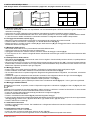
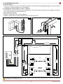


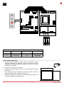
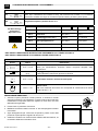
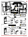
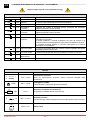

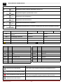
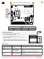
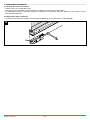
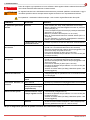
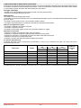
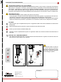
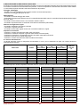

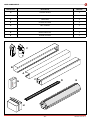
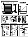
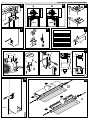
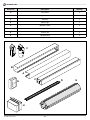

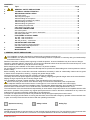
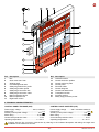
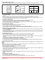

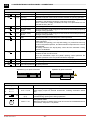
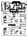
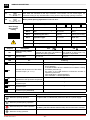
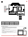
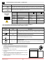

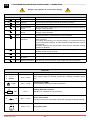
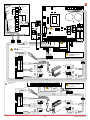
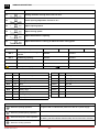
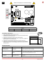

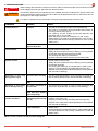
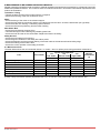
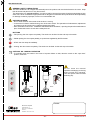
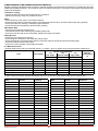


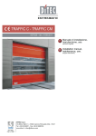

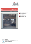
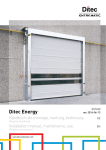
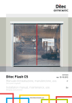
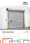
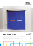
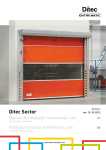
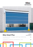

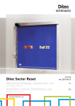
![Documentation technique [1.59 Mo]](http://vs1.manualzilla.com/store/data/006788543_1-357094a5e8900d31cb1a888bc107021d-150x150.png)