1
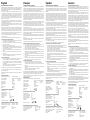
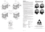
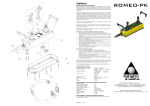
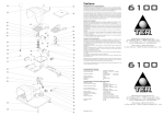
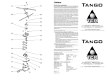
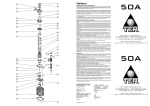
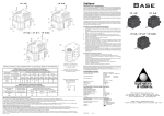
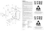
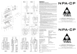
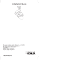
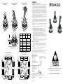
Schema Cablaggio A
Wiring Layout A
Schema Cablaggio B
Schema Cablaggio B
Wiring Layout B
Wiring Layout B
Italiano
Istruzioni d’uso e manutenzione
Il combinatore Romeo è un dispositivo elettromeccanico per circuiti di comando/controllo e
manovra a bassa tensione (EN 60947-1, EN 60947-5-1) da utilizzarsi come equipaggiamento
elettrico di macchine (EN 60204-1) in conformità a quanto previsto dai requisiti essenziali
della Direttiva Bassa tensione 2006/95/CE e della Direttiva Macchine 2006/42/CE.
P2
P3
P4
Il combinatore Romeo è previsto per impiego in ambiente industriale con condizioni climatiche
anche particolarmente gravose (temperature di impiego da –25°C a +70°C ed idoneità
per utilizzo in ambienti tropicali). L’apparecchio non è idoneo per impiego in ambienti con
atmosfere potenzialmente esplosive, in presenza di agenti corrosivi od elevata percentuale
di cloruro di sodio (nebbia salina). Il contatto con oli, acidi e solventi può danneggiare
l’apparecchio; evitare di usarli per operazioni di pulizia. Non è consentito collegare più di
una fase per ogni interruttore. Non oliare od ingrassare gli interruttori e i relativi attuatori.
P5
P2
P1
1
Se i combinatori sono provvisti di blocco meccanico, non manovrare la leva di comando
prima di aver disinserito l’apposito blocco sollevando la parte inferiore del pomolo (01)
questa manovra attiva anche l’interruttore centrale dedicato.
Se i combinatori sono provvisti di pulsante “Uomo Morto” l’abilitazione alle manovre si ottiene
premendo il pulsante (P1), inoltre azionando gli eventuali pulsanti / selettori (P2, P3, P4,
P5) si attivano le funzioni previste.
P1
3
4
5
3
3
4
4
In relazione alle condizioni di installazione, di impiego e alla valutazione dei requisiti essenziali
ai fini della sicurezza e della tutela della salute il combinatore deve essere installato in modo
da garantire adeguata protezione dell’equipaggiamento in generale e delle parti attive in
particolare (protezione contro la scossa elettrica e protezione contro l’ingresso di corpi
solidi e liquidi).
5
5
Romeo
L’installazione del combinatore Romeo deve essere effettuata da personale competente
ed addestrato. I cablaggi elettrici devono essere effettuati a regola d’arte secondo le
disposizioni vigenti.
Prima di eseguire l’installazione e la manutenzione del combinatore Romeo è necessario
togliere l’alimentazione principale della macchina.
Il combinatore è completo di sacchetto accessori che contiene: n°4 viti metriche (04).
Dispositivo 1
Dispositivo 2
Device 1
Dispositivo 3
Device 2
Device 3
Green
1
2
3
Dispositivo
Device
Posizione
Blue
White 50%
Numero Pin
Funzione
Position
Pin number
Function
23
27
26
25
24
22
Red
Disponibile per tutti i modelli
Avaiable for all models
Schema di cablaggio A
17
C
1V
NC
17
C
2V
NC
7
8
NC 1V
C
9
NC 3V
C
17
17
9
16
C
C
A 1V
3V
NC
NC
1
8
16
5
B
3
1V
2V
C
C
16
17
16
3
21
1
NC
18
4
2
2
19
6
4
NC
20
7
NC
20
NO
C
15
13
16
C
C
4V
6V
A 1V
3V
NC
NC
NC
NC
10
12
1
16
C
C
C
1V
NC
17
C
2V
NC
11
5V
NC
14
8
6
NC 1V
C
9
NC 3V
C
Conformità alle Direttive Comunitarie
Conformità alle Norme
Temperatura ambiente
17
17
16
7
6
18
5
17
4
16
3
2
11
3
16
C
C
4V
6V
NC
NC
10
12
NC
NC
NC
B
16
1V
11
22
2V
C
C
16
16
13
NC 4V
C
17
15
NC 6V
C
17
23
15
25
13
27
11
17
C
C
26
12
5V
NC
14
NC
5V
24
14
10
C
7
8
16
4
2
C
12
17
17
9
21 16
5V
14
10
Caratteristiche Tecniche
1
19
16
TER declina ogni responsabilità da danni derivanti dall’uso improprio dell’apparecchio o da
una sua installazione non corretta.
C
D
6
Qualsiasi modifica ai componenti del combinatore annulla la validità dei dati di targa ed
identificazione dell’apparecchio e fa decadere i termini di garanzia. In caso di sostituzione
di un qualsiasi componente utilizzare esclusivamente ricambi originali.
Wiring Layout B
C
D
Operazioni di manutenzione periodica
-
verificare il corretto serraggio delle viti (04) di fissaggio del combinatore sul supporto
-
verificare il corretto funzionamento del blocco meccanico (01) se presente
-
verificare il corretto funzionamento meccanico del pulsante “Uomo Morto”(P1) se
presente
-
verificare il corretto funzionamento meccanico dei pulsanti / selettori (P2, P3, P4, P5)
se presenti
-
verificare le condizioni dei cablaggi (in particolare nella zona dei morsetti)
-
verificare le condizioni del soffietto (03) del combinatore
Schema di cablaggio B
Wiring Layout A
Operazioni per una corretta installazione del combinatore
1-
effettuare la foratura Ø 60 sul supporto prescelto (supporto con spessore di 4 mm)
(per una corretta foratura, utilizzare l’apposita maschera fornita su richiesta)
2-
inserire il combinatore nel foro del supporto (comprimere leggermente il soffietto del
combinatore (03) per un corretto inserimento dell’apparecchio)
3-
posizionare la targhetta (05) provvista di guarnizione sul combinatore
4- avvitare le viti (04) facendo corrispondere i fori della targhetta (05) con quelli
effettuati sul supporto e con quelli filettati sul combinatore (porre attenzione al
corretto posizionamento della guarnizione tra il combinatore ed il supporto)
5-
spelare il cavo multipolare per una lunghezza adeguata alle operazioni di connessione
elettrica con i morsetti
6-
fissare il cavo multipolare in modo da evitare la possibilità di trazione esterna sulle
connessioni
7-
effettuare le connessioni elettriche con i morsetti rispettando lo schema di cablaggio
riportato sul retro delle istruzioni, consigliabile l’impiego di puntali.
Grado di protezione
Categoria di isolamento
Posizioni di funzionamento
Capacità di serraggio del morsetto
Coppia di serraggio del morsetto
2006/95/CE 2006/42/CE
EN 60204-1 EN 60947-1 EN60947-5-1
Immagazzinaggio
-40°C/+70°C
Funzionamento
-25°C/+70°C
IP 00
Classe I
Tutte le posizioni
0,2 / 2,5 mm2
50 /60 cNm
Marcature
C
Caratteristiche Tecniche degli Interruttori
Categoria di impiego
Corrente nominale di impiego
Tensione nominale di impiego
Corrente nominale termica
Tensione nominale di isolamento
Durata meccanica
Connessioni
Marcature e omologazioni
AC 15
2A
48 V~
8A
60 V~
0.5x10⁶ manovre
Morsettiera
16
e
Caratteristiche Tecniche dei Pulsanti / Selettori
13
NC 4V
C
17
15
NC 6V
C
17
Corrente e Tensione nominale di impiego
Corrente e Tensione nominale di impiego
Tensione nominale di isolamento
Durata meccanica
Connessioni
PRIS580100
rev. 02
400mA - 32 Vac Resistivo
100mA - 50Vdc
Resistivo
60 V~
6
0.1x10 manovre
Morsettiera
TER Tecno Elettrica Ravasi s.r.l.
Via Garibaldi 29/31 - 23885 Calco (LC) - Italy
Tel. +39 039 9911011 - Fax +39 039 9910445
E-mail: [email protected] - www.terworld.com
Sede Legale - Registered Office
Via San Vigilio 2 - 23887 Olgiate Molgora (LC) - Italy
English
Français
Español
Deutsch
Use and Maintenance Instructions
Instructions d’Emploi et Entretien
Instrucciones de Uso y Manutención
Betriebs- und Wartungsanweisung
The Romeo joystick is an electromechanical device for low voltage control circuits (EN
60947-1, EN 60947-5-1) to be used as electric equipment on machines (EN 60204-1) in
compliance with the essential requisites of the Low Voltage Directive 2006/95/CE and the
Machine Directive 2006/42/CE.
Le combinateur Romeo est un dispositif électromécanique pour circuits de commande/contrôle
et manœuvre à basse tension (EN 60947-1, EN 60947-5-1) à utiliser comme équipement
électrique sur des machines (EN 60204-1) conformément aux normes essentielles de la
Directive Basse Tension 2006/95/CE et de la Directive Machines 2006/42/CE.
The Romeo joystick is designed for use in industrialal environments even under severe
climatic conditions (working temperatures from -25°C to +70°C and suitable for use
in tropical environments). The equipment is not suitable for use in environments with
potentially explosive atmosphere, corrosive agents or a high percentage of sodium chloride
(saline fog). Oils, acids or solvents may damage the equipment; avoid using them for
cleaning. Do not connect more than one phase to each switch. Do not oil or grease the
switches and the control elements.
Le combinateur Romeo est destiné à être utilisé en milieu industriel y compris dans des
conditions climatiques extrêmes (température d’utilisation entre –25 °C et +70 °C et
apte à l’utilisation en milieu tropical). L’appareil n’est pas destiné à être utilisé en milieu
potentiellement explosif, en présence d’agents corrosifs ou contenant un pourcentage
élevé de chlorure de sodium (brouillard salin). Le contact avec des huiles, des acides ou
des solvants risque d’endommager l’appareil; éviter de les utiliser pour le nettoyage. Il est
interdit de connecter plus d’une phase pour chaque interrupteur. Ne pas huiler ni graisser
les interrupteurs ni leurs actionneurs.
El combinador Romeo es un dispositivo electromecánico para circuitos de mando / control y
maniobra a baja tensión (EN 60947-1, EN 60947-5-1) para ser utilizado como equipamiento
eléctrico de máquinas (EN 60204-1) de conformidad con lo previsto por los requisitos
esenciales de la Directiva de Baja Tensión 2006/95/CE y de la Directiva sobre Máquinas
2006/42/CE.
Der Verbundantrieb Romeo ist eine elektromechanische Vorrichtung für Steuer-/
Regelkreise und Schaltungen mit Niederspannung (EN 60947-1, EN 60947-5-1). Der
Verbundantrieb wird als elektrische Ausrüstung von Maschinen (EN 60204-1) in Konformität
mit den wesentlichen Bestimmungen der Spannungsrichtlinie 2006/95/CE und der
Maschinenrichtlinie 2006/42/CE verwendet.
El combinador Romeo está previsto para el empleo en ambiente industrial, con condiciones
climáticas incluso especialmente dificultosas (temperaturas de empleo de –25 °C a +70 °C e
idoneidad para su utilización en ambientes tropicales). El aparato no resulta adecuado para
su empleo en ambientes con atmósferas potencialmente explosivas, en presencia de agentes
corrosivos o elevado porcentaje de cloruro de sodio (niebla salina). El contacto con aceites,
ácidos y solventes puede dañar el aparato; evitar su uso para operaciones de limpieza.
No está permitido conectar más de una fase por cada interruptor. No aceitar ni engrasar los
interruptores ni los relativos actuadores.
Der Verbundantrieb Romeo ist für den Einsatz in Industrieumgebungen auch unter
besonders schwierigen klimatischen Bedingungen (Einsatztemperatur von -25°C bis
+70°C sowie Einsatz in den Tropen) geeignet. Das Gerät ist dagegen nicht für den Einsatz
in potentiell explosiver Umgebung, in Anwesenheit von korrodierenden Stoffen oder in
Umgebungen mit hohem Gehalt an Salz (Salznebel) geeignet. Der Kontakt mit Öl, Säuren
und Lösemitteln kann zu einer Beschädigung des Geräts führen; Vermeiden Sie für die
Reinigung. Es ist verboten, mehr als eine Phase pro Schalter anzuschließen. Die Schalter
und die entsprechenden Antriebe nicht ölen oder schmieren.
Si los combinadores están dotados de bloqueo mecánico, no maniobrar la palanca de mando
antes de haber desconectado el bloqueo correspondiente elevando la parte inferior del pomo
(01), esta maniobra también activa el interruptor correspondiente central.
Si los combinadores están dotados de pulsador “Hombre Muerto”, apretar sobre el pulsador
(P1) para permitir las maniobras, operando los eventuales botones / selectores (P2, P3, P4,
P5), las funzione previstas son activadas.
Wenn Verbundantriebe mit mechanischer Sperre ausgestattet sind, darf der Steuerhebel
nicht bewegt werden, bevor die entsprechende Sperre durch Hochziehen des Knaufunterteils
(01) entriegelt wurde, Dies Betrieb aktiviert auch den zentralen Schalter.
Bei dem Fall sind die Verbundantriebe mit Drucktaste „Betrieber abwesend” ausgerüstet,
wird die Betrieb beim Drücken der Taste (P1) ermöglicht, Bei aktivieren der Tasten /
Selektoren (P2, P3, P4, P5) werden die vorgesehene Funktionen aktiviert.
En relación con las condiciones de instalación, de empleo y en base a la valoración de los
requisitos esenciales a fines de la seguridad y la protección de la salud, el combinador debe
ser instalado de tal forma que garantice adecuada protección del equipamiento en general y
de las partes activas en particular (protección contra la sacudida eléctrica y protección contra
la entrada de cuerpos sólidos y líquidos).
Bezüglich der Installations- und Einsatzbedingungen sowie der Erfüllung der
wesentlichen Anforderungen und Voraussetzungen hinsichtlich der Sicherheit und des
Gesundheitsschutzes muss der Verbundantrieb derart installiert werden, dass ein geeigneter
Schutz der Ausrüstung im Allgemeinen und insbesondere der aktiven Teile gewährleistet
ist (Schutz gegen Stromschlag und Schutz gegen das Eindringen fester Körper und von
Flüssigkeiten).
If the joysticks are equipped with mechanical interlock, do not move the control lever
before removing this block by lifting the lower part of the knob (01), this operations also
activates the dedicated central switch.
If the joysticks are equipped with the “Dead Man” button, push the button (P1) to enable
movement and while operating eventual push buttons / selectors (P2, P3, P4, P5) the
foreseen functions are activated.
With regard to the conditions for installation, use and evaluation of the essential requisite
for safety and the protection of health, the joystick must be installed so as to ensure
adequate protection of the equipment in general and of the active parts in particular
(protection against electric shock and against the penetration of solid bodies and liquids).
The installation of the Romeo joystick shall be carried out by expert and trained personnel.
Wiring shall be properly done according to the current instructions.
Prior to the installation and the maintenance of the joystick, the main power of the machinery shall be turned off.
The joystick is supplied with a bag of accessories including: 4 metric screws (04).
Steps for the proper installation of the joystick
1-
drill holes Ø 60 on the chosen support (support with a thickness of 4 mm) (for correct
drilling use the special template supplied on request)
2-
place the joystick in the hole on the support (press the bellows on the joystick (3)
slightly for correct insertion)
3-
position the plate (05) with its gasket on the joystick
4-
fasten the screws (04) matching the holes on the plate (05) with those on the support
and the threaded holes on the joystick (take care to position the gasket correctly
between the joystick and the support)
5-
strip the multi-pole cable for a length sufficient for electrical connection with the
terminals
6-
fasten the multi-pole cable so as to prevent the possibility of external traction on
the connections
7- connect the wires to the terminals in accordance with the wiring diagram shown on
the instructions; we suggest the use of pin terminals
Steps for routine maintenance
-
check the correct tightening of the screws (04) fastening the joystick to the support
-
if there is a mechanical interlock (01), make sure it functions correctly
-
if there is a “Dead Man” button (P1), make sure it mechanically functions correctly
-
if there are a push buttons / selectors (P2, P3, P4, P5), make sure they mechanically
functions correctly
-
check the conditions of the wiring (in particular where wires clamp into the terminals)
-
check the conditions of the bellows (03) on the joystick
Any change to parts of the joystick will invalidate the rating plate and identification data
of the device, and render the warranty null and void. In case of replacement of any part,
use original spare parts only.
TER declines all responsibility for damages caused by the improper use or installation of
the equipment.
Technical Specifications
Conformity to Community Directives
Conformity to Standards
Ambient temperature
Protection degree
Insulation category
Operating positions
Wires
Tightening torque
2006/95/CE 2006/42/CE
EN 60204-1 EN 60947-1 EN60947-5-1
Storage
-40°C/+70°C
Operational
-25°C/+70°C
IP 00
Class I
Any position
0.2 /2.5 mm2
50/60 cNm
Markings
C
Technical Specifications of the Switches
Utilisation category
Rated operational current
Rated operational voltage
Rated thermal current
Rated insulation voltage
Mechanical life
Connections
AC 15
2A
48 V~
8A
60 V~
0.5x10⁶ operations
Terminals
Markings and homologations
e
Technical Specifications of the Push Buttons / Selectors
Rated operational current and voltage
Rated operational current and voltage
Rated insulation voltage
Mechanical life
Connections
400mA - 32 Vac
Resistive
100mA - 50 Vdc
Resistive
60 V~
0.1x10⁶ operations
Terminals
Si les combinateurs sont pourvus de blocage mécanique, ne pas manœuvre le levier de
commande avant d’avoir déverrouillé le blocage en soulevant la partie basse de la poignée
(01), cette manœuvre permet également d’activer l’interrupteur central dedié.
Si les combinateurs sont pourvus de poussoir «Homme Mort», pousser le bouton (P1) pour
permettre le manœuvres et exploitater eventuels poussoirs / sélecteurs (P2, P3, P4, P5)
on active les fonctions prevues.
En fonction des conditions d’installation, d’utilisation et de l’évaluation des exigences
essentielles en matière de sécurité et de protection sanitaires, le combinateur doit être
installé de manière à garantir la protection appropriée de l’équipement en général et des
parties actives en particulier (protection contre les décharges électriques et protection contre
l’entrée de corps solides et liquides).
L’installation du combinateur Romeo doit être confiée à un personnel compétent et formé.
Les câblages électriques doivent être effectués dans les règles de l’art selon les dispositions
en vigueur.
Toujours couper l’alimentation principale de la machine avant de procéder à l’installation
et à l’entretien du combinateur Romeo.
Le combinateur est équipé avec sac accessoire contenant : n°4 vis métriques (04).
Opérations permettant une installation correcte du combinateur
1-
Percer un orifice de Ø 60 sur le support préchoisi (support d’une épaisseur de 4 mm)
(pour un perçage correct, utiliser le gabarit fourni sur demande)
2-
enfiler le combinateur dans l’orifice du support (comprimer légèrement le soufflet
(03) du combinateur pour bien enfoncer l’appareil)
3-
positionner la plaquette (05) avec son joint sur le combinateur
4-
visser les vis (04) en faisant correspondre les orifices de la plaquette (05) avec
ceux effectués sur le support et avec ceux filetés sur le combinateur (veiller à bien
positionner le joint entre le combinateur et le support)
5- dénuder le câble multipolaire sur la longueur nécessaire à sa connexion électrique
avec les bornes
6-
fixer le câble multipolaire de manière à éviter toute traction externe possible sur les
connexions
7- effectuer les connexions électriques avec les bornes en respectant le schéma de
cablage figurant sur les instructions; on conseil l’utilisation de cosses
Opérations d’entretien périodique
-
vérifier le serrage des vis (04) de fixation du combinateur sur le support
-
en presence du blocage mécanique (01) vérifier son bon fonctionnement
-
en presence du poussoir «Homme Mort» (P1) vérifier son bon fonctionnement
mécanique
-
en presence des poussoirs / sélecteurs (P2, P3, P4, P5) vérifier son bon fonctionnement
mécanique
-
vérifier l’état des câblages (notamment dans la zone des bornes)
-
vérifier l’état du soufflet (03) du combinateur
Toute modification apportée aux composants du combinateur annule la validité des données
de la plaquette signalétique de l’appareil et invalide la garantie. Lors du remplacement d’un
composant quelconque, utiliser exclusivement des pièces de rechange originales.
TER décline toute responsabilité en cas de dommages provoqués par l’usage impropre ou
la mauvaise utilisation de l’appareil.
Données Techniques
Conformité aux Directives Communautaires
Conformité aux Normes
Température ambiante
Degré de protection
Catégorie d’isolement
Positions de fonctionnement
Capacité de serrage
Couple de torsion
2006/95/CE 2006/42/CE
EN 60204-1 EN 60947-1 EN60947-5-1
Stockage
-40°C/+70°C
Fonctionnement
-25°C/+70°C
IP 00
Groupe I
Toutes les positions
0.2 / 2.5 mm2
50/60 cNm
Marquage
C
Données Techniques des Interrupteurs
Catégorie d’utilisation
Courant nominal d’utilisation
Tension nominale d’utilisation
Courant nominal thermique
Tension nominale d’isolement
Durée mécanique
Connexions
AC 15
2A
48 V~
8A
60 V~
0.5x10⁶ manoeuvres
Terminals
Marquage et homologation
e
Données Techniques des Poussoirs / Sélecteurs
Courant et tension nominal d’utilisation
Courant et tension nominal d’utilisation
Tension nominale d’isolement
Durée mécanique
Connexions
400mA - 32 Vac Résistif
100mA - 50 Vdc Résistif
60 V~
0.1x10⁶ manoeuvres
Terminals
La instalación del combinador Romeo debe ser efectuada por personal competente y preparado.
Los cableados eléctricos tienen que efectuarse según la regla del arte, de conformidad con las
disposiciones vigentes.
Antes de efectuar la instalación y el mantenimiento del combinador Romeo, es necesario quitar
la alimentación principal de la máquina.
El combinador tiene bolsa de accesorios completa de: n°4 tornillos métricos (04).
Operaciones para una correcta instalación del combinador
1-
efectuar la perforación Ø 60 en el soporte elegido (soporte con espesor de 4 mm) (para
una perforación correcta, utilizar la plantilla suministrada bajo pedido)
2-
insertar el combinador en el agujero del soporte (comprimir ligeramente el fuelle del
combinador (03) para una correcta inserción del aparato)
3-
poner la plaquita (05) con su junta sobre el combinador
4- enroscar los tornillos (04) haciendo casar los agujeros de la plaquita (05) con los
efectuados en el soporte y con los roscados en el combinador (prestar atención al
correcto posicionamiento de la junta entre el combinador y el soporte)
5-
pelar el cable multipolar por una longitud adecuada a las operaciones de conexión eléctrica
con los bornes
6-
fijar el cable multipolar de tal forma que se evite la posibilidad de tracción externa sobre
las conexiones
7-
llevar a cabo las conexiones eléctricas con los bornes respetando el esquema de cableado
presente en las instrucciones; se aconseja utilizar terminales
Operaciones de mantenimiento periódico
-
verificar el correcto apretamiento de los tornillos (04) de fijación del combinador sobre
el soporte
-
en presencia de bloqueo mecánico (01) verificar su correcto funcionamiento
-
en presencia de pulsador “Hombre Muerto” (P1) verificar su correcto funcionamiento
mecánico
-
en presencia des pulsadores / selectores (P2, P3, P4, P5) verificar su correcto
funcionamiento mecánico
-
verificar las condiciones de los cableados (sobre todo en la zona de los bornes)
- verificar las condiciones del fuelle (03) del combinador
Cualquier modificación a los componentes del combinador anula la validez de los datos de
matrícula e identificación del aparato y revoca los términos de garantía. En caso de sustitución
de cualquier componente, utilicen exclusivamente repuestos originales.
TER declina toda responsabilidad por daños derivados del uso impropio del aparato o de su
instalación incorrecta.
Características Técnicas
Conformidad a las Normas Comunitarias
Conformidad a las Normas
Temperatura ambiente
Grado de protección
Categoría de aislamiento
Posiciones de funcionamiento
Capacidad de apretamiento
Par de torsión
2006/95/CE 2006/42/CE
EN 60204-1 EN 60947-1 EN60947-5-1
Almacenaje
-40°C/+70°C
Funcionamiento
-25°C/+70°C
IP 00
Clase I
Todas las posiciones
0.2 / 2.5 mm2
50 / 60 cNm
Marcado
C
Características Técnicas de los Interruptores
Categoría de empleo
Corriente nominal de empleo
Tensión nominal de empleo
Corriente nominal térmica
Tensión nominal de aislamiento
Duración mecánica
Conexiones
AC 15
2A
48 V~
8A
60 V~
0.5x10⁶ maniobras
Bornes
Marcado y homologaciones
e
Características Técnicas de los Butones / Selectores
Corriente y tensión nominal de empleo
Corriente y tensión nominal de empleo
Tensión nominal de aislamiento
Duración mecánica
Conexiones
400mA - 32 Vac Resistiva
100mA - 50 Vdc Resistiva
60 V~
0.1x10⁶ maniobras
Bornes
Der Verbundantrieb Romeo muss von kompetentem, entsprechend ausgebildetem
Fachpersonal installiert werden. Die Verkabelung muss kunstgerecht gemäß den geltenden
Bestimmungen und Gesetzen ausgeführt werden.
Vor der Installation und der Wartung des Verbundantriebs Romeo muss die Stromversorgung
der Maschine unterbrochen werden.
Die Verbundantrieb ist komplett mit Zubehörbeutel und enthält: Nr. 4 metrischen Schrauben (04)
Korrekte Installation des Verbundantriebs
1- eine Bohrung Ø 60 an der gewählten Halterung (Dicke 4 mm) herstellen (zum
korrekten Anbohren die auf Anfrage gelieferte spezielle Schablone verwenden)
2- den Verbundantrieb in die Bohrung der Halterung einsetzen (den Faltenbalg des
Verbundantriebs (03) leicht zusammendrücken, damit das Gerät korrekt eingesetzt
werden kann)
3-
das Schild (05) mit Dichtung am Verbundantrieb anbringen
4-
die Schrauben (04) festziehen. Dabei müssen die Befestigungslöcher des Schildes
(05) mit den an der Halterung erstellten Löchern und mit den Gewindelöchern am
Verbundantrieb übereinstimmen (aufpassen, dass die Dichtung korrekt zwischen
Verbundantrieb und Halterung eingesetzt wird)
5- das Mehrleiterkabel so weit abisolieren, dass der es korrekt an die Klemme
angeschlossen werden kann
6-
das Mehrleiterkabel befestigen, damit keine externe Zugwirkung auf die Anschlüsse
ausgeübt wird
7- durchführen die elektrische Anschlüsse mit den Klemmen gemäß dem Schaltplan
auf die Betriebsanleitung; Verwendung von Kabelschuhen empfehlbar
Regelmäßige Wartungsarbeiten
überprüfen, dass die Feststellschrauben (04) des Verbundantriebs am Halter korrekt
festgezogen sind.
überprüfen Sie den richtigen Betrieb der mechanische Sperre (01), ob dies anwesend ist
überprüfen den richtigen mechanischen Betrieb der Taste „Betrieber abwesend” (P1),
ob dies anwesend ist
überprüfen den richtigen mechanischen Betrieb der Tasten / Selektoren (P2, P3, P4,
P5), ob dies anwesend ist
den Zustand der Kabel überprüfen (insbesondere im Befestigungsbereich der Klemme).
den Zustand des Verbundantriebfaltenbalgs (03) überprüfen.
Alle an den Bauteilen des Verbundantriebs durchgeführten Abänderungen führen zur
Ungültigkeit der Schilddaten und der Kenndaten des Geräts sowie zum Verfall der Garantie.
Alle Bauteile müssen durch Originalersatzteile ausgetauscht werden.
TER haftet nicht für Schäden, die auf den unsachgemäßen Gebrauch oder eine falsche
Installation des Geräts zurückzuführen sind.
Technische Eigenschaften
Einhaltung der Gemeinschaftsrichtlinien
Einhaltung der Normen
Umgebungstemperatur
Schutzart
Isolierklasse
Betriebsstellungen
Festziehleistung
Drehmoment
2006/95/CE 2006/42/CE
EN 60204-1 EN 60947-1 EN60947-5-1
Lagerung
-40°C/+70°C
Betrieb
-25°C/+70°C
IP 00
Klasse I
Alle Stellungen
0.2 / 2.5 mm2
50 / 60 cNm
Kennzeichnung
C
Technische Eigenschaften der Schalter
Einsatzklasse
Nennbetriebsstrom
Nennbetriebsspannung
Nennthermostrom
Nennisolierspannung
Mechanische Lebensdauer
Anschlüsse
Kennzeichnung und Zulassungen
AC 15
2A
48 V~
8A
60 V~
0.5x10⁶ Schaltungen
Schraubklemme
e
Technische Eigenschaften der druck Tasten / Selektoren
Nennbetriebsstrom -spannung
Nennbetriebsstrom -spannung
Nennisolierspannung
Mechanische Lebensdauer
Anschlüsse
400mA - 32 Vac Resistive
100mA - 50 Vdc Resistive
60 V~
0.1x10⁶ Schaltungen
Schraubklemme