1
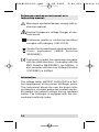
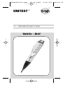
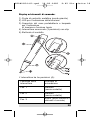
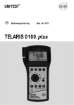
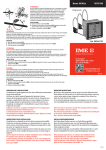
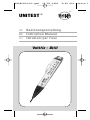
PTDB2054-02.qxd
20.09.2005
9:05 Uhr
®
UNITEST
®
Bedienungsanleitung
Instruction Manual
Istruzioni per l'uso
Voltfix - Drill
Seite 1
PTDB2054-02.qxd
20.09.2005
9:05 Uhr
Symbolerklärung
Warnung vor einer Gefahrenstelle. Bedienungsanleitung beachten.
Vorsicht! Gefährliche Spannung, Gefahr des
elektrischen Schlages.
Durchgängige doppelte oder verstärkte
Isolierung entsprechend Schutzklasse II IEC
61140.
Kennzeichnung elektrischer und elektronischer Geräte (WEEE Richtlinie 2002/96/EG).
Konformitätszeichen, bestätigt die Einhaltung der gültigen Richtlinien. Die EMVRichtlinie (89/336/EWG) werden eingehalten. Die Niederspannungsrichtlinie (73/23/
EWG) wird ebenfalls eingehalten.
Einleitung:
Der Spannungsprüfer UNITEST Voltfix Drill ist
eine Weiterentwicklung der bewährten VoltfingerBaureihe und ermöglicht dem Anwender neben
der indirekten Spannungsprüfung an isolierten
Kabeln auch die direkte Spannungserkennung
über Metallspitze und Berührungselektrode.
Weiterhin ist ein Durchgangsprüfer eingebaut.
2
Seite 2
PTDB2054-02.qxd
20.09.2005
9:05 Uhr
Leistungsmerkmale:
• Berührungslose Spannungsprüfung
50 V ... 600 V AC.
• Direkte Spannungsprüfung über Metallspitze u.
Berührungselektrode von 50 V...600 V AC.
• Einfache Durchgangsprüferfunktion.
• Auffinden von Leitungsunterbrechungen in
isolierten Kabel und Leitungen.
• Phasenprüfer an Steckdosen.
• Anzeige mittels Leuchtdiode (blinkend) und
akustisches Tonsignal (pulsierend).
• Integrierte Taschenlampe.
• Automatischer Eigentest bei Inbetriebnahme.
• Kompakte handliche Bauform.
Sicherheitsmaßnahmen
Das Gerät hat unser Werk in sicherheitstechnisch
einwandfreiem Zustand verlassen. Um diesen
Zustand zu erhalten, muß der Anwender die
Sicherheitshinweise in dieser Anleitung beachten.
Achtung!
Die Bedienungsanleitung enthält Informationen
und Hinweise, die zu einer sicheren Bedienung
und Nutzung des Gerätes notwendig sind. Vor
der Verwendung des Gerätes ist die
Bedienungsanleitung aufmerksam zu lesen und
in allen Punkten zu verstehen und zu befolgen.
Wird die Anleitung nicht beachtet oder sollten Sie
es versäumen, die Warnungen und Hinweise zu
beachten, können ernste oder lebensgefährliche
Verletzungen bzw. Beschädigungen des Gerätes
eintreten.
3
Seite 3
PTDB2054-02.qxd
20.09.2005
9:05 Uhr
Achtung!
Bei Spannungsmessungen jeder Art darf das
Gerät nur am Handgriff angefaßt werden.
Achtung!
Eine einwandfreie Funktion ist nur innerhalb dem
in den technischen Daten angegebenen
Temperaturbereich gewährleistet.
Achtung!
Vor jeder Benutzung muß das Gerät auf einwandfreie Funktion (z.B. an einer bekannten
Stromquelle) geprüft werden.
Vorsicht!
Vor dem Öffnen (z.B. für Batteriewechsel) muß
das Gerät von allen Stromkreisen getrennt werden.
Achtung!
Das Gerät darf von unbefugten Personen nicht
geöffnet oder zerlegt werden.
Achtung!
Bestimmungsgemäße Verwendung:
Das Gerät darf nur unter den Bedingungen und
für die Zwecke eingesetzt werden, für die es konstruiert wurde. Hierzu sind besonders die Sicherheitshinweise, die Technischen Daten mit den
Umgebungsbedingungen und die Verwendung in
trockener Umgebung zu beachten.
4
Seite 4
PTDB2054-02.qxd
20.09.2005
9:05 Uhr
Anzeige und Bedienelemente:
1) Metallprüfspitze (Schraubendreherspitze)
2) LED für Spannungsanzeige
3) Batteriefachdeckel und Lampe für Spannungsanzeige und Taschenlampenfunktion
4) Schiebeschalter (3 Positionen) mit Klipp
5) Berührungselektrode
Der Schalter (4) hat drei Positionen:
Schalterstellung
Messprinzip
Pos. 1
indirekt (kontaktlos)
Pos. 2
indirekt (kontaktlos)
Pos. 3
Direkt (Metallspitze und
Berührungselektrode)
5
Seite 5
PTDB2054-02.qxd
20.09.2005
9:05 Uhr
Durchführen von Wechselspannungsprüfungen:
Vorsicht!
Um einen elektrischen Schlag zu vermeiden, sind
unbedingt die geltenden Sicherheits- und VDEBestimmungen bezüglich zu hoher Berührungsspannung zu beachten, wenn mit Spannungen
größer 120 V (60 V) oder 50 V (25 V) eff AC gearbeitet wird. Die Werte in Klammern gelten für eingeschränkte Bereiche (wie z.B. Medizin,
Landwirtschaft).
Achtung!
Der Spannungsprüfer ist für Wechselspannungen zwischen 50 V und 600 V konstruiert. Eine
einwandfreie Funktion ist nur im Temperaturbereich von 0...40°C <80% Feuchte gewährleistet.
Achtung!
Das Gerät darf nicht zum Feststellen der
Spannungsfreiheit in elektrischen Anlagen eingesetzt werden. Bei abgeschirmten Leitungen oder
Geräten ist eine indirekte Spannungsprüfung
(kontaktlos) nicht oder nur eingeschränkt möglich.
Berührungslose (indirekte) Spannungsprüfungen
Diese Messart ist in den Schalterstellungen Pos.1
+ 2 möglich und beinhaltet die kontaktlose
Spannungserkennung von isolierten Kabel,
Leitung oder Geräten die ein elektromagnetisches Feld aussenden. Weiterhin können hiermit
auch Unterbrechungen in Kabeln erkannt werden.
Bei der Prüfung von Netzanschlußkabel auf
Unterbrechung ist zu beachten, daß beide
Leitungen einmal an die Phase (L) angeschlossen werden (Schukostecker um 180° drehen).
6
Seite 6
PTDB2054-02.qxd
20.09.2005
9:05 Uhr
Direkte Spannungserkennung
(Kontakt über Metallspitze und Berührungselektrode)
Im Gegensatz zur berührungslosen Spannungserkennung erfolgt unter Pos.3 die direkte
Spannungsprüfung an der leitenden Oberfläche
des Messobjektes.
Hierzu muss die Metallspitze auf den Messpunkt
aufgesetzt werden und der Anwender muss die
Berührungselektrode kontaktieren.
Schalter- Messprinzip Funktionen
stellung
Pos. 1
Pos. 2
Pos. 3
Kontaktlose
Indirekt
(kontaktlos) Spannungserkennung
LED blinkt und Signal
ertönt!
Taschenlampe ist eingeschaltet.
Kontaktlose
Indirekt
(kontaktlos) Spannungserkennung
LED blinkt, Signal ertönt
und Taschenlampe blinkt
Direkt
(Metallspitze
und
Berührungsel
ektrode
Kontaktbezogene
Spannungsprüfung
LED blinkt Signal ertönt
und Taschenlampe blinkt
Durchgangsprüferfunktion
ist aktiv (Messobjekt muß
spannungsfrei sein)
7
Seite 7
PTDB2054-02.qxd
20.09.2005
9:05 Uhr
Anwendungsbeispiele
"Indirekte Spannungsprüfung":
Spannungsprüfung
ohne abisolieren
Auffinden von Leitungsunterbrechung z.B. Kabeltrommel usw.
Anwendungsbeispiele
" Direkte Spannungsprüfung":
Phasenfinder an Steck- und Abzweigdosen
Spannungsprüfung an Sicherungsautomaten
Durchgangsprüferfunktion
In der Schalterstellung Pos.3 ist eine einfache
8
Seite 8
PTDB2054-02.qxd
20.09.2005
9:05 Uhr
Durchgangsprüferfunktion integriert (Metallspitze - Messobjekt - Anwender - Berührungselektrode). Hiermit lassen sich zum Beispiel
Sicherungen, Lampen, Leitungen usw. auf
Durchgang prüfen.
Durchgangsprüfung bei Sicherungen
Wartung:
Das Gerät benötigt bei einem Betrieb gemäß der
Bedienungsanleitung keine besondere Wartung.
Reinigung
Sollte das Gerät durch den täglichen Gebrauch
schmutzig geworden sein, kann das Gerät mit
einem feuchten Tuch und etwas milden
Haushaltsreiniger gereinigt werden.
Verwenden Sie niemals scharfe Reiniger oder
Lösungsmittel.
Batteriewechsel
1) Schalterstellung auf Pos.1 stellen und die
Batteriekappe (3) mit einem Schraubendreher
o.ä. öffnen
9
Seite 9
PTDB2054-02.qxd
20.09.2005
9:05 Uhr
2) Die alten Batterien durch neue ersetzen, dabei
Polarität beachten! Batterietyp siehe techn.Daten.
3) Batteriekappe vorsichtig aufdrücken bis zur
Einrastung.
Batteriedeckel schließen
Achtung!
Wird das Gerät über einen längeren Zeitraum
nicht benutzt, muß die Batterie entnommen werden. Sollte es zu einer Verunreinigung des
Gerätes durch ausgelaufene Batterien gekommen
sein, muß das Gerät zur Reinigung und Überprüfung ins Werk eingesandt werden.
Bitte denken Sie an dieser Stelle auch an unsere
Umwelt. Werfen Sie verbrauchte Batterien nicht
in den normalen Hausmüll, sondern geben Sie
die Batterien bei Sondermülldeponien ab.
Achtung!
Es müssen die jeweils gültigen Bestimmungen
bzgl. der Rücknahme, Verwertung und
Beseitigung von gebrauchten Batterien und
Akkumulatoren beachtet werden.
10
Seite 10
PTDB2054-02.qxd
20.09.2005
9:05 Uhr
Technische Daten
(gültig für 23°C ±5°C, < 80% rel. Luftfeuchte)
Spannungsbereich:
Frequenzbereich:
Durchgangstest:
Anzeige:
Schutzart:
Temperaturbereich:
50 V...600 V AC
50 Hz...500 Hz
0...3 MΩ
Optisch mit blinkender
LED / Lampe und
Signalton pulsierend
IP 40
0°C...40°C < 80%
Feuchte
Überspannungskategorie: CAT III / 600 V gegen Erde
Verschmutzungsgrad: 2
Meereshöhe:
bis 2000 m
Stromversorgung:
2 x 1,5 V Batterien
(Micro) IEC LR03
Maße:
160 x 25 x 21 mm
Gewicht:
ca. 55 g
11
Seite 11
PTDB2054-02.qxd
20.09.2005
9:05 Uhr
24 Monate Garantie
Die Geräte unterliegen einer strengen Qualitätskontrolle. Sollten während der täglichen Praxis
dennoch Fehler in der Funktion auftreten, gewähren wir eine Garantie von 24 Monaten (nur gültig
mit Rechnung).
Fabrikations- oder Materialfehler werden von uns
kostenlos beseitigt sofern das Gerät ohne Fremdeinwirkung und ungeöffnet an uns zurückgesandt
wird.
Beschädigungen durch Sturz oder falsche Handhabung sind vom Garantieanspruch ausgeschlossen.
Treten nach Ablauf der Garantiezeit Funktionsfehler auf, wird unser Werksservice Ihr Gerät
unverzüglich wieder instandsetzen.
Diese Bedienungsanleitung wurde mit großer
Sorgfalt erstellt. Für die Richtigkeit und
Vollständigkeit der Daten, Abbildungen und
Zeichnungen wird keine Gewähr übernommen.
12
Seite 12
PTDB2054-02.qxd
20.09.2005
9:05 Uhr
®
UNITEST
®
Instruction Manual
Istruzioni per l'uso
Voltfix - Drill
Seite 13
PTDB2054-02.qxd
20.09.2005
9:05 Uhr
References marked on instrument or in
instruction manual:
Warning of a potential danger, comply with instruction manual.
Caution! Dangerous voltage. Danger of electrical shock.
Continuous double or reinforced insulation
complies with category II IEC 61140.
Symbol for the marking of electrical and electronic equipment (WEEE Directive
2002/96/EC).
Conformity symbol, the instrument complies
with the valid directives. It complies with the
EMV Directive (89/336/EEC), are fulfilled. It
also complies with the Low Voltage Directive
(73/23/EEC) is fulfilled.
Introduction
The voltage tester UNITEST Voltfix Drill is a further development of the proven Voltfinger series.
This instrument allows the user the direct voltage detection via metal probe and contact electrode besides the indirect voltage test on insulated
cables. The Voltfinger is equipped with the conventional continuity tester.
14
Seite 14
PTDB2054-02.qxd
20.09.2005
9:05 Uhr
Features:
• Contact-free voltage test 50 V...600 V AC
• Direct voltage testing via metal probe and contact electrode from 50 V... 600 V
• Easy continuity test.
• Locating line interruptions in insulated cables
and conductors
• Phase tester of sockets
• Display via LED (blinking) and acoustical signal (pulsing).
• Torch function
• Automatic self test
• Compact and handy
Safety Measures
The instrument has left our factory in a safe and
perfect condition. To maintain this condition, the
user must pay attention to the safety references
contained in this instruction manual.
The instruction manual contains information
and references, necessary for safe operation and
maintenance of the instrument.
Prior to using the instrument the user is kindly requested to thoroughly read the instruction manual and comply with it in all sections.
Failure to read the instruction manual or to
comply with the warnings and references contained herein can result in serious personal
injury or damage to instrument.
15
Seite 15
PTDB2054-02.qxd
20.09.2005
9:05 Uhr
Only touch the instrument at handle surface
provided.
The instrument may only be used within the
operating ranges specified in the technical data
section.
Before batteries are replaced the instrument
must be disconnected from all live circuits.
The instrument may only be opened by professionals.
Appropriate Usage
The instrument may only be used under those
conditions and for those purposes for which it
was developed. For this reason, particular attention must be paid to and instructions must be followed regarding the safety references
the technical data - including environmental conditions and, usage in dry environments.
If the instrument is modified or changed in any
way its operational safety is no longer guaranteed.
16
Seite 16
PTDB2054-02.qxd
20.09.2005
9:05 Uhr
Display and Operation Elements
1) Metal test probe (screw driver probe)
2) LED for voltage indication
3) Battery case and lamp for voltage display
and torch function
4) Slide switch (3 positions) with clip
5) Contact electrode
The switch (4) has three positions
Switch position
Measurement Principal
Pos. 1
indirect contactless
Pos. 2
indirect contactless
Pos. 3
direct (metal probe and
contact electrode)
17
Seite 17
PTDB2054-02.qxd
20.09.2005
9:05 Uhr
Carrying out voltage measurement AC
In order to avoid electrical shock, the valid
safety and VDE regulations regarding excessive
contact voltages must receive utmost attention,
when working with voltages exceeding 120 V
(60 V) DC or 50 V (25 V)rms AC. The values in
brackets are valid for limited ranges e.g., medicine and agriculture).
Attention
The voltage tester is appropriate for AC voltages
between 50 V and 600 V AC. A perfect instrument
function is only ensured within a temperature
range of 0 ... 40°C, <80 % humidity.
Attention
The instrument may not be used to prove the
absence of voltage in electrical systems. When
working with sheathed conductors or instrument, the indirect voltage test (contact-free) is
either impossible or only feasible considering
certain restrictions.
Contactless (indirect) voltage testing
This kind of measurement is possible with switch
pos. 1 + 2 and covers contactless voltage detection of insulated cables, leads or instruments
which send electric magnetic fields. In addition
cable interruptions can be detected.
When testing mains connecting cables for interruptions the user must ensure that both lines are
connected to phase (L). (Turn plugs by 180°).
18
Seite 18
PTDB2054-02.qxd
20.09.2005
9:05 Uhr
Direct voltage indication
(Contact via metal probe and contact electrode)
Direct voltage testing on the conducting UUT
surface can be carried out by selecting position 3
(different to contact-free voltage detection).
For this purpose, place the metal probe onto the
measurement spot whilst touching the contact
electrode.
Switch- Measuring
Position
Principal Function
Position
Pos. 1
Indirect
Contactless voltage
(contactless) detection
LED is blinking and signal is audible!
Torch function is active
Pos. 2
Contactless voltage
Indirect
(contactless) detection
LED is blinking and signal is audible! Torch
function is blinking
Pos. 3
Direct
Contacting voltage
(metal probe testing
and Contact LED is blinking signal is
audible. Torch function is
electrode)
blinking. Continuity is
active (UUT must be voltage free)
19
Seite 19
PTDB2054-02.qxd
20.09.2005
9:05 Uhr
Working example
"Indirect voltage testing":
Voltage test at Insulated
conductors
Locating line interruption
l.e. cable drums etc.
Working example
" Direct voltage testing":
Phase finding on socket aoutlets
Voltage measurement at automatic circuit breaker
Continuity testing
A simple continuity tester function is integrated
position 3 (metal probe – UUT – user – contact
electrode). This function is used to test e.g. fuses,
20
Seite 20
PTDB2054-02.qxd
20.09.2005
9:05 Uhr
lamps, conductors, etc. for continuity.
Continuity test at fuses
Maintenance
When using the instrument in compliance with
the instruction manual, no special maintenance is
required.
Cleaning
If the instrument is dirty after daily use, it is advised that it be cleaned using a damp cloth and a
mild household detergent.
Never use acid detergents or solvents for cleaning.
Battery replacement
1) Set the switch to position 1, press and push
lightly to open.
2) Remove discharged batteries and insert new
ones while respecting correct polarity. For bat21
Seite 21
PTDB2054-02.qxd
20.09.2005
9:05 Uhr
tery type, please refer to the technical data section.
3) Carefully press battery case cover until latching.
Close battery cover
If an instrument is not being used over an extended period of time, the batteries should be removed. If the instrument is contaminated by leaking
batteries, the instrument should be returned to
the factory for cleaning and inspection.
Please consider your environment when you
dispose of your batteries. They belong in a rubbish dump for hazardous waste. In most cases,
the batteries can be returned to their point of
sale.
Please, comply with the current regulations concerning the return, recycling and disposal of used
batteries.
22
Seite 22
PTDB2054-02.qxd
20.09.2005
9:05 Uhr
Technical Data
(for 23°C ±5°C, < 80% rel. humidity)
Voltage range:
Frequency range:
Continuity test:
Display:
50 V...600 V AC
50 Hz...500 Hz
0...3 MΩ
Clear, omnidirectional
flashing beacon
IP-Protection:
IP 40
Temperature range:
0°C up to 40°C
Overvoltage category: CAT III, 600 V against
ground
Pollution degree:
2
Altitude:
up to 2000 m
Power supply:
2 x 1,5 V Batterien
(Micro) IEC LR03
Dimensions:
160 x 25 x 21 mm
Weight:
approx. 55 g
23
Seite 23
PTDB2054-02.qxd
20.09.2005
9:05 Uhr
24 Month Guarantee:
The instruments are subject to stringent quality
controls. If, in the course of normal use, a fault
should occur, it is covered by our 24 Month
Guarantee (valid only with invoice). Faults in
manufacture and materials will be rectified by us
free of charge, provided the instrument has not
been tampered with, and is returned to us unopened. Damage due to dropping, abuse or misuse
is not covered by the guarantee. Our Service
Department will promptly repair any faults that
occur outside the guarantee period for a reasonable charge.
This Instruction Manual has been prepared with
great care. No liability is accepted for the correctness and completeness of the data, illustrations, and drawings it contains.
We reserve the right to make technical alterations
without notice.
24
Seite 24
PTDB2054-02.qxd
20.09.2005
9:05 Uhr
®
UNITEST
®
Istruzioni per l'uso
Voltfix - Drill
Seite 25
PTDB2054-02.qxd
20.09.2005
9:05 Uhr
Descrizione dei simboli
Avviso da punto di pericolo. Osservare le
istruzioni d'uso.
Prudenza! Tensione pericolosa, pericolo di
folgorazione.
Isolamento continuo doppio o rinforzato secondo classe di protezione II IEC 61140.
Simbolo per la marcatura delle apparecchiature elettriche ed elettroniche (RAEE Direttiva 2002/96/EC).
Marchio di conformità, conferma il rispetto
delle direttive vigenti. La direttiva per la compatibilità elettromagnetica (89/336/CEE) vengono rispettate. La direttiva per basse tensioni (73/23/ CEE) viene rispettata anch'essa
Introduzione:
Il tester UNITEST Voltfix Drill è un'evoluzione dell'affermata serie Voltfinger e permette all'utilizzatore, oltre a controllare indirettamente la presenza di tensione su cavi isolati, anche il riconoscimento diretto di tensione tramite punta metallica
ed elettrodo di contatto. Inoltre è montato un
tester di passaggio corrente.
26
Seite 26
PTDB2054-02.qxd
20.09.2005
9:05 Uhr
Caratteristiche:
• Controllo tensione senza contatto 50 V ... 600
V AC.
• Controllo diretto tensione tramite punta metallica ed elettrodo di contatto da 50 V...600 V
AC.
• Funzione semplice di controllo passaggio corrente.
• Localizzazione di interruzioni conduttori in cavi
e conduttori isolati.
• Tester di fase per prese elettriche.
• Indicazione tramite diodo luminoso (lampeggiante) e segnale acustico (ad impulsi).
• Torcia integrata.
• Autotest automatico all'accensione.
• Esecuzione costruttiva compatta e maneggevole.
Provvedimenti di sicurezza
L'apparecchio è uscito dal nostro stabilimento in
perfetto stato di funzionamento. Per mantenere
tale stato, l'utilizzatore deve osservare le avvertenze di sicurezza contenute nelle presenti istruzioni.
Le istruzioni d'uso contengono informazioni ed indicazioni necessarie per un comando ed un uso sicuro dell'apparecchio. Prima
di usare l'apparecchio, leggere con premura le istruzioni d'uso e assicurarsi di averle
comprese e di saperle rispettare. Se le istruzioni non vengono rispettate o se non vengono osservate le avvertenze e gli avvisi,
possono venire causati infortuni seri o mortali o il danneggiamento dell'apparecchio.
27
Seite 27
PTDB2054-02.qxd
20.09.2005
9:05 Uhr
Durante qualsiasi tipo di misurazione della
tensione, l'apparecchio deve essere afferrato esclusivamente per l'impugnatura.
Un funzionamento regolare è garantito
esclusivamente entro il campo di temperatura indicato nei dati tecnici.
Prima di ogni uso, l'apparecchio deve essere controllato verificando che esso funzioni
regolarmente (p.e. applicandolo ad una
fonte di corrente conosciuta).
Prima di aprire l'apparecchio (p.e. per il
cambio delle batterie) esso deve essere
staccato da ogni circuito elettrico.
L'apparecchio non deve essere né aperto né
smontato da personale non autorizzato
Uso consentito:
L'apparecchio deve essere usato solo nelle condizioni e per gli scopi per i quali è stato costruito. A tale riguardo sono da osservare in particolar modo le avvertenze di sicurezza, i dati tecnici
con le condizioni ambientali e l'uso in luoghi
asciutti.
28
Seite 28
PTDB2054-02.qxd
20.09.2005
9:05 Uhr
Display ed elementi di comando:
1) Punta di controllo metallica (punta giravite)
2) LED per l'indicazione della tensione
3) Coperchio del vano portabatterie e lampada
per l'indicazione
di tensione e funzione torcia
4) Interruttore scorrevole (3 posizioni) con clip
5) Elettrodo di contatto
L'interruttore ha tre posizioni (4):
Posizione dello
interruttore
Principio di
misurazione
Pos. 1
indiretto
(senza contatto)
Pos. 2
indiretto
(senza contatto)
Pos. 3
diretto (punta metallica e
elettrodo d contatto)
29
Seite 29
PTDB2054-02.qxd
20.09.2005
9:05 Uhr
Esecuzione di controlli di tensione alternata::
Prudenza!
Se si lavora su tensioni maggiori di 120 V (60 V)
o di 50 V ( 25 V) effettivi a corrente alternata, per
evitare una folgorazione devono essere osservate assolutamente le disposizioni vigenti in materia di sicurezza e VDE riguardo ad alta tensione di
contatto. I valori fra parentesi valgono per aree
limitate (come p.e. nel campo della medicina,
nell'agricoltura).
Attenzione!
Il tester è stato progettato per tensioni alternate
comprese fra 50 V e 600 V. Un funzionamento
regolare è garantito esclusivamente in un campo
di temperatura compreso fra 0...40°C con umidità <80%.
Attenzione!
L'apparecchio non deve essere usato per constatare la mancanza di tensione in impianti elettrici.
Nel caso di conduttori schermati o di apparecchi
un controllo indiretto della tensione (senza contatto) non è possibile o lo è solo in parte.
Controlli di tensione senza contatto (indiretti)
Questo tipo di misurazione è possibile con l'interruttore in posizione 1 + 2 e contiene il riconoscimento senza contatto di tensione in cavi, conduttori o apparecchi isolati che emettono un
campo elettromagnetico. Inoltre, con esso possono essere riconosciute anche interruzioni all'interno del cavo.
Durante il controllo di presenza di interruzioni in
cavi di collegamento alla rete elettrica bisogna
osservare che entrambi i conduttori sono da collegare una volta alla fase (L) (ruotare di 180° la
presa Schuko).
30
Seite 30
PTDB2054-02.qxd
20.09.2005
9:05 Uhr
Riconoscimento diretto della tensione
(Contatto tramite punta metallica ed elettrodo
senza contatto)
Al contrario del riconoscimento di tensione senza
contatto, alla posizione 3 il controllo diretto della
tensione avviene alla superficie conduttrice dell'oggetto da misurare.
A tale scopo la punta metallica deve essere
appoggiata sul punto di misura e l'utilizzatore
deve portare a contatto l'elettrodo di contatto.
Posizione
dello interruttore
Pos. 1
Principio di
misurazione
Funzioni
Riconoscimento della tenIindiretto
(senza con- sione senza contatto, il
LED lampeggia e viene
tatto)
emesso il segnale acustico. La lampada tascabile è
accesa.
Pos. 2
indiretto
(senza
contatto)
Riconoscimento della tensione senza contatto, il
LED lampeggia e viene
emesso il segnale acustico. La lampada tascabile è
accesa
Pos. 3
diretto (punta
metallica e
elettrodo d
contatto)
Riconoscimento della tensione con contatto, il LED
lampeggia, viene emesso il
segnale acustico. e la lampada tascabile lampeggia.
La funzione dell`apparecchio per la prova della
continuità è attiva
(l`oggetto di misurazione
deve essere privo di tensione)
31
Seite 31
PTDB2054-02.qxd
20.09.2005
9:05 Uhr
Esempi di applicazione
"Controllo indiretto della tensione":
Controllo della tensione
zioni
cavo
Localizzazione di interru
senza dover spelare i fili
p.e. in rulli portacavi
ecc.
Esempi di applicazione
Controllo diretto della tensione":
Cercafase in prese elettriche e derivazioni
Controllo della tensione in interruttori
automatici di sicurezza
Funzione di controllo passaggio corrente
Nella posizione interruttore 3 è integrata una funzione di controllo passaggio corrente di tipo
32
Seite 32
PTDB2054-02.qxd
20.09.2005
9:05 Uhr
semplice (punta metallica - oggetto da misurare
- utilizzatore - elettrodo di contatto). Con essa è
possibile p.e. controllare il passaggio di corrente
in fusibili, lampade, conduttori ecc.
Controllo di passaggio corrente in fusibili
Manutenzione:
Se usato come indicato nelle istruzioni d'uso,
l'apparecchio non richiede una particolare manutenzione.
Pulizia
Se durante l'uso quotidiano l'apparecchio di
dovesse sporcare, esso può essere pulito con un
panno umido e con del detergente domestico
non aggressivo.
Non usare mai detergenti aggressivi o solventi.
Sostituzione della batteria
1) Portare l'interruttore in posizione 1 e aprire il
coperchio della batteria (3) con un giravite o strumento simile.
2) Sostituire le batterie vecchie con delle batterie
33
Seite 33
PTDB2054-02.qxd
20.09.2005
9:05 Uhr
nuove, osservando la corretta polarità! Per il tipo
di batteria vedere i dati tecnici.
3) Premere il coperchio della batteria sino a che
si innesta.
Chiudere il coperchio delle batterie
Attenzione!
Se l'apparecchio non viene usato per un periodo
prolungato, la batteria deve essere estratta. Se
l'apparecchio dovesse sporcarsi a causa della
fuoriuscita del liquido della batteria, l'apparecchio deve essere spedito in stabilimento per
essere pulito e controllato.
Si prega di tenere in considerazione il lato ecologico di tali operazioni. Non gettate le batterie
esauste nei rifiuti urbani, ma smaltitele nei contenitori previsti
Attenzione!
Sono da osservare le disposizioni generalmente
valide riguardo al ritiro, al riciclaggio e allo smaltimento di batterie e di accumulatori esausti.
34
Seite 34
PTDB2054-02.qxd
20.09.2005
9:05 Uhr
Dati tecnici
(valido per 23°C ±5°C, umidità relativa < 80%)
Campo di tensione:
Campo di frequenza:
Prova di passaggio
corrente:
Indicazione:
Tipo di protezione:
Campo di
temperatura:
Categoria di
sovratensione:
Grado di
imbrattamento:
Altezza sul livello
del mare:
Alimentazione
di corrente:
Dimensioni:
Peso
50 V...600 V AC
50 Hz...500 Hz
0...3 MΩ
Ottica con LED/lampada
lampeggiante e tono
acustico ad impulsi
IP 40
-0°C...40°C umid. rel.
< 80%
CAT III / 600 V verso
terra
2
sino a 2000 m
2 batterie da 1,5 V
(Micro) IEC LR03
160 x 25 x 21 mm
ca. 55 g
35
Seite 35
PTDB2054-02.qxd
20.09.2005
9:05 Uhr
Garanzia di 24 mesi
Gli apparecchi vengono sottoposti ad un severo
controllo di qualità. Se nonostante ciò durante
l'uso quotidiano dovessero presentarsi errori di
funzionamento, offriamo una garanzia di 24 mesi
(valida solo insieme alla fattura).
Gli errori di fabbricazione e di materiale vengono
eliminati gratuitamente se l'apparecchio ci viene
restituito integro senza segno di forzature e di
tentativi di apertura.
Danni causati da cadute o da errori di manipolazione sono esclusi dalla garanzia.
Se al termine del periodo di garanzia si presentano errori di funzionamento, il nostro servizio di
assistenza è a disposizione per la riparazione dell'apparecchio.
Le presenti istruzioni d'uso sono state redatte
con la massima premura. Non si garantisce per la
correttezza e la completezza dei dati, delle illustrazioni e dei disegni contenuti nelle presenti
istruzioni.
CH. BEHA GmbH
Reg.N o. 3335
09/2005
36
Elektronik · Elektrotechnik
In den Engematten 14
79286 Glottertal/Germany
Tel.: +49(0) 76 84 / 80 09- 0
Fax: +49(0) 76 84 / 80 09- 410
Techn. Hotline: +49 (0)76 84 / 80 09-429
internet: http://www.beha.com
e-mail: [email protected]
PTDB2054-02
Seite 36