1
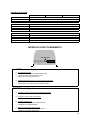
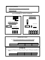
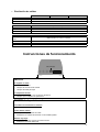
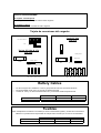
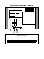
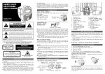
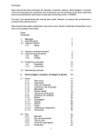
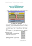
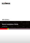
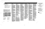
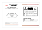
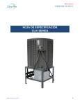
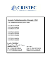
12V 10A 12V 15A 12V 20A All in One - Marine Electric Cabinet - page 2 English Version Armoires d'Energie All in One - page 8 Version française Todo en Uno - Marine Electric Cabinet - página 14 Versión Española All in One - Quadri elettrici marini - pagina 20 Versione Italiana Presented by/Presenté par/Presentado por/Presentato dalla REYA 144 Ave de la Roubine 06156 Cannes la Bocca France Tel.: 00 33 4 93 90 47 00 Fax: 00 33 4 93 90 47 10 Email: [email protected] www.reya.com Prepared 16/01/03 1 English Version Warning Before Operation The manual contains vital and essential information. The owner should read and understand this important document before operating the charger. Contact REYA if you do not understand a statement. Before Installation In order to avoid overcharging or irreversible damage to the materials, please follow closely all recommendations cited below. Do not install this system near inflammable materials. An owner should seek guidance from an authorized DOLPHIN dealer or the factory. • Do not install this system near a heat source • It should not be installed in an airtight or badly ventilated area. • All ventilation ducts must be unobstructed • Mount in a vertical position, to create natural ventilation for the charger. Note that the wiring connections are at the bottom of the charger. Leave at least three inches clearance above and below the unit for proper ventilation. • This system should not be exposed to water or dust. • It is strictly forbidden to tamper with the system casing. Connecting the Unit In order to avoid all risk of electric shock or irreversible damage to the unit, please follow very carefully the following recommendations • This unit is set to be connected to a monophase network 230V 50Hz or 115V 60Hz • On the 12V 10A and 12V 15A models, the 115V/230V selection is done by an internal switch. This manipulation must be done when the device is switched off. The position of the switch must follow the sector power supply conditions. • On the 12V 20A, 115V/230V selection is automatic. • For security reasons, the system's PE terminal must strictly be connected to the installation's Earth (green/yellow wire in the cable section) • To prevent overheating, ensure the correct connection of cables. NB: If reverse polarity of the batteries occurs, the battery fuses will automatically blow. Start up precautions • In order to prevent all risk of electric shocks at either start up or during the utilization of this system, the protection cap must rest in place and be tightly screwed. Maintenance precautions In order to prevent risk of electric shocks during maintenance, please follow closely all recommendations below before any maintenance begins. • Disconnect the cable • The access to -DC or -BAT must be disconnected in order to avoid transfer of energy. • Please wait five minutes before accessing the casing as the high-tension condensation will need time to discharge. • Fuses must be replaced by fuses that have the same characteristics and performance levels. 2 Technical Specifications Battery Charger Output voltage Output frequency Switch 115V/230V Cos φ Output Power consumed Active power Sector consumption Fuse Number of outlets Charging curve 12V 10A 12V 15A 12V 20A 230V/115V 50Hz/60Hz Selector switch 0.7 typ 230V/115V 50Hz/60Hz Selector switch 0.7 typ 80% 225W 350VA 1.5A/3A T4A 98V-264V 45Hz-65Hz Automatic 0.9 typ 150W 250VA 1A/2A T3A 2 2 I.U.Uo 3 stages 300W 350VA 3.7A-1.4A T5A 3 Boost Float Battery Voltage Max current Battery Current Charge selector "Norm" position "Pb-Ca" position DC1 boost (norm) DC1 boost (Pb-Ca) DC1 float (Norm & Pb-Ca) DC2, DC3 outlets Voltage allowance Residual waves Max charge current Fuse Short circuit fault Temp fault Reverse polarity General fault Display Configuration Operating temperature Storing temperature Humidity Electronic protection Ventilation EMC Security Battery connections All types 14.4V 13.8V DC1-0.3V +/-2% <1% 10A (+/-5%) F15A - Natural 6.35 Faston All types 14.4V 13.8V DC1-0.3V +/-2% <1% 15A (+/-5%) F20A Electronic protection Vigitherm Battery fuse protection Battery fuse protection LED On/Off 2 positions All types Calcium lead 14.4V 15.0V 13.8V DC1-0.3V +/-2% <1% 20A (+/-5%) F25A Vigitherm Flyback 50KHz & PFC (20A only) 0°C - 50°C -20°C - 70°C 10%-90% (without condensation) By tropicalization Natural Forced EN50081-1, EN50082-1, EN61000-3-2 EN60335-1 6.35 Faston Terminal screw 3 Output Distribution 12V 10A AC Connections PE Connections Protection characteristics 12V 15A By differential circuit breaker M6 bolts on the box 16A, 6.5KA, 30mA, 4 module circuit breaker Outputs Outlet connections PE Connections Protection characteristics 2 protected outputs Thermo-magnetic circuit breakers M6 bolts on the box 10A, 6.5KA, 1 module circuit breaker Box Mounting 12V 20A Painted aluminum Wall mounted - 4 x 4mm (0.1576") ∅screws 280 x 270 x 100 mm (11.03" x 10.64" x 3.94") 3kg (6.62lbs) ISO13297 Height x width x depth Weight Security Operating instructions LED "On/Off" Led OFF Non-current carrying charger • Check the presence of the line voltage • Check the adjusting input voltage • Check the main fuse Defective internal temperature (12V 15A & 20A only) • Check the installation and climatic conditions • Check the internal fan is operational ON/OFF Led is blinking Charger incorrectly connected to the battery • Check battery connection Battery fuses blown • Check the battery cables polarity • Replace the battery fuses with identical fuses Very flat batteries • Charge the battery using an external source • Replace the faulty battery 4 On/Off Led is lit Internal fan is working (12V 15A & 20A only) Charger on "BOOST" and batteries are charging Internal fan stopped Charger on "FLOAT" and batteries charged Charger Card connections Card 12V 20A Top view 115V /230V switch 115V 230V Card 12V 10A & 15A Top view Battery Fuses Motor/Aux. Battery Fuses Service Fuse Fuse Service Motor/Aux -DC +DC1 +DC2 +DC3 -DC +DC1 +DC2 +DC3 Battery Cables • • • Please ensure the correct and proper installation of all electrical connections. It is essential that +DC1 is connected to the main battery Please connect +DC2 and +DC3 to the motor battery and the auxiliary battery respectively Recommended gauge Max length 12V 10A 3mm² (0.05in²) 1.5m (4'9") 12V 15A 4mm² (0.06in²) 1.5m (4'9") 12V 20A 6mm² (0.95in²) 1.5m (4'9") Fuses Fuses should be replaced with fuses that have identical characteristics and performance levels. REYA cannot be held responsible for any damage caused where fuse types other than those recommended are used. Input gauge Battery Input 12V 10A T3A-250V F15A -32V 12V 15A T4A-250V F20A-32V 12V 20A T5A-250V F25A-32V 5 Input & Output connections PE Ventilator L1 L2 Charger card L1 L2 L1 L2 PE Input UTIL1 Output UTIL2 Output Output Cables For distribution output, we recommend you use a HO7RNF cable. Recommended gauge Max length 12V 10A 3 x 1.5mm² (0.023in²) 5m (16.5') 12V 15A 3 x 1.5mm² (0.023in²) 5m (16.5') 12V 20A 3 x 2.5mm² (0.023in²) 5m (16.5') 6 Warranty In order to avoid all risk arising from the incorrect use of this device, please carefully read the list of possible situations or faults that are not covered by the warranty. • This device is not protected against reverse battery polarity. Irreversible damage may result. • If the mechanical components of the device are not protected by the casing and fall, irreversible damage of the ventilation system and certain electrical components may result. • Modifications made to the casing (and in particular if holes are bored), may result in the deposit of metallic shavings or filings onto the electronic card and consequently may cause the malfunction of or damage to the device. • Interfering with or modifications made to the electronic card may result in unforeseen operations and consequently may cause the malfunction of or damage to the device. • Use of a non-adapted power supply (as a general rule, the input voltage will be too high) may cause the malfunction of or damage to the device. • An accidental electrical surcharge or lightening strike will generally cause the malfunction of or damage to the device. • Replacement of battery fuses with fuse types other than those recommended (same characteristics) may cause the malfunction of or damage to the device. • Obvious connection errors will result in the malfunction of or damage to the device. • Water gaining access to the interior of the device may cause the malfunction of or damage to the device. 7 Version française PRECAUTIONS DE SECURITE !! AFIN DE PREVENIR TOUT RISQUE DE CHOC ELECTRIQUE OU D’INCENDIE, LIRE ATTENTIVEMENT CE MANUEL AVANT D’INSTALLER L’APPAREIL - Cet appareil contient des composants qui peuvent provoquer des arcs électriques ou étincelles, lors des raccordements par exemple. Afin de prévenir tout risque d’incendie ou d’explosion, ne pas installer cet appareil à proximité de matériels, liquides ou gaz inflammables PRECAUTIONS D’INSTALLATION - Afin de prévenir tout risque de surchauffe ou de dommage irréversible sur le matériel, veillez à suivre de manière impérative et rigoureuse les recommandations ci-dessous : .Cet appareil ne doit pas être installé à proximité d’une source de chaleur .Il ne doit pas être installé dans un compartiment étanche ou mal aéré .Les ouies de ventilations ne doivent pas être obstruées .Un espace libre d’au moins 10cm doit être prévu tout autour du coffret pour permettre une bonne convection .Cet appareil ne doit pas être exposé aux ruissellements, aux projections d’eau et aux poussières de toutes natures .Il est recommandé de fixer l’appareil en position verticale, la sortie des câbles orientée vers le bas .Il est formellement interdit de modifier mécaniquement le coffret par des perçages supplémentaires par exemple PRECAUTIONS DE RACCORDEMENTS - Afin de prévenir tout risque de choc électrique ou de dommage irréversible sur le matériel, veillez à suivre de manière impérative les recommandations ci-dessous : .Cet appareil est prévu pour être raccordé sur des réseaux monophasés 230V 50Hz ou 115V 60Hz .Sur les modèles 12V 10A et 12V 15A, la sélection 115V / 230V s’effectue par commutation du strap interne. Cette manœuvre doit impérativement s’effectuer hors tension. La position du strap doit suivre de manière rigoureuse les conditions d’alimentation secteur .Sur le modèle 12V 20A, la sélection 115V / 230V est automatique .Pour des raisons de sécurité, la borne PE de cet appareil doit impérativement être raccordée à la terre générale de l’installation (fil vert / jaune du câble secteur) .Pour prévenir tout échauffement parasite, veiller à la bonne section des câbles ainsi qu’aux bons serrages des connections - IMPORTANT : Une inversion de polarité côté batteries entraîne automatiquement la rupture des fusibles batteries PRECAUTIONS DE MISE EN SERVICE - Afin de prévenir tout risque de choc électrique lors de la mise en service ou pendant le fonctionnement, le capot de protection doit impérativement être en place et correctement vissé sur le bâti PRECAUTIONS DE MAINTENANCE - Afin de prévenir tout risque de choc électrique lors des opérations de maintenance, veillez à suivre de manière impérative les recommandations qui suivent avant d’intervenir dans l’appareil : .L’accès secteur doit impérativement être déconnecté (câble ou sectionneur) .L’accès –DC ou -BAT doit lui aussi être déconnecté pour éviter tout transfert d’énergie .Pour permettre aux condensateurs haute tension de se décharger, attendre 5 minutes avant d’intervenir dans le coffret .Les fusibles doivent être remplacés par des fusibles aux caractéristiques et performances strictement identiques 8 SPECIFICATIONS TECHNIQUES CHARGEUR DE BATTERIES Tension secteur Fréquence secteur Commutation 115V / 230V Cos φ Rendement Puissance consommée Puissance active Consommation secteur Fusible secteur Nombre de sorties Courbe de charge 12V 10A 12V 15A 12V 20A 230V/115V 50Hz/60Hz Sélecteur 0.7 typ 230V/115V 50Hz/60Hz Sélecteur 0.7 typ 80% 225W 350VA 1.5A/3A T4A 98V-264V 45Hz-65Hz Automatique 0.9 typ 150W 250VA 1A/2A T3A 2 300W 350VA 3.7A-1.4A T5A 2 I.U.Uo 3 stages 3 Boost Float Max current Sélecteur de charge Position « Norm » Position Pb-Ca DC1 boost (norm) DC1 boost (Pb-Ca) DC1 float (Norm & Pb-Ca) Sorties DC2, DC3 Tolérance tensions Ondulation résiduelle Courant max. de charge Fusibles de sorties Tous types 14.4V 13.8V DC1-0.3V +/-2% <1% 10A (+/-5%) F15A Défaut court-circuit Défaut température Inversion de polarité Défaut général Visualisation Protection électronique Vigitherm Vigitherm Protection par fusible batterie Protection par fusible batterie Led verte « Chargeur ON » Voyant orange « Secteur présent » Flyback 50KHz & PFC (20A uniquement) 0°C - 50°C -20°C - 70°C 10%-90% (sans condensation) Par tropicalisation Naturelle Forcée Forcée EN50081-1, EN50082-1, EN61000-3-2 EN60335-1 6.35 Faston 6.35 Faston Terminal screw Topologie Climatique Stockage Humidité Protection électronique Convection CEM Sécurité Raccordements batteries Tous types 14.4V 13.8V DC1-0.3V +/-2% <1% 15A (+/-5%) F20A 2 positions Tous types Plomb Calcium 14.4V 15.0V 13.8V DC1-0.3V +/-2% <1% 20A (+/-5%) F25A - 9 DISTRIBUTION SECTEUR Raccordements secteur Raccordement PE Caractéristiques protection 12V 10A 12V 15A Sur disjoncteur différentiel Goujon M6 sur coffret Disjoncteur 16A, 6,5KA, 30mA, 4 modules Sorties utilisation Raccordements sorties Raccordements PE Caractéristiques protection 2 sorties protégées Sur disjoncteur magnétothermique Goujon M6 sur coffret Disjoncteur 10A, 6,5KA, 1 module Coffret Fixation Haut. x larg. x prof. Poids Sécurité 12V 20A En aluminium peint Murale par 4 ∅ 4mm 280 x 270 x 100 mm 3kg ISO13297 MODES DE FONCTIONNEMENTS LED "On/Off" Led OFF ⇒ ⇒ ⇒ Armoire hors tension Vérifier l’état du disjoncteur différentiel principal Vérifier la présence de la tension secteur Vérifier les raccordements secteur ⇒ ⇒ Défaut température interne (12V 15A & 20A uniquement) Vérifier les conditions d’installation et climatiques Vérifier le bon fonctionnement du ventilateur interne ON/OFF Led clignote ⇒ Chargeur à vide ou raccordé à des batteries chargées Chargeur en stand-by (fonctionnement normal) ⇒ Chargeur mal raccordé côté batteries Vérifier les raccordements batteries ⇒ ⇒ Fusibles batteries H.S. Vérifier la bonne polarité des câbles batteries Remplacer les fusibles batteries ⇒ ⇒ Batteries en décharge très profonde Démarrer la recharge par un moyen externe Remplacer la batterie défectueuse 10 On/Off Led est allumée ⇒ Ventilateur interne en fonctionnement (12V 15A & 20A uniquement) Chargeur en BOOST et batteries en cours de recharge Ventilateur interne arrêté Chargeur en FLOAT et batteries chargées • RACCORDEMENTS CARTE CHARGEUR CARTE 12V 20A VUE DE DESSUS Selecteur 115V /230V 115V 230V CARTE 12V 10A & 15A VUE DE DESSUS Fusible batteries Motor/Aux. Fusible batteries Fuse Fuse Service Service Motor/Aux. -DC +DC1 +DC2 +DC3 -DC +DC1 +DC2 +DC3 CABLES BATTERIE Veillez à la qualité des raccordements et au bon serrage des connections L’accès +DC1 doit impérativement être raccordé à la batterie principale Les accès +DC2 et +DC3 servent aux batteries moteur et auxiliaire Section préconisée Longeur Max. 12V 10A 3mm² 1.5m 12V 15A 4mm² 1.5m 12V 20A 6mm² 1.5m FUSIBLES En cas de maintenance des fusibles, ceux-ci doivent être remplacés par des fusibles aux caractéristiques et performances strictement identiques. Risques de dommages irréversibles sur le matériel Input gauge Battery Input 12V 10A T3A-250V F15A -32V 12V 15A T4A-250V F20A-32V 12V 20A T5A-250V F25A-32V 11 RACCORDEMENTS SECTEUR & UTILISATIONS PE Ventilator L1 L2 Carte de chargeur L1 L2 L1 L2 PE Input UTIL1 Output UTIL2 Output CABLES SECTEUR Pour la distribution secteur, utiliser de préférence du câble de type HO7RNF Section préconisée Longueur max 12V 10A 3 x 1.5mm² 5m 12V 15A 3 x 1.5mm² 5m 12V 20A 3 x 2.5mm² 5m 12 GARANTIE AFIN DE PREVENIR TOUT RISQUE DE MAUVAISE UTILISATION DE L’APPAREIL, LIRE ATTENTIVEMENT LA LISTE DES EVENEMENTS OU DEFAUTS POTENTIELS NON COUVERTS PAR LA GARANTIE PRODUIT - Chute mécanique de l’appareil non emballé pouvant entraîner des déformations irréversibles du coffret ainsi que le « crash » du ventilateur interne et de certains composants électroniques - Modifications du coffret (perçages additionnels en particulier) pouvant entraîner la diffusion de copeaux ou de limailles métalliques sur la carte électronique et par voie de conséquence, des dysfonctionnements ou dégâts irréversibles sur le matériel - Interventions ou modifications sur la carte électronique pouvant entraîner des modes de fonctionnements non prévus à l’origine, et par voie de conséquence, des dysfonctionnements ou dégâts irréversibles sur le matériel - Alimentation de l’ensemble par une source non adaptée (en règle générale, tension d’alimentation secteur trop haute) pouvant entraîner des dégâts irréversibles sur le matériel - Surtension secteur d’origine accidentelle ou choc foudre entraînant en règle générale des dégâts irréversibles sur le matériel - Remplacement des fusibles batterie (en cas d’inversion de polarités par exemple) ou secteur par des fusibles aux caractéristiques différentes pouvant entraîner des dégâts irréversibles sur le matériel - Erreurs manifestes de raccordements entraînant des dégâts irréversibles sur le matériel • - Projections ou ruissellements d’eau à l’intérieur de l’appareil pouvant entraîner des dysfonctionnements irréversibles sur le plan électronique 13 Versión Española Advertencias Antes del Funcionamiento El manual contiene la información vital y esencial. El dueño debe leer y debe entender este documento importante antes de operar el cargador. Avise a IMNASA si usted no entiende una declaración. Antes de la Instalación Para evitar sobrecargar o daño irreversible a los materiales, por favor siga todas las recomendaciones citadas debajo estrechamente. No instale este sistema cerca de los materiales inflamables. Un dueño debe buscar la guía de distribuidores de DOLFÍN autorizado o la fábrica. • No instale este sistema cerca de una fuente de calor • No debe instalarse en una zona hermética o mal ventilada. • Todos los conductos de ventilación deben ser los homologados. • Monte en una posición vertical, crear una ventilación natural para el cargador. Las conexiones de la instalación eléctrica están en la parte baja del cargador. Deje ocho centímetros de margen por encima y debajo de la unidad para una ventilación apropiada. • Este sistema no debe exponerse al agua o al polvo. • Esta prohibido manipular o tocar el interior de la caja. • Conexión de la Unidad Para evitar todo el riesgo de choque eléctrico o daño irreversible a la unidad, por favor siga las recomendaciones siguientes muy cuidadosamente • Esta unidad está preparada para ser conectada a una línea monofásica, red 230V 50Hz o 115V 60Hz • En los nodelos de 12V 10A y 12V 15A, la selección de entrada 115V/230V se hace mediante un interruptor interior. Esta manipulación debe hacerse cuando el dispositivo se apaga. La posición del interruptor debe seguir las condiciones de suminitro. • En los equipo 12V 20A, 115V/230V el selector es automático. • Por razones de seguridad, el término de PE del sistema debe conectarse a Tierra de la instalación (los colores verde/amarillo muestran la selección del cable) • Para prevenir temperatura, asegure la conexión correcta de los cables. NB: Si se produce polaridad inversa en la conexión de las baterías, los fusibles de la batería saltarán automáticamente. Utilice las precauciones necesarias • Para prevenir todo el riesgo de cruces eléctricos a cualquier salida o durante la utilización de este sistema, la funda de protección debe colocarse en su lugar y debe quedar atornillado herméticamente. Precauciones de mantenimiento Para prevenir riesgo de cruces eléctricos durante el mantenimiento, por favor siga todas las recomendaciones abajo indicadas antes de empezar cualquier mantenimiento. • Desconecte el cable de alimentación • El acceso - DC o - el borne debe ser desconectado para evitar fuga de energía. • Por favor espere cinco minutos antes de acceder a la carcasa puesto que la condensación de alta tensión necesitará tiempo para descargar. • Los fusibles deben ser reemplazados por fusibles con las mismas características y niveles del funcionamiento 14 Especificaciones técnicas 1. Cargador Batería Voltaje entrada Frecuencia salida Conexión 115V/230V Cos Salida Consumo Potencia activa Consumo del sector Fusible Numero de salidas Curva de carga 12V 10A 12V 15A 12V 20A 230V/115V 50Hz/60Hz Selector switch 0.7 typ 230V/115V 50Hz/60Hz Selector switch 0.7 typ 80% 225W 350VA 1.5A/3A T4A 98V-264V 45Hz-65Hz Automatic 0.9 typ 150W 250VA 1A/2A T3A 2 2 I.U.Uo 3 stages 300W 350VA 3.7A-1.4A T5A 3 Boost Float Battery Voltage Max current Battery Current Selector de carga Posición "Norm" Posición "Pb-Ca" DC1 boost (norm) DC1 boost (Pb-Ca) DC1 float (Norm & Pb-Ca) DC2, DC3 tomas Entrega de voltaje Picos residuales Carga Máxima Fusible Corto circuito Subida Temperatura Inversión polaridad Inversión polaridad Pantalla Configuración Temperatura trabajo Temperatura guardado Humedad Protección electrónica Ventilación EMC Seguridad Conexiones batería All types 14.4V 13.8V DC1-0.3V +/-2% <1% 10A (+/-5%) F15A - Natural 6.35 Faston All types 14.4V 13.8V DC1-0.3V +/-2% <1% 15A (+/-5%) F20A Electronic protection Vigitherm Battery fuse protection Battery fuse protection LED On/Off 2 positions All types Calcium lead 14.4V 15.0V 13.8V DC1-0.3V +/-2% <1% 20A (+/-5%) F25A Vigitherm Flyback 50KHz & PFC (20A only) 0°C - 50°C -20°C - 70°C 10%-90% (without condensation) By tropicalization Natural Forced EN50081-1, EN50082-1, EN61000-3-2 EN60335-1 6.35 Faston Terminal screw 15 2. Distribución de salidas 12V 10A AC Conexiones PE Conexiones Protección caracteristicas 12V 15A By differential circuit breaker M6 bolts on the box 16A, 6.5KA, 30mA, 4 module circuit breaker Salidas Conexiones de salida PE Conexiones Protección caracteristicas 2 protected outputs Thermo-magnetic circuit breakers M6 bolts on the box 10A, 6.5KA, 1 module circuit breaker Montaje altura x profundidad x ancho Peso Montaje Seguridad 12V 20A Painted aluminum Wall mounted - 4 x 4mm ∅screws 280 x 270 x 100 mm 3kg ISO13297 Instrucciones de funcionamiento LED "On/Off" Led OFF El cargador no actúa • Verifique la corriente • Verifique la conexión de la entrada • Verifique el fusible principal La temperatura interior • Verifique la instalación y las condiciones climáticas • Verifique que el cargador es operacional ON/OFF Led pestañeando Conectado incorrectamente a la batería • Verifique la conexión de la batería Fusible batería saltado • Compruebe la polaridad de los cable • Reemplace los fusibles de la batería con los fusibles iguales Baterías muy bajas • Cargue la batería que usando una fuente externa • Reemplace la batería defectuosa 16 On/Off Led enciende El cargador está trabajando • El cargador en "BOOST" y las baterías están cargando El cargador se detuvo El cargador en "FLOAT" las baterías están cargadas Tarjeta de conexiones del cargador Card 12V 20A Top view 115V /230V switch 115V 230V Tarjeta 12V 10A & 15A Top view Battery Fuses Motor/Aux. Battery Fuses Fusible Fuse Service Service Motor/Aux. -DC +DC1 +DC2 +DC3 -DC +DC1 +DC2 +DC3 Battery Cables • • • Por favor asegure de la instalación correcta y apropiada de todas las conexiones eléctricas.. Es imprescindible que el +DC1 se conecte a la batería princepal Conecte el +DC2 y el +DC3 a la bateria del motor y a la bateria auxiliar respectivamente Entrada Cables Max longitud 12V 10A 3mm² 1.5m 12V 15A 4mm² 1.5m 12V 20A 6mm² 1.5m Fusibles Deben reemplazarse los fusibles con fusibles que tienen características iguales y niveles de funcionamiento. IMNASA no puede hacerse responsable de cualquier daño causado por no usar los recomendados. Medición de entrada Entrada batería 12V 10A T3A-250V F15A -32V 12V 15A T4A-250V F20A-32V 12V 20A T5A-250V F25A-32V 17 Conexiones de entrada y salida PE Ventilador L1 L2 Charger card L1 L2 L1 L2 PE Input UTIL1 Output UTIL2 Output Salida Cables Para la distribución de salida, le recomendamos que use cable HO7RNF. Medida recomendada Largo máximo 12V 10A 3 x 1.5mm² 5m 12V 15A 3 x 1.5mm² 5m 12V 20A 3 x 2.5mm² 5m 18 Garantía Para evitar todo el riesgo producido por un uso incorrecto de este dispositivo, recomendamos que lean cuidadosamente la lista de posibles situaciones o fallos que no se cubren por la garantía. • Este dispositivo no está protegido contra la inversión de polaridad de la batería. Puede provocarse un daño irreversible. • Si los componentes mecánicos del dispositivo no están protegidos por la caja, o se estropea el sistema de ventilación, ciertos componentes eléctricos puede resultar dañados. • Las modificaciones efectuadas en la carcasa (y en particular si los orificios están agrandados), puede producir que la viruta metálicas o limaduras se depositen encima de la tarjeta electrónica y por consiguiente puede causar el funcionamiento defectuoso o puede dañar el dispositivo. • Las modificaciones en la tarjeta electrónica puede provocar funcionamientos imprevistos y por consiguiente pueden causar el funcionamiento defectuoso o dañar el cargador. • El uso de un equipo no preparado a una condiciones Ej. (Voltaje de entrada demasiado alto) puede causar el funcionamiento defectuoso o puede dañar al cargador. • Una sobrecarga eléctrica accidental o la bajada de la tensión o oscilaciones producidas por tormentas o obras próximas pueden provocar el funcionamiento defectuoso o dañarán el cargador. • El cambio de fusibles de la batería con tipos del fusible de otra manera que aquéllos recomendados ( mismas características) puede causar el funcionamiento defectuoso de o puede dañar al cargador. • Los errores de conexión obvios producirán el funcionamiento defectuoso de o dañarán al cargador. • La entrada de Agua al interior del contenedor puede causar el funcionamiento defectuoso o puede dañar al cargador. 19 Versione Italiana Avvertenze Prima dell’impiego Questo manuale contiene informazioni essenziali e di vitale importanza. Prima di impiegare il carica batterie è necessario leggere completamente e comprendere il contenuto di questo manuale. Nel caso non si comprendesse un concetto non esitare a contattare la REYA. Prima dell’installazione Al fine di evitare sovraccarichi o danni irreversibili all’apparecchiatura, si invita a seguire alla lettera le raccomandazioni che seguono. Non installare questo apparato nei pressi di materiale infiammabile. Il proprietario potrà richiedere l’assistenza del concessionario della DOLPHIN o direttamente allo stabilimento. • • • • • • Non installare questo apparato nei pressi di fonti di calore. Non dovrà neppure essere installato in ambienti chiusi o mal ventilati. Non ostruire le aperture di ventilazione. Montarlo in posizione verticale, in modo da creare all’interno del ventilatore una ventilazione naturale. Si tenga conto che i collegamenti dei cavi sono nella parte inferiore del carica batterie. Per assicurare l’opportuna ventilazione lasciare uno spazio minimo di 7-8 cm sopra e sotto l’apparato. Questo apparato non va esposto all’acqua e alla polvere. È assolutamente proibito manomettere la custodia dell’apparato. Collegamento dell’apparato Per evitare qualsiasi rischio di scossa elettrica o eventuali danni all’apparato, si invita a seguire scrupolosamente le raccomandazioni che seguono: • Questo apparato è adatto ad essere collegato o alla rete elettrica monofase da 230 V 50 Hz o a quella a 115 V 60 Hz. • Sui modelli 12V 10A e 12V 15A, la commutazione 115V/230V viene attuata con un interruttore interno. Eseguire questa commutazione solamente con l’apparato spento. La posizione del commutatore dovrà essere conforme alle condizioni di fornitura della rete elettrica. • Sul modello 12V 20A, 115V/230V la commutazione è automatica. • Per motivi di sicurezza, il terminale PE dell’apparato dovrà essere tassativamente collegato alla massa dell’impianto (filo giallo/verde del cavo di alimentazione) • Per prevenire surriscaldamenti, eseguire il collegamento dei cavi in modo corretto. NB: Nel caso si collegassero le batterie con la polarità invertita, si bruceranno gli specifici fusibili di protezione. Precauzioni di avviamento • Al fine di evitare ogni rischio di scossa elettrica sia all’avviamento sia durante il normale utilizzo di questo apparato, il tappo di protezione dovrà restare al suo posto e avvitato a fondo. Manutenzione preventiva Al fine di evitare ogni rischio di scossa elettrica durante la manutenzione, attenersi scrupolosamente alle raccomandazioni che prima di intraprendere qualsiasi azione di manutenzione. • Staccare il cavo • Per evitare eventuali trasferimenti di energia staccare l’accesso a -DC o a -BAT. • Si invita ad attendere cinque minuti prima di accedere all’interno della custodia, i condensatori ad alta tensione richiedono tempo per scaricarsi. • Sostituire i fusibili eventualmente bruciati con altri dalle identiche caratteristiche. 20 Specifiche tecniche Carica batterie Tensione di entrata Frequenza di entrata commutazione115V/230V Cos φ Uscita Potenza consumata Potenza attiva Assorbimento di rete Fusibile Numero di uscite Curva di carica 12V 10A 12V 15A 12V 20A 230V/115V 50Hz/60Hz commutatore 0.7 tipico 230V/115V 50Hz/60Hz commutatore 0.7 tipico 80% 225W 350VA 1.5A/3A T4A 98V-264V 45Hz-65Hz automatica 0.9 tipico 2 I.U.Uo 3 stadi 3 150W 250VA 1A/2A T3A 2 300W 350VA 3.7A-1.4A T5A Carica rapida livellata Tensione batteria Corrente massima Corrente batteria Selettore di carica Posizione "Norm" Posizione "Pb-Ca" CC1 boost (norm) CC1 boost (Pb-Ca) CC1 float (Norm & Pb-Ca) Uscite CC2, CC3 Tolleranza di tensione Onde residue Massima corrente di carica Fusibile Protezione cortocircuito Protezione temperatura Inversione di polarità Guasto generale Visualizzazione Configurazione Temperatura d’esercizio Temperatura magazzino Umidità Protezione elettronica Ventilazione EMC Sicurezza Collegamento batteria Tutti i tipi 14.4V 13.8V CC1-0.3V +/-2% <1% 10A (+/-5%) F15A - Naturale 6.35 Faston Tutti i tipi 14.4V 13.8V CC1-0.3V +/-2% <1% 15A (+/-5%) F20A 2 posizioni Tutti i tipi Calcio piombo 14.4V 15.0V 13.8V CC1-0.3V +/-2% <1% 20A (+/-5%) F25A Protezione elettronica Vigitherm Vigitherm Fusibile protezione batteria Fusibile protezione batteria a LED On/Off Flyback 50KHz & PFC (solamente 20A) 0°C - 50°C -20°C - 70°C 10%-90% (senza condensa) Per tropicalizzazione Naturale Forzata EN50081-1, EN50082-1, EN61000-3-2 EN60335-1 6.35 Faston Morsetto a vite 21 Distribuzione uscite 12V 10A Collegamenti CA Collegamenti PE Caratteristiche protezione 12V 15A Con interruttore differenziale Bulloni M6 all’interno della custodia 16A, 6.5KA, 30mA, circuit breaker modulo 4 Uscite Connessioni uscite Connessioni PE Caratteristiche protezione 2 uscite protette Interruttori magneto-termici Bulloni M6 all’interno della custodia 10A, 6.5KA, circuit breaker modulo 1 Custodia Montaggio 12V 20A Alluminio verniciato A parete – viti da ∅ 4 x 4mm ∅ 280 x 270 x 100 mm 3kg ISO13297 Alto x largo x profondo Peso Sicurezza Istruzioni d’uso LED "On/Off" Led spento Carica batterie non alimentato • Verificare l’alimentazione • Verificare il collegamento di ingresso • Verificare il fusibile principale Temperatura interna troppo alta (solamente 12V 15A e 20A) • Verificare l’installazione e controllare le condizioni climatiche • Verificare che la ventola interna funzioni Led lampeggiante Carica batterie collegato alla batteria in modo errato • Verificare i collegamenti alla batteria Fusibile della batteria bruciato • Verificare la polarità dei cavi della batteria • Sostituire i fusibili delle batterie con altri identici Batterie molto scariche • Caricare la batteria con una fonte esterna • Sostituire la batteria difettosa 22 Led acceso Ventola interna in funzione • Carica batterie su "BOOST" e batterie sotto carica Ventola interna ferma Carica batterie su "FLOAT" e batterie sotto carica Collegamenti della scheda del carica batterie Scheda 12V 20A Vista dall’alto Commutatore 115V /230V 115V 230V Scheda 12V 10A e 15A vista dall’alto Fusibili batterie Motore/Aux Fusibili batterie Fusibile Servizio Servizio Fusibile Motore/Aux. -DC +DC1 +DC2 +DC3 -DC +DC1 +DC2 +DC3 Cavi batterie • • • Verificare l’esatto collegamento di tutte le connessioni elettriche. È fondamentale che il cavo + DC1 sia collegato alla batteria principale Collegare i cavi +DC2 e +DC3 rispettivamente alla batteria del motore e a quella ausiliaria Sezione raccomandata Lunghezza massima 12V 10A 3mm² 1.5m 12V 15A 4mm² 1.5m 12V 20A 6mm² 1.5m Fusibili Sostituire i fusibili bruciati con altri con le stesse caratteristiche. La REYA non si riterrà responsabile di eventuali danni causati dall’uso di fusibili diversi da quelli raccomandati. Sezione di entrata Entrata batteria 12V 10A T3A-250V F15A -32V 12V 15A T4A-250V F20A-32V 12V 20A T5A-250V F25A-32V 23 Collegamenti di entrata e di uscita PE Ventilatore L1 L2 Scheda carica batterie L1 L2 L1 L2 PE Entrata Uscita UTIL1 Uscita UTIL2 Cavi di uscita Per la distribuzione delle uscite si raccomanda di usare cavo HO7RNF. Sezione raccomandata Lunghezza massima 12V 10A 3 x 1.5mm² 5m 12V 15A 3 x 1.5mm² 5m 12V 20A 3 x 2.5mm² 5m 24 Garanzia Al fine di evitare ogni eventuale rischio dovuto all’uso improprio di questo dispositivo, si prega di leggere attentamente l’elenco delle possibili situazioni o guasti non coperti dalla garanzia. • Questo apparato non è protetto contro l’inversione della polarità della batteria. Si potrebbero verificare danni irreparabili. • Se i componenti meccanici del dispositivo non sono protetti dalla custodia e dalle cadute, si potrebbero verificare danni irreparabili al sistema di ventilazione ed ad alcuni componenti elettrici. • Le modifiche alla custodia (e in particolare se si praticano dei fori), potrebbero causare depositi di segatura o trucioli metallici sulla scheda elettronica con conseguente malfunzionamento o guasto del dispositivo. • La manomissione o la modifica della scheda elettronica potrebbe provocare funzionamenti imprevisti con conseguenti malfunzionamenti o guasti del dispositivo. • L’uso di una fonte di alimentazione inadatta (come regola generale, la tensione d’entrata troppo alta) può provocare malfunzionamenti e guasti al dispositivo. • Un sovraccarico elettrico accidentale o il fulmine provocano normalmente il malfunzionamento e il danneggiamento del dispositivo. • La sostituzione dei fusibili della batteria con altri di tipo diverso da quelli raccomandati (stesse caratteristiche) può provocare malfunzionamenti e guasti al dispositivo. • Gli errori di collegamento ovviamente possono provocare malfunzionamenti e guasti al dispositivo. • L’acqua eventualmente entrata all’interno della custodia può provocare malfunzionamenti e guasti al dispositivo. 25