1
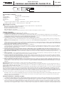
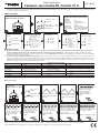
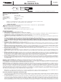
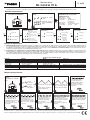
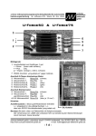
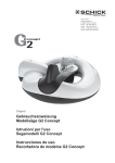
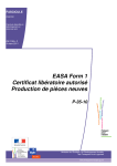
Bedienungsanleitung BL Control 70 A No. 8649 Anschlußschema und Technische Daten: Motor rot + rot blau Regler schwarz - schwarz Akku Empfänger Zur Drehrichtungsumkehr zwei Motorkabel vertauschen Bedienungsanleitung BL Control 70 A Technische Daten Typ Eingangsspannung: Dauerstrom: Kurzz. Strom: Abmessungen: Gewicht: - - - - - - - - BL Control 70 A 5,5 - 25,2 V (2 - 6 Zellen Lithium) 70 A 110 A (5 sec.) ca. 65 x 28 x 15,5 mm ca. 64 g Geeignet für folgende Motortypen: 2- bis 10-polig, Innenläufer / Aussenläufer Drehzahlbegrenzungen: 2-polig - 190 000 U/ Min.; 6-polig - 63000 U/ Min. ! Sicherheitshinweise Bei Inbetriebnahme nie in den Drehkreis der Luftschraube / Rotorblätter geraten - Verletzungsgefahr. Beachten Sie die technischen Daten des Reglers. Polung aller Anschlusskabel beachten. Auf richtige Polung der Motoranschlusskabel achten Kurzschlüsse unbedingt vermeiden Den Regler so einbauen bzw. verpacken, daß er nicht mit Fett, Öl oder Wasser in Berührung kommen kann. Besondere Eigenschaften 1. Bremse - 3 Einstellungen: Bremse ausgeschaltet / sanfte Bremse / harte Bremse 2. Elektronisches Timing - 3 Einstellungen: Niedriges Timing / mittleres Timing / hohes Timing. Grundsätzlich empfehlen wir niedriges Timing für 2-polige Motoren, mittleres Timing für 6-polige (bzw. mehr) Motoren. Hohes Timing ergibt mehr Leistung, jedoch bei niedrigerem Wirkungsgrad. Um eine Überlastung des Akkus zu vermeiden, ist es wichtig, nach einem Timing-Wechsel den Betriebsstrom zu prüfen. 3. Unterspannungsabschaltung - 2 Einstellungen: mittlere und hohe Entladespannung. Die Werkseinstellung ist “hohe Entladespannung”; sie vermeidet eine übermäßige Entladung des Akkus. Folgende Werte pro Zelle werden eingestellt: A: Hohe Entladespannung: 1. Stufe 3,2 V,; 2. Stufe 3,0 V. B: Mittlere Entladespannung: 1. Stufe 3,0 V,; 2. Stufe 2,8 V. Fällt die Spannung auf den ersten Wert, schaltet der Regler auf Akku-Schonung um; d.h. die Leistung wird reduziert; die Landung sollte umgehend eingeleitet werden, bei Abfall der Spannung auf den zweiten Wert schaltet der Regler ab (nur im Modus “Flächenmodelle/Segler). HINWEIS: DIESE EINSTELLUNG EIGNET SICH AUSSCHLIESSLICH FUR VOLLGELADENE AKKUS IN GUTEM ZUSTAND. 4. Flugmodellmodus - 3 Einstellungen: Flächenmodell / Hubschrauber 1 / Hubschrauber 2. Der Flächenmodellmodus eignet sich für Flugmodelle bzw. E-Segler. Wenn Sie einen Hubschrauber einsetzen wollen, können Sie zwischen Helicopter 1 bzw. Helicopter 2 wählen: bei Helicopter 1 steht die Funktion Soft-Start (sanfter Anlauf) zur Verfügung; bei Helicopter 2 sowohl Soft-Start als auch Drehzahlregelung. 5. Anpassung der Reaktionsgeschwindigkeit des Gasknüppels: Der Regler besitzt 3 Einstellmöglichkeiten der Reaktionsgeschwindigkeit: Standard, Medium und Quick. Damit ist eine Anpassung an das gewünschte Flugverhalten möglich. Werksseitig ist “Standard” eingestellt. Bei Einstellung “Medium” oder “Quick” für Kunstflug oder 3D spricht der Motor schneller an. Leistung und Spitzenströme steigen. 6. Einstellung der BEC-Spannung: Werksseitig ist die BEC-Spannung auf 5,5 V eingestellt. Falls die eingebauten Servos dies erfordern, kann die BECSpannung auf 5,0 V bzw. 6,0 V geändert werden. 7. Thermischer Schutz: Steigt die Temperatur des Reglers auf 80°C, wird eine Schonfunktion eingeschaltet; d.h. die Leistung wird reduziert. Der Regler sollte auf jeden Fall immer so eingebaut werden, dass er vom Fahrtwind gut gekühlt wird. 8.Sicherheits-Einschaltschutz: Der Regler erkennt das Senderausgangssignal, sobald er eingeschaltet wird. Dabei gibt er einen Bestätigungston aus und schaltet in Normalmodus, wenn der Gasknüppel auf Leerlauf steht. Steht der Gasknüppel auf “Vollgas”, schaltet der Regler in den Einstellmodus. Steht der Gasknüppel in einer anderen Position, ertönt reglerseitig ein Alarmton. Dabei schaltet er sicherheitshalber nicht in den normalen Betriebsmodus, um ein ungewolltes Anlaufen des Motors zu verhindern. 9.Flugmodell-Ortungspiepser: Führt das Flugmodell eine Aussenlandung durch, kann der Pilot den Flugmodell-Ortungs-Modus einschalten. Diese Funktion wird durch Ausschalten des Senders aktiviert. Sobald der Regler 30 Sekunden lang keinen Sendersignal empfängt, gibt er einen Alarmton durch den Motor aus. Der Zweck des Alarmtons ist es, dem Piloten zu helfen das Modell wieder aufzufinden. Der Ortungspiepser funktioniert nicht mit einem PCM-Empfänger. Zu 4. Flächenmodell- / Segler-Modus: Dieser Modus bezieht sich auf herkömmliche Flächenmodelle bzw. Segelflugmodelle. Hubschraubermodus 1: In diesem Modus steht ein Soft-Start (sanfter Anlauf) zur Verfügung; er bezieht sich auf Hubschrauber-Modelle fur die Betriebsarten Normal, Gas-Vorwahl 1 bzw. Gas-Vorwahl 2. Bitte beachten Sie: In den Betriebsarten Gas-Vorwahl 1 bzw. Gas-Vorwahl 2 sollte die Empfindlichkeit des Gyros niedriger eingestellt werden, falls das Heck wegen der höheren Drehzahl nicht ruhig bleibt (pendelt). Hubschraubermodus 2: In diesem Modus stehen sowohl ein Soft-Start (sanfter Anlauf) als auch eine Drehzahlregelung zur Verfügung; er bezieht sich auf Hubschrauber-Modelle für die Betriebsarten Gas-Vorwahl 1 bzw. Gas-Vorwahl 2 (für die Betriebsart Normal nicht geeignet). In der Betriebsart Drehzahlregelung sollte der Gaswert im Bereich 85% bis 100% bleiben. Wenn das Heck nicht ruhig bleibt (wie oben beschrieben), sollte die Empfindlichkeit des Gyros soweit reduziert werden, bis das Wackeln aufhört. Die Drehzahlregelung funktioniert unter Umständen nicht, wenn die Rotordrehzahl wegen falscher Untersetzung zu niedrig ist, wenn der Akku nicht hochstromfähig ist, wenn die Empfindlichkeit des Gyros nicht richtig eingestellt wurde, wenn der Anstellwinkel der Hauptrotorblätter nicht richtig ist, usw. Bitte stellen Sie sicher, dass alle Parameter korrekt eingestellt sind, bevor Sie versuchen, die Funktion Drehzahlregelung einzusetzen. - Softanlauf: Nach Anschluss des Flugakkus reagiert der Regler im Hubschraubermodus nur das erste Mal mit Softanlauf. Ansonsten läuft der Motor nach Abstellen und erneutem Gas geben sofort wieder hoch. Erst wenn der Motor 30 Sekunden ausgeschaltet war, ist der Softanlauf wieder aktiviert. Wichtige Hinweise: Drehzahlregelung: 1. Die Drehzahlregelung hält die Drehzahl des Hauptrotors konstant, jedoch nur bei genügend hoher Rotordrehzahl (wir empfehlen 85% bis 100%). Eine niedrige Rotordrehzahl benötigt einen sehr hohen Anstellwinkel der Rotorblätter, was einen hohen Strom mit sich bringt, wobei der Motor überlastet wird. 2. Bei voreingestellter Hauptrotordrehzahl wird die Rotordrehzahl im Drehzahlregler-Modus automatisch konstant gehalten. Bitte beachten Sie aber, dass die Hauptrotordrehzahl auch von durch Gyro bzw. Heckservo verursachten Veränderungen der Heckrotoreinstellung beeinflusst wird. Es kann also vorkommen, dass der Regler sozusagen mit dem Gyro “kämpft”, mit dem Ergebnis, dass sich deren Einflüsse gegenseitig aufheben. Dieser Umstand Bedienungsanleitung No. 8649 BL Control 70 A verschlechtert sich auch dadurch, dass die Hauptrotordrehzahl im Drehzahlregler-Modus zu niedrig eingestellt wird. Der Grund dafür ist, dass bei niedriger Hauprotordrehzahl die benötigten Veränderungen des Heckrotoranstellwinkels grösser sind, um eine bestimmte Stabilisierung des Heckrotors zu erzielen. Wir empfehlen auf jeden Fall eine höhere Hauptrotordrehzahl, wenn die Funktion Drehzahlregelung eingesetzt wird, denn das verhindert wirkungsvoll die gegenseitige Beeinflussung von Regler und Gyro. Wir empfehlen eine Gaseinstellung im Bereich 85% bis 100%. Betriebsmodus - Gasknüppel auf Leerlauf - Sender einschalten Betriebsmodus Kontroll-Anzeige der eingestellten Modi Akku mit Regler verbinden Einschaltpieps Sendererkennungs pieps Zweiter Piepston: Elektronisches Timing Erster Piepston: Bremse 3 sec. = Bremse aus = sanfte Bremse = harte Bremse 3 sec. Erster Piepston Bremse Zweiter Piepston Timing Dritter Piepston Unterspannungsabschaltung Vierter Piepston Flugmodell 3 sec. Fünfter Piepston: Reaktionsgeschwindigkeit Drossel Kein Piepston: BEC-Spannung Dritter Piepston: Unterspannung Vierter Piepston: Flugmodell Fünfter Piepston: Geschw. Drossel Niedriges Timing (2-polige Innenlaeufer) 3 sec. = hohe 3 sec. Entladung = Flaechenmodell / Segler 3 sec. = Standard Mittleres Timing (6-polige Innenbzw. Aussenlaeufer) = mittlere Entladung = Hubschrauber 1 (Soft-Start) = Medium = Hubschrauber 2 (Soft-Start + Reglermodus) = Quick Hohes Timing (hohe Motorleistung), hoher Stromverbrauch Einstellmodus 1.Einstellmodus: Zuerst Regler mit dem Gaskanal des Empfängers verbinden (s. Fernsteuerungs-Anleitung). Anschließend werden die drei Motoranschlüsse mit dem Brushless-Motor verbunden. Stellen Sie den Gasknüppel am Sender auf “Vollgas”, bevor der Sender eingeschaltet wird. Der Akku wird nun mit dem Regler verbunden. Auf diese Weise kommen Sie in den EINSTELLMODUS; als Bestätigung ertönt ein Piepston. Die Skizzen erklären die möglichen Einstellungen der Reihe nach. 2. Stellung des Gasknüppels im Einstellmodus: Im Einstellmodus lassen sich sechs Einstellungen ändern: Bremse, elektronisches Timing, Unterspannungsabschaltung, Flugmodell, bzw. Reaktionsgeschwindigkeit Drossel und BEC-Spannung. Jede Einstellung enthält drei Optionen, die durch die Stellung des Gasknüppels gewählt werden: Vollgas, Mitte, Leerlauf. Beispiel: Einstellung der Bremse (hart): Gasknüppel auf Vollgas; anschließend die Einstellung des Timings (Mitte): Gasknüppel auf Mitte. Gasknüppel-Stellung ModusLeerlauf Mitte Vollgas Bremse Bremse aus * Sanfte Bremse Harte Bremse Elektronisches Timing Niedriges Timing * Mittleres Timing Hohes Timing Unterspannungs- hohe * mittlere abschaltungEntladespannung Entladespannung Flugmodell * Flächenmodell / Segler Hubschrauber 1 (Soft-Start) Hubschrauber 2 (Soft-Start, Reglermodus) Geschwindigkeit Drossel Standard * Mittel (Medium) Schnell (Quick) BEC-Spannung 5,0 V * 5,5 V 6,0 V Hinweis: * = werksseitige Voreinstellungen Einstellmodus - Gasknüppel auf Vollgas - Sender einschalten Akku mit Regler verbinden Einschaltpieps Bestätigung des Einstellmodus Mit dem Gasknüppel wird der gewünschte TimingModus während der 5 Piepstöne eingestellt. Es ertönt ein Bestätigungston. Mit dem Gasknüppel wird die gewünschte UnterspannungsAbschaltung während der 5 Piepstöne eingestellt. Es ertönt ein Bestätigungston. Gasknüppel auf Leerlauf stellen! Dieser Piepston bestätigt die niedrigste Stellung Einstellvorgang, dieser Piepston bestätigt die Vollgas-Position Mit dem Gasknüppel wird der gewünschte FlugmodellModus während der 5 Piepstöne eingestellt. Es ertönt ein Bestätigungston. Mit dem Gasknüppel wird die gewünschte Reaktionsgeschwindigkeit der Drossel während der 5 Piepstöne eingestellt. Es ertönt ein Bestätigungston. 9 Mit dem Gasknüppel wird der gewünschte BremsModus während der 5 Piepstöne eingestellt. Es ertönt ein Bestätigungston. Mit dem Gasknüppel wird die BEC Spannung während der 5 Piepstöne eingestellt. Es ertönt ein Bestätigungston. 10 Nach Ende des Einstellvorgangs stellen Sie den Gasknüppel auf Leerlauf, um den Einstellmodus zu verlassen bzw. den normalen Betriebsmodus zu wählen. Alternativ wartet man, bis die Piepstöne des Betriebsmodus aufhören. Der Regler ist nun betriebsfertig. Operating Instructions BL Control 70 A No. 8649 Wiring diagram, Specification: Motor red + red blue Speed controller black - black Battery Receiver Swap over any two motor wires to reverse the direction of rotation Operating Instructions - BL Control 70 A Specification Type Input voltage: Continuous current: Brief peak current: Dimensions: Weight: - - ! - - - - - - BL Control 70 A 5.5 - 25.2 V (2 - 6 Lithium cells) 70 A 110 A (5 sec.) approx. 65 x 28 x 15.5 mm approx. 64 g Suitable for the following motor types: 2-pole to 10-pole, inrunner / outrunner Rotational speed limits: 2-pole - 190,000 rpm; 6-pole - 63,000 rpm Safety Notes Keep well clear of the rotational plane of the propeller / rotor blades when setting up for use - injury hazard. Keep within the limits stated in the speed controller specification. Maintain correct polarity of all connections. Take care to maintain correct polarity of the motor power wires Take great care to avoid short-circuits Install and protect the speed controller in such a way that it cannot come into contact with grease, oil or water. Special features 1. Brake - three settings: brake switched off / soft brake / hard brake 2. Electronic timing - three settings: low timing / medium timing / high timing. Basically we recommend low timing for two-pole motors, and medium timing for motors with six or more poles. High timing produces greater power, but at lower efficiency. To avoid overloading the battery it is important to check the operating current after changing the timing. 3. Low-voltage cut-off - two settings: medium and high discharge voltage. The default setting is “high discharge voltage”; this avoids discharging the battery to an excessive extent. The following values are set per cell: A: High discharge voltage: 1st stage 3.2 V; 2nd stage 3.0 V. B: Medium discharge voltage: 1st stage 3.0 V; 2nd stage 2.8 V. If the voltage falls to the first value, the speed controller switches to battery-save mode;i.e. power is reduced; the model should be landed as soon as possible. If the voltage falls to the second value, the speed controller switches itself off (only in "Fixed wing / glider" mode). NOTE: THIS SETTING IS ONLY SUITABLE FOR USE WITH FULLY CHARGED BATTERIES IN GOOD CONDITION. 4. Fixed-wing mode - Three settings: Fixed-wing model / Helicopter 1 / Helicopter 2. Fixed-wing mode is suitable for fixed-wing model aircraft and electric gliders. If you wish to fly a helicopter, you can choose between Helicopter 1 and Helicopter 2: in Helicopter 1 the Soft-Start function is available; in Helicopter 2 both Soft-Start and speed governing are available. 5. Adjusting the throttle stick response time: the speed controller features three set-up options for response speed: Standard, Medium and Quick. This makes it possible to adjust the controller to suit the model type and your flying style. The default setting is “Standard”. The “Medium” and “Quick” settings are intended for aerobatics and 3D flying, and produce a more rapid motor response. Power and peak currents are higher. 6. Setting the BEC voltage:the default setting for BEC voltage is 5.5 V. The BEC voltage can be changed to 5.0 V or 6.0 V if required by the servos installed in the model. 7. Thermal guard:if the temperature of the speed controller rises to 80°C, a protective function is triggered; i.e. power is reduced. The controller should always be installed in such a way that it is cooled by the natural airflow. 8. Safety power-on guard:the speed controller detects the transmitter's output signal as soon as it is switched on. If the throttle stick is at idle, the controller then generates a confirmation beep and switches to Normal mode. If the throttle stick is in any other position, the controller generates an alarm beep. In the interests of safety it does not switch to normal operating mode, in order to avoid the motor accidentally bursting into life. 9. Model aircraft location beeper:if the model aircraft "lands out", then the pilot can switch to model aircraft location mode; this mode is activated by switching the transmitter off. As soon as the controller has failed to pick up a transmitter signal for a period of thirty seconds, it generates an alarm sound through the motor. The purpose of this alarm sound is to help the pilot locate the lost model. Note that the locating beeper does not work in conjunction with a PCM receiver. Re. 4. Fixed-wing model / glider mode: this mode refers to conventional fixed-wing model aircraft and gliders. Helicopter mode 1: in this mode a Soft-Start function is available; it is suitable for model helicopters using the operating modes Normal, Idle-up 1 and Idle-up 2. Please note the following: if the tail tends to oscillate owing to the higher rotational speed in operating modes Idle-up 1 and Idle-up 2, gyro gain should be reduced. Helicopter mode 2:in this mode both a Soft-Start function and rotational speed governing are available; it is suitable for model helicopters using the operating modes Idle-up 1 and Idle-up 2 (not suitable for the Normal operating mode). In speed governor mode the throttle value should remain in the range 85% to 100%. If the tail tends to oscillate (as described above), then gyro gain should be reduced to the point where the tail remains steady. Speed governing may not work properly if rotor speed is too low; this can be due to an incorrect reduction ratio, a battery not capable of delivering high currents, incorrect gyro gain setting, incorrect main rotor blade pitch, etc. Please ensure that all parameters are set correctly before you attempt to employ the speed governor function. - Soft-Start: when the flight battery is connected in helicopter mode, the controller only responds with soft-start the first time the throttle is advanced. For the rest of the flight the motor responds immediately when the throttle is closed and opened again. Soft-start is only re-activated if the motor is switched off for a period of thirty seconds. Important notes: speed governor mode: 1. Speed governor mode maintains a constant main rotor speed, but only if the rotor speed is sufficiently high (we recommend 85% to 100%). A low rotor speed requires a very high rotor blade pitch angle, which in turn involves a high current which tends to overload the motor. 2. If a nominal main rotor speed is set in speed governor mode, the rotor speed is automatically kept constant. Please note, however, that the speed of the main rotor is also affected by changes in the tail rotor setting caused by the gyro and / or tail rotor servo. This can cause the controller so-to- Operating Instructions No. 8649 BL Control 70 A speak to "fight" with the gyro, with the result that these influences cancel each other out. This circumstance is exacerbated if too low a main rotor speed is set in speed governor mode. This is because a particular level of tail rotor stabilisation requires greater changes in tail rotor pitch if main rotor speed is low. We always recommend a relatively high main rotor speed if the speed governor function is employed, as this effectively prevents the speed controller and gyro affecting each other. We recommend a throttle setting in the range 85% to 100%. Operating mode - Throttle stick to Idle - Switch transmitter on Connect battery to speed controller Power-on beep Transmitter detection beep Second beep: Electronic timing First beep: Brake 3 sec. = brake off 3 sec. Low timing inrunner) Operating mode Monitor display for set modes First beep Second beep Third beep Fourth beep Fifth beep: 3 sec. No beep: Third beep: Low voltage (2-pole = soft brake Medium timing (6-pole inrunner or outrunner) = hard brake High timing (highpower motor), high current drain 3 sec. = high discharge =medium discharge Brake Timing Low-voltage cut-off Fixed-wing model Throttle response speed BEC voltage Fourth beep: Fixed-wing model 3 sec. Fifth beep: Desired throttle = Fixed-wing model / glider 3 sec. = Helicopter 1 (Soft-start) = = Helicopter 2 (Soft-start + governor mode) =Quick Standard =Medium Set-up mode 1. Set-up mode: first connect the speed controller to the receiver's throttle channel (see RC system instructions), then connect the three motor power wires to the brushless motor. Set the transmitter throttle stick to "full-throttle" before switching the transmitter on. At this point connect the battery to the controller, which is now in SET-UP mode; in confirmation you will hear a beep. The sketches explain the possible settings in turn. 2. Throttle stick position in set-up mode:in set-up mode six settings can be changed: brake, electronic timing, low-voltage cut-off, fixed-wing model, throttle response speed and BEC voltage. For each setting there are three options, which are selected by the position of the throttle stick: full-throttle, centre and idle. Example: brake setting (hard): throttle stick to full-throttle; then the timing setting (centre): throttle stick to centre. Throttle stick position ModeIdle Centre Full-throttle Brake Brake off * Soft brake Hard brake Electronic timing Low timing * Medium timing High timing Low-voltage high * medium cut-off Discharge voltage Discharge voltage Model aircraft * Fixed-wing model / glider Helicopter 1 (soft-start) Helicopter 2 (soft-start, governor mode) Throttle speed Standard * Medium Quick BEC voltage 5.0 V * 5.5 V 6.0 V Note: * = default settings Set-up mode - Throttle stick to full-throttle - Switch transmitter on Connect battery to speed controller Power-on beep Confirmation of set-up mode The throttle stick is used to set the desired timing mode during the five beeps. A confirmation beep is generated. The throttle stick is used to set the desired low-voltage cut-off during the five beeps. A confirmation beep is generated. Move throttle stick to Idle! This beep confirms the lowest setting Set-up procedure, this beep confirms the fullthrottle position The throttle stick is used to set the desired model aircraft mode during the five beeps. A confirmation beep is generated. Use the throttle stick to set the desired throttle response speed during the five beeps. A confirmation beep is generated. 9 When the the set-up procedure is complete, move the throttle stick to Idle in order to quit set-up mode and revert to normal operating mode. Alternatively you can wait until the operating mode beeps cease; the controller is now ready for use. The throttle stick is used to set the desired brake mode during the five beeps. A confirmation beep is generated. The throttle stick is used to set the BEC voltage during the five beeps. A confirmation beep is generated. 10 Notice d'utilisation Variateur sans balais BL Control 70 A Réf. 8649 Schéma électrique et caractéristiques techniques Moteur rouge rouge + Variateur bleu Pour inverser le sens de rotation, intervertissez deux brins du moteur Accu noir - noir Récepteur Notice d'utilisation du variateur sans balais BL Control 70 A Caractéristiques techniques Type Tension d'entrée: Courant permanent : Courant bref : Encombrement : Poids : - - Conçu pour les types suivants de moteurs : à induit interne ou externe et bipolaires jusqu'à 10 pôles Limitation du régime : bipolaires - 190 000 tr/ Min.; 6 pôles - 63000 tr/ Min. ! - - - - - - BL Control 70 A 5,5 - 25,2 volts (2 - 6 éléments Lithium) 70 A 110 A (5 s) approx. 65 x 28 x 15,5 mm env. 64 g Consignes de securité Lors de la mise en service, ne jamais mettre la main dans le rayon de rotation de l'hélice – risque de blessures. Observer les caractéristiques techniques du variateurRespecter la polarité de tous les brins. Respectez les polarités des brins de connexion du moteur Évitez absolument les courts-circuits. Installez ou emballez le variateur de telle sorte qu'il ne puisse entrer en contact avec de la graisse, de l'huile ou de l'eau. Propriétés particulières 1. Freinage - 3 mises au point : frein arrêté / frein souple / frein dur 2. Synchronisation électronique - 3 mises au point : synchronisation basse / moyenne / élevée. - En principe, pour une haute puissance nous recommandons une synchronisation réduite pour les moteurs bipolaires (à induit interne) et une synchronisation moyenne pour les moteurs à 6 pôles ou plus. Une synchronisation donne plus de puissance toutefois avec un rendement réduit. Pour éviter une surcharge de l'accu il est important de contrôler le courant de service après un changement de synchronisation. 3. Commutation de sous-tension - 2 mises au point : tension de fin de charge moyenne ou élevée. La mise au point d'usine est “tension de fin de décharge élevée”; elle évite une décharge prononcée de l'accu. Les valeurs suivantes sont mises au point par élément: A : tension en fin de décharge élevée : 1er niveau 3,2 volts ; 2e niveau 3,0 volts. B : tension de fin de charge moyenne : 1er niveau 3,0 volts ; 2e niveau 2,8 volts. Lorsque la tension choit sur la première valeur, le variateur passe sur protection de l'accu, c'est-à-dire que la puissance est réduite ; commencez immédiatement une charge, lorsque le tansion choit sur la seconde valeur, le variateur s'arrête (seulement en mode avion/planeur). À NOTER : CETTE MISE AU POINT NE CONVIENT QU'AUX ACCUS PARFAITEMENT CHARGÉS ET EN BON ÉTAT. 4. Mode modèles à aile - 3 mises au point : modèle à aile / hélicoptère 1 / hélicoptère 2. Le mode modèles à aile, convient aux avions et aux motoplaneurs électriques. Lorsque vous souhaitez mettre un hélicoptère en œuvre, vous avec la possibilité de choisir entre hélicoptère 1 et hélicoptère 2 : avec hélicoptére 1 c'est la fonction démarrage souple (Soft-Start) qui est à disposition et avec hélicoptére 2, aussi bien démarrage souple que régulation du régime. 5. Ajustement de la vitesse de réaction du manche des gaz. Le variateur dispose de trois possibilités de mise au point de la vitesse de réaction : standard, moyenne (Medium) et rapide (Quick). Ainsi il est possible d'effectuer un ajustement au comportement souhaité en vol. À la sortie del'usine c'est “Standard” qui est établi. Avec “Medium”ou “Quick” pour la voltige ou le vol 3D, le moteur répond plus rapidement. La puissance et les pics de courant augmentent. 6. Mise au point de la tension BEC : à l'usine, la tension BEC est établie sur 5,5 V. Si les servos en place l'exigent, la tension BEC peut être portée à 5,0 volts ou 6,0 volts. 7. Protection thermique : lorsque la température du variateur monte à 80°C, une fonction de protection intervient, c'est-à-dire que la puissance est réduite. Le variateur doit, dans tous les cas, être installé de telle manière qu'il soit bien refroidi par le vent relatif. 8. Protection contre la mise en marche intempestive : le variateur identifie le signal de sortie de l'émetteur, dès que celui-ci est en marche. Un bip de confirmation intervient et commute en mode normal lorsque le manche des gaz se trouve au ralenti. Si le manche des gaz se trouve sur “plein gaz”, le variateur passe en mode mise au point. Lorsque le manche des gaz se trouve dans une autre position, le variateur émet un signal d'alarme. Dans ce cas il ne passe pas, pour des raisons de sécurité, en mode opératoire normal pour éviter que le moteur démarre. 9. Bip de reconnaissance de la position des avions : lorsqu'un modèle atterrit hors de vue, le pilote est en mesure de mettre le système de reconnaissance de la position en marche. Dès que le variateur ne reçoit pas de signal pendant 30 secondes en provenance de l'émetteur, il émet un signal d'alarme via le moteur. Le but du signal d'alarme est de permettre au pilote de retrouver son modèle. Le bip de reconnaissance de la position des avions ne fonctionne pas avec un récepteur PCM. À propos de 4. Mode modèles à aile / planeurs : ce mode concerne les modèles à aile habituels et les planeurs. Mode hélicoptère 1 : dans ce mode on dispose d'un démarrage souple (Soft-Start) et concerne les modèles d'hélicoptères en mode Normal, priorité au gaz 1 ou priorité aux gaz 2. Observez ce qui suit : dans les modes priorité aux gaz 1 et 2, il faut établir une sensibilité des gyroscopes relativement faible, au cas où l'arrière n'est pas calme à cause du régime élevé (oscille). Mode hélicoptère 2 : dans ce mode on dispose aussi bien du démarrage souple (Soft-Start) que de la régulation du régime ; il concerne les modèles d'hélicoptères des modes opératoires priorité aux gaz 1 ou 2 (n'est pas approprié au mode opératoire normal). Dans le mode régulation du régime, il faudrait que la valeur des gaz se situe entre 85% et 100%. Lorsque l'arrière n'est pas calme et oscille comme décrit ci-dessus, il faut réduire la sensibilité du gyroscope jusqu'à ce que les oscillations cessent. La régulation du régime ne fonctionne pas, dans certaines circonstances, lorsque le régime est trop bas à cause d'une démultiplication inadaptée, lorsque l'accu n'est pas en mesure de délivrer des courants forts, lorsque la sensibilité du gyroscope a été aml réglée, lorsque l'angle d'attaque des pales n'est pas correct, etc. Assurez-vous, svp, que tous les paramètres sont corrects avant de mettre la fonction régulation du régime en service. - Démarrage souple : une fois que l'accu d'alimentation du moteur a été raccordé, le variateur réagit pour la première en mode démarrage souple. Sinon, une fois qu'il a été coupé, il accélère immédiatement de nouveau lorsqu'il est mis en marche. Ce n'est que lorsque le moteur a été coupé plus de 30 secondes que le démarrage souple est de nouveau activé. Remarques importantes : régulation du régime : 1. Le régulation du régime maintient constant le régime du moteur principal, seulement toutefois lorsque le régime est suffisamment élevé (nous recommandons 85% à 100%). Un régime réduit du rotor exige un angle d'attaque très important des pales ce qui exige des courants élevés risquant de surcharger le moteur. 2. Lorsque le régime du rotor principal est préprogrammé, en mode régulation du régime, le régime du rotor est maintenu constant automatiquement. Observez toutefois que le régime du rotor principal subit l'influence du gyroscope et du servo du rotor arrière. Il peut donc se produire que le variateur “entre en conflit” avec le gyroscope avec pour résultat que les incidences s'annihilent mutuellement. Cet état de fait se dégrade encore lorsque le régime du rotor principal est trop bas dans le mode régulation du régime. La raison en est que lorsque le rotor principal tourne lentement les modifications de l'angle d'attaque des pales Notice d'utilisation Réf. 8649 Variateur sans balais BL Control 70 A du rotor arrière sont importantspour atteindre un certaine stabilisation du rotor arrière. Nous recommandons donc un régime plus élevé lorsque la régulation du régime est mise en oeuvre car cela réduit d'autant l'incidence antagoniste du varatuer et du gyroscope. Nous recommandons une mise au point des gaz à sur une fourchette de 85% à 100%. Mode opératoire - manche des gaz en position ralenti. - Mettez l'émetteur en marche. Mode opératoire Affichage de contrôle des modes mis au point Reliez l'accu au variateur. Bip de mise en marche Plusieurs bip d'identification de l'émetteur Deuxième bip : Synchronisation électronique Premier bip : Frein 3s = Frein arrêt Synchronisation basse (induit interne à 3s 2 pôles) Synchronisation moyenne (induit interne ou externe à 6 pôles) 3s = Freinage souple = Freinage dur Premier bip Seconde bip Troisième bip 3s Troisième bip : sous-tension =décharge importante Quatrième bip Cinquième bip: Absence de bip : frein synchonisation commutation de soustension modèle d'avion vitesse de réaction des gaz tension BEC (alimentation directe de l'émetteur) Quatrième bip : modèle d'avion Cinquième bip : vitesse des gaz = modèle à aile / 3s planeur = hélicoptère 1 démarrage souple (Soft-Start = hélicoptère 2 démarrage souple (Soft-Start) + mode variateur 3s =décharge moyenne Synchronisation élevée (puissance élevée du moteur, consmmation de courant importante) =Standard =Moyenne =Rapide Mode mise au point 1. Mode mise au point : raccordez d'abord le variateur à la voie des gaz du récepteur (Cf. notice de l'ensemble de radiocommande). Raccordez ensuite les trois brins du moteur au moteur sans balais. Disposez le manche de gaz sur l'émetteur sur "plein gaz" avant de mettre l'émetteur en marche. Raccordez maintenant l'accu au variateur. De cette manière vous accédez au MODE MISE AU POINT ; un bip retentit pour le confirmer. Les schémas explicitent la séquence des mises au point possibles. 2. Position du manche des gaz dans le mode mise au point : dans le mode mise au point il est possible de modifier six paramètres : frein, synchronisation électronique, commutation de sous-tension, type de modèle volant, vitesse de réaction des gaz et tension BEC. Chaque mise au point propose trois options sélectionnables par la position du manche des gaz : plein gaz, milieu, ralenti. Par exemple : mise au point du freinage (dur) manche des gaz sur plein gaz ; ensuite, mise au point de la synchronisation (moyenne). Manche des gaz au milieu. Position du manche des gaz Mode ralenti milieu plein gaz frein coupé * souple dur Synchronisation électronique réduite * moyenne élevée Sous-tension- haute * moyenne commutation tension de décharge tension de décharge Modèle volant * modèle à aile / planeur hélicoptère 1 (Soft-Start) hélicoptère 2 (Soft-Start, mode régulation du régime) Vitesse de gaz standard * moyenne (Medium) rapide (Quick) tension BEC 5,0 V * 5,5 V 6,0 V À noter : * = réglages initiaux d'usine Mode mise au point - Manche des gaz en position plein gaz. - Mettez l'émetteur en marche Reliez l'accu au variateur Bip de mise en marche Confirmation du mode mise au point Établissez le mode synchronisation souhaité avec le manche des gaz pendant la 5e séquence de bip. Un bip de confirmation retentit. Établissez la commutation de sous-tension avec le manche des gaz pendant la 5e séquence de bip. Un bip de confirmation retentit. Disposez le manche des gaz sur ralenti ! Ce bip confirme la position la plus basse Procédure de mise au point, ce bip confirme la position plein gaz Établissez le mode modèle d'avion souhaité avec le manche des gaz pendant la 5e séquence de bip. Un bip de confirmation retentit. La vitesse de réaction souhaitée des gaz est établie avec le manche des gaz pendant la 5e séquence de bip. Un bip de confirmation retentit. 9 Avec le manche des gaz on établit le mode de freinage souhaité pendant la séquence du 5e bip. Un bip de confirmation retentit. Le manche des gaz permet d'établir la tension BEC pendant la 5e séquence de bip. Un bip de confirmation retentit. 10 Après la fin de la procédure de mise au point, disposez le manche des gaz sur ralenti pour quitter le mode mise au point et revenir au mode opératoire normal. Alternativement on peut attendre sur la séquence de bip du mode opératoire. Le variateur est alors en ordre de marche. Manuale d'uso BL Control 70 A N. 8649 Schema di collegamento e dati tecnici: Motore rosso + rosso blu Regolatore nero - nero Accum. Ricevente Per invertire il senso di rotazione scambiare i due cavi motore Manuale d'uso BL Control 70 A Dati tecnici Tipo Tensione di ingresso: Corrente continua: Corrente brevi periodi: Dimensioni: Peso: - - - - ! - - - - BL Control 70 A 5,5 - 25,2 V (2 - 6 celle lito) 70 A 110 A (5 sec.) ca. 65 x 28 x 15,5 mm ca. 64 g Indicato per i seguenti tipi di motore: da 2- a 10-poli, motore a rotazione interna / motore a rotazione esterna Limitazione numero di giri: 2 poli - 190 000 giri/ Min.; 6-poli - 63000 giri/ Min. Norme di sicurezza Alla messa in funzione non afferrare mai i modelli nell'area di rotazione dell'elica o delle pale del rotore - pericolo di lesioni. Prestare attenzione ai dati tecnici del regolatore. Rispettare la polarità di tutti i cavi di collegamento. Prestare attenzione alla giusta polarità del cavo di collegamento del motore Evitare assolutamente i cortocircuiti. Montare e imballare il regolatore in modo che non entri in contatto con grassi, olio o acqua. Caratteristiche di rilievo 1. Freni - 3 regolazioni: Freni off / Freni morbidi / Freni duri 2. Timing elettronico- 3 impostazioni: Timing basso / Timing medio / Timing alto. In linea di principio consigliamo un timing basso per motori a 2 poli, un timing medio per motori a 6 (o più) poli. Un Timing alto conferisce prestazioni maggiori ma con rendimenti inferiori. Per evitare sovraccarichi all'accumulatore è importante controllare la corrente di regime dopo ogni modifica di Timing. 3. Spegnimento per sottotensione - 2 impostazioni: tensione di scarica media o alta. L’apparecchio è impostato in fabbrica sulla tensione di scarica “alta” che consente di evitare la scarica eccessiva dell'accumulatore. Sono impostati i seguenti valori per cella: A: Tensione di scarica alta: 1. livello 3,2 V ; 2.livello 3,0 V. B: Tensione di scarica media: 1. livello 3,0 V ; 2.livello 2,8 V. Se la tensione raggiunge il valore del primo livello, il regolatore attiva la modalità di preservazione dell'accumulatore; viene quindi ridotta la prestazione e occorre atterrare quanto prima con il modello. Se la tensione dell'accumulatore raggiunge il valore del secondo livello, il regolatore si spegne (solo in modalità “Aereo/Alianti”). AVVERTENZA: TALI IMPOSTAZIONI SI RIFERISCONO SOLTANTO AD ACCUMULATORI IN BUONO STATO E COMPLETAMENTE CARICHI. 4. Modalità aeromodelli - 3 impostazione: Aereo / Elicottero 1 / Elicottero 2. La modalità per aeroplani è adatta per tutti gli aeromodelli tradizionali. Se si desidera utilizzare la modalità elicotteri, è possibile selezionare tra elicottero 1 o 2: la modalità elicottero 1 comprende la funzione Soft-Start (avvio delicato) . La modalità elicottero 2 dispone invece sia della funzione Soft-Start che anche della regolazione numero di giri. 5. Adattamento della velocità di reazione del motore: il regolatore possiede 3 possibilità d’impostazione per la velocità di reazione: Standard, Medium e Quick (veloce). Così è possibile assegnare l’impostazione alla condotta di volo desiderata. Da parte di fabbrica è preimpostato su “Standard”. Con le impostazioni “Medium” oppure “Quick” per volo acrobatico o 3D il motore reagisce più velocemente. La potenza e le correnti di picco aumentano. 6. Regolazione della tensione BEC: la tensione di alimentazione BEC viene pre-impostata in fabbrica su 5,5 V. Qualora i servi utilizzati lo rendano necessario, è possibile modificare la tensione a 5,0 V oppure 6,0 V. 7. Protezione termica: qualora la temperatura del regolatore raggiunga gli 80°C, viene attivata una funzione di protezione e viene di conseguenza diminuita la potenza. Risulta comunque opportuno montare sempre il regolatore in posizioni che siano ben lambite dal vento frontale durante l’utilizzo, per garantire un raffreddamento efficace. 8. Attivazione della funzione di protezione: il regolatore riconosce il segnale emesso dalla trasmittente, non appena esso viene acceso. Contemporaneamente, al momento dell’accensione, esso emette un segnale acustico di conferma e si attiva in modalità normale quando lo stick del gas è al minimo. Se quest’ultimo è invece a tutto gas il regolatore si attiva in modalità di regolazione. Se invece lo stick del gas si trova in un’altra posizione, allora il regolatore emette un segnale acustico di allarme. Conseguentemente non viene attivata per sicurezza la modalità di utilizzo normale, per evitare l’accensione indesiderata del motore. 9. Pigolio localizzazione modello: qualora il modello effettui un atterraggio lontano dal campo di volo, il pilota può attivare la modalità di localizzazione per individuarne la posizione. Tale funzione viene attivata spegnendo la trasmittente. Trascorsi infatti 30 secondi senza che il regolatore riceva alcun segnale da parte della trasmittente, esso emette un segnale di allarme attraverso il motore. Lo scopo di tale allarme è quello di aiutare il pilota a ritrovare il modello. Il pigolio di localizzazione non funziona con riceventi in PCM. Riferimento al punto 4. Modalità aereo o aliante: questa modalità riguarda tutti gli aeromodelli o alianti tradizionali. Modalità elicottero 1: questa modalità dispone della funzione Soft-Start (avvio delicato), per modelli di elicotteri, disponibile per le modalità Normale, preselezione Gas 1 e 2 . Si prega di osservare quanto segue: nelle modalità di utilizzo preselezione Gas 1 o 2 occorre impostare la sensibilità del giroscopio su valori più bassi qualora la coda del modello non sia in grado di rimanere ferma (effetto pendolo) ad alti numeri di giri. Modalità elicottero 2: questa modalità dispone della funzione Soft-Start (avvio delicato) ed anche della regolazione dei giri; disponibile per le modalità preselezione Gas 1 e 2 (non adatta per la modalità Normale). Utilizzando la regolazione dei giri, il valore del gas dovrebbe rimanere nell’intervallo compreso tra 85% e 100%. Se la coda del modello non è in grado di rimanere ferma (come descritto in precedenza), occorre impostare la sensibilità del giroscopio su valori più bassi fino a quando tale effetto non scompare. La regolazione del numero di giri potrebbe non funzionare se il regime di rotazione del rotore risultasse troppo basso a causa di una rapportatura degli ingranaggi non idonea. Potrebbe inoltre non funzionare se l'accumulatore non è sufficientemente potente, se la sensibilità del giroscopio non è stata impostata in modo corretto, oppure se l’angolo di incidenza delle pale del rotore principale non è regolato correttamente. Verificare pertanto sempre che tali parametri siano impostati correttamente prima di cercare di utilizzare la funzione regolazione di giri. - Avvio soft: dopo il collegamento dell'accumulatore di volo il regolatore in modalità elicottero reagisce solamente per la prima volta con avvio soft. Altrimenti il motore si avvia di nuovo subito dopo l'arresto e il nuovo gas. Solo se il motore rimane spento 30 secondi, l'avvio soft è nuovamente attivato. Avvertenza importante: Regolazione del numero di giri: 1. La regolazione del numero di giri mantiene i giri del rotore principale costanti, ma solo per regimi di rotazione sufficientemente elevati (raccomandiamo dal 85%al 100%). Un numero di giri troppo basso del rotore principale richiede un angolo di incidenza delle pale troppo elevato, causando un alto consumo di corrente ed un sovraccarico del motore. 2. Se il numero di giri del rotore principale viene impostato in precedenza, la modalità regolatore di giri mantiene costante il numero di giri del rotore. Osservare comunque che il numero di giri del rotore principale viene influenzato anche da possibili cambiamenti nella regolazione del rotore di coda causati dal giroscopio o dal servo di quest’ultimo. Può pertanto accadere che il regolatore "combatta" con il giroscopio con il risultato che i relativi effetti si annullano a vicenda. Tale situazione è peggiorata se il numero di giri del rotore viene impostato troppo basso in modalità regolatore di giri. Il motivo risiede nel fatto che per ottenere una determinata stabilità del rotore di coda, per bassi numeri di giri del rotore principale, le modifiche necessarie all’angolo di incidenza del rotore di coda Manuale d'uso N. 8649 BL Control 70 A divengono più grandi. Raccomandiamo in ogni caso alti numeri di giri quando la funzione regolazione di giri è attiva; in questo modo viene impedito efficacemente il contrasto tra regolatore e giroscopio. Raccomandiamo una regolazione del gas nell’intervallo tra 85% fino a 100%. Modalità funzionamento - Comando del gas sul minimo - Accendere la trasmittente Pigolio di accensione Pigolio di riconoscimento trasmittente pieps Secondo pigolio: Timing elettronico Primo pigolio: Freno 3 sec. =elevata scarica - Freno morbido Timing medio (motore a rotazione interna o esterna a 6 poli) =scarica media - Freno duro Timing elevato (alta prestazione del motore), elevato consumo di corrente 3 sec. Primo pigolio: Freni Secondo pigolio: Timing Terzo pigolio Spegnimento da sottotensione Aeromodello 3 sec. Quarto pigolio: Quinto pigolio: Velocità di reazione gas Nessun pigolio Tensione BEC Terzo pigolio: Sottotensione Timing basso (motore a rotazione interna a 3 sec. 2 poli) - Freno off Modalità funzionamento Visualizzazione di controllo delle modalità impostate Collegare l'accumulatore al regolatore. Quarto pigolio: Aeromodello 3 sec. Quinto pigolio: Velocità gas =Standard = Aereo / Aliante = Elicottero 1 (Avvio soft) 3 sec. =Medium = Elicottero 2 (Avvio soft + Modalità regolatore) =Quick Modalità di impostazione 1. Modalità di impostazione: Innanzitutto collegare il regolatore con il canale del gas della ricevente (vedi le istruzioni d'uso del radiocomando). Infine in tre collegamenti del motore vengono collegati al motore Brushless. Impostare il comando del gas sulla trasmittente sul "tutto gas" prima di accendere la trasmittente. L'accumulatore viene ora collegato al regolatore. In questo modo si entra in MODALITA' DI IMPOSTAZIONE e come conferma viene emesso un pigolio. Gli schizzi spiegano le possibili impostazioni della serie. 2. Impostazione del comando del gas nella modalità di impostazione: Nella modalità di impostazione è possibile modificare sei impostazioni: freni, Timing elettronico, spegnimento per sottotensione, aeromodello, velocità di reazione del gas e tensione BEC. Ogni impostazione contiene tre opzioni, che è possibile scegliere attraverso la posizione del comando gas: Tutto gas, Medio, Minimo. Esempio: Impostazione dei freni (duro): Comando dal gas su tutto gas; infine l'impostazione del Timing (medio): comando del gas su medio. Modalità Minimo Freno Freno off Timing elettronico Timing basso Sottotensione- alto spegnimento tensione di scarica Aeromodello * Aereo / Aliante Velocità gas Standard Tensione BEC 5,0 V Posizione del comando del gas Medio * Freno morbido * Timing medio * medio tensione di scarica Elicottero 1 (Avvio soft) * Medio (Medium) * 5,5 V Tutto gas Freno duro Timing alto. Elicottero 2 (Avvio soft, modalità regolatore) Veloce (Quick) 6,0 V Attenzione: * = Preimpostazioni di fabbrica Modalità di impostazione - Comando del gas sul massimo -- Accendere la trasmittente Collegare l'accumulatore al regolatore Pigolio accensione di Conferma della modalitä di impostazione Con il comando del gas è possibile impostare la modalità di timing desiderata durante i 5 pigolii. Viene emesso un segnale di conferma. Con il comando del gas è possibile impostare lo spegnimento per sottotensione durante i 5 pigolii. Viene emesso un segnale di conferma. Impostare il comando del gas sul minimo! Questo pigolio conferma il minimo Procedimento di impostazione questo pigolio conferma la posizione di tutto gas Con il comando del gas è possibile impostare la modalità di modello desiderata durante i 5 pigolii. Viene emesso un segnale di conferma. Con il comando del gas è possibile impostare la velocità di reazione del gas desiderata durante i 5 pigolii. Viene emesso un segnale di conferma. 9 Con il comando del gas è possibile impostare la modalità di frenata desiderata durante i 5 pigolii. Viene emesso un segnale di conferma. Con il comando del gas è possibile impostare la tensione BEC desiderata durante i 5 pigolii. Viene emesso un segnale di conferma. 10 Al termine del processo di impostazione impostare il comando del gas sul minimo per abbandonare la modalità di regolazione oppure per selezionare la normale modalità di funzionamento. In alternativa attendere fino a quando non terminano i pigolii. Il regolatore è ora pronto per l'uso. robbe Form 40-5700 BCBB