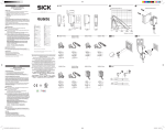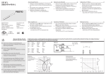
1
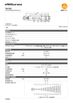
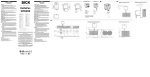
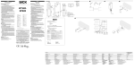
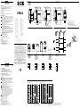
ENGLISH A GTB10-PnnnnGTB10-Rnnnn Photoelectric proximity sensor with background suppression Operating instructions GTB10-Nnnnn GTB10-Fnnnn GTB10-Ennnn DEUTSCH Please find detailed addresses and additional representatives and agencies in all major industrial nations at www.sick.com 9.4 (.25) (.37) 3 5° 10 5° 10 7.7 (.3) A1 42.9 (1.69) B C q (PNP) L More representatives and agencies at www.sick.com ∙ Subject to change without notice ∙ The specified product features and technical data do not represent any guarantee. Weitere Niederlassungen finden Sie unter www.sick.com ∙ Irrtümer und Ä nderungen vorbehalten ∙ Angegebene Produkteigenschaften und technische Daten stellen keine Garantieerklärung dar. Plus de représentations et d’agences à l’adresse www.sick.com ∙ Sujet à modification sans préavis ∙ Les caractéristiques de produit et techniques indiquées ne constituent pas de déclaration de garantie. Para mais representantes e agências, consulte www.sick.com ∙ Alterações poderão ser feitas sem prévio aviso ∙ As características do produto e os dados técnicos apresentados não constituem declaração de garantia. Altri rappresentanti ed agenzie si trovano su www.sick.com ∙ Contenuti soggetti a modifiche senza preavviso ∙ Le caratteristiche del prodotto e i dati tecnici non rappresentano una dichiarazione di garanzia. Más representantes y agencias en www.sick.com ∙ Sujeto a cambio sin previo aviso ∙ Las características y los datos técnicos especificados no constituyen ninguna declaración de garantía. 欲了解更多代表机构和代理商信息,请登录 www.sick.com ∙ 如有更改 , 不另行通知 ∙ 对所给出的产品特性和技术参数 的正确性不予保证。 その他の営業所は www.sick.com よりご覧ください ∙ 予告なし に変更されることがあります ∙ 記載されている製品機能およ び技術データは保証を明示するものではありません。 1 0 q (NPN) 1 0 L q (PNP) D GTB10-P1nnn GTB10-N1nnn GTB10-P8nnn GTB10-N8nnn brn blu blk 6 Sensing range adjustment 7 Light/dark selector brn 1 + (L+) wht 2 - (M) blu 3 Q blk 4 brn + (L+) blk not connected wht - (M) blu Q 1 0 D GTB10-P4nnn GTB10-F2nnn GTB10-N4nnn GTB10-E2nnn GTB10-P6nnn GTB10-N6nnn GTB10-P7nnn GTB10-N7nnn Sicherheitshinweise GTB10-E4nnn GTB10-F4nnn GTB10-E6nnn GTB10-F6nnn GTB10-E7nnn GTB10-F7nnn brn 1 L+ blk 4 wht 2 blu M 3 L+ D GTB10-R3nnn GTB10-R9nnn brn wht M 1 0 q (NPN) blu L1 N blk gra Kein Sicherheitsbauteil gemäß EU-Maschinenrichtlinie. Vor der Inbetriebnahme die Betriebsanleitung lesen. UL: Nur für NFPA 79-Anwendungen Anschluss, Montage und Einstellung nur durch Fachpersonal. Gerät bei Inbetriebnahme vor Feuchte und Verunreinigung schützen. Bestimmungsgemäße Verwendung Die optoelektronischen Sensoren GTB10 werden zum optischen, berührungslosen Erfassen von Objekten eingesetzt. Inbetriebnahme E GTB10-xnn1nGSE-xnn2n % of sensing range 25 GTB10-Xnn1n % of sensing range 25 20 20 15 15 18% / 90% 10 6% / 90% 3 5 90% / 90% 1 0 0 200 (7.87) 400 (15.75) 600 (23.62) 800 (31.5) 1,000 (39.37) Distance in mm (inch) GTB10-Xnn2n 6% / 90% 3 18% / 90% 10 2 Wartung SICK-Lichtschranken sind wartungsfrei. Wir empfehlen, in r egelmäßigen Abständen – die optischen Grenzflächen zu reinigen, – Verschraubungen und Steckverbindungen zu überprüfen. – Kein Alkohol zur Reinigung verwenden. Veränderungen an Geräten dürfen nicht vorgenommen werden. 1 2 3 4 5 30.2 (1.19) Reflexions-Lichttaster mit Hintergrundausblendung Betriebsanleitung 1 Gerät an die Spannungsversorgung anschließen: Bei Geräten mit Anschlussstecker Leitungsdose spannungsfrei aufstecken und festschrauben. Die einzelnen Adern der Anschlussleitung entsprechend Grafik [D] anschließen. Betriebsspannung anlegen. Grüne Anzeige-LED leuchtet. 2 Einsatzbedingungen prüfen: Tastweite und Distanz zum Objekt bzw. Hintergrund sowie Remissionsvermögen des Objektes mit dem zugehörigen Diagramm [E] abgleichen. (Remission: 6 % = schwarz, 18 % = grau, 90 % = weiß) 3 Lichtfleck auf Objekt ausrichten. Objekt wird sicher erkannt, wenn gelbe Anzeige-LED konstant leuchtet. 4 Einstellung der Tastweite mit Potentiometer: Detektionsobjekt im Strahlengang positionieren. Potentiometer nach rechts drehen bis gelbe Anzeige-LED konstant leuchtet. Objekt entfernen, gelbe Anzeige-LED erlischt, Einstellung ist beendet. Falls gelbe Anzeige-LED nicht erlischt oder blinkt, Potentiometer langsam nach links drehen bis gelbe Anzeige-LED erlischt. Objekt erneut positionieren. Leuchtet die gelbe Anzeige-LED konstant, ist die Einstellung beendet. Sollte eine sichere Objektdetektion nicht gewährleistet sein, Einsatzbedingungen prüfen (siehe 2). 5 Einstellung hell- / dunkelschaltend [ A1 ]: Drehschalter auf L = hellschaltend Drehschalter auf D = dunkelschaltend GTB10-Rnnnn: Schaltverhalten entspricht Q (PNP), L; [B] 5 4 50 (1.97) 36 (1.42) 3 M12/4pin BZ int40 SICK light barriers are maintenance-free. We recommend doing the following regularly - clean the external lens surfaces - check the screw connections and plug-in connections. - Do not use alcohol for cleaning. No modifications may be made to devices. 51.5 (2.03) 47.4 (1.87) 6.4 50 (1.97) 36 (1.42) 36 (1.42) (.14) 50 (1.97) 3 SICK AG, Erwin-Sick-Strasse 1, D-79183 Waldkirch Maintenance >> >> >> >> >> 3 (.25) Österreich Phone +43 (0)22 36 62 28 8-0 Norge Phone +47 67 81 50 00 Polska Phone +48 22 837 40 50 România Phone +40 356 171 120 Russia Phone +7-495-775-05-30 Schweiz Phone +41 41 619 29 39 Singapore Phone +65 6744 3732 Slovenija Phone +386 (0)1-47 69 990 South Africa Phone +27 11 472 3733 South Korea Phone +82 2 786 6321/4 Suomi Phone +358-9-25 15 800 Sverige Phone +46 10 110 10 00 Taiwan Phone +886-2-2375-6288 Türkiye Phone +90 (216) 528 50 00 United Arab Emirates Phone +971 (0) 4 8865 878 USA/México Phone +1(952) 941-6780 3 0.5 (.02) 38.8 (1.53) 34.7 (1.37) 6.4 Australia Phone +61 3 9457 0600 Belgium/Luxembourg Phone +32 (0)2 466 55 66 Brasil Phone +55 11 3215-4900 Canada Phone +1 905 771 14 44 Ceská Republika Phone +420 2 57 91 18 50 China Phone +86 4000 121 000 +852-2153 6300 Danmark Phone +45 45 82 64 00 Deutschland Phone +49 211 5301-301 España Phone +34 93 480 31 00 France Phone +33 1 64 62 35 00 Great Britain Phone +44 (0)1727 831121 India Phone +91–22–4033 8333 Israel Phone +972-4-6801000 Italia Phone +39 02 27 43 41 Japan Phone +81 (0)3 3358 1341 Magyarország Phone +36 1 371 2680 Nederlands Phone +31 (0)30 229 25 44 1 3 (.37) 1 Connect the device to the power supply: For devices with plug connectors, attach the cable socket while the device is deenergized and screw it in tightly. Connect the individual wires of the connecting cable as shown in Graphic [D]. Switch on the operating voltage. The green indicator LED lights up. 2 Check the application conditions: Adjust the sensing range and distance to the object or background and the remission of the objectaccording to the corresponding diagram [E]. (Reflectance: 6 % = black, 18 % = gray, 90 % = white) 3 Direct light spot onto the object. The object is positively identified when the yellow indicator LED lights up continuously. 4 Sensing range adjustment via potentiometer: Position object for detection in the beam path. Turn the potentiometer clockwise until the yellow indicator LED lights up continuously. Remove the object, the yellow indicator LED switches off, adjustment is complete. If the yellow indicator LED does not go out or if it flashes, slowly turn the potentiometer counter-clockwise until the yellow indicator LED switches off. Reposition the object. If the yellow indicator LED lights up continuously, adjustment is complete. If the object cannot be positively detected, check the application conditions (see 2). 5 Setting light/dark switching [ A1 ]: Rotary switch to L = light switching Rotary switch to D = dark switching GTB10-Rnnnn: Switching behavior corresponds to Q (PNP), L; [B] 2 3.5 Starting operation GTB10 (.56) The GTB10 is a photoelectric sensor for the optical, noncontact detection of objects. 0.5 (.02) 38.8 (1.53) 34.7 (1.37) 20 (.79) 14.2 Correct use 0.5 (.02) --------------------------------------------------------------------- 8016624 1013 CV -------------------------------------------------------------------- (.46) Not a safety component in accordance with EU Machinery Directive. Read the operating instructions before commissioning. UL: Only for NFPA 79 applications Connection, mounting, and setting is only to be performed by trained specialists. >> When commissioning, protect the device from moisture and contamination. 11.6 >> >> >> >> 19.7 (.78) 9.4 Safety notes 2 5 0 90% / 90% 1 0 200 400 600 800 1,000 1,200 1,400 (7.87) (15.75) (23.62) (31.5) (39.37) (47.24) (55.12) Distance in mm (inch) 1 Sensing range on white, 90 % remission 2 Sensing range on grey, 18 % remission 3 Sensing range on black, 6 % remission Center of optical axis, sender Center of optical axis, receiver Mounting hole, Ø 4.2 mm LED indicator yellow: Light received LED signal strength indicator green: power on Sensing range max. Light source / type Light spot diameter / distance Supply voltage VS Switching output Output current Imax. / Switching current Imax. Switching frequency max. Response time Enclosure rating Protection class Schaltabstand max. Lichtquelle / Lichtart Lichtfleckdurchmesser / Entfernung Versorgungsspannung UV Schaltausgang Ausgangsstrom Imax. / Schaltstrom Imax. Schaltfolge max. Ansprechzeit Schutzart Schutzklasse Distance de commutation max. Type de source / type de lumière Diamètre de la tache lumineuse / distance Tension d‘alimentation UV Sortie de commutation Courant de sortie Imax. / Courant de commutation Imax. Fréquence max. Temps de réponse Type de protection Classe de protection Schutzschaltungen Betriebsumgebungstemperatur Circuits de protection Température ambiante Circuitos protetores Temperatura ambiente de operação 1) 2) 1) 2) 1) 2) 1) 2) 3) 4) 5) 6) 7) 3) 4) 5) 6) 7) Objekt 90 % Remission nach DIN 5033 Grenzwerte; Restwelligkeit max. 5 VSS; Betrieb im kurzschlussgeschützen Netz max. 8 A; UL: Geräteschutz: 1 A-Sicherung +/- 10 %. UL: Geräteschutz: 2 A-Sicherung. UL enclosure type 1 Bemessungsspannung AC 250 V A = UV -Anschlüsse verpolsicher B = Ein- und Ausgänge verpolsicher C = Störimpulsunterdrückung D = Ausgänge überstrom- und kurzschlussfest UL: 0 ... +60 ° C 3) 4) 5) 6) 7) Objet Luminance de 90 % selon DIN 5033 Valeurs limites; Ondulation résiduelle max. 5 VSS; Service dans un réseau protégév contre les courts-circuits 8 A au max. UL : protection appareil : fusible 1 A +/- 10 % UL : protection appareil : fusible 2 A UL enclosure type 1 Tension de calcul AC 250 V A = Raccordements UV protégés contre B = Entrée et sortie sécurisées en mat. de polarisation C = Suppression des impulsions parasites D = Sortie résistant au courant de surcharge et aux courts-circuits UL: 0 ... +60 ° C 输出电流Imax. / 最大开关电流 Imax. 最大出力電流 Imax. / 最大出力電流 Imax. 信号流 max. 触发时间 切替順序 max. 応答時間 1) 2) Circuitos de protección Temperatura ambiente de servicio 保护电路 保護回路 工作环境-温度 使用周囲温度 1) 2) 1) 2) 1) 2) 3) 4) 5) 6) 7) Objeto 90 % de remission en base a DIN 5033 Valores límite; Ondulación residual max. 5 VSS; Funcionamiento en la red protegida contra cortocircuito, max. 8 A UL: protección del aparato: fusible de 1 A +/- 10 % UL: protección del aparato: fusible de 2 A UL enclosure type 1 Tensión tolerable AC 250 V A = Conexiones UV a prueba de inversión de polaridad B = Entradas y salidas protegidas contra polarización incorrecta C = Represión de impulso de interferencia D = Salidas a prueba de sobrecorriente y cortocircuitos UL: 0 ... +60 ° C FRANÇAIS Détecteur réflex avec élimination d’arrière-plan Manuel d’utilisations Remarques relatives à la sécurité >> Il ne s’agit pas d’un composant de sécurité conformément à la Directive CE sur les machines. >> Lire le manuel d’utilisation avant la mise en service. >> UL : uniquement pour applications NFPA 79 >> Faire effectuer le raccordement, le montage et le réglage uniquement par un personnel spécialisé. >> Protéger l’appareil de l’humidité et des impuretés lors de la mise en service. 3) 4) 5) 6) 7) 90 % 漫反射比物体按照 DIN 5033 操作电流; 极限值剩余波纹度 max. 5 VSS; 在防短路的网络里, 最大8 UL: 设备保护:1 A 保险丝 +/- 10 %.UL:设备保护:2 A 保险丝。 UL enclosure type 1 限定电压 AC 250 V A = UV-接头防反接 B = 具有反极性保护的输入端和输出端 C = 消除干扰脉冲 D = 抗过载电流和抗短路输出端 UL: 0 ... +60 ° C PORTUGUÊS Notas de segurança >> Os componentes de segurança não se encontram em conformidade com a Diretiva Europeia de Máquinas. >> Ler as instruções de operação antes da colocação em funcionamento. >> UL: Somente para aplicações NFPA 79 >> A conexão, a montagem e o ajuste devem ser executados somente por pessoal técnico qualificado. >> Durante o funcionamento, manter o aparelho protegido contra impurezas e umidade. Avvertenze sulla sicurezza >> Nessun componente di sicurezza conformemente alla direttiva macchine UE. >> Prima della messa in funzione leggere le istruzioni d’uso. >> UL: solo per applicazioni NFPA 79 >> Allacciamento, montaggio e regolazione solo a cura di personale tecnico specializzato. >> Alla messa in funzione proteggere l’apparecchio dall’umidità e dalla sporcizia. Os sensores optoeletrônicos GTB10 são utilizados para a detecção óptica e sem contato de objetos. I sensori fotoelettronici GTB10 sono impiegati per il rilevamento ottico a distanza di oggetti. Mise en service Colocação em funcionamento Messa in funzione Manutenção As barreiras de luz SICK não requerem manutenção. Recomendamos que se efetue em intervalos regulares - uma limpeza das superfícies ópticas - uma verificação das conexões roscadas e dos conectores. - Não utilize produtos à base de álcool para a limpeza. Não são permitidas modificações no aparelho. 1 C ollegare l‘apparecchio all‘alimentazione elettrica: in caso di apparecchi con connettore, inserire la spina con tensione disinserita e avvitarla a fondo. Collegare i singoli fili del cavo di allacciamento conformemente al grafico [D]. Mettere in tensione l‘apparecchio. Il LED verde si illumina. 2 Controllare le condizioni di utilizzo: uniformare la distanza di tastatura e la distanza dall’oggetto o dallo sfondo, nonché la remissione dell’oggetto secondo il relativo diagramma [E]. Riflettenza: 6 % = nero, 18 % = grigio, 90 % = bianco (bianco standard DIN 5033) 3 Dirigere il punto luminoso sull’oggetto. L’oggetto viene riconosciuto in sicurezza se il LED giallo è illuminatofisso. 4 Regolazione della distanza di tastatura con potenziometro: Posizionare l’oggetto da rilevare nel raggio di scansione. Ruotare il potenziometro verso destra fino a quando il LED giallo è illuminato fisso. Togliere l’oggetto, il LED giallo si spegne, la regolazione è terminata. Se il LED giallo non si spegne o se lampeggia, ruotare lentamente il potenziometro verso sinistra fino a quando il LED giallo si spegne. Posizionare nuovamente l’oggetto. Se il LED giallo è illuminato fisso, la regolazione è terminata. Se non fosse garantito un rilevamento in sicurezza dell’oggetto, controllare le condizioni di utilizzo (vedere 2). 5 Regolazione chiaro / scuro [ A1 ]: Interruttore rotante su L = chiaro Interruttore rotante su D = scuro GTB10-Rnnnn: Commutazione corrisponde a Q (PNP), L; [B] Manutenzione 500 Hz ≤ 1 ms GTB10-Rnn1n GTB10-Rnn2n 20 ... 1200 mm 1) LED / infared 20 ... 950 mm 1) PinPoint LED / red light 20 ... 1200 mmm 1) LED / infared 22 mm / 700 mm 8 mm / 700 mm 22 mm / 700 mm AC / DC 24 ... 240 V 3) Relay SPDT (electrically isolated) 0.11 A (250 VDC), 3 A (30 VDC), 3 A (250 VAC) 20 Hz ≤ 10 ms GTB10-Pnn2n (PNP) GTB10-Fnn2n (PNP) GTB10-Nnn2n (NPN) GTB10-Enn2n (NPN) 1000 Hz ≤ 500µs 5) C 6) -30 … +60 °C 7) ESPAÑOL Barrera de luz de reflexión con ocultación de fondo Instrucciones de servicio Sensore luminoso a riflessione con soppressione dello sfondo Struzioni d’uso Les capteurs opto-électroniques GTB10 sont utilisés pour la détection optique d‘objets sans contact. Maintenance GTB10-Pnn5n (PNP) GTB10-Fnn5n (PNP) GTB10-Nnn5n (NPN) GTB10-Enn5n (NPN) UL: 装置保護: 1 A ヒューズ +/- 10 %.UL: 装置保護: 2 A ヒューズ UL enclosure type 1 定格電圧 AC 250 V 6) A = U 接続逆接保護 V B = 出入力 逆接保護 C = 干渉パルス制御 D = 出力の過電流保護および短絡保護 7) UL: 0 ... +60 ° C Impiego conforme agli usi previsti 1 Conectar o dispositivo à alimentação de tensão: para os dispositivos com plugue de conexão, encaixar e aparafusar o conector de cabos sem tensão. Conectar os fios do cabo de conexão de acordo com a ilustração [D]. Aplicar a tensão de operação. O indicador LED verde acende. 2 Verificar as condições de uso: equiparar o alcance de detecção edistância até o objeto ou plano de fundo, bem como a refletividade do objeto com o respectivo diagrama [E]. Remissão: 6 % = preto, 18 % = cinzento, 90 % = branco (em função do branco normal segundo DIN 5033) 3 Alinhar o ponto luminoso sobre o objeto. O objeto está sendo detectado com certeza, se o indicador LED amarelo estiver constantemente aceso. 4 Ajuste do alcance de detecção com potenciômetro: Posicionar o objeto de detecção no feixe luminoso. Girar o potenciômetro para a direita até o indicador LED amarelo estar constantemente aceso. Retirar o objeto, o indicador LED amarelo apaga, o ajuste está terminado. Se o indicador LED amarelo não apagar ou piscar, girar o potenciômetro lentamente para a esquerda até o indicador LED amarelo apagar. Reposicionar o objeto. Se o indicador LED amarelo estiver constantemente aceso, o ajuste está terminado. Se não estiver assegurada uma detecção confiável do objeto, verificar as condições de uso (ver 2). 5 Ajuste comutação por sombra / luz [ A1 ]: Botão seletor em L = comutação por luz Botão seletor em D = comutação por sombra GTB10-Rnnnn: As características de comutação correspondem Q (PNP), L; [B] 1000 Hz ≤ 500µs 3) 4) 5) Especificações de uso 1 Raccorder l‘appareil à son alimentation électrique : sur les appareils munis d‘un connecteur, introduire la prise hors tension et la visser. Raccorder chaque fil du câble de raccordement selon le graphique correspondant [D]. Puis mettre l‘appareil sous tension. La LED verte s‘allume. 2 Vérifier les conditions d’utilisation : contrôler la portée et la distance à l’objet ou l’arrière-plan ainsi que les caractéristiques de réflectivité de l’objet à l’aide du diagramme [E] correspondant. Luminance: 6 % = noir, 18 % = gris, 90 % = blanc (par rapport au blanc étalon selon DIN 5033) 3 Orienter le spot lumineux vers l’objet. L’objet est détecté avec certitude lorsque la LED jaune est allumée en continu. 4 Réglage de la distance de détection avec le potentiomètre : Placer l’objet à détecter sur le trajet du faisceau. Tourner le potentiomètre vers la droite, jusqu’à ce que la LED jaune s’allume en continu. Ôter l’objet, la LED jaune s’éteint ; le réglage est terminé. Si la LED jaune ne s’éteint pas ou clignote, tourner lentement le potentiomètre vers la gauche jusqu’à ce que la LED s’éteigne. Remettre l’objet en position. Lorsque la LED jaune est allumée en continu, le réglage est terminé. Si une détection fiable de l’objet ne semble pas garantie, vérifier les conditions d’installation (voir 2). 5 Réglage commutation clair / sombre [ A1 ] : Sélecteur sur L = commutation claire Sélecteur sur D = commutation sombre GTB10-Rnnnn: Comportement de la sortie de commutation correspond à Q (PNP), L ; [B] 8 mm / 700 mm 22 mm / 700 mm AC / DC 24 ... 240 V 3) Relay SPDT (electrically isolated) 0.11 A (250 VDC), 3 A (30 VDC), 3 A (250 VAC) 20 Hz ≤ 10 ms A, B, C, D 6) -30 … +60 °C ITALIANO Foto-célula de reflexão no objeto com redução da intensidade da luz do plano de fundo Instruções de operação 22 mm / 700 mm 対象物 90 % の反射率 DIN 5033 に準拠 限界値; 最大 5 VSS; 短絡防止回路での動作 最大 8 A、残留リップル Utilisation conforme Les barrières lumineuses SICK sont sans entretien. Nous vous recommandons de procéder régulièrement - au nettoyage des surfaces optiques - au contrôle des liaisons vissées et des connexions. - Ne pas utiliser d‘alcool pour le nettoyage. Ne procédez à aucune modification sur les appareils. GTB10-Pnn1n (PNP) GTB10-Fnn1n (PNP) GTB10-Nnn1n (NPN) GTB10-Enn1n (NPN) 8 mm / 700 m DC 10 ... 30 V 2) PNP / NPN 100 mA 1000 Hz ≤ 500µs IP 67 4) Commutazioni di protezione Temperatura ambiente circostante 20 ... 1200 mmm 1) LED / infared -30 … +60 °C 7) スポット径 / 距離 保護等級 20 ... 950 mm 1) PinPoint LED / red light -30 … +60 °C 供給電圧 UV スイッチング出力 保護クラス 20 ... 1200 mm 1) LED / infared C 6) 电源电压UV 开关输出端 保护级别 GTB10-Rnn2n 5) Objeto: 90 % de remissão segundo DIN 5033 Valores limite; Ondulação residual max. 5 VSS; Operação em rede protegida contra curto-circuitos max. 8 A UL: Proteção do dispositivo: fusível 1 A +/- 10 %. UL: Proteção do dispositivo: fusível 2 A UL enclosure type 1 Tensão de dimensionamento AC 250 V A = Conexões UV protegidas contra inversão de polos B = Entradas e saídas protegidas con tra polaridade inversa C = Supressão de impulsos parasitas D = Saídas protegidas contra sobrecorrente e curto-circuito. UL: 0 ... +60 ° C 保护种类 GTB10-Rnn1n GTB10-Pnn2n (PNP) GTB10-Fnn2n (PNP) GTB10-Nnn2n (NPN) GTB10-Enn2n (NPN) A, B, C, D 6) 光点直径 / 距离 检测范围, max. 光源 / 种类 7) 7) GTB10-Pnn5n (PNP) GTB10-Fnn5n (PNP) GTB10-Nnn5n (NPN) GTB10-Enn5n (NPN) 500 Hz ≤ 1 ms 20 ... 950 mm 1) PinPoint LED / red light Distancia de conmutación max. Fuente de luz / tipo de luz Diámetro / distancia de mancha de luz Tensión de alimentación UV Salida conmutada Corriente de salida Imax. / Intensidad de conmutación Imax. Secuencia de señales max. Tiempo de reacción Tipo de protección Protección clase 3) 4) 5) 6) 3) 4) 5) 6) 8 mm / 700 m DC 10 ... 30 V 2) PNP / NPN 100 mA 1000 Hz ≤ 500µs IP 67 4) スイッチ間隔、max. 光源 / 発光タイプ Distanza di commutazione max. Sorgente luminosa / tipo di luce Diametro punto luminoso / distanza Tensione di alimentazione UV Uscita di commutazione Corrente di uscita Imax. / Corrente di commutazione Imax. Sequenza signali max. Tempo di risposta Tipo di protezione Classe di protezione Oggetto 90 %, remissione sec. DIN 5033 Valori limite; Ondulazione residua max. 5 VSS; Funzionamento in rete con protezione dai cortocircuiti max. 8 A UL: protezione apparecchio: fusibile 1 A +/- 10 %. UL: protezione apparecchio: fusibile 2 A. UL enclosure type 1 Tensione di taratura AC 250 V A = UV-collegamenti con protez. contro inversione di poli B = Entrate e uscite protette da polarità inversa C = Soppressione impulsi di disturbo D = uscite protette da sovracorrente e da cortocircuito UL: 0 ... +60 ° C 20 ... 950 mm 1) PinPoint LED / red light Distância de comutação max. Fonte de luz / tipo de luz Diâmetro do ponto de luz / distância Tensão de força UV Saída de comutação Corrente de saída Imax. / Corrente de comutação Imax. Sequência max. de sinais Tempo de reação Tipo de proteção Classe de proteção Circuit protection Ambient operating temperature Object 90 % reflection according to DIN 5033 Limit values; Ripple max. 5 Vpp; Operation in short-circuit protected network max. 8 A UL: device protection: 1 A fuse +/- 10 %. UL: device protection: 2 A fuse UL enclosure type 1 Reference voltage AC 250 V A = VS connections reversepolarity protected B = Inputs and output reverse-polarity protected C = Interference pulse suppression D = outputs overcurrent and short-circuit protected UL: 0 ... +60 ° C GTB10-Pnn1n (PNP) GTB10-Fnn1n (PNP) GTB10-Nnn1n (NPN) GTB10-Enn1n (NPN) Le barriere fotoelettriche SICK sono esenti da manutenzione. Consigliamo di pulire in intervalli regolari - le superfici limite ottiche - verificare i collegamenti a vite e gli innesti a spina. - Non utilizzare alcol per la pulizia. Non è consentito effettuare modifiche agli apparecchi. Indicaciones de seguridad >> No se trata de un componente de seguridad según la Directiva de máquinas de la UE. >> Lea las instrucciones de servicio antes de efectuar la puesta en funcionamiento. >> UL: solo para aplicaciones NFPA 79. >> La conexión, el montaje y el ajuste deben ser efectuados exclusivamente por técnicos especialistas. >> Proteja el equipo contra la humedad y la suciedad durante la puesta en funcionamiento. Uso conforme a lo previsto Los sensores optoelectrónicos GTB10 son utilizados para la captura óptica sin contacto de objetos. Puesta en funcionamiento 1 Conectar el aparato a la fuente de alimentación: en los aparatos con enchufe de conexión, insertarlo en la toma de corriente sin tensión y atornillarlo. Conectar los conductores del cable de conexión conforme a la figura [D]. Conectar a la tensión de servicio. El LED indicador verde se ilumina. 2 Comprobar las condiciones de aplicación: comparar el alcance de detección y la distancia respecto al objeto o el fondo, así como la capacidad de remisión del objeto, con el diagrama correspondiente [E]. Reflexión espectral: 6 % = negra, 18 % = gris, 90 % = blanca (referida a blanco estándar en base a la norma DIN 5033). 3 Oriente el punto luminoso sobre el objeto. El objeto se detecta de forma fiable cuando el LED indicador amarillo se ilumina permanentemente. 4 Ajuste de la distancia de detección mediante potenciómetro: Posicionar el objeto a detectar en la trayectoria del haz. Girar el potenciómetro hacia la derecha hasta que el LED indicador amarillo se ilumine permanentemente. Retirar el objeto; el LED indicador amarillo se apaga. El ajuste ha finalizado. Si el LED indicador amarillo no se apaga o parpadea, girar lentamente el potenciómetro hacia la izquierda hasta que se apague. Posicionar el objeto de nuevo. Si el LED indicador amarillo permanece encendido, el ajuste ha finalizado. Si no se asegura una detección fiable del objeto, comprobar las condiciones de aplicación (véase 2). 5 Ajuste de conmutación en claro/oscuro [ A1 ]: Interruptor giratorio en L: conmutación en claro Interruptor giratorio en D: conmutación en oscuro GTB10-Rnnnn: El comportamiento de conmutación corresponde a Q (PNP), L; [B] Mantenimiento Las barreras fotoeléctricas SICK no precisan mantenimiento. En intervalos regulares, recomendamos - limpiar las superficies ópticas externas - comprobar las uniones roscadas y las conexiones. - No utilizar alcohol como agente limpiador. No se permite realizar modificaciones en los aparatos. 中文 日本語 反射式光电扫描仪 带背景抑制功能 操作规程 反射形光電スイッチ 背景抑制機能付き 取扱説明書 安全须知 >> 本设备非欧盟机械指令中定义的安全部件。 >> 调试前请阅读操作规程。 >> UL:仅适合 NFPA 79 应用 >> 仅允许由专业人员进行接线、安装和设置。 >> 调试时应防止设备受潮或脏污。 正确使用须知 光电传感器 GTB10 用于非接触式 光学检测物体。 调试 1 将设备连接至电源:如果设备配备插头,应在未通电时插入并旋紧电缆 插头。 根据图 [D] 连接接线电缆的各个缆芯。 接通工作电压。绿色 LED 指示灯亮起。 2 检查使用条件:使用随附的示意图 [E] 校正至物体或背景的扫描范围和距 3 4 安全上の注意事項 >> 本製品は EU 機械指令の要件を満たす安全コンポーネントではありま せん。 >> 使用を開始する前に取扱説明書をお読みください。 >> UL: NFPA 79 アプリケーションの場合のみ >> 接続、取付けおよび設定できるのは専門技術者に限ります。 >> 装置を使用開始する際には、濡れたり汚れたりしないように保護して ください。 使用目的 光電センサ GTB10 は、対象物を光学技術により非接触で検出するための 装置です。 使用開始 1 機器を電源供給に接続します:接続プラグ付き機器の場合には、配線 コンセントを無電圧状態で差込み、ネジ止めします。 接続配線の個々 の線を図 [D] に従って接続します。 動作電圧を供給します。緑色の LED 表示灯が点灯します。 离,以及物体的反射能力。 漫反射:6 % = 黑色,18 % = 灰色,90 % = 白色 (以DIN5033中规定的标准白色为基准) 2 動作条件を点検します:検出範囲および対象物までの距離、または背景 および対象物の反射率を、関連するダイアグラム [E] と比較します。反 光斑对准物体。 将 如果黄色 LED 指示灯持续亮起,则表明识别到物体。 射率:6 % = 黒、18 % = グレー、 90 % = 白 (DIN 5033 に準拠した白) 3 対象物に光を合わせます。 用电位计调整扫描范围: 使 将探测物体定位在光路中。 向右转动电位计直至黄色 LED 指示灯持续亮起。移开物体,黄色 LED 指 示灯熄灭,调整结束。 如果黄色 LED 指示灯未熄灭或闪烁,则缓慢向左转动电位计直至黄色 LED 指示灯熄灭。重新定位物体。 如果黄色 LED 指示灯持续亮起, 则调整结束。 如果无法确保能够探测到物体,则检查使用条件(参见 2)。 5 开灯 / 关灯设置 [ A1 ]: 转开关置于 L = 开灯 旋 旋转开关置于 D = 关灯 GTB10-Rnnnn: 开关特性符合 Q (PNP), L; [B] SICK 光电开关无需保养。我们建议,定期 - 清洁镜头检测面 - 检查螺丝接头和插头连接。 - 不得使用酒精进行清洁。 不得对设备进行任何改装。 4 5 黄色い LED 表示灯が継続的に点灯している場合、リフレクタが確実に 検出されています。 テンショメータを用いた検出範囲の設定: ポ 検査対象物を照射経路に位置づけます。 黄色い LED 表示灯 が継続的に点灯するまで、ポテンショメータを右 に回します。 対象物を取り除くと、黄色い LED 表示灯が消灯し、設定 が終了します。 黄色受光表示 LED が消えない、または点滅しない場合は、黄色い LED 表示灯が消えるまでポテンショメータを慎重に左方向へ回します。対 象物を再度位置付けします。 黄色い LED 表示灯が継続的に点灯してい る場合、設定は終了しています。 確実な対象物検出が確保できない場合は、動作条件を点検します (2 を参照)。 設定 ライトオン / ダークオン[ A1 ]: ータリースイッチ L = ライトオン ロ ロータリースイッチ D = ダークオン GTB10-Rnnnn: スイッチング動作は Q (PNP)、L に対応; [B] SICK の光電スイッチはメンテナンス不要です。 推奨する定期的な保全作業 - レンズ境界面の清掃 - ネジ締結と差込み締結の点検 - 清掃にアルコールを使用しないでください。 デバイスに変更を加えることは一切禁止されています。