1
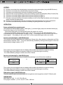
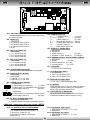
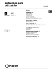
KIT NE185-T
NE154 NE152 NE188
NE148-T
NE143
I
GB
NE185-T
NE143-20
ISTRUZIONI D’USO
INSTRUCTIONS MANUAL
F
INSTRUCTIONS D’EMPLOI
D
BEDIENUNGSANLEITUNG
Mod. NE154
Mod. NE152
Mod. NE188
mod. NE148 2006
mod. NE185
mod. NE143
2
PANNELLO COMANDI NE154
I
COMANDI:
Pulsante con spia per accensione o spegnimento LUCI INTERNE
Pulsante con spia per accensione o spegnimento LUCE ESTERNA
Pulsante con spia per accensione o spegnimento POMPA
VISUALIZZAZIONI:
Sulla videata principale e’ sempre visualizzata la data, l’ora, la temperatura interna e quella esterna.
Se il sensore di temperatura non e’ presente o e’ guasto vengono visualizzati 3 trattini al posto della
temperatura. Se è presente la rete, sul display appare il simbolo
. Se un fusibile del derivatore
NE148/NE185 è bruciato, sul display appare il simbolo
.
Si può regolare il contrasto del display ruotando il perno bianco sul retro del pannello.
Premendo una volta questo tasto si visualizza il livello del serbatoio acqua potabile S1. Premendo
nuovamente il tasto si visualizzano i livelli dei serbatoi recupero S2-S3.
Opzionale: Se presente l’accessorio “sonda a litri” (mod. Ne131), sul rispettivo serbatoio la misura
non sarà più a livelli ma lineare con un’indicazione a litri.
Le videate rimangono attive per circa 30 sec.
Tasto per visualizzare la tensione della batteria servizi (B2) e della batteria di avviamento (B1).
Opzionale: Se presente l’accessorio shunt amperometrico premendo due volte il tasto compare la
videata per la lettura della corrente di carica o scarica della batteria servizi.
Le videate rimangono attive per circa 30 sec.
PROGRAMMAZIONE:
Tenendo premuto questo tasto per piu’ di due secondi si entra nel menu’ programmazione.
Con i tasti freccie ( ) ( ) si cambia pagina. Premendo il tasto enter ( ) ripetutamente si entra
nella pagina e si seleziona il valore da modificare. Utilizzano i tasti freccie si può incrementare o
decrementare il valore selezionato, mentre con il tasto cancel ( ) si esce dalla funzione salvando il
dato.
Le pagine disponibili sono:
- Regolazione data e ora
- Regolazione e abilitazione sveglia. Quando la svegia e’ abilitata compare sulla videata
principale una campanella. La sveglia suonerà per 30 sec. e basterà pigiare qualsiasi tasto per
fermarla
- Abilitazione allarmi serbatoi: serbatoio acqua potabile vuoto, serbatoi recupero pieni.
Quando si verifica si genera un allarme sonoro intermittente per 5 sec. e contemporaneamente
sul display comparirà la finestra di visualizzazione dei serbatoi.
- Abilitazione allarme batteria servizi e batteria auto scariche. Ogni volta che la batteria
auto scende sotto gli 11V o la batteria servizi scende sotto i 10V si genera un allarme
sonoro intermittente per 5 sec. e contemporaneamente sul display comparirà la finestra di
visualizzazione delle tensioni batterie.
- Abilitazione del beep dei tasti.
GESTIONE CONSUMI
Per accendere il pannello comandi si deve premere il tasto
In modalità stand-by (senza comandi attivi) il pannello comandi con il derivatore NE148/NE185 hanno un
consumo totale di circa 37mA. Tenendo premuto il tasto per più di 3 secondi si spegne il pannello comandi
riducendo a soli 12mA il consumo totale.
Se la tensione della batteria servizi scende sotto i 9,5V si verifica un autospegnimento del pannello comandi.
BATTERIA MEMORIA
Sul retro del pannello è presente una batteria tampone (LITIO 3V CR2032) per mantenere l’orario e le varie
programmazioni in mancanza dell’alimentazione pannello.
DIMENSIONI:
(L x H) 188 x 118 mm
3
I
I
PANNELLO COMANDI NE152/NE188
COMANDI:
Pulsante con spia per accensione o spegnimento LUCI INTERNE
Pulsante con spia per accensione o spegnimento LUCE ESTERNA
Pulsante con spia per accensione o spegnimento POMPA
VISUALIZZAZIONI:
Se è presente la rete si accende il led
si accende il led
.
230V
. Se un fusibile del derivatore NE148/NE185 è bruciato
Premendo una volta questo tasto si visualizza il livello del serbatoio acqua potabile S1 e il livello del
serbatoio recupero S2. Premendo nuovamente il tasto si visualizza sempre il serbatoio S1 e il livello
del serbatoio recupero S3.
Se durante la visualizzazione il led 3/3 è lampeggiante, segnala che i collegamenti al serbatoio sono
sbagliati
La visualizzazione rimane attiva per circa 30 sec.
Premendo questo tasto si visualizza la tensione della batteria servizi (B2) e della batteria di
avviamento (B1).
Quando è presente la rete i led del voltmetro B2 si accendono in sequenza (fino a quello
corrispondente al valore di batteria) per segnalare che la batteria servizi B2 è in carica.
La visualizzazione rimane attiva per circa 30 sec.
La corrispondenza tra led e valori di tensione è la seguente:
Led rosso lampeggiante
Led rosso acceso
Led verde 1/3 acceso
Led verde 2/3 acceso
Led verde 3/3 acceso
<10V
10÷11V
11÷12V
12÷12,6V
>12,6V
ALLARMI:
Batterie: Batteria auto (B1) minore di 11V o Batteria servizi (B2) minore di 10V.
In questo caso si verifica un allarme sonoro (se abilitato) e il lampeggio del led tasto Test
batterie insieme al led (R) della rispettiva batterie che ha generato l’allarme.
Serbatoi: Serbatoio S1 vuoto o Serbatoi recupero S2,S3 pieni.
In questo caso si verifica un allarme sonoro (se abilitato) e il lampeggio del led tasto Test
serbatoi insieme al led del corrispondente serbatoio che ha generato l’allarme.
Abilitazione o disabilitazione allarme sonoro:
Tenendo premuto per più di 2 secondi il tasto Test serbatoi inizierà a lampeggiare il led del suddetto
tasto e si potrà:
Con il tasto generale luci: abilitare (spia accesa) o disabilitare (spia spenta) l’allarme sonoro serbatoi
Con il tasto luce esterna: come sopra per l’allarme sonoro batterie scariche
Con il tasto pompa:
come sopra per beep di conferma tasto premuto
GESTIONE CONSUMI
Per accendere il pannello comandi si deve premere il tasto
In modalità stand-by (senza comandi attivi) il pannello comandi con il derivatore NE148/NE185 hanno un
consumo totale di circa 26mA. Tenendo premuto il tasto per più di 3 secondi si spegne il pannello comandi
riducendo a soli 12mA il consumo totale.
Se la tensione della batteria servizi scende sotto i 9,5V si verifica un autospegnimento del pannello comandi.
DIMENSIONI:
(L x H) 188 x 118 mm
4
I
I
DERIVATORE NE185 / NE148-2006
LEGENDA:
F1: Fusibile 5A (solo sul derivatore NE185) collegato alla batteria auto per l'alimentazione delle luci
side marker
F2: Fusibile 20A collegato alla batteria auto per l'alimentazione del frigo.
F3: Fusibile 15A collegato direttamente alla batteria servizi per l’alimentazione scalino
F4: Fusibile 20A/10A collegato direttamente alla batteria servizi per l’alimentazione WEBASTO (20A)
o Combi (10A)
F5: Fusibile 15A collegato all'interruttore generale luci per alimentare il gruppo Luci_1
F6: Fusibile 15A collegato all'interruttore generale luci per alimentare il gruppo Luci_2.
F7: Fusibile 10A collegato direttamente alla batteria servizi per le accensioni del frigo, boiler e
all'interruttore pompa per l'alimentazione della pompa acqua
F8: Fusibile 5A collegato direttamente alla batteria servizi per alimentare le luci di cortesia e
all’interruttore luce esterna
F9: Fusibile 10A collegato direttamente alla batteria servizi per le accensioni della stufa, wc, gas, ecc.
FUNZIONAMENTO:
Utenze azionate dal pannello comandi:
Le uscite luci interne (luci_1 e luci_2), luce esterna, pompa sono azionate direttamente dai relativi tasti
del pannello comandi.
- La luce esterna si spegne automaticamente con il motore in moto.
- Se la tensione di batteria servizi rimane sotto i 10V per più di un minuto, il derivatore NE148/NE185
spegne automaticamente tutte le utenze luci, pompa. Per riattivare i carichi bisogna premere i
corrispondenti tasti sul pannello comandi, ma se la batteria permane sotto i 10V dopo un minuto si
disattiveranno nuovamente.
Utenze azionate dal D+: derivatore NE148
Il relè accoppiatore ed il relè frigo si abilitano se e’ presente il segnale +Chiave (o +alternatore) e se la
batteria avviamento supera i 13,0V. Si disabilitano automaticamente spegnendo il motore o con
tensione di batteria avviamento inferiore a 12,0V.
+Batteria
JP6 pin1
avviamento
+12V
>13V
Il relè accoppiatore provvede alla ricarica della batteria servizi tramite l'alternatore con motore in moto.
Il relè frigo permette di alimentare a 12V il frigo trivalente sempre quando il motore è in moto.
- Se si usa un sistema di ricarica esterna togliere il ponticello J5.
Utenze azionate dal D+: derivatore NE185
Il relè accoppiatore ed il relè frigo si abilitano immediatamante in presenza di una di queste due
condizioni:
G
+Alternatore
JP6 pin1
oppure
KEY-ON
+Chiave
JP13 pin 3
+12V
+12V
D+
D+
JP13 pin 2
attivo
Il relè accoppiatore provvede alla ricarica della batteria servizi tramite l'alternatore con motore in moto.
Il relè frigo permette di alimentare a 12V il frigo trivalente sempre quando il motore è in moto.
- Se si usa un sistema di ricarica esterna togliere il ponticello J5.
Segnale side-marker: derivatore NE185
L’uscite side-marker può essere attivata con un comando negativo (massa) sul blocchetto JP13 pin 4
DIMENSIONI:
Solo scatola a parete: (L x H) 183 x 98 mm
Contenitore completo verticale: (L x H x P) 215 x 102 x 186 mm
5
I
DERIVATORE NE185 / NE148-2006
I
JP13
3 1
4 2
JP6
1
2
JP16
JP2
JP5
10
11
12
7
8
9
4
5
6
1
2
3
RE6
4 3 2 1
RE2
RE3
JP3
1
2
3
4
RE8
1
2
3
4
JP4
1
2
3
4
JP1
4
1
RE1
JP9
1
4
4 3 2 1
JP11
6
3
8
5
2
7
4
1
RE9
1
4
4 3 2 1
J5
JP11: PANNELLO COMANDI
Connettore 4 poli per il collegamento del pannello
comandi tramite l'apposito cavo.
JP5: USCITA UTENZE
9.
Accensione boiler
(F7 10A)
1,4,5,7,8. Accensioni
(F9 10A)
12.
Uscita (+) POMPA
(F7 10A)
6.
Uscita (+) LUCE ESTERNA (F8 5A)
2,3.
Uscita (+) 12V
(F8 5A)
10.
Uscita d+ (max 1A)
11.
Uscita rientro scalino (max 1A)
JP9: SERBATOI potabile (S1)
1. NEGATIVO
2. 1/3 Serbatoio acqua potabile S1
3. 2/3 Serbatoio acqua potabile S1
4. 3/3 Serbatoio acqua potabile S1
5.6. N.c.
JP3: USCITA SCALINO, WEBASTO (ROSSO)
1. NEGATIVO
2. NEGATIVO
3. Uscita (+) SCALINO
(F3 10A)
4. Uscita (+) WEBASTO/COMBI
(F4 20/10A)
JP8: SERBATOI S2
1. NEGATIVO
2. 1/3 Serbatoio recupero S2
3. 2/3 Serbatoio recupero S2
4. 3/3 Serbatoio recupero S2
JP16: PREDISPOSIZIONE PANNELLO SOLARE
(VERDE)
1. NEGATIVO
2. Accensioni
(F7 10A)
3. Batteria Servizi (F3 10A)
4. Batteria Auto
(F2 20A)
JP7: SERBATOI S3
1. NEGATIVO
2. 1/3 Serbatoio recupero S3
3. 2/3 Serbatoio recupero S3
4. 3/3 Serbatoio recupero S3
JP10: SHUNT AMPEROMETRICO
(Non gestito con il pannello NE152/NE188)
JP1 : NEGATIVO
1.2.3.4.5.6.7.8.9: NEGATIVO
JP2: USCITA LUCI (NERO)
1. NEGATIVO
2. NEGATIVO
3. LUCI_1 (+) (F5 15A)
4. LUCI_2 (+) (F6 15A)
J1: INGRESSO BATTERIA AUTO
1,2. NEGATIVO
3. Ingresso + batteria AUTO (B1)
4. Ingresso + batteria AUTO (B1)
J2: INGRESSO BATTERIA SERVIZI (NERO)
1,2,3,4. Ingresso + batteria SERVIZI (B2)
JP4: USCITA FRIGO (BIANCO)
1. NEGATIVO
JP4
2. Alimentazione accensione gas (+) (F7 10A)
3 2 1
3. Uscita (+) frigo azionata da relè (F2 20A)
4. Uscita (+) frigo diretta
(F2 20A)
JP4
2
9
J1
JP10
3
1 2
J2
6
4
JP15
1 2
4
1
JP8
1
J4
JP14
RE4
JP7
1
I
1. NEGATIVO
2. Uscita (+) frigo azionata da relè
3. Uscita (+) frigo diretta
J4 : USCITA D+
Uscita positiva (Max 0,5A) per azionare tutti i carichi
funzionanti con motore in moto (es. frigo AES,
rientro antenna, valvole di scarico, ecc)
J5 : ABILITAZIONE RELE ACCOPPIATORE
Togliendo il ponticello il derivatore non accoppia più
le batterie con motore in moto.
(F2 20A)
(F2 20A)
JP6: INGRESSO D+, P.RETE
1. Ingresso D+ dall'alternatore
2. Ingresso PRESENZA RETE dal carica batterie
Connessioni aggiuntive del derivatore versione NE185
JP13: INGRESSO COMANDI D+, SIDE MARKER
1. n.c.
2. Ingresso D+ comando negativo (C036L1A -2)
3. Ingresso + Chiave (C036L1A -13)
4. Ingresso Side Marker comando negativo
C036L1A -11)
JP15: USCITA SIDE MARKER DESTRO
1. Uscita (+) Side Marker dx (F1 5A)
2. NEGATIVO
JP14: USCITA SIDE MARKER SINISTRO
1. Uscita (+) Side Marker sx (F1 5A)
2. NEGATIVO
6
I
CARICA BATTERIE NE143 / NE143-20
Prima di effettuare la carica leggere attentamente il foglio di istruzioni.
Soltanto per utilizzo interno/Non esporre alla pioggia
DESCRIZIONE:
Il NE143 è un Alimentatore/Carica Batterie per accumulatori al piombo. Le batterie devono avere una
tensione nominale di 12V ed una capacità non inferiore a 45Ah. (60Ah per NE143-20)
FUNZIONAMENTO:
Il caricabatterie impiega un algoritmo che permette di ridurre in maniera significativa il tempo di carica e di
non danneggiare in modo permanente le batterie.
Il caricabatterie inizia a caricare con la massima corrente finché la batteria non raggiunge un valore di
tensione pari a 14,4V dopodichè inizia la carica a tensione costante pari a 13,8V. In quest'ultimo stato la
corrente di carica si abbassa gradualmente e la batteria può essere lasciata permanentemente collegata al
caricatore senza danneggiamento.
Quando si inserisce un carico l'alimentatore fornisce immediatamente la corrente necessaria impedendo alla
batteria di scaricarsi (questo è vero soltanto se la corrente di carico è minore della massima corrente erogabile
dall'alimentatore altrimenti la batteria comunque si scarica con una corrente pari alla differenza:
ICARICO - ICARICA BATTERIA).
Il carica batterie NE143 funziona anche come alimentatore con limitazione in corrente e tensione in uscita fissa
pari 13,8V.
ATTENZIONE:
•Tenere l'apparecchio in luogo asciutto e sufficientemente aerato.
•Non fare manutenzioni senza aver staccato la rete 230V.
•Evitare di ricaricare batterie non ricaricabili.
•Scollegare l'alimentazione prima di collegare o scollegare la connessione alla batteria.
•Le batterie al piombo acido producono internamente durante la carica gas esplosivi: evitare la formazione di
fiamme o scintille e posizionare le batterie in uno spazio ben ventilato.
•Se il cavo di alimentazione o i morsetti di connessione alla batteria sono danneggiati questi devono essere
sostituiti con articoli analoghi disponibili presso il costruttore o presso l'assistenza tecnica.
CARATTERISTICHE TECNICHE:
•Ingresso 230V ±20% 50/60Hz 1,5A (2,2A per NE143-20)
•Potenza massima: 200W (300W per NE143-20)
•Corrente massima di uscita: 15A continui (17A con compensazione in temperatura)
(20A continui per NE143-20)
•Tensione di fine carica funzionamento CC: 14,4V
•Tensione di mantenimento:13,8V
•Segnalazione remota 12V+ presenza rete
•Ventola sul modello NE143-20
PROTEZIONI:
•Fusibile in ingresso: 4A 250V Ritardato (fusibile interno)
•Protezione da inversioni di polarità con fusibile tipo auto 30A (fusibile interno)
•Protezione da sovraccarico
•Protezione da corto circuito
•Protezione da sovratemperatura
COLLEGAMENTI:
•Ingresso 230V : Connettore AMP Mate-N-Lok 3 poli
•Uscita 12V : Connettore Fastin Faston 3vie (+), (-), presenza rete.
Si consigliano collegamenti corti tra alimentatore e batteria con fili da 6mm2.
DIMENSIONI e PESO:
• 167 x 190 x H70mm 1,5Kg
(167 x 230 x H70mm 2,0Kg per NE143-20)
7
I
CONTROL PANEL NE154
GB
GB
CONTROLS:
Push button with warning light for turning INTERNAL LIGHTS on or off
Push button with warning light for turning EXTERNAL LIGHTS on or off
Push button with warning light for turning PUMP on or off
SCREENS:
The main screen always shows the date, time, internal and external temperatures. If there is no
temperature probe, or the existing one is faulty, three dashes are displayed instead of the temperature
reading. If the network is connected, the display shows the
symbol. If a fuse on the
Ne148/NE185 shunt burns out, the display will show the symbol
.
Display contrast can be adjusted by turning the white pin located on the back of the panel.
Press this key once to view the level of the S1 drinking water tank. Press the key again to view the
Level of the S2-S3 recovery tanks.
Optional: If the "litre probe" (mod. NE131) is used on the S1 tank the measurement is no longer
indicated as level, but is linear with an indication of the litres.
The screen remains active for approx. 30 seconds.
Key for viewing the service battery and start battery voltage.
Optional: If the amperometric shunt accessory is used, press the key twice to see the screen for
reading the service battery loading voltage or discharge.
The screens remain active for approx. 30 seconds.
PROGRAMMING:
Hold this key down for over two seconds to enter the programming menu. Use the arrow keys (
)
to change pages. Press the enter key ( ) repeatedly to enter the page and select the value to be
Edited. Use the arrow keys to increase or decrease the selected value, and the cancel ( ) key to exit
the function and save the value.
The pages available are:
-Regulation of time and date
-Regulation and enabling of alarm clock. When the alarm clock is enabled a bell appears on the
screen. The alarm clock rings for 30 seconds. Strike any key to stop it ringing.
-Alarm enabling: drinking water tank is empty, recovery tanks are full. This situation generates
an alarm that sounds intermittently for 5 seconds. At the same time the display shows the
tank-viewing window.
-Alarm enabling: service and auto batteries discharged. Whenever the auto battery goes below
11V or the service battery goes below 10V it generates an alarm that sounds intermittently for
5 seconds. At the same time the display shows the battery voltage-viewing window.
-Key beep enabling.
CONSUMPTION:
Press the (
) key to turn on the control panel. In the stand-by mode (controls not active) the control panel
with the NE148/NE185 shunt consumes a total of approx. 36mA. If the key is held down for over 3 seconds the
control panel turns off, reducing total consumption to just 12mA.
If the service battery voltage drops below 9.5V the control panel automatically turns itself off.
MEMORY BATTERY:
A buffer battery (LITHIUM 3V CR2032) is located on the back of the panel to maintain the time and various
program settings in the event of a power breakdown.
DIMENSIONS:
(L x H) 188 x 118 mm
8
GB
CONTROL PANEL NE152 /NE188
GB
CONTROLS:
Push button with warning light for turning INTERNAL LIGHTS on or off
Push button with warning light for turning EXTERNAL LIGHTS on or off
Push button with warning light for turning PUMP on or off
SCREENS:
If there is a network the LED illuminates
LED Illuminates
.
230V
. If a fuse on the NE148/NE185 shunt burns out, the
Press this key once to view the level of the S1 drinking water tank and the level of the S2 recovery
tank. Press the key again to view the S1 tank and the level of the S3 recovery tank.
If the 3/3 LED flashes during viewing, the connections to the tanks are wrong.
The visualization remains active for approx. 30 seconds.
Press this key to view the voltage on the service battery (B2) and the starter battery (B1).
When there is a network the LEDs for the B2 voltmeter illuminate in sequence (up to that
corresponding to the battery value) to inform that the B2 service battery is being charged.
The visualization remains active for approx. 30 seconds.
The correspondence between LED and voltage values is as follows:
Flashing red led
Red led on
Green led 1/3 on
Green led 2/3 on
Green led 3/3 on
<10V
10÷11V
11÷12V
12÷12,6V
>12,6V
ALARMS:
Batteries: Car battery (B1) less than 11V or Service battery (B2) less than 10V.
In this case there is a bleep (if enabled) and the LED for the Battery test key flashes with
the LED (R) for the batteries that have generated the alarm.
Tanks: Tank S1 empty or Recovery tanks S2, S3 full.
In this case there is a bleep (if enabled) and the Tank test key LED flashes with the LED
for the tank that has generated the alarm.
Enabling or disabling the beep:
When the tank test key is held down for over 2 seconds its LED will begin to flash and you can:
Use the general lights key: to enable (warning light on) or disable (warning light off) the beep for the
tank alarm.
Use the external light key: as above for the batteries flat alarm beep.
Use the pump key: as above for the confirmation of pressed key beep.
CONSUMPTION:
Press the (
) key to turn on the control panel. In the stand-by mode (controls not active) the control panel
with the NE148/NE185 shunt consumes a total of approx. 26mA. If the key is held down for over 3 seconds the
control panel turns off, reducing total consumption to just 12mA.
If the service battery voltage drops below 9.5V the control panel automatically turns itself off.
DIMENSIONS:
(L x H) 188 x 118 mm
9
SHUNT NE185 / NE148-2006
GB
GB
LEGEND:
F1: 5A fuse connected to the vehicle battery to power the side marker lights (only with NE185 shunt)
F2: 20A fuse connected to the vehicle battery to power the fridge
F3: 15A fuse connected directly to the service battery to power the step
F4: 20A/10A fuse connected directly to the service battery to power the Webasto (20A) o Combi (10A)
F5: 15A fuse connected to lights master switch to power the group of lights_1
F6: 15A fuse connected to lights master switch to power the group of lights_2
F7: 10A fuse connected directly to the service battery to turn on the fridge and boiler and to the pump
switch to power the water pump
F8: 5A fuse connected directly to the service battery to the external light and courtesy light switch
F9: 10A fuse connected directly to the service battery for igniting the stove, wc, gas, etc.
OPERATION:
Power activated from control panel:
The outputs for internal lights (lights_1 and lights_2), external light, pump are activated directly by
the relevant keys on the control panel.
-The external light goes out automatically when the engine is running
-If the service battery voltage remains under 10V for over a minute, the NE148/NE185 shunt
automatically turns off all the power for lights, pump. To recharge press the relevant keys on the
control panel. If the battery is still under 10V, it will be deactivated again after one minute.
Services activated by D+: with NE148 shunt
The coupler relay and fridge relay are enabled only if there is the +Key signal (or +alternator) and if the
starter battery exceeds 13.0 V. They are automatically disabled by turning off the engine or when the
starter battery voltage is below 12.0 V.
JP6 pin1
+vehicle
battery
+12V
>13V
The coupler relay recharges the service battery with the alternator when the engine is running.
The fridge relay powers the three-purpose fridge at 12V when the engine is running.
- If an external battery charger is used, remove the J5 bond.
Services activated by D+: with NE185 shunt
The coupler relay and fridge relay are enabled immediately in one of these two conditions:
G
+Alternator
JP6 pin1
or
KEY-ON
+key
JP13 pin 3
+12V
+12V
D+
D+
JP13 pin 2
on
The coupler relay recharges the service battery with the alternator when the engine is running.
The fridge relay powers the three-purpose fridge at 12V when the engine is running.
- If an external battery charger is used, remove the J5 bond.
Side marker signal: with NE185 shunt
The side-marker output can be activated with a negative control (negative) on the JP13 block, pin 4
DIMENSIONS:
Wall-fitted box only: (L x H) 183 x 98 mm
Full upright container: (L x H x P) 215 x 102 x 186 mm
10
SHUNT NE185 / NE148-2006
GB
JP13
3 1
4 2
JP6
1
2
JP16
JP2
JP5
10
11
12
7
8
9
4
5
6
1
2
3
RE6
4 3 2 1
RE2
RE3
JP3
1
2
3
4
RE8
1
2
3
4
JP4
1
2
3
4
JP1
4
1
RE1
JP9
1
4
JP11
1
4 3 2 1
4
2
7
4
1
RE9
JP5: POWER OUTPUTS
9.
Heater ignition
(F7 10A)
1,4,5,7,8. Ignition
(F9 10A)
12.
PUMP output (+)
(F7 10A)
6.
External light output (+) (F8 5A)
2,3.
Courtesy light output (+) (F8 5A)
10.
output d+ (max 1A)
11.
output step in (max 1A)
JP3: STEP OUT, TRUMA (RED)
1. NEGATIVE
2. NEGATIVE
3. STEP output (+)
4. Webasto / Combi output (+)
JP8: RECYCLE TANKS S2
1. NEGATIVE
2. 1/3 recycle tanks S2
2. 2/3 recycle tanks S2
2. 3/3 recycle tanks S2
(F3 10A)
(F4 20/10A)
JP16: PREPARATION OF SOLAR PANEL (GREEN)
1. NEGATIVE
2. Ignition
(F7 10A)
3. Service BATTERY (F3 10A)
4. Auto BATTERY
(F2 20A)
JP7: RECYCLE TANKS S3
1. NEGATIVE
2. 1/3 recycle tanks S3
2. 2/3 recycle tanks S3
2. 3/3 recycle tanks S3
JP1 : NEGATIVE
1.2.3.4.5.6.7.8.9: NEGATIVE
JP10: AMPEROMETRIC SHUNT
(Not run from the NE152/NE188 control panel)
J1: AUTO BATTERY INPUT
1,2. NEGATIVE
3. Input + AUTO battery (B1)
4. Input + AUTO battery (B1)
JP2: LIGHT OUTPUT (BLACK)
1. NEGATIVE
2. NEGATIVE
3. LIGHTS_1 (+) (F5 15A)
4. LIGHTS_2 (+) (F6 15A)
JP4: FRIDGE OUTPUT (WHITE)
JP4
1. NEGATIVE
2. Gas ignitin power supply (+)
(F7 10A)
3 2 1
3. Fridge output (+) activated by relay (F2 20A)
4. Direct fridge output (+)
(F2 20A)
1
3
5
J5
JP9: TANKS (S1)
1. NEGATIVE
2. 1/3 drinking water tank S1
3. 2/3 drinking water tank S1
4. 3/3 drinking water tank S1
5.6. N.c.
2
6
8
4 3 2 1
JP11: CONTROL PANEL
4-pole connector to connect the control panel with
the cable provided.
JP4
9
J1
JP10
3
1 2
J2
6
4
JP15
1 2
4
1
JP8
1
J4
JP14
RE4
JP7
GB
1. NEGATIVE
2. Fridge output (+) activated by relay (F2 20A)
3. Direct fridge output (+)
(F2 20A)
J2: SERVICE BATTERY INPUT
1,2,3,4. Input + SERVICE battery (B2)
J4 : D+ OUTPUT
Positive output (max. 0.5A) to activate all charges
operating with engine running (e.g. fridge AES,
aerial entry, discharge valves, etc.)
J5 : COUPLER RELAY ENABLING
When the bond is removed the shunt no longer
couples the batteries with the engine running.
JP6: D+ INPUT, POWER MAINS ON
1. D+ input from alternator
2. POWER MAINS ON input from battery charger
Additional connections on shunt version NE185
JP13: D+ CONTROL INPUT, SIDE MARKER
1. n.c.
2. D+ negative control input (C036L1A -2)
3. +Key input (C036L1A -13)
4. Side Marker negative control input
(C036L1A -11)
JP15: Side Marker right output
1. Side Marker dx output (+) (F1 5A)
2. NEGATIVE
JP14: Side Marker left output
1. Side Marker sx output (+) (F1 5A)
2. NEGATIVE
11
GB
CHARGER BATTERY NE143 / NE143-20
GB
Read the instructions leaflet careully before recharging.
For indoor use only/Do not leave out in the rain
DESCRIPTION:
The Ne143 is a Power Supplier/Charger for lead storage batteries. The batteries must have nominal voltage of
12V and a capacity of no less than 45Ah. (60Ah for NE143-20)
OPERATION:
The battery charger uses an algorithm which makes it possible to significantly reduce recharging time and avoid
permanent damage to batteries.
It starts charging at maximum current until the battery reaches a voltage value of 14.4V, then charging takes place
at a constant voltage of 13.8V. In this state the recharge current gradually decreases and the battery can be left
permanently connected to the charger without causing it any damage.
When it is fitted to a battery the power supplier immediately provides the required current, so that the battery
does not go flat (this is so only if the charging current is lower than the maximum current the power supplier can
deliver, otherwise the battery will go flat in any case with an amount of current equal to the difference between
ILOAD - IBATTERY CHARGER).
The NE143 battery charger also operates as a power supplier with fixed output current and voltage limited to
13.8V.
ATTENTION:
·Keep the equipment in a dry, well-aired place.
·Do not carry out any maintenance without disconnecting from the 230V mains.
·Do not recharge batteries that are not rechargeable.
·Disconnect the power supply before connecting or disconnecting the battery connection.
·When acid lead batteries are charged an explosive gas is produced internally: avoid flames or sparks and make
sure the battery is in a well-aired place.
If the power supply wire or battery connection clamps are damaged they must be replaced with items of the same
type, available from the manufacturer or after-sales service.
TECHNICAL CHARACTERISTICS:
·Input 230V ±20% 50/60Hz 1.5A (2,2Ah for NE143-20)
·Maximum power: 200W (300W for NE143-20)
·Maximum output current: 15A continuous (17A with temperature compensation)
(20A continuous for NE143-20)
·Operating cc voltage at end of recharge: 14.4V
·Maintenance voltage: 13.8V
·Auxiliary output 12V+ if main is present
·Fan on the model NE143-20
PROTECTION:
·Input fuse: 4A 250V Delayed (internal fuse)
·Protection from pole inversion, with 30A auto type fuse (internal fuse)
·Overloading protection
·Short circuit protection
·Overheating protection
CONNECTIONS:
·230V input: Mate-N-Lok 3-pole AMP connector
·12V output: Fastin Faston 3-way connector (+), (-), Power On.
2
We recommend short connections between the power supplier and battery, with 6 mm wire.
DIMENSIONS and WEIGHT:
· 165 x 190 x H70mm 1.5Kg (167 x 230 x H70mm 2,0Kg for NE143-20)
12
F
PANNEAU DE CONTROLE NE154
COMMANDES:
Bouton avec témoin lumineux pour mise en marche/arrêt ECLAIRAGES INTERIEURS
Bouton avec témoin lumineux pour mise en marche/arrêt ECLAIRAGE EXTERIEUR
Bouton avec témoin lumineux pour mise en marche/arrêt POMPE
AFFICHAGES:
La date, l'heure, les températures interne et externe sont toujours affichées sur l'écran principal.
Si le capteur de température n'est pas présent ou est défectueux, trois traits sont affichés à la place de
la température. Si le réseau est présent, son symbole apparaît à l'écran
. Si un fusible du
dérivateur NE148/NE185 est brûlé, le symbole afférant apparaît sur le display
.
On peut régler le contraste de l'écran en tournant le bouton blanc situé à l'arrière du panneau.
En appuyant une fois sur cette touche on visualise le niveau du réservoir d'eau potable S1. En y
appuyant à nouveau on visualise les niveaux des réservoirs de recouvrement S2-S3.
Option: Si l'accessoire "sonde en litres" figure (mod. NE131) sur le réservoir S1, la mesure ne sera
plus exprimée en niveau, mais de manière linéaire, avec indication en litres.
Les écrans sont actifs pendant 30 secondes environ.
Touche d'affichage de la tension de la batterie de service et de la batterie de démarrage.
Option: Si le shunt ampèremétrique est disponible, presser deux fois la touche pour afficher la
page permettant de lire le courant de charge ou de décharge de la batterie de service.
Les écrans sont actifs pendant 30 secondes environ.
PROGRAMMATION:
Presser cette touche pendant plus de deux secondes pour entrer dans le menu de programmation.
Les touches "flèche" (
) permettent de changer de page. Presser plusieurs fois la touche enter ( )
pour entrer dans la page et sélectionner la valeur à modifier. Les touches "flèche" permettent
d'augmenter ou de diminuer la valeur choisie, la touche cancel ( ) permet de quitter la fonction en
sauvegardant la donnée.
Les pages disponibles sont:
- Réglage date et heure
- Réglage et habilitation du réveil. Lorsque le réveil est habilité, une clochette apparaît sur l'écran
Principal. Le réveil sonnera pendant 30 secondes. Presser n'importe quelle touche pour l'arrêter.
- Habilitation alerte réservoir eau potable vide, réservoirs de récupération pleins.
Si celà se produit, un signal sonore intermittent retentira pendant 5 secondes et la fenêtre de
visualisation des réservoirs apparaîtra simultanément à l'écran.
- Habilitation alerte batterie de service et batterie auto vides. Si la batterie auto passe sous les 11V
ou la batterie de service sous les 10V, un signal sonore intermittent retentit pendant 5 secondes et
la fenêtre de visualisation de la tension des batteries apparaît simultanément à l'écran.
- Habilitation du "beep" sonore des touches
GESTION DE LA CONSOMMATION
Presser la touche
pour allumer le panneau de commande. En mode stand-by (aucune commande activée), le
panneau de commande et le dérivateur NE148/NE185 ont une consommation totale d'environ 36mA. Si l'on
maintient l'appui sur la touche pour plus de trois secondes le panneau de commandes s'éteint, réduisant la
consommation totale à 12mA seulement.
Si la tension de la batterie de service passe sous les 9,5V, le panneau de commande s'éteint de lui-même.
BATTERIE MEMORIE
Une batterie-tampon (LITIO 3V CR2032), permettant de conserver l'horaire et les différentes programmations en
cas d'interruption de l'alimentation du panneau, figure à l'arrière de celui-ci.
DIMENSIONS:
(L x H) 188 x 118 mm
13
F
F
PANNEAU DE CONTROLE NE152/NE188
COMMANDES:
Bouton avec témoin lumineux pour mise en marche/arrêt ECLAIRAGES INTERIEURS
Bouton avec témoin lumineux pour mise en marche/arrêt ECLAIRAGE EXTERIEUR
Bouton avec témoin lumineux pour mise en marche/arrêt POMPE
AFFICHAGES:
Si le réseau est présent le LED s'allume
LED s'allume
.
230V
. Si un fusible du dérivateur NE148/NE185 est brûlé, le
En appuyant une fois sur cette touche on visualise le niveau du réservoir d'eau potable S1 et le niveau
du réservoir de recouvrement S2. En y appuyant à nouveau on visualise toujours le niveau du
réservoir S1 et celui du réservoir de recouvrement S3.
Le clignotement du LED 3/3 pendant la visualisation signale l'absence de connexion aux réservoirs.
La visualisation reste active pour environ 30 secondes
En appuyant sur cette touche on visualise la tension de la pile des services (B2) et celle de la pile de
démarrage (B1).
Lorsque le réseau est présent les LEDs du voltmètre s'allument en séquence (jusqu'à celui qui
correspond à la puissance de la pile) pour signaler que la pile des services B2 est chargée.
La visualisation reste active pour environ 30 secondes
La correspondance entre LEDs et puissances de tension est la suivante:
Led rouge clignotant <10V
Led rouge allumé
10÷11V
Led vert 1/3 allumé 11÷12V
Led vert 2/3 allumé 12÷12,6V
Led vert 3/3 allumé >12,6V
ALARMES:
Piles : Pile auto (B1) moins que 11V ou Pile services (B2) moins de 10V. Dans ces cas se déclenchent
une alarme sonore (si activée) et des clignotements à la fois du LED de la touche « Test piles »
et du LED (R) de la pile qui a sonné l'alarme.
Réservoirs : Réservoir S1 vide ou Réservoir de recouvrement S2 ou S3 pleins. Dans ce cas se
déclenchent une alarme sonore (si activée) et des clignotements à la fois du LED de la
touche « Test réservoirs » et de celui du réservoir qui a sonné l'alarme.
Activation ou désactivation de l'alarme sonore : Si l'on maintient l'appui pendant plus de deux
secondes sur la touche « Test réservoirs » alors le LED de ladite touche se mettra à clignoter, et l'on
pourra :
Avec la touche générale « lumières »: activer (voyant allumé) ou désactiver (voyant éteint) l'alarme
sonore réservoirs.
Avec la touche « lumière externe » : comme décrit ci-dessus pour l'alarme sonore pour les piles
Déchargées.
Avec la touche « pompe » : comme décrit ci-dessus pour le bip de confirmation « touche enfoncée ».
GESTION DE LA CONSOMMATION
Presser la touche
pour allumer le panneau de commande. En mode stand-by (aucune commande activée),
le panneau de commande et le dérivateur NE148/NE185 ont une consommation totale d'environ 26mA. Si l'on
maintient l'appui sur la touche pour plus de trois secondes le panneau de commandes s'éteint, réduisant la
consommation totale à 12mA seulement.
Si la tension de la batterie de service passe sous les 9,5V, le panneau de commande s'éteint de lui-même.
BATTERIE MEMORIE
Une batterie-tampon (LITIO 3V CR2032), permettant de conserver l'horaire et les différentes programmations en
cas d'interruption de l'alimentation du panneau, figure à l'arrière de celui-ci.
DIMENSIONS:
(L x H) 188 x 118 mm
14
F
F
PORTEFUSIBLE NE185 / NE148-2006
LEGENDE:
F1: Fusible 5 A relié à la batterie du véhicule pour alimenter les phares side marker (avec dérivateur
NE185 uniquement)
F2: Fusible 20A connecté à la batterie du véhicule pour l'alimentation du frigo.
F3: Fusible 15A directement connecté à la batterie de service pour l'alimentation de la marche
F4: Fusible 20A/10A directement connecté à la batterie de service pour l'alimentation Webasto (20A)
/ Combi (10A)
F5: Fusible 15A connecté à l'interrupteur général des lumières pour alimenter le groupe éclairages_1
F6: Fusible 15A connecté à l'interrupteur général des lumières pour alimenter le groupe éclairages_2
F7: Fusible 10A directement connecté à la batterie de service pour l'allumage du frigo et de la chauffeeau, ainsi qu'à l'interrupteur de la pompe pour l'alimentation de la pompe à eau
F8: Fusible 5A connecté à l'interrupteur de l'éclairage extérieur et des veilleuses
F9: Fusible 10A connecté directement à la pile des services pour la mise sous tension du radiateur, du
wc, du gaz etc.
FONCTIONNEMENT:
Eléments actionnés depuis le panneau de commande:
Les sorties éclairages intérieurs (éclairages_1 et éclairages_2), éclairage extérieur, pompe sont
directement pilotées par les touches du panneau de commande.
- L'éclairage extérieur s'éteint automatiquement lorsque le moteur est en marche.
- Si la tension de la batterie de service reste sous les 10V pendant plus d'une minute, le dérivateur
NE148/NE185 coupe automatiquement les éléments suivants: éclairages, pompe. Pour en
rétablir les charges, presser les touches correspondantes sur le panneau de commande, mais si
la batterie reste sous les 10V, ils seront à nouveau désactivés.
Usagers actionnés par D+ : avec dérivateur NE 148
Le relais coupleur et le relais frigo entrent en service en présence du signal +Clé (ou + alternateur)
et si la batterie de démarrage dépasse les 13,0 V. Ils se désactivent automatiquement quand le
moteur s'éteint ou quand le voltage de la batterie de démarrage est inférieure à 12,0V..
+batterie du
JP6 pin1
véhicule
+12V
>13V
Le relais de couplage assure la recharge de la batterie de service par le biais de l'alternateur lorsque le
moteur est en marche. Le relais frigo permet d'alimenter à 12V le frigo trivalent, moteur en marche.
- Enlever la barrette J5 si l'on utilise un système de recharge externe.
Usagers actionnés par D+ : avec dérivateur NE185
Le relais coupleur et le relais frigo entrent immédiatement en service quand :
G
+Alternateur
JP6 pin1
KEY-ON
ou
+Clé
JP13 pin 3
+12V
+12V
D+
D+
JP13 pin 2
activé
Le relais de couplage assure la recharge de la batterie de service par le biais de l'alternateur lorsque le
moteur est en marche. Le relais frigo permet d'alimenter à 12V le frigo trivalent, moteur en marche.
- Enlever la barrette J5 si l'on utilise un système de recharge externe.
Signal side-marker : avec dérivateur NE 185
Les sorties side-marker peuvent être activées par une commande négative (masse) sur le bloc JP13
pointe 4.
DIMENSIONS:
Boîte fixée au mur uniquement: (L x H) 183 x 98 mm
Boîtier complet vertical: (L x H x P) 215 x 102 x 186 mm
15
F
PORTEFUSIBLE NE185 / NE148-2006
F
JP13
3 1
4 2
JP6
1
2
JP16
JP2
JP5
10
11
12
7
8
9
4
5
6
1
2
3
RE6
RE3
4 3 2 1
RE2
JP3
1
2
3
4
RE8
1
2
3
4
JP4
1
2
3
4
JP1
4
1
RE1
JP9
1
4
JP11
1
4
4 3 2 1
2
7
4
1
RE9
JP6: ENTREE D+, P.RESEAU
1. Entrée D+ depuis l'alternateur
2. Entrée PRESENCE RESEAU depuis le chargeur
de batterie
JP5: SORTIE USAGES
9.
Allumage chaudiere
(F7 10A)
1,4,5,7,8. Allumage
(F9 10A)
12.
Sortie (+) POMPE
(F7 10A)
6.
Sortie (+) eclairage exterieur (F8 5A)
2,3.
Sortie (+) Veilleuse
(F8 5A)
10.
Sortie d+ (max 1A)
11.
Sortie rentrée de la marche (max 1A)
JP8: RESERVOIRS de récupération S2
1. NEGATIF
2. 1/3 Réservoir de récupération S2
3. 2/3 Réservoir de récupération S2
4. 3/3 Réservoir de récupération S2
JP3: SORTIE MARCHE, TRUMA (ROUGE)
1. NEGATIF
2. NEGATIF
3. Sortie (+) MARCHE
(F3 10A)
4. Sortie (+) Webasto / Combi
(F4 20/10A)
JP7: RESERVOIRS de récupération S3
1. NEGATIF
2. 1/3 Réservoir de récupération S3
3. 2/3 Réservoir de récupération S3
4. 3/3 Réservoir de récupération S3
JP16: PREPARER LE PANNEAU SOLAIRE (VERT)
1. NEGATIF
2. Allumage
(F7 10A)
3. Batterie service (F3 10A)
4. Batterie auto
(F2 20A)
JP10: SHUNT AMPEREMETRIQUE (Non exloité par
le panneau des commandes NE152/NE188)
JP2: SORTIES ECLAIRAGES (NOIR)
1. NEGATIF
2. NEGATIF
3. ECLAIRAGES_1 (+) (F5 15A)
4. ECLAIRAGES_2 (+) (F6 15A)
JP1 : NEGATIF
1.2.3.4.5.6.7.8.9: NEGATIF
JP4: SORTIE FRIGO (BLANC)
1. NEGATIF
2. Alimentation allumage gaz (+)
(F7 10A)
3 2 1
3. Sortie (+) frigo actionnée par relais (F2 20A)
4. Sortie (+) frigo directe
(F2 20A)
JP4
1
3
5
J5
JP9: RESERVOIRS potable (S1)
1. NEGATIF
2. 1/3 Réservoir eau potable S1
3. 2/3 Réservoir eau potable S1
4. 3/3 Réservoir eau potable S1
5.6. N.c.
2
6
8
4 3 2 1
JP11: PANNEAU DE COMMANDE
Connecteur 4 pôles pour la connexion du panneau
de commande par le câble prévu
3
9
J1
JP10
JP4
1 2
J2
6
4
JP15
1 2
4
1
JP8
1
J4
JP14
RE4
JP7
F
1. NEGATIF
2. Sortie (+) frigo actionnée par relais (F2 20A)
3. Sortie (+) frigo directe
(F2 20A)
J1: ENTREE BATTERIE AUTO
1,2. NEGATIF
3,4. Entrée + batterie AUTO (B1)
J2: ENTREE BATTERIE de SERVICE
1,2,3,4. Entrée + batterie SERVICE (B2)
J4 : SORTIE D+
Sortie positive (Max 0,5A) pour actionner toutes les
charges en fonction lorsque le moteur est en marche
(ex.: frigo AES, escamotage antenne, soupapes
d'échappement, etc...).
J5 : HABILITATION RELAIS DE COUPLAGE
Si l'on enlève la barrette, le dérivateur ne couple
plus les batteries lorsque le moteur est en marche.
Additionnels sur la version NE185
JP13: ENTREE COMMANDES D+, SIDE MARKER
1. n.c.
2. Entrée D+ commande négative (C036L1A -2)
3. Entrée +clé (C036L1A -13)
4. Entrée Side Marker commande négative
C036L1A -11)
JP15: SORTIE SIDE MARKER DROIT
1. Sortie (+) Side Marker droit (F1 5A)
2. NEGATIF
JP14: SORTIE SIDE MARKER GAUCHE
1. Sortie (+) Side Marker gauche (F1 5A)
2. NEGATIF
16
F
CHARGEUR DE BATTERIE NE143 / NE143-20
Avan d’effectuer la charge, lire attentivement les instructions.
Uniquement pour usage en intérieur. Ne pas exposer à la pluie.
DESCRIPTION:
Le NE143 est une Alimentation/Chargeur de batterie pour accumulateurs au plomb. Les batteries doivent
avoir une tension niminale de 12V et una capacité non inférieure à 45Ah. (60Ah pour NE143-20)
FONCTIONNEMENT:
Le chargeur de batterie utilise un algorythme qui permet de réduire, de façon significative, le temps de charge
et de ne pas endommager, définitivement, les batteries.
Le chargeur de batterie commence la charge à courant maximum jusqu’à ce que la batteire atteigne une tension
de 14,4V, ensuite la charge continue à tension constante de 13,8V. Dans ce cas le courant de charge diminue
graduellement et la batterie peut rester connectée, de façon permanente, au chargeur sans subir des dégats.
En introduisant une charge, l’alimentation fournit immédiatement le courant nécessaire pour empêcher la
décharge de la batterie (ceci n’est possible que si le courant dans la chege est inférieur au courant maximum de
sortie de l’alimentation, autrement la batterie se décharge de toute façon avec un courant égal à la différence
ICHARGE - ICHARGEUR).
Le chergeur de batterie NE143 fonctionne aussi comme alimentation stabilisée avec une limitation de courant
et une tension de sortie fixe de 13,8V.
ATTENTION:
•Mettre l’apparil en lieu sec et suffisament aéré.
•Ne pas faire d’entretien sans couper l’alimentation 230V
•Eviter de recharger une batterie non rechargeable.
•Couper l’alimentation avant de brancher ou de débrancher la batterie
•Les batteries au plomb acide produisent intérieurement, pendant la charge, des gaz explosifs: éviter la
formation de flamme et d’étincelle et positionner les batteries dans un lieu bien aéré
•si le câble d’alimentation ou les bornes de connexion à la batterie sont endommagés, ils doivent être
remplacés par les mêmes artcles disponibles chez le constructeur ou service aprés-vente.
CARACTERISTIQUES TECHNIQUES:
•Entrée 230V ±20% 50/60Hz 1,5A (2,2A pour NE143-20)
•Puissance maximale: 200W
(300W pour NE143-20)
•Courant maximal de sortie: 15A coninues (17A avec compensation de la température)
(20A coninues pour NE143-20)
•Tension de fin de charge fonctionnement CC: 14,4V
•Maintien de la tension:13,8V
•Sortie signalisation pour LED présence de réseau
•Ventilateur sur le modèle NE143-20
PROTECTIONS:
•Fusible en entrée: 4A 250V Lent (fusible interne)
•Protection contre les inversions de polarité avec fusible type auto 30A (fusible interne)
•Protection contre les surcharges
•Protection contre les courts circuits
•Protection contre les surchauffes
CONNEXIONS:
•Entrée 230V : Connecteur AMP Mate-N-Lok 3 pôles
•Sortie 12V : Connecteur Fastin Faston 3broches
(+), (-), présence réseau
Il est conseillé, pour le raccordement de l’alimentation à la batterie, des câbles courts de 6mm2.
DIMENSIONS et POID:
• 165 x 190 x H70mm 1,5Kg
(167 x 230 x H70mm 2,0Kg pour NE143-20)
17
F
BEDIENPANEL NE154
D
BEFEHLE:
Leuchtdrucktaste INNENBELEUCHTUNG EIN/AUS
Leuchtdrucktaste AUSSENBELEUCHTUNG EIN/AUS
Leuchtdrucktaste PUMPE EIN/AUS
ANZEIGEN:
Auf dem Hauptbildschirm werden immer Datum, Uhrzeit, Innen- und Außentemperatur angezeigt.
Ist der Temperaturfühler nicht vorhanden oder funktioniert nicht, werden anstelle der Temperatur drei
Striche angezeigt. Bei Anschluss an das Stromnetz erscheint auf der Anzeige das Symbol
. Ist
eine Sicherung des Shunts NE148/NE185 durchgebrannt, erscheint auf der Anzeige das Symbol
.
Der Kontrast auf der Anzeige kann auf der Rückseite des Paneels mit Hilfe des weißen Stiftes
geregelt werden
Beim einmaligen Drücken dieser Taste wird der Wasserstand des Trinkwassertanks S1 angezeigt.
Beim erneuten Drücken der Taste wird der Stand der Tanks S2-S3 angezeigt.
Optional: Ist eine "Litersonde" (Mod. NE131) auf dem Behälter S1 vorhanden wird nicht der
Wasserstand, sondern die Anzahl der Liter angezeigt.
Die Anzeige bleibt zirka 30 Sekunden aktiv.
Taste für die Anzeige der Spannung der Servicebatterie und der Startbatterie
Optional: Ist ein "Ampere-Shunt" vorhanden, erscheint nach zweimaligem Drücken der Taste ein
Bildschirm, auf dem der Ladestrom der Servicebatterie angezeigt wird.
Die Anzeige bleibt zirka 30 Sekunden aktiv.
PROGRAMMIERUNG:
Wird diese Taste länger als zwei Sekunden gedrückt, erhält man Zugriff zum Programmiermenü. Mit
den Pfeiltasten (
) geht man zur nächsten Seite über. Bei wiederholtem Drücken der Taste
Enter ( ) erhält man Zugriff zur Seite und kann den zu modifizierenden Wert aufrufen. Mit den
Pfeiltasten kann der gewählte Wert erhöht oder verringert werden, während man mit der Taste
"cancel" ( ) von der Funktion abspringt und der Wert gespeichert wird.
Es stehen folgende Seiten zur Verfügung:
-Einstellung von Datum und Uhrzeit
-Einstellung und Aktivierung des Weckers. Ist die Weckfunktion aktiviert, erscheint auf dem
Hauptbildschirm eine Glocke. Der Wecker läutet 30 Sekunden. Zum Abstellen des Weckers
einfach eine beliebige Taste drücken.
-Aktivierung des Alarms bei leerem Trinkwasserbehälter, vollen Abwassertanks. In diesem Fall
ertönt 5 Sekunden lang ein akustisches Signal und auf dem Bildschirm erscheint gleichzeitig das
Fenster mit der Anzeige der Behälter
-Aktivierung des Alarms bei leeren Auto- und Servicebatterien. Jedes Mal, wenn die Autobatterie
unter 11 V oder die Servicebatterie unter 10 V sinkt, ertönt 5 Sekunden lang ein akustisches Signal
und auf dem Bildschirm erscheint ein Fenster mit der Anzeige der Batteriespannung.
-Aktivierung des akustischen Signals auf der TastaturVERBRAUCH:
Zum Einschalten des Schaltfeldes die Taste (
) drücken. In der Modalität Stand-by (ohne aktivierte Befehle)
verbraucht das Schaltfeld mit der Abzweigdose NE148/NE185 zirka 36mA. Wird die Taste länger als 3
Sekunden gedrückt, schaltet das Schaltfeld aus und der Gesamtverbrauch wird auf 12mA reduziert.
Sinkt die Spannung der Servicebatterie unter 9,5V , schaltet das Schaltfeld automatisch ab.
PUFFERBATTERIE:
Auf der Rückseite der Schalttafel befindet sich eine Pufferbatterie (LITIO 3V CR2032), damit die Uhrzeit und
die Programmierungen auch bei Stromausfall eingestellt bleiben.
ABMESSUNGEN:
(L x H) 188 x 118 mm
18
D
BEDIENPANEL NE152/NE188
D
BEFEHLE:
Leuchtdrucktaste INNENBELEUCHTUNG EIN/AUS
Leuchtdrucktaste AUSSENBELEUCHTUNG EIN/AUS
Leuchtdrucktaste PUMPE EIN/AUS
ANZEIGEN:
Ist das Gerät an den Strom angeschlossen leuchtet das Led
NE148/NE185 durchgebrannt leuchtet das Led
auf.
230V
auf. Ist eine Sicherung des Shunts
Beim einmaligen Drücken dieser Taste wird der Wasserstand des Trinkwassertanks S1 und des Tanks
S2 angezeigt. Beim erneuten Drücken der Taste wird immer noch der Tank S1 und der Stand von
Tank S3 angezeigt.
Blinkt das Led 3/3 während der Anzeige, sind die Tanks falsch angeschlossen.
Die Sichtbarmachung bleibt für ungefäht 30 sek aktiv
Beim Drücken dieser Taste wird die Spannung der Servicebatterie (B2) und der Startbatterie (B1)
angezeigt.
Ist das Voltmeter B2 an den Strom angeschlossen, leuchten der Reihe nach die Led auf (bis zum dem
Batteriewert entsprechenden) und zeigen an, dass die Servicebatterie B2 aufgeladen wird.
Die Sichtbarmachung bleibt für ungefäht 30 sek aktiv
Die Übereinstimmung zwischen Led und Spannungswerten ist folgende:
Rotes led blinkt
<10V
Rotes led leuchtet
10÷11V
Grünes led 1/3 leuchtet 11÷12V
Grünes led 2/3 leuchtet 12÷12,6V
Grünes led 3/3 leuchtet >12,6V
ALARME:
Batterie: Autobatterie (B1) niedriger als 11V oder Servicebatterie (B2) niedriger als 10V.
In diesem Fall ertönt ein Signalton (wenn aktiviert) und das Led Batterietest leuchtet
zusammen mit dem Led ( R) der entsprechenden Batterie, die den Signalton ausgesendet
hat, auf.
Tanks: Tank S1 leer oder Tanks S2,S3 voll.
In diesem Fall ertönt ein Signalton (wenn aktiviert) und das Led Tanktest leuchtet
zusammen mit dem Led des entsprechenden Tanks, das den Signalton ausgesendet hat, auf.
Aktivierung oder Deaktivierung des Signaltons:
Wird die Tanktest-Taste länger als 2 Sekunden gedrückt, beginnt das Led dieser Taste zu blinken und
es kann folgendes durchgeführt werden:
Mit dem allgemeinen Lichtschalter: Aktivierung (Leuchttaste ein) oder Deaktivierung (Leuchttaste
aus) des Signaltons der Tanks
Mit dem Außenlichtschalter: wie oben für den Signalton "Batterie leer”
Mit dem Pumpenschalter: wie oben für den Signalton, der das Drücken der Taste bestätigt
VERBRAUCH:
Zum Einschalten des Schaltfeldes die Taste (
) drücken. In der Modalität Stand-by (ohne aktivierte
Befehle) verbraucht das Schaltfeld mit der Abzweigdose NE148/NE185 zirka 26mA. Wird die Taste länger als
3 Sekunden gedrückt, schaltet das Schaltfeld aus und der Gesamtverbrauch wird auf 12mA reduziert.
Sinkt die Spannung der Servicebatterie unter 9,5V , schaltet das Schaltfeld automatisch ab.
ABMESSUNGEN:
(L x H) 188 x 118 mm
19
D
D
ABZWEIGDOSE NE185 / NE148-2006
ZEICHENERKLÄRUNG:
F1: Sicherung 5A angeschlossen an die Autobatterie zur Versorgung der Side Marker Lichter (nur
mit Abzweigdose NE185)
F2: Sicherung 20A an die Autobatteriefür den Kühlschrank.
F3: Sicherung 15A direkt an die Servicebatterie für die elektrische Stufe angeschlossen
F4: Sicherung 20A/10A direkt an die Servicebatterie für die Webasto (20A) / Combi (10A)
Versorgung angeschlossen
F5: Sicherung 15A angeschlossen an den Hauptlichtschalter für die Lichtgruppe_1
F6: Sicherung 15A angeschlossen an den Hauptlichtschalter für die Lichtgruppe_2
F7: Sicherung 10A direkt an die Servicebatterie angeschlossen für das Einschalten des
Kühlschranks, Boiler und der Wasserpumpe
F8: Sicherung 5A angeschlossen an den Schalter der Außenbeleuchtung und des Tür-Innenlichts
F9: Sicherung 10A direkt an die Servicebatterie für das Einschalten von Ofen, wc, Gas,
usw.angeschlossen.
BETRIEB:
Über das Schaltfeld gesteuerte Verbraucher:
Die Ausgänge Innenbeleuchtung (Licht_1 und Licht_2), Außenbeleuchtung, Pumpe direkt über die
entsprechenden Tasten auf dem Schaltfeld gesteuert.
- Die Außenbeleuchtung schaltet automatisch ab, wenn der Motor gestartet wird.
- Sinkt die Spannung der Servicebatterie länger als 1 Minute unter 10 V ab , schaltet die
Abzweigdose NE148/NE185 automatisch alle Lichter, die Pumpe, Aux und den Ofen aus. Zum
erneuten Einschalten die entsprechenden Tasten auf dem Schaltfeld drücken; bleibt die Batterie
nach einer Minute immer noch unter 10V, schalten sie automatisch wieder aus.
von D+ versorgte Stromverbraucher: mit Abzweigdose NE148
Das Koppelrelais und das Kühlschrankrelais werden aktiviert, wenn das Signal +Schlüssel (oder
+Wechselstromgenerator) vorhanden ist und wenn die Startbatterie mehr als 13,0V aufweist. Sie
werden beim Abschalten des Motors automatisch deaktiviert oder wenn die Spannung der
Startbatterie unter 12,0 V liegt.
+batterie du
JP6 pin1
véhicule
+12V
>13V
Das Koppelrelais ladet die Servicebatterie bei laufendem Motor über den Wechselstromgenerator
auf. Das Kühlschrankrelais versorgt bei laufendem Motor den Kühlschrank mit 12V.
- Bei externer Batterieaufladung die Überbrückungsklemme J5 entfernen.
Von D+ versorgte Stromverbraucher: mit Abzweigdose NE185
Das Koppelrelais und das Kühlschrankrelais werden bei Vorhandensein einer dieser beiden
Konditionen sofort aktiviert.:
G
Wechselstromgenerator
JP6 pin1
KEY-ON
oder
+Schlüssel
JP13 pin 3
+12V
+12V
D+
D+
JP13 pin 2
aktiviert
Das Koppelrelais ladet die Servicebatterie bei laufendem Motor über den Wechselstromgenerator
auf. Das Kühlschrankrelais versorgt bei laufendem Motor den Kühlschrank mit 12V.
- Bei externer Batterieaufladung die Überbrückungsklemme J5 entfernen.
Side-Marker-Signal: mit Abzweigdose NE185
Der Side-Marker Ausgang kann mit einem negativen Signal (Masse) auf der 4-Pin-Steckbuchse JP13.
ABMESSUNGEN:
Nur Wanddose: (L x H) 183 x 98 mm
Komplettes vertikales Gehäuse: (L x H x P) 215 x 102 x 186 mm
20
D
ABZWEIGDOSE NE185 / NE148-2006
D
JP13
3 1
4 2
JP6
1
2
JP16
JP2
JP5
10
11
12
7
8
9
4
5
6
1
2
3
RE6
4 3 2 1
RE2
RE3
1
2
3
4
JP3
1
2
3
4
RE8
JP4
1
2
3
4
JP1
4
1
RE1
JP9
1
4
JP11
6
3
8
5
2
7
4
1
RE9
1
4 3 2 1
4
4 3 2 1
J5
JP11: SCHALTFELD
4-poliger Schalter für den Anschluss des
Schaltfeldes mit Hilfe des vorgesehenen Kabels.
JP6: EINGANG D+, P.NETZ
1. Eingang D+ über Wechselstromgenerator
2. Eingang NETZSTROM von Ladegerät
JP9: TRINKWASSERTANK (S1)
1. NEGATIV
2. 1/3 Trinkwassertank S1
3. 2/3 Trinkwassertank S1
4. 3/3 Trinkwassertank S1
5.6. N.c.
JP5: AUSGÄNGE
9.
Ausgang (+) Boiler
(F7 10A)
1,4,5,7,8. Ausgang (+) AUX
(F9 10A)
12.
Ausgang (+) PUMPE
(F7 10A)
6.
Ausgang (+) aussenbeleuchtung (F8 5A)
2,3.
Ausgang (+) Tur.-innenlicht
(F8 5A)
10.
Ausgang d+ (max 1A)
11.
Ausgang Einziehen der elektrischen
Stufe (max 1A)
JP8: ABWASSERTANK S2
1. NEGATIV
2. 1/3 Abwassertank S2
3. 2/3 Abwassertank S2
4. 3/3 Abwassertank S2
JP3: AUSGANG ELEKTRISCHE STUFE, TRUMA
(ROT)
1. NEGATIV
2. NEGATIV
3. Ausgang (+) Ofens
(F3 10A)
4. Ausgang (+) Webasto / Combi (F4 20/10A)
JP7: ABWASSERTANK S3
1. NEGATIV
2. 1/3 Abwassertank S3
3. 2/3 Abwassertank S3
4. 3/3 Abwassertank S3
JP16: ANSCHLÜSSE FÜR SONNENPANEEL (GRÜN)
1. NEGATIV
2. einschalten
(F7 10A)
3. Servicebatterie (F3 10A)
4. Autobatterie
(F2 20A)
JP10: AMPERE-SHUNT (Nicht von Schalttafel
NE152/NE188 gesteuert.)
JP2: LICHTAUSGANG (SCHWARZ)
1. NEGATIV
2. NEGATIV
3. LICHTGRUPPE_1 (+) (F5 15A)
4. LICHTGRUPPE_2 (+) (F6 15A)
J1: EINGANG AUTOBATTERIE
1,2. NEGATIV
3,4. Eingang + AUTOBATTERIE (B1)
JP4: KÜHLSCHRANKAUSGANG (WEISS)
1. NEGATIV
JP4
2. Gasanzünder (+)
(F7 10A)
3. Ausgang (+) vom Relais versorgter
3 2 1
Kühlschrank
(F2 20A)
4. Ausgang (+) Kühlschrank, direkt
(F2 20A)
JP4
2
9
J1
JP10
3
1 2
J2
6
4
JP15
1 2
4
1
JP8
1
J4
JP14
RE4
JP7
D
1
1. NEGATIV
2. Ausgang (+) vom Relais versorgter
Kühlschrank
(F2 20A)
3. Ausgang (+) Kühlschrank, direkt
(F2 20A)
JP1 : NEGATIV
1.2.3.4.5.6.7.8.9: NEGATIV
J2: EINGANG SERVICEBATTERIE
1,2,3,4. Eingang + SERVICEBATTERIE (B2)
J4 : AUSGANG D+
Positiver Ausgang (Max 0,5A) für die Aktivierung
aller funktionierenden Verbraucher bei laufendem
Motor (z.B. Kühlschrank AES, Einfahren der
Antenne, Ablaufventile, usw)
J5 : AKTIVIERUNG DES KOPPELRELAIS
Wird die Überbrückungsklemme entfernt, koppelt die
Abzweigdose die Batterien nicht mehr bei laufendem
Motor.
Zusätzliche Anschlüsse der Abzweigdose Version NE185
JP13: EINGANG BEFEHLE D+, SIDE MARKER
1. n.c.
2. Eingang D+ negativer Befehl (C036L1A -2)
3. Eingang + Schlüssel (C036L1A -13)
4. Eingang Side Marker negatives Signal
C036L1A -11)
JP15: AUSGANG SIDE MARKER RECHT
1. Ausgang (+) Side Marker recht (F1 5A)
2. NEGATIV
JP14: AUSGANG SIDE MARKER LINK
1. Ausgang (+) Side Marker link (F1 5A)
2. NEGATIV
21
D
LADEGERAT NE143 / NE143-20
Vor dem Laden die Gebrauchsanweisungen sorgfältig durchlesen.
Nur für den Gebrauch in Innenräumen/Nicht dem Regen aussetzen
BESCHREIBUNG:
Das NE143 ist ein Batterie-Ladegerät für Bleiakkumulatoren. Die Batterien müssen eine Nennspannung von 12V
und eine Mindestleistung von 45 Ah aufweisen. (60Ah für NE143-20)
BETRIEBSWEISE:
Das Ladegerät arbeitet mit einem Algorithmus, dank dem die Ladezeit erheblich verkürzt wird und die Batterien
nicht bleibend beschädigt werden.
Das Ladegerär beginnt mit max. Strom zu laden bis eine Spannung von 14,4 V erreicht wird; anschließend
beginnt das Laden mit einer konstanten Spannung von 13,8 V. In diesem letzten Stadium nimmt der Ladestrom
ständig ab und die Batterie kann permanent an das Ladegerät angeschlossen bleiben, ohne beschädigt zu werden.
Wird ein Gerät angeschlossen, liefert das Ladegerät sofort den erforderlichen Strom und verhindert, dass sich die
Batterie entladet. (dies ist jedoch nur der Fall, wenn der Ladestrom niedriger als der max. vom Ladegerät
abgegebene ist, da sich die Batterie ansonsten in jedem Fall mit einem Strom gleich der folgenden Differenz
entladet: ILADUNG - ILADEGERAT).
Das Ladegerät NE143 arbeitet auch als Ladegerät mit begrenztem Stromwert und Ausgangsspannung gleich
13,8V.
ACHTUNG:
·Das Gerät an einem trockenen und gut belüfteten Ort lagern.
·Vor den Wartungsarbeiten das Netzkabel (230V) herausziehen.
·Keine nicht aufladbaren Batterien aufladen.
·Vor dem Anschluss an die Batterie das Netzkabel herausziehen.
·Batterien mit Bleiakkumulatoren erzeugen während des Ladens im Inneren explosives Gas: daher Vorsicht vor
offenem Feuer oder Funken; die Batterie iìan einem gut belüfteten Ort positionieren.
·Sind das Speisekabel oder die Anschlussklemmen an der Batterie beschädigt, diese durch entsprechende Artikel
ersetzen, die beim Hersteller oder dem Kundendienstzentrum erhältlich sind.
TECHNISCHE EIGENSCHAFTEN:
·Eingang 230V ±20% 50/60Hz 1,5A (2,2A für NE143-20)
·Max. Leistung: 200W (300W für NE143-20)
·Max. Ausgangsstrom: 15A Gleichstrom (17A mit Temperaturkompensation)
(20A Gleichstrom für NE143-20)
·Spannung am Ende der Ladung, Gleichstrom: 14,4V
·Haltestrom:13,8V
·Ausgang für Led Netzstrom
·Ventilator auf dem Modell NE143-20
SCHUTZEINRICHTUNGEN:
·Sicherung im Eingang: 4A 250V träge (innere Sicherung)
·Umpolungsschutz mit Sicherung Typ Auto 30A (innere Sicherung)
·überlastsicherung
·kurzschlussicherung
·Schutz vor Übertemperaturen
ANSCHLÜSSE:
·Eingang 230V : Stecker AMP Mate-N-Lok 3-polig
·Ausgang 12V : Stecker Fastin Faston 3-Weg
(+), (-), Netzstrom.
Das Anschlusskabel zwischen Ladegerät und Batterie sollte kurz sein ( 6mm2).
ABMESSUNGEN UND GEWICHT:
· 165 x 190 x H70mm 1,5Kg
(167 x 230 x H70mm 2,0Kg für NE143-20)
22
D
°C IN
°C OUT
3/3
S1
2/3
1/3
0
BATTERY
CHARGER
CONTROL PANEL
3/3
2/3
S2
1/3
0
40A
40A
1A
3/3
G
2/3
SERVICE
BATTERY
D+
S3
1/3
CAR
BATTERY
0
KEY-ON
SHUNT
SIDE MARKER
4
3
2
1
1
JP13
4
3
2
2
4
3
JP6
1
1
2
1
4
J2
2
4
3
JP1
2
1
3
2
1
2
1
JP11
J1
1 2 3 4 5 6 7 8 9
4
3
JP9
JP7 JP8 JP10
NE185T
RE1
F5
F6
F9
F8
F7
F4
F3
F2
F1
RE9
RE4
RE8
RE2
3
4
2
RE3
1
1
4
5
7
8
11
10
6
JP2
0,5A
RE6
2
3
12
9
4
JP5
JP6
1
J2
2
4
3
3
2
1
3
JP3
JP1
2
1
4
2
1
2
JP16
4
3
3
1
2
JP9
F6
F9
F8
F7
RE2
3
4
JP2
2
RE3
1
1
4
5
7
8
11
10
6
JP5
3
12
F4
F3
F2
0,5A
9
1
4
3
JP3
23
2
1
3
4
2
JP16
1
2
4
3
JP4
1
2
JP15
NE148T 2006
RE6
2
2
JP7 JP8 JP10
RE4
RE8
1
JP14
1
RE1
F5
1
J4
JP11
J1
1 2 3 4 5 6 7 8 9
4
JP4
1
J4
I
- La garanzia decade nel caso di un utilizzo improprio degli apparecchi ed il
produttore declina ogni responsabilità per danni a cose o persone
- I dati riportati nei fogli di istruzioni possono subire modifiche senza preavviso
alcuno, questo è dovuto alle continue migliorie tecniche.
GB - The warranty is not valid if the equipment is used inappropriately, and the
producer declines any responsibility for damage to persons or things.
- The data on the instructions sheets may be altered without notice for the
purpose of continuous technical improvement.
F
- Les garanties seront caduques dans le cas d'une utilisation impropre des
appareils et le fabricant décline toute responsabilité pour dommages à des
biens ou à des personnes.
- Les donnée rapportées dans les fiches d'instruction peuvent subir des
modifications sans aucun préavis, ceci étant dû aux améliorations
techniques continues.
D
- Die Garantie verfällt bei unsachgemäßem Gebrauch der Geräte und der
Hersteller haftet nicht für Schäden an Personen und Gegenständen.
- Die in den Betriebsanleitungen angeführten Daten können im Sinne
technischer Verbesserungen ohne Vorankündigung geändert werden.
31018 Z.I. ALBINA DI GAIARINE (TV)
Viale Delle Industrie 6A - ITALY
Tel.+39 0434 759420 - Fax +39 0434 754620
www.nordelettronica.it
KIT-NE185-T 95.0001.000 Rev. 01