1
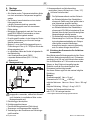
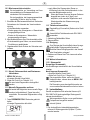
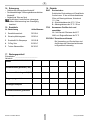
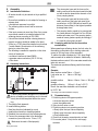
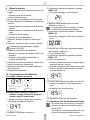
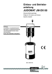
KaltecSoft KS10S
Einbauanleitung • Installation instruction • Istruzioni di montaggio
+
Regeneration
Menu / OK
EB-KS10S Rev. D
KaltecSoft
Anleitung zum späteren Gebrauch aufbewahren!
Keep instructions for later use!
Conservare le istruzioni per uso successivo!
Enthärtungsgerät KaltecSoft
Softener KaltecSoft
Addolcitore d'acqua KaltecSoft
D
1.
Sicherheitshinweise
Desinfektion
Das Enthärtungsgerät ist mit einer Desinfektionseinheit ausgerüstet, die bei jeder Regeneration alle trinkwasserführenden Teile des Enthärtungsgeräts
desinfiziert.
1. Beachten Sie die Einbauanleitung.
2. Benutzen Sie das Gerät
• bestimmungsgemäß
• in einwandfreiem Zustand
• sicherheits- und gefahrenbewusst.
3. Beachten Sie, dass das Gerät ausschließlich für
den in dieser Einbauanleitung genannten Verwendungsbereich bestimmt ist. Eine andere oder
darüber hinausgehende Benutzung gilt als nicht
bestimmungsgemäß.
4. Beachten Sie, dass alle Montage-, Inbetriebnahme,
Wartungs- und Justagearbeiten nur durch autorisierte Fachkräfte ausgeführt werden dürfen.
5. Lassen Sie Störungen, welche die Sicherheit beeinträchtigen können, sofort beseitigen.
6. Fehler in der Installation, Wartung und im Betrieb
lassen alle Garantieansprüche erlöschen.
Beachten Sie als Inhaber oder Betreiber der
Anlage die Anzeige- und Hinweispflichten, die
sich aus §§ 13, 16 und 21 TrinkwV:2001 ergeben.
2.
4.
1-3 Familienhaus
KS10S-60
3-8 Familienhaus
5.
Verwendung
Trinkwasser
Umgebungstemperatur 2-40°C
Nenndruck
6.
PN 10
Technische Daten
Wassertemperatur
1-40°C
Betriebsdruck
1,3 - 8,5 bar
Durchfluss
max. 3,2 m3/h
Druckverlust bei max. Durchfluss 2,0 bar
Anwendung
Netzspannung (ext. Trafo)
230 V / 50 Hz
Schutzkleinspannung
24 V / 50 Hz
Leistungsaufnahme
2W
Schutzklasse
IP 22
Anschlussgröße
1" AG
Anschluss Abwasser
1/2" Schlauchtülle
Die Anlage ist für den Betrieb mit Salztabletten konzipiert (nach DIN EN 19604).
Funktionsbeschreibung
7.
Das Enthärtungsgerät wird über einen hochmodernen
Mikroprozessor gesteuert. Mit dem integrierten
Verbrauchsmengenzähler errechnet der Mikroprozessor die individuellen Verbrauchsgewohnheiten und
die daraus resultierende Restkapazität, sowie den
optimalen Zeitpunkt der Regeneration.
Regeneration
Die Regeneration erfolgt in einem 4-Tage Intervall d.h.
spätestens 4 Tage nach der letzten Regeneration wird
die nächste Regeneration ausgelöst (unabhängig vom
Wasserverbrauch).
Wenn 97 % der errechneten Kapazität erreicht sind,
wird unabhängig vom 4-Tage Intervall eine Regeneration ausgelöst. Während der Regeneration kann unbehandeltes Wasser entnommen werden.
MU1H-1417GE23 R0709
KS10S-30
Medium
Das Enthärtungsgerät KaltecSoft KS10S dient der
Enthärtung bzw. Teilenthärtung von Trinkwasser.
Durch den Einsatz eines Enthärtungsgeräts werden
Funktionsstörungen und Schäden durch Kalk in
wasserführenden Leitungen und daran angeschlossenen Apparaten bzw. Armaturen vermindert bzw.
ausgeschlossen. Ein Rückfluss von behandelten
Trinkwasser ist durch einen im Geräteeingang integrierten Rückflussverhinderer nicht möglich.
3.
Varianten
Lieferumfang
Das Enthärtungsgerät besteht aus:
• Gehäuse
• Mikroprozessor
• Bedienfeld mit Statusanzeige
• Flasche mit monodispersem Ionentauscherharz
• Bypassventil mit integriertem Verschneideventil
• Externer Trafo
• Desinfektionseinheit
• Drehtellerventil
• Wellrohranschlussschläuche
• Gesamthärtemessbesteck
2
Honeywell GmbH
D
8.
Montage
4. Abwasserschlauch an Ablaufanschluss
anschließen (Innen-ø Schlauch min. 13mm, 1/2").
Auf freien Auslauf achten!
8.1 Einbauhinweise
• Alle Arbeiten an der Trinkwasserinstallation dürfen
nur durch autorisiertes Fachpersonal ausgeführt
werden
• Der Einbauort muss frostsicher und vor starker
Hitze geschützt sein
o direkte Sonneneinstrahlung vermeiden
• Das Enthärtungsgerät muss auf einer ebenen
Fläche stehen
• Beträgt der Eingangsdruck mehr als 5 bar muss
gemäß DIN 1988 ein Druckminderer vor dem
Enthärtungsgerät eingebaut werden!
• Es sollte geprüft werden, ob der Anlage ein Dosiergerät zur Verminderung von Korrosion nachgeschaltet werden muss
• Maximal 1 m vor dem Enthärtungsgerät muss in
Fließrichtung ein Filter (z. B. F76S) zum Schutz der
Anlage eingebaut sein.
• In unmittelbarer Nähe des Geräts ist folgendes für
den Betrieb nötig:
o ein Kanalanschluss (mind. DN50)
o separater Netzanschluss (230 V / 50 Hz)
o Bodenablauf
8.2 Montageanleitung
min. 20 mm
• Der Spülwasserschlauch und der Schlauch
am Sicherheitsüberlauf des Solebehälters
müssen mit Gefälle zum Kanal geführt oder in
eine Hebeanlage eingeführt werden.
• Der Spülwasserschlauch und der Schlauch
am Sicherheitsüberlauf des Solebehälters
müssen nach DIN 1988 mit mindestens 20 mm
Abstand (freier Auslauf) zum höchstmöglichen
Abwasserspiegel befestigt werden.
• Die Hebeanlage muss mindestens für eine
Wassermenge von 2 m³/h bzw. 35l/min ausgelegt und salzwasserbeständig sein. Entsprechend größer muss die Hebeanlage
dimensioniert werden, wenn sie gleichzeitig
auch für andere Anlagen benutzt wird.
8.3 Einhaltung des Grenzwertes für die Natriumkonzentration
Beim Betrieb eines Enthärtungsgeräts darf der Grenzwert für die Natriumkonzentration (nach Trinkwasserverordnung) von 200 mg/l nicht überschritten werden.
Um die Wasserhärte um 1°dH zu senken muss dem
Wasser ca. 8mg/l Natrium hinzugefügt werden.
Zusätzlich muss der Grundnatriumgehalt* des
Rohwassers berücksichtigt werden.
Aus diesen Werten ergibt sich die maximal mögliche
Enthärtung.
Beispiel:
Grundnatriumgehalt* Naist = 10 mg/l
Grenzwert nach TVO Namax = 200 mg/l
mögliche Natriumzu- Nazusatz = Namax - Naist = 190 mg/l
gabe
mögliche Enthärtung 190 mg/l ÷ 8 mg/l = 23,75
Ergebnis: die Rohwasserhärte kann um
max. 23,75 °dH verringert werden.
Um unwiderrufliche Beschädigungen am Enthärtungsgerät zu vermeiden, müssen alle Schweißund Lötarbeiten in unmittelbarer Nähe vor der
Montage beendet sein!
1. Rohrleitung gut durchspülen
2. Enthärtungsgerät einbauen
• Durchflussrichtung beachten (Pfeilrichtung)
• Spannungs- und biegemomentfrei einbauen
3. Verbindung zu den Anschlüssen am Enthärtungsgerät herstellen
Honeywell GmbH
* nach Angaben des Wasserversorgungsunternehmens
3
MU1H-1417GE23 R0709
D
9.
Inbetriebnahme
o Anzeige Härte blinkt
1. Verschneideeinrichtung in Bypass-Stellung bringen
o die beiden äußeren Ventile schließen
o das mittlere Ventil öffnen
2. Absperrarmatur eingangsseitig öffnen
3. Verschneideeinrichtung in Betriebs-Stellung
bringen
o eingangsseitiges Ventil langsam vollständig
öffnen
o ausgangsseitiges Ventil langsam vollständig
öffnen
o mittleres Ventil schließen
4. Wasseranschlüsse auf Dichtigkeit überprüfen
5. Wasser (ca. 1 Liter) in Salzvorratsbehälter füllen
6. Tablettensalz in den Salzvorratsbehälter füllen
Ausschließlich Tablettensalz nach DIN 19604
verwenden.
7. Trafo mit Gerät verbinden
o Abdeckung Salzbehälter und Haube abnehmen
o Kabelschuhe des Trafos in Steuerung einstecken
8. Haube und Abdeckung wieder aufsetzen, das
Kabel dabei nach hinten aus dem Gerät führen
9. Enthärtungsgerät über den Trafo mit der Netzspannung verbinden
10.Enthärtungsgerät programmieren
HÄRTE
4. Rohwasserhärte durch Drücken von + bzw. einstellen
Die Rohwasserhärte kann beim Wasserversorger erfragt werden.
5. Mit MENU / OK bestätigen
o Anzeige Regenerationszeit blinkt
REGENERATION
ZEIT
6. Gewünschte Uhrzeit für den Start der Regeneration
durch Drücken von + bzw. - einstellen
o empfohlene Uhrzeit 2:00
7. Mit MENU / OK bestätigen
8. Regeneration starten
o Taste Regeneration 5 sec gedrückt halten
o Anzeige Regeneration aktiv blinkt
o Uhrzeit wird während Regenerationsvorgang im
Display angezeigt
10. Enthärtungsgerät programmieren
10.1 Display und Bedientasten
REGENERATION AKTIV
9. Nach Ende Regeneration (Dauer ca. 45 min)
o Anzeige Regeneration aktiv erlischt.
o Uhrzeit steht im Display
AKTUELLE ZEIT
REGENERATION
MENU / OK
10.2 Grundeinstellung zur Inbetriebnahme Uhrzeit, Rohwasserhärte und Regenerationszeit
1. Anschluss an die Stromversorgung besteht
o Anzeige Aktuelle Uhrzeit blinkt
10.Das Gerät ist betriebsbereit
AKTUELLE ZEIT
2. Uhrzeit durch Drücken von + bzw. - einstellen
3. Mit MENU / OK bestätigen
Honeywell GmbH
4
MU1H-1417GE23 R0709
D
10.3 Mischwasserhärte einstellen
Es wird empfohlen, zur Vermeidung von Korrosionsschäden eine Restwasserhärte von
mindestens 8°dH einzustellen.
Es wird empfohlen, die Ausgangswasserhärte
regelmäßig (2 Mal im Jahr) zu prüfen.
1. Einstellen der Mischwasserhärte durch Drehen der
Schraube an der Unterseite der Verschneideeinrichtung
o Schraubendreher verwenden
o Drehen gegen den Uhrzeigersinn = Wasserhärte
ausgangsseitig erhöhen
o Drehen im Uhrzeigersinn = Wasserhärte
ausgangsseitig verringern
2. Mischwasserhärte an einer Entnahmestelle prüfen
o Entnahmestelle ganz öffnen, um ausreichenden
Durchfluss zu gewährleisten
3. Gegebenenfalls durch Drehen der Schraube nachjustieren
o nach Ablauf der Regeneration (Dauer ca.
45 Minuten) kehrt das Gerät automatisch in den
normalen Betriebsmodus zurück
Wenn das Wasser für einen längeren Zeitraum
abgestellt war (mehr als 4 Tage), wird
empfohlen, eine manuelle Regenration nach
Wiederherstellen der Wasserversorgung
durchzuführen.
11.3 Tablettensalz nachfüllen
Regelmäßig (z.B. monatlich) Salzvorrat im Gerät
prüfen
Ausschließlich Tablettensalz nach DIN 19604
verwenden.
1. Abdeckung Salzbehälter öffnen
2. Salz nachfüllen
11.4 Reinigung
Zum Reinigen der Kunststoffteile keine lösungsmittelhaltigen Reinigungsmittel benutzen!
Es dürfen keine Reinigungsmittel in die Umwelt
oder Kanalisation gelangen!
1. Gehäuse mit Wasser und Tuch innen und außen
reinigen
11.5 Weitere Informationen
11.5.1 Stromausfall:
Kurzzeitiger Stromausfall:
Alle Einstellungen einschließlich der Uhrzeit bleiben
erhalten
Nach längerem Stromausfall:
o Anzeige Aktuelle Uhrzeit blinkt
o Weiter mit Punkt 2 bis 11 Kapitel 10.2
Die eingestellten Werte, außer der Uhrzeit,
bleiben erhalten, müssen aber mit MENU / OK
bestätigt werden.
Die Reneration muss durchgeführt werden um
zum normalen Betriebsmodus zurück zu kehren.
11. Betrieb
11.1 Uhrzeit, Rohwasserhärte und Restwasserhärte ändern
1. MENU / OK drücken
o Anzeige Aktuelle Uhrzeit blinkt
2. Weiter mit Punkt 2 bis 7 Kapitel 10.2
Es muss keine Regeneration durchgeführt
werden.
11.2 Manuelle Regeneration auslösen
Es besteht die Möglichkeit eine manuelle Regeneration (außerhalb des 4-Tages Intervalls)
auszulösen. Die manuelle Regeneration erfolgt
sofort.
1. Taste REGENERATION 5 Sekunden gedrückt
halten
o Anzeige Regeneration aktiv blinkt
12. Instandhaltung
Gemäß europäischer und nationaler Normen (z.B.
DIN 1988 Teil 8) sind regelmäßige Wartungsmaßnahmen durchzuführen.
Wartungsarbeiten dürfen nur von qualifiziertem
Fachpersonal ausgeführt werden!
Intervall: jährlich
1. Die durchgeführten Instandhaltungsarbeiten
müssen im Wartungsprotokoll (Kapitel 17) dokumentiert werden.
REGENERATION AKTIV
MU1H-1417GE23 R0709
5
Honeywell GmbH
D
Folgende Wartungsarbeiten müssen durchgeführt
werden:
12.1 Desinfektionseinheit austauschen
Die Desinfektionseinheit hat eine Lebensdauer
von 100 Regeneration (ca.1 Jahr) und muss
danach erneuert werden.
Wartungsarbeiten dürfen nur von qualifiziertem
Fachpersonal ausgeführt werden!
Bitte wenden Sie sich an Ihren Fachinstallateur
oder den technischen Kundendienst von
Honeywell (Tel. 0 18 01 - 46 63 88)
Zum Austausch wird die Desinfektionseinheit
DE10S-A benötigt.
12.2 Inspektion Saugpumpe
Wartungsarbeiten dürfen nur von qualifiziertem
Fachpersonal ausgeführt werden!
Bitte wenden Sie sich an Ihren Fachinstallateur
oder den technischen Kundendienst von
Honeywell (Tel. 0 18 01 - 46 63 88)
Zur Wartung der Saugpumpe wird das
Wartungsset EK10S-B benötigt.
12.3 Inspektion Dichtungssatz Steuerkopf
Wartungsarbeiten dürfen nur von qualifiziertem
Fachpersonal ausgeführt werden!
Bitte wenden Sie sich an Ihren Fachinstallateur
oder den technischen Kundendienst von
Honeywell (Tel. 0 18 01 - 46 63 88)
Zum Austausch wird der Steuerkopfdichtungssatz EK10S-A benötigt.
13. Störungen / Fehlersuche
Störung
Keine Wasserversorgung zum
Gerät
Gerät regeneriert nicht
Ursache
Absperrarmatur in Umgehungsleitung
(Bypass) nicht ganz oder gar nicht
geöffnet.
Rohrleitung der Trinkwasserversorgung verkalkt oder verstopft
Durchflussmesser defekt
Keine Anzeige im Display
Interne elektrische Verkabelung
defekt
Anschlussleitungen falsch angeschlossen
Drehtellerventil defekt
Stromversorgung unterbrochen
Drehtellerventil defekt
Falsche Uhrzeit wird im Display Gerät hatte Stromausfall
angezeigt
Unzureichende Funktion
Gerät nicht entlüftet
Vorratsbehälter fast oder ganz leer
Verschneidung falsch eingestellt
*
Behebung
Absperrarmatur vollständig öffnen
Rohrleitung reinigen oder ersetzen
Durchflussmesser überprüfen ggf.
ersetzen (KD*)
Interne elektrische Verkabelung überprüfen (KD*)
Anschlussleitungen richtig anschließen
Technische Kundenberatung anrufen
Stromversorgung überprüfen (Netzstecker, Sicherung)
Technische Kundenberatung anrufen
Uhrzeit einstellen
Gerät entlüften
Füllstand Salz überprüfen
Verschneideventil und Mischungsverhältnis überprüfen
Steuerventil verschmutzt oder defekt Technische Kundenberatung anrufen
KD = Kundendienst Tel. 0 18 01 - 46 63 88
Honeywell GmbH
6
MU1H-1417GE23 R0709
D
14. Entsorgung
16. Zubehör
• Gehäuse aus hochwertigem Kunststoff
• Druckbeaufschlagte Teile aus glasfaserverstärktem
Kunststoff
• Soleberührte Teile aus Noryl
Die örtlichen Vorschriften zur ordnungsgemäßen Abfallverwertung bzw. Beseitigung
beachten!
D06F
15. Ersatzteile
F76S
Nr. Bezeichnung
Artikel-Nummer
1 Desinfektionseinheit
DE10S-A
2 Steuerkopfdichtungssatz
EK10S-A
3 Ersatzteilkit für Solepumpe
EK10S-B
4 O-Ring Satz
EK10S-C
5 Turbine Wasserzähler
EK10S-D
Druckminderer
Schallschutz-Druckminderer mit Einstellskala
Vordruck max. 16 bar mit Klarsichtsiebtasse,
25 bar mit Messingsiebtasse, Hinterdruck
1,5 - 6 bar
A = Klarsichtsiebtasse bis 40°C / 16 bar
B = Messingsiebtasse bis 70°C / 25 bar
Hauswasser-Feinfilter rück- und
ausspülbar
AA = mit Klarsicht-Filtertasse bis 40°C
AAM = mit Rotgussfiltertasse bis 70°C
OFV10S-A Überströmventileinsatz
Bei Verwendung von Druckspülern wird
die Montage des Überstromventileinsatz
im Bypassventil notwendig.
17. Wartungsprotokoll
Einbaudatum: _________________________
Netzdruck: _________________________
Datum:
Rohwasserhärte gemessen (°dH)
Mischwasserhärte eingestellt (°dH)
Saugpumpe gewartet
Dichtungen überprüft
Desinfektionseinheit gewechselt
Bemerkungen:
MU1H-1417GE23 R0709
7
Honeywell GmbH
GB
1.
Safety Guidelines
Disinfection
The softening device is equipped with a disinfection
unit that disinfects all drinking water porting part of the
softening device during each regeneration.
1. Follow the installation instructions.
2. Use the appliance
• according to its intended use
• in good condition
• with due regard to safety and risk of danger.
3. Note that the appliance is exclusively for use in the
applications detailed in these installation instructions. Any other use will not be considered to comply
with requirements and would invalidate the
warranty.
4. Please take note that any assembly, commissioning, servicing and adjustment work may only be
carried out by authorized persons.
5. Immediately rectify any malfunctions which may
influence safety.
6. Faults made during installation, maintenance or
operation make all claims for warranty void.
Please note as owner and operator of the plant
the notification and information obligations that
result from sections 13, 16, and 21 of the drinking
water ordinance:2001.
Medium
Drinking water
Ambient air temperature 2-40 °C
Nominal pressure
PN 10
2.
Micro fuse
24 V / 50 Hz
Power consumption
2W
Protective class
IP 22
Connection size
1" AG
Connection water output
1/2" hose nozzle
4.
1-3 family dwelling
KS10S-60
3-8 family dwelling
6.
Application
Technical data
Water temperature
1-40 °C
Operating pressure
1.3 - 8.5 bar
Flow rate
max. 3.2 m3/h
Pressure loss during max. flow
rate
2.0 bar
Mains voltage (ext. transformer) 230 V / 50 Hz
Application
The plant is designed for operation with salt tablets
(acc. DIN EN 19604).
Functional description
7.
The softening device is controlled by a highly modern
microprocessor. Using the integrated consumption
counter the microprocessor calculates the individual
consumption characteristics and the remaining capacities resulting thereof as well as the optimal time for the
regeneration.
Regeneration
The regeneration is done in 4-day intervals, i.e. at the
latest 4 days after the last regeneration the next regeneration is initiated (independent of the water
consumption).
If 97 % of the calculated capacity has been reached, a
regeneration is initiated independently of the 4-day
interval. During the regeneration, untreated water can
be taken out.
MU1H-1417GE23 R07009
KS10S-30
5.
The softening device KaltecSoft KS10S serves to
soften of partially soften drinking water. Use of a softening device reduces or excludes malfunctions and
damages by limescale in water-bearing pipes and
apparatuses and valves connected to them. A backflow of treated drinking water is not possible due to a
backflow preventer installed in the device input.
3.
Options
Scope of delivery
The softening device consists of:
• Housing
• Microprocessor
• Control panel with status indicator
• Bottle with monodisperse ion exchanger
• Bypass valve with integrated diluting valve
• External transformer
• Disinfection unit
• Rotary disc valve
• Corrugated pipe connection hoses
• Total hardness measuring instrument
8
Honeywell GmbH
GB
8.
Assembly
• The rinse water hose and the hose on the
safety overflow of the brine tank need to be laid
out with a decline towards the channel or fed
into a pumping station.
• The rinse water hose and the hose on the
safety overflow of the brine tank need to be
mounted acc. to DIN 1988 with at least 20 mm
distance (free outflow) to the highest possible
drainage water level.
• The pumping station needs to be constructed
for a water amount of at least 2 m³/h or 35l/min
and be salt-water proof. The pumping station
needs to have a greater capacity accordingly if
it is used for other plants as well.
8.3 Complying with the limit for the sodium
concentration
When operating a softening device, the limit value for
the sodium concentration (acc. drinking water ordinance) of 200 mg/l may not be exceeded.
To reduce the water hardness by 1°dH, about 8mg/l
sodium needs to be added to the water. Additionally,
the basic sodium content* of the raw water needs to be
taken into account.
The maximum possible softening results from these
values.
Example:
Basic sodium content*Naact. = 10 mg/l
Limit value acc. to
Namax = 200 mg/l
TVO
possible sodium
Nadose = Namax - Naact. = 190 mg/l
dosage
possible softening
190 mg/l ÷ 8 mg/l = 23.75
Result: the raw water hardness can be reduced
by 23.75 °dH.
min. 20 mm
8.1 Installations Guidelines
• All works should only be carried out by a qualified
person
• Ensure that installation is not subject to freezing or
extreme heat
o Avoid direct exposure to sunlight.
• The softening device should rest on an even
surface.
• If the input pressure is more than 5 bar, then a pressure reducer needs to be installed ahead of the
softening device according to DIN 1988.
• It should be checked whether a dosing device to
prevent corrosion should be added to the plant.
• A filter (e.g. F762) should be installed no more than
1 metre ahead in flow direction of the softening
device to protect the plant.
• The following is needed for operation in the close
vicinity of the device:
o a channel interface (at least DN50)
o separate mains connection (230 V / 50 Hz)
o Floor drain
8.2 Assembly instructions
* according to the water distribution company
To avoid irreplaceable damages on the softening
device, all welding and soldering work in the near
vicinity should be completed before the mounting.
1. Thoroughly flush pipework
2. Install softening device
• Note flow direction (indicated by arrow)
• Install without tension or bending stresses
3. Establish the connections to the softening device
4. Connect the sewerage tube to the discharge
connection (inner tube ø min. 13 mm, 1/2")
Make sure the seal is fitted properly!
Honeywell GmbH
9.
Commissioning
1. Put diluting device into bypass position
o close the two outer valves
o open the middle valve
2. Open shut-off valve on inlet
3. Put diluting device into operating position
o Slowly open the input valve completely
o Slowly open the output valve completely
o Close middle valve
4. Check that the water connections do not leak
5. Pour water (about 1 litre) into the salt supply
container
9
MU1H-1417GE23 R07009
GB
6. Pour salt tablets into the salt supply container
Use only salt tablets acc. DIN 19604.
o Recommended time 2:00
7. Confirm with MENU / OK
8. Starting regeneration
o Press the Regeneration key for 5 seconds
o Display Regeneration active flashes
o The time is displayed in the display during the
regeneration process
7. Connect transformer to the device
o Remove cover to the salt container and hood
o Plug the cable shoes of the transformer into the
controller
8. Replace hood and cover, guide the cable out of the
back of the device
9. Connect the softening device to the mains via the
transformer
10.Programming the softening device
REGENERATION AKTIV
9. After the end of the regeneration (duration 45
minutes)
o Display Regeneration active goes out.
o The time is displayed
10. Programming the softening device
10.1 Display and operating keys
AKTUELLE ZEIT
REGENERATION
10.The device is ready for operation
10.3 Setting the mix water hardness
It is recommended to set a residual water hardness of at least 8°dH to avoid corrosion
damages.
It is recommended to check the output water
hardness regularly (2 times a year).
1. Setting the mix water hardness by turning the screw
at the base of the diluting device
o Use screwdriver
o Turn counter-clockwise = increase water hardness on output side
o Turn clockwise = decrease water hardness on
output side
2. Check the mix water hardness at a tapping point
o Open tapping point completely to ensure sufficient
flow
3. Readjust by turning the screw if necessary
MENU / OK
10.2 Basic settings for commissioning - time, raw
water hardness and regeneration time
1. There is a connection to the power supply
o Display Current time flashes
AKTUELLE ZEIT
2. Set the time by pressing + or 3. Confirm with MENU / OK
o Display Hardness flashes
HÄRTE
4. Set the raw water hardness by pressing + or The hardness of the raw water can be inquired
from the water distribution company.
5. Confirm with MENU / OK
o Display Regeneration time flashes
REGENERATION
ZEIT
6. Set the desired time for the regeneration by pressing + or Honeywell GmbH
10
MU1H-1417GE23 R07009
GB
11. Operation
o Continue with point 2 to 11 chapter 10.2
The settings, excluding the time remain intact,
but need to be confirmed with MENU / OK .
The regeneration needs to be carried out to
return to the normal operating mode.
11.1 Changing time raw water hardness and residual water hardness
1. MENU / OK
o Display Current time flashes
2. Continue with point 2 to 7 chapter 10.2
No regeneration needs to be carried out.
12. Maintenance
In compliance with European and national norms (e.g.
DIN 1988 part 8) regular maintenance must be
conducted.
Maintenance work should only be carried out be
qualified staff!
Interval: yearly
11.2 Initiating a manual regeneration
It is possible to initiate a manual regeneration
(within the 4-day interval). The manual regeneration is carried out immediately.
1. Press the REGENERATION key for 5 seconds
o Display Regeneration active flashes
1. The completed maintenance work needs to be
documents in the maintenance log (chapter 17).
The following maintenance work needs to be carried
out:
12.1 Replace disinfection unit
The disinfection unit has a service life of 100
regenerations (about 1 year) and needs to be
replaced after that.
Maintenance work should only be carried out be
qualified staff!
Please contact your professional plumber or
Honeywell's technical customer services (tel. 0
18 01 - 46 63 88)
The disinfection unit DE10S-A is needed for the
replacement.
12.2 Inspection suction pump
Maintenance work should only be carried out be
qualified staff!
Please contact your professional plumber or
Honeywell's technical customer services (tel. 0
18 01 - 46 63 88)
The maintenance kit EK10S-B is needed for
maintenance of the suction pump.
12.3 Inspection seal kit for controller head
Maintenance work should only be carried out be
qualified staff!
Please contact your professional plumber or
Honeywell's technical customer services (tel. 0
18 01 - 46 63 88)
The controller head seal kit EK10S-A is needed
for the replacement.
REGENERATION AKTIV
o After completion of the regeneration (duration
about 45 minutes), the device returns automatically to the normal operating mode
If the water was switched off for a longer period
(more than 4 days), it is recommended to carry
out a manual regeneration after re-establishing
the water supply.
11.3 Refilling salt tablets
Check the salt supply (e.g. monthly) in the device
Use only salt tablets acc. DIN 19604.
1. Open the salt container cover
2. Refill salt
11.4 Cleaning
Do not use cleaning agents that contain solvents
when cleaning the plastic parts!
Detergents must not be allowed to enter the
environment or the sewerage system!
1. Clean the housing with water and a cloth inside and
out
11.5 Further information
11.5.1 Power Failure:
Brief power failure:
All settings including the time remain intact
After longer power outage:
o Display Current time flashes
MU1H-1417GE23 R07009
11
Honeywell GmbH
GB
13. Troubleshooting
Problem
Cause
Remedy
No water supply to the device
Shut-off device in the bypass is not
open or only partially open
Open shut off valve fully
Pipework of the drinking water supply Clean or replace the pipework
is calcified or blocked
Device does not regenerate
Flow meter is defective
Check and, if necessary, replace the
flow meter (CS*)
Internal electric cabling is defective
Check internal electric cabling (CS*)
Wrong connection of connecting hoses Connect the flexible connection lines
correctly
Nothing is displayed
Rotary disc valve defective
Call Technical Customer Service
Power supply has been interrupted
Check power suppy (mains plug, fuse)
Rotary disc valve defective
Call Technical Customer Service
Incorrect time is displayed
Power failure occurred
Set the time
Insufficient function
Device not deaerated
Deaerate device
Storage tank is almost or completely Check salt level
empty
Blending has been set incorrectly
*
Control valve is contaminated or
defective
CS = Customer services tel. 0 18 01 - 46 63 88
Check blending valve and mixing ratio
Call Technical Customer Service
14. Disposal
16. Accessories
• High quality synthetic material housing
• All components subject to pressure in glass-fibrereinforced plastics
• All components to brine in Noryl
Observe the local requirements regarding
correct waste recycling/disposal!
D06F
Noise protected pressure reducing valve
with setting scale. Maximum inlet pressure
16 bar, with brass filter bowl 25 bar, outlet
pressure range 1.5 - 6.0 bar
A = With clear filter bowl up to 40 °C / 16 bar
B = With brass filter bowl up to 70 °C / 25 bar
15. Spare Parts
No. Description
Part No.
1 Disinfection unit
DE10S-A
2 Controller head seal kit
EK10S-A
3 Spare part kit for brine pump
EK10S-B
4 O-ring set
EK10S-C
5 Turbine water counter
EK10S-D
Honeywell GmbH
Pressure reducing valve
F76S
Fine filter, reverse rinsable
AA = With clear filter bowl
AAM= With red bronze filter bowl
OFV10S-A Bypass valve insert
if a pressure scourer is applicated it is
neccessary to fit a bypass valve insert into
the bypass valve.
12
MU1H-1417GE23 R07009
GB
17. Maintenance log
Installation date: _________________________
Network pressure: _________________________
Date:
Raw water hardness measured
(°dH)
Mix water hardness set (°dH)
Suction pump maintained
Seals checked
Disinfection unit replaced
Notes:
MU1H-1417GE23 R07009
13
Honeywell GmbH
I
1.
Avvertenze di sicurezza
Disinfezione
L'addolcitore è dotato di un'unità disinfettante che ad
ogni processo di rigenerazione disinfetta tutti i componenti dell'apparecchio a contatto con l'acqua potabile.
1. Rispettare le istruzioni di montaggio.
2. Utilizzare l'apparecchio
• secondo la destinazione d'uso
• in uno stato perfetto
• in modo sicuro e consapevoli dei pericoli connessi
3. Si prega di considerare che l'apparecchio è realizzato esclusivamente per il settore d'impiego riportato nelle presenti istruzioni d'uso. Un uso differente
o diverso da quello previsto è da considerarsi improprio.
4. Osservare che tutti i lavori di montaggio, di messa in
funzione, di manutenzione e di regolazione devono
essere eseguiti soltanto da tecnici specializzati e
autorizzati.
5. I guasti che potrebbero compromettere la sicurezza
devono essere risolti immediatamente.
6. Errori di installazione, manutenzione e uso fanno
decadere qualsiasi diritto alla garanzia.
In qualità di proprietario o gestore dell'impianto,
osservare gli obblighi di segnalazione e avviso
risultanti da §§ 13, 16 e 21 TrinkwV:2001.
2.
4.
Varianti
KS10S-30
Casa da 1-3 famiglie
KS10S-60
Casa da 3-8 famiglie
5.
Uso
Mezzo
acqua potabile
Temperatura ambiente 2-40°C
Pressione nominale
6.
PN 10
Dati tecnici
Temperatura dell'acqua
1-40°C
Pressione di esercizio
1,3 - 8,5 bar
Portata
max. 3,2 m3/h
Perdita di pressione alla max.
portata
2,0 bar
Tensione di rete (trasform. est.) 230 V / 50 Hz
Uso
Bassa tensione
24 V / 50 Hz
Potenza assorbita
2W
L'addolcitore d'acqua KaltecSoft KS10S serve per
addolcire e/o addolcire parzialmente l'acqua potabile.
Grazie all'impiego di questo addolcitore è possibile
ridurre o escludere eventuali malfunzionamenti e
danni causati dal calcare che si deposita nelle tubazioni e negli apparecchi/raccordi ad esse collegati. Un
riflusso dell'acqua potabile trattata viene impedito da
una valvola antiriflusso integrata nell'ingresso
dell'apparecchio.
L'impianto è concepito per funzionare con sale in
pastiglie (secondo DIN EN 19604).
3.
7.
Descrizione del funzionamento
L'addolcitore d'acqua viene comandato da un microprocessore ultra-moderno che, grazie al contatore dei
consumi integrato, calcola le abitudini individuali e la
risultante capacità residua, così come il momento ottimale di rigenerazione.
Rigenerazione
La rigenerazione avviene a intervalli di 4 giorni, ovvero
al massimo 4 giorni dopo l'ultima rigenerazione viene
avviata la rigenerazione successiva (indipendentemente dal consumo di acqua).
Quando viene raggiunto il 97% della capacità calcolata, viene avviata una rigenerazione indipendente
dall'intervallo di 4 giorni. Durante la rigenerazione è
possibile prelevare acqua non trattata.
MU1H-1417GE23 R0709
Classe di protezione
IP 22
Dimensioni attacchi
1" FE
Attacco acqua di scarico
1/2" bocchetta per
tubi flessibili
Fornitura
L'addolcitore d'acqua è costituito da:
• Scatola
• Microprocessore
• Pannello dei comandi con display di stato
• Bombola con resina monodispersa a scambio
ionico
• Valvola di bypass con valvola di miscelazione integrata
• Trasformatore esterno
• Unità disinfettante
• Valvola rotativa
• Flessibili di collegamento per tubi ondulati
• Dotazione di strumenti per misurare la durezza
totale
14
Honeywell GmbH
I
8.
Montaggio
4. Collegare il flessibile di scarico all'attacco di scarico
(ø interno flessibile min. 13mm, 1/2").
Accertarsi che lo scarico sia libero!
8.1 Istruzioni di installazione
• Tutti i lavori sull'impianto di acqua potabile devono
essere eseguiti esclusivamente da parte di personale qualificato e autorizzato
• Il luogo di installazione deve essere protetto dal gelo
e dal calore eccessivo
o Evitare l'esposizione diretta ai raggi solari
• L'addolcitore d'acqua deve poggiare su una superficie piana
• Se la pressione in ingresso è superiore a 5 bar, ai
sensi della norma DIN 1988 è necessario montare
un riduttore di pressione a monte dell'addolcitore!
• Verificare la necessità di collegare a valle dell'impianto un dosatore contro la corrosione
• Per proteggere l'impianto, al massimo a 1 m a
monte dell'addolcitore è necessario montare un
filtro (p.es. F76S) in direzione del flusso.
• Per il funzionamento dell'apparecchio, nelle sue
immediate vicinanze sono necessari:
o un attacco canale (almeno DN50)
o presa di corrente separata (230 V / 50 Hz)
o scarico nel pavimento
8.2 Istruzioni di montaggio
min. 20 mm
• Il tubo flessibile di scarico e il tubo flessibile
collegato alla valvola di troppo pieno del serbatoio di salamoia devono essere posati in
pendenza verso il canale di scarico o introdotti
in un impianto di sollevamento.
• Il tubo flessibile di scarico e il tubo flessibile
collegato alla valvola di troppo pieno del serbatoio di salamoia devono essere fissati secondo
DIN 1988 a una distanza minima di 20 mm
(scarico libero) dal livello d'acqua più alto
possibile.
• L'impianto di sollevamento deve essere configurato almeno per una portata d'acqua di 2 m³/
h (ovvero di 35l/min) ed essere resistente
all'acqua salata. Se viene utilizzato contemporaneamente anche per altri apparecchi,
l'impianto di sollevamento deve essere
sufficientemente dimensionato.
8.3 Rispetto della concentrazione massima di
sodio
Durante il funzionamento dell'addolcitore d'acqua, la
concentrazione di sodio non deve superare la soglia di
200 mg/l (secondo la legge sulle acque potabili).
Per ridurre la durezza dell'acqua di 1°dH è necessario
aggiungere all'acqua circa 8mg/l di sodio. Inoltre
occorre considerare il contenuto di sodio naturale*
dell'acqua non trattata.
Da questi valori risulta il massimo addolcimento possibile.
Esempio:
Contenuto naturale di Naeff = 10 mg/l
sodio*
Soglia prescritta per Namax = 200 mg/l
legge
Possibile aggiunta di Naagg = Namax - Naeff = 190 mg/l
sodio
Addolcimento possi- 190 mg/l ÷ 8 mg/l = 23,75
bile
Risultato: la durezza dell'acqua non trattata può
essere ridotta di max. 23,75 °dH.
Per evitare danni irreparabili all'addolcitore, tutti i
lavori di saldatura e brasatura necessari in prossimità dell'apparecchio devono essere terminati
prima del montaggio!
1. lavare bene la tubazione
2. Montare l'addolcitore d'acqua
• Osservare la direzione di flusso (direzione della
freccia)
• Garantire un montaggio privo di tensioni e flessioni
3. Realizzare il collegamento verso tutti gli attacchi
dell'addolcitore
Honeywell GmbH
* Dati forniti dall'ente di approvvigionamento dell'acqua
15
MU1H-1417GE23 R0709
I
9.
Messa in funzione
3. Confermare la regolazione premendo il pulsante
MENU / OK
o Sul display lampeggia la scritta Durezza
1. Portare il dispositivo di miscelazione in posizione di
bypass
o Chiudere le due valvole esterne
o Aprire la valvola centrale
2. Aprire l'organo di intercettazione sul lato ingresso
3. Portare il dispositivo di miscelazione in posizione di
esercizio
o Aprire lentamente e completamente la valvola lato
ingresso
o Aprire lentamente e completamente la valvola lato
uscita
o Chiudere la valvola centrale
4. Controllare la tenuta degli attacchi
5. Riempire il serbatoio del sale con acqua (circa 1
litro)
6. Riempire il serbatoio del sale con sale in pastiglie
Utilizzare esclusivamente sale in pastiglie
secondo DIN 19604.
7. Collegare il trasformatore all'apparecchio
o Rimuovere il coperchio del serbatoio del sale e la
copertura
o Collegare i capicorda del trasformatore al
comando dell'addolcitore
8. Rimontare la copertura e il coperchio, facendo fuoriuscire il cavo da dietro l'apparecchio
9. Attraverso il trasformatore, collegare l'addolcitore
alla rete elettrica
10.Programmare l'addolcitore
HÄRTE
4. Regolare la durezza dell'acqua non trattata
premendo i pulsanti + o La durezza dell'acqua non trattata può essere
richiesta all'ente di approvvigionamento.
5. Confermare la regolazione premendo il pulsante
MENU / OK
o Sul display lampeggia la scritta Orario di rigenerazione
REGENERATION
ZEIT
6. Regolare l'ora di inizio della rigenerazione desiderata premendo i pulsanti + o o Ora consigliata: 02:00
7. Confermare la regolazione premendo il pulsante
MENU / OK
8. Avviare la rigenerazione
o Premere e mantenere premuto il pulsante Rigenerazione per almeno 5 secondi
o Sul display lampeggia la scritta Rigenerazione attiva
o Durante il processo di rigenerazione, sul display
viene visualizzata l'ora
10. Programmazione dell'addolcitore
10.1 Display e pulsanti di comando
REGENERATION AKTIV
9. Al termine della rigenerazione (durata circa 45 min):
o sul display scompare la scritta Rigenerazione
attiva.
o sul display viene visualizzata l'ora
AKTUELLE ZEIT
REGENERATION
MENU / OK
10.2 Impostazioni di base per la messa in
funzione: orologio, durezza dell'acqua non
trattata e orario di rigenerazione
1. L'apparecchio è stato collegato alla rete elettrica
o Sul display lampeggia la scritta Ora
10.L'apparecchio è pronto al funzionamento
10.3 Regolazione della durezza dell'acqua miscelata
Per evitare danni da corrosione, si consiglia di
impostare una durezza residua dell'acqua di
almeno 8°dH.
Si consiglia di controllare regolarmente (2 volte
all'anno) la durezza dell'acqua di scarico.
AKTUELLE ZEIT
2. Regolare l'ora premendo i pulsanti + o Honeywell GmbH
16
MU1H-1417GE23 R0709
I
1. Regolare la durezza dell'acqua miscelata ruotando
la vite posta nella parte inferiore dell'organo di
miscelazione
o Utilizzare un cacciavite
o Rotazione in senso antiorario = aumento della
durezza dell'acqua lato uscita
o Rotazione in senso orario = riduzione della
durezza dell'acqua lato uscita
2. Controllare la durezza dell'acqua miscelata in un
punto di prelievo
o Aprire completamente il punto di prelievo, in modo
da garantire una sufficiente portata
3. Eventualmente correggere la durezza intervenendo
sulla vite
alla modalità di funzionamento normale
Se l'alimentazione dell'acqua è stata interrotta
per un lungo periodo di tempo (più di 4 giorni),
si consiglia di effettuare una rigenerazione
manuale dopo che è stata ripristinata l'alimentazione.
11.3 Rifornimento del sale in pastiglie
Controllare regolarmente (p.es. una volta al
mese) il contenuto di sale nell'apparecchio
Utilizzare esclusivamente sale in pastiglie
secondo DIN 19604.
1. Aprire la coperchio del serbatoio del sale
2. Riempire il sale nel serbatoio
11.4 Pulizia
Per pulire le parti in plastica, non utilizzare detergenti contenenti solventi!
Nell'ambiente o nella canalizzazione è necessario che non venga scaricato alcun detergente!
1. Pulire internamente ed esternamente la scatola
utilizzando acqua e un panno
11.5 Ulteriori informazioni
11.5.1 Caduta di corrente
Caduta di corrente di breve durata
Tutte le impostazioni, ora inclusa, rimangono in essere
Caduta di corrente di lunga durata
o Sul display lampeggia la scritta Ora
o Continuare con i punti da 2 a 11 specificati nel
capitolo 10.2
I valori impostati, esclusa l'ora, rimangono in
essere, ma devono essere confermati con il
pulsante MENU / OK.
È necessario avviare una rigenerazione per
tornare alla modalità di funzionamento normale.
11. Uso
11.1 Modifica dell'ora, della durezza dell'acqua
non trattata e della durezza residua dell'acqua
1. Premere il pulsante MENU / OK
o Sul display lampeggia la scritta Ora
2. Continuare con i punti da 2 a 7 specificati nel capitolo 10.2
Non è necessario effettuare una rigenerazione.
11.2 Rigenerazione manuale
Esiste la possibilità di effettuare una rigenerazione manuale (al di fuori dell'intervallo di 4
giorni). La rigenerazione manuale viene avviata
immediatamente.
1. Premere e mantenere premuto il pulsante RIGENERAZIONE per almeno 5 secondi
o Sul display lampeggia la scritta Rigenerazione
attiva
12. Manutenzione
Ai sensi delle norme europee e nazionali (p.es.
DIN 1988 parte 8) è necessario garantire i regolari
interventi di manutenzione.
I lavori di manutenzione possono essere
eseguiti esclusivamente da parte di personale
qualificato!
Frequenza: una volta all'anno
REGENERATION AKTIV
1. I lavori di manutenzione eseguiti devono essere documentati sul libretto di manutenzione (capitolo 17).
È necessario effettuare i seguenti lavori di manutenzione:
o Al termine della rigenerazione (durata circa
45 minuti), l'apparecchio torna automaticamente
MU1H-1417GE23 R0709
17
Honeywell GmbH
I
12.1 Sostituzione dell'unità disinfettante
L'unità disinfettante ha una durata di 100 rigenerazioni (circa 1 anno) e deve essere sostituita
dopo questo periodo.
I lavori di manutenzione possono essere
eseguiti esclusivamente da parte di personale
qualificato!
Rivolgersi al proprio installatore di fiducia o al
servizio clienti della Honeywell (tel. 0 18 01 - 46
63 88)
Per la sostituzione è necessaria l'unità disinfettante DE10S-A.
12.2 Ispezione pompa aspirante
I lavori di manutenzione possono essere eseguiti
esclusivamente da parte di personale qualificato!
Rivolgersi al proprio installatore di fiducia o al
servizio clienti della Honeywell (tel. 0 18 01 - 46
63 88)
Per la manutenzione della pompa aspirante è
necessario il kit di manutenzione EK10S-B.
12.3 Ispezione del kit di guarnizioni della testata
I lavori di manutenzione possono essere eseguiti
esclusivamente da parte di personale qualificato!
Rivolgersi al proprio installatore di fiducia o al
servizio clienti della Honeywell (tel. 0 18 01 - 46
63 88)
Per la sostituzione è necessario il kit di guarnizioni della testata EK10S-A.
13. Guasti / Ricerca guasti
Guasto
Causa
Risoluzione
Nessuna alimentazione di acqua L'organo di intercettazione nella tuba- Aprire completamente l'organo di interverso l'apparecchio
zione di bypass non è completamente cettazione
aperto o è chiuso.
La tubazione di alimentazione
Pulire o sostituire la tubazione
dell'acqua potabile è incrostata di
calcare o intasata
L'apparecchio non effettua la rige- Il misuratore di portata è difettoso
Controllare il misuratore di portata ed
nerazione
eventualmente sostituirlo (SC*)
Il cablaggio elettrico interno è difettoso Controllare il cablaggio elettrico interno
(SC*)
Le tubazioni di collegamento non sono Collegare correttamente le tubazioni
collegate correttamente
La valvola rotativa è difettosa
Contattare il servizio di assistenza
clienti
Nessun visualizzazione sul
L'alimentazione elettrica è interrotta Controllare l'alimentazione elettrica
display
(connettore, fusibile)
La valvola rotativa è difettosa
Contattare il servizio di assistenza
clienti
Sul display viene visualizzata l'ora Si è verificata una caduta di corrente Regolare nuovamente l'ora
sbagliata
Funzionamento insufficiente
L'apparecchio non è stato sfiatato
Sfiatare l'apparecchio
Il serbatoio è quasi o completamente Controllare il livello di sale
vuoto
L'organo di miscelazione non è rego- Controllare la valvola di miscelazione e
lato correttamente
il rapporto di miscelazione
Valvola di comando sporca o difettosa Contattare il servizio di assistenza
clienti
* SC = Servizio Clienti tel. 0 18 01 - 46 63 88
Honeywell GmbH
18
MU1H-1417GE23 R0709
I
14. Smaltimento
16. Accessori
• Scatola in plastica pregiata
• Parti sotto pressione in plastica rinforzata con fibra
di vetro
• Parti a contatto con la salamoia in Noryl
Rispettare le norme locali relative al riciclaggio
o allo smaltimento a regola d'arte di rifiuti!
D06F Riduttore di pressione
Riduttore di pressione ad isolamento acustico
con scala di regolazione
Pressione a monte max. 16 bar con tazza di filtro
trasparente, 25 bar con tazza di filtro di ottone,
pressione a valle 1,5 - 6 bar
A = tazza di filtro trasparente fino a 40°C / 16 bar
B = tazza di filtro di ottone fino a 70°C / 25 bar
15. Pezzi di ricambio
N. Denominazione
N. art.
1 Unità disinfettante
DE10S-A
2 Kit di guarnizioni della testata
EK10S-A
F76S
AA = con tazza di filtro trasparente fino a 40°C
AAM = con tazza di filtro in bronzo allo stagno
3 Kit di ricambi per pompa salamoiaEK10S-B
4 Kit di guarnizioni O-ring
Microfiltro per acqua servizi lavabile in
controcorrente e risciacquabile
OFV10S-A Inserto per valvola di troppo pieno
EK10S-C
In presenza di valvole a pulsante di
cacciata è necessario il montaggio
dell'inserto per valvola troppo pieno nella
valvola di bypass.
5 Turbina del contatore dell'acqua EK10S-D
17. Libretto di manutenzione
Data di installazione: _________________________
Pressione di rete: _________________________
Data:
Durezza dell'acqua non trattata
misurata (°dH)
Durezza dell'acqua miscelata
impostata (°dH)
Manutenzione della pompa aspirante
Controllo delle guarnizioni
Sostituzione dell'unità disinfettante
Note:
MU1H-1417GE23 R0709
19
Honeywell GmbH
Automation and Control Solutions
Honeywell GmbH
Hardhofweg
D-74821 Mosbach
Phone: (49) 6261 810
Fax: (49) 6261 81309
http://europe.hbc.honeywell.com
www.honeywell.com
Manufactured for and on behalf of the
Environmental and Combustion Controls Division
of Honeywell Technologies Sàrl, Rolle, Z.A. La
Pièce 16, Switzerland by its Authorised Representative Honeywell GmbH
MU1H-1417GE23 R0709
Subject to change
© 2009 Honeywell GmbH