1
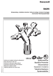
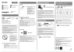
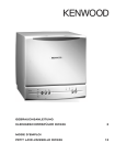
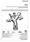
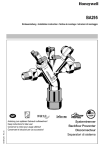
VE300
Einbauanleitung Installation instructions
Istruzioni di montaggio
Instrukcja montażu
EBA-VE300 Rev.A
Anleitung zum späteren Gebrauch aufbewahren!
Keep instructions for later use!
Conserver la notice pour usage ultérieur!
Conservare le istruzioni per uso successivo!
Zachowa instrukcj do pózniejszego wykorzystania!
Návod uschovejte pro pozdější použití!
Notice de montage
Návod na montáž
Heizungswasser-Behandlungseinheit
Heater water treatment unit
L'appareil de traitement
de l'eau de chauffage
L'unitŕ di trattamento dell'acqua
di riscaldamento
Zespół do zmiękczania wody grzewczej
Jednotka na úpravu topné vody
D
1.
5.
Sicherheitshinweise
1. Beachten Sie die Einbauanleitung.
2. Benutzen Sie das Gerät
• bestimmungsgemäß
• in einwandfreiem Zustand
• sicherheits- und gefahrenbewusst.
3. Beachten Sie, dass das Gerät ausschließlich für den in
dieser Einbauanleitung genannten Verwendungsbereich
bestimmt ist. Eine andere oder darüber hinausgehende
Benutzung gilt als nicht bestimmungsgemäß.
4. Beachten Sie, dass alle Montage-, Inbetriebnahme,
Wartungs- und Justagearbeiten nur durch autorisierte
Fachkräfte ausgeführt werden dürfen.
5. Lassen Sie Störungen, welche die Sicherheit beeinträchtigen können, sofort beseitigen.
2.
6.
7.
Wasser
max. 6,0 bar
• Installation im Zulauf der Heizungsanlage, Heizungswasser-Behandlungseinheit (VE300) an der Wand befestigen
• Einbau in waagrechte Rohrleitung
• Der Einbau darf nicht in Räumen oder Schächten erfolgen,
in denen giftige Gase oder Dämpfe auftreten und die überflutet werden können (Hochwasser)
• Der Einbauort muss frostsicher und gut belüftet sein
• Der Einbauort muss gut zugänglich sein
- Vereinfacht Wartung und Reinigung
• Gemäß DIN EN 1717 in Durchflussrichtung zunächst
Nachfüllkombination (NK300), dann unmittelbar danach
Heizungswasser-Behandlungseinheit (VE300) installieren
• Bei der Montage sind die nationalen Installationsvorschriften zu beachten.
• Bei einer Installation ohne Nachfüllkombination (NK300)
vor der Heizungswasser-Behandlungseinheit (VE300)
eine Absperreinrichtung vorsehen
Geeignet für Heizungsanlagen mit folgenden Werkstoffen: Stahl, Kupfer, Kupferlegierungen und Kunststoffe (bei Enthärtung) und Aluminium,
Aluminiumlegierungen, Stahl, Kupfer, Kupferlegierungen und Kunststoffe (bei Vollentsalzung).
7.2. Montageanleitung
Aufbereitetes Wasser hat veränderte korrosionschemische Parameter. Eine Konditionierung mittels Inhibitoren ist separat vorzusehen.
4.
1.
2.
Technische Daten
Einbaulage
waagrecht
Betriebstemperatur
max. 30 °C
kvs-Wert
0,45 m3/h
Anschlussgröße
1/2" Außengewinde
Honeywell GmbH
Montage
7.1. Einbauhinweise
Verwendung
Vordruck
Standardausführung mit Gewindeanschluss R1/2"
Beim Einbau sind die Einbauanleitung, geltende Vorschriften
sowie die allgemeinen Richtlinien zu beachten.
Funktionsbeschreibung
Medium
Varianten
VE300-1/2A =
Die unmittelbar nach der Nachfüllkombination (NK300) installierte Heizungswasser-Behandlungseinheit (VE300) arbeitet
bei Enthärtung nach dem Ionentauscherprinzip und ersetzt
die im Wasser befindlichen Erdalkalien wie Calcium und
Magnesium durch Natriumionen.
Abhängig von der regionalen Wasserhärte wird über die
Einstellung der Heizungswasser-Behandlungseinheit das
Wasser wahlweise teilenthärtet (<8°dH) oder vollenthärtet
(<0,11°dH).
Bei Vollentsalzung werden alle Salze aus dem Wasser
herausgenommen!
Bei Vollentsalzung muss die Verschneidung auf 0 gestellt
werden!
3.
Lieferumfang
Die Heizungswasser-Behandlungseinheit (VE300) besteht
aus:
• Verschneideeinrichtung, bestehend aus Wasserzähler,
ausgangsseitiger Absperrmöglichkeit und Entnahmeventil
• Edelstahl-Haltebügel mit Befestigungsset
• Verschraubungen mit Aussengewinde
• Gesamthärtemessbesteck zur Bestimmung der Wasserhärte
3.
4.
2
Bei der Montage gelten die nationalen Installationsvorschriften.
Absperrvorrichtung vorsehen um Patronentausch
sicher zu stellen.
Rohrleitung gut durchspülen
Heizungswasser-Behandlungseinheit (VE300) einbauen
und mittels der Wandhalterung befestigen
• Einbau in waagrechte Rohrleitung
• Durchflussrichtung beachten (Pfeilrichtung)
• spannungs- und biegemomentfrei einbauen
Einbauhöhe min. 55cm vom Boden aus vorsehen, um
Patronentausch sicher zu gewährleisten
Patrone (siehe Zubehör) in Heizungswasser-Behandlungseinheit (VE300) schrauben und handfest anziehen
MU1H-1547GE23 R0712
D
8.
Inbetriebnahme
9.1.1. Austausch Enthärter-oder VollentsalzungsPatrone
Wenn das Füllvolumen der Heizungsanlage die angegebene Kapazität übersteigt, muss ein Patronenwechsel vorgenommen werden.
Ermittlung der maximalen Kapazität der Patrone siehe
EBA-P300L beziehungsweise EBA-P300LES
Bei Enthärtung:
Die maximale Kapazität wird anhand der Gesamtwasserhärte und der Verschneideeinstellung ermittelt.
Die Kapazität wird auf der mitgelieferten Tabelle notiert,
ebenso wie die jeweils nachgefüllten Wassermengen.
Wenn das Füllvolumen den notierten Wasserzählerendstand übersteigt, muss ein Patronenwechsel vorgenommen werden.
Ein Wechsel der Enthärterpatrone wird aus Gründen
der technischen Sicherheit spätestens 12 Monaten
nach der ersten Verwendung empfohlen.
Bei Vollentsalzung:
Die maximale Kapazität wird anhand der Leitfähigkeit
und der Verschneideeinstellung ermittelt.
Die Kapazität wird auf der mitgelieferten Tabelle notiert,
ebenso wie die jeweils nachgefüllten Wassermengen.
Wenn das Füllvolumen den notierten Wasserzählerendstand übersteigt, muss ein Patronenwechsel vorgenommen werden.
Ein Wechsel der Vollentsalzugnspatrone wird aus
Gründen der technischen Sicherheit spätestens
12 Monate nach der ersten Verwendung empfohlen.
1. Absperrkugelhähne ein- und ausgangsseitig an der
Enthärtungseinheit schließen
2. Ausgangsseite durch Öffnen des Probenahmeventils
(Entlüftungsventil an Heizungswasser-Behandlungseinheit druckentlasten
3. Patrone aus Heizungswasser-Behandlungseinheit
herausdrehen
4. Neue Patrone handfest eindrehen
5. Absperrkugelhähne ein- und ausgangsseitig öffnen
8.1. Enthärtung einstellen
1. Messung der Wasserhärte
Mit Hilfe des mitgelieferten Gesamthärtemessbestecks
sollte vor der Installation die Wasserhärte gemessen
werden.
Beachten Sie die Hinweise in der Anleitung des
Gesamthärtemessbestecks
2. Heizungswasser-Behandlungseinheit (VE300) mit
blauem Verstellgriff einstellen
• Die geeignete Verschneideeinstellung (Markierung 0-3
auf Gehäuse der Enthärtungseinheit, ggf. Dämmschale
entfernen ) ist abhängig von der regionalen Wasserhärte und der gewünschten Resthärte. Der Wert kann
der auf der Patrone angebrachten Tabelle entnommen
werden.
8.2. Vollentsalzung einstellen
1. Messung der Leitfähigkeit
• Mit Hilfe eines Leitfähigkeitsmessgerät sollte vor der
Installation die Leitfähigkeit gemessen werden.
2. Heizungswasser-Behandlungseinheit (VE300) mit
blauem Verstellgriff einstellen
• Bei Vollentsalzung muss die Verschneidung auf
0 gestellt werden!
8.3. Anlage füllen
1. Absperrkugelhähne ein- und ausgangsseitig an der
Enthärtungseinheit langsam öffnen
2. Nach Befüllen der Anlage Absperrkugelhähne schließen
3. Notieren Sie die auf dem Aufkleber der Enthärter-oder
Vollentsalzungs-Patrone erforderlichen Parameter
9.
Instandhaltung
Wartungs-, Instandhaltungs- und Reparaturarbeiten
dürfen nur von autorisiertem Fachkräfte durchgeführt
werden.
9.1. Wartung
Wir empfehlen einen Wartungsvertrag mit einem Installationsunternehmen abzuschließen
Entsprechend DIN EN 1717 muss eine regelmäßige Wartung
durchgeführt werden.
Intervall: 1-3 Jahre (abhängig von den örtlichen Bedingungen)
Durchführung durch ein Installationsunternehmen.
10. Entsorgung
• Gehäuse aus entzinkungsbeständigem Messing
• Mechanische Komponenten der HeizungswasserBehandlungseinheit aus hochwertigem Kunststoff
• Dichtungen aus EPDM
Die örtlichen Vorschriften zur ordnungsgemäßen Abfallverwertung bzw. Beseitigung beachten!
11. Störungen / Fehlersuche
Störung
Ursache
Behebung
Kein oder zu wenig Durchfluss
Absperrkugelhähne vor oder nach
Nachfüllkombination nicht ganz geöffnet
Absperrkugelhähne ganz öffnen
MU1H-1547GE23 R0712
3
Honeywell GmbH
D
12. Serviceteile
13. Zubehör
2
2192900
VST06-B
D06F
AD300
P300-S/L / P300-LES
D V
1
G
N
Nr. Bezeichnung
Nennweite Artikelnummer
1
Wasserzähler
WZ300
2
Entlüftungsventil
2421100
NK300
BA295
2192900 Absperrkugelhahn
Anschlussgröße 1/2"
VST06-B Anschluss-Set
Mit Löttülle
P300-S Enthärter-Patrone
0,75l Enthärter-Patrone mit Ionentauscher-Harz
P300-L Enthärter-Patrone
3,5l Enthärter-Patrone mit Ionentauscher-Harz
P300-LES Vollentsalzungs-Patrone
3,5l Vollentsalzungs-Patrone mit AustauscherHarz
AD300 Adapter
Zum Anschluss der Enthärtungseinheit an 3/4"
Aussengewinde
D06F
Druckminderer
Schallschutz-Druckminderer mit Einstellskala
Vordruck max. 16 bar mit Klarsichtsiebtasse, 25 bar
mit Messingsiebtasse, Hinterdruck 1,5 - 6 bar
A = Klarsichtsiebtasse bis 40°C / 16 bar
B = Messingsiebtasse bis 70°C / 25 bar
BA295
NK300
Honeywell GmbH
4
Systemtrenner
Zur Absicherung von Trinkwasseranlagen gegen
Rückdrücken, Rückfließen und Rücksaugen.
Abgesichert werden Flüssigkeiten bis einschließlich Flüssigkeitskategorie 4 nach DIN EN 1717.
Nachfüllkombination
Flüssigkeitskategorie 4, mit Manometer, Absperrkugelhahn und Isolierschale
MU1H-1547GE23 R0712
GB
1.
5.
Safety Guidelines
1. Follow the installation instructions.
2. Use the appliance
• according to its intended use
• in good condition
• with due regard to safety and risk of danger.
3. Note that the appliance is exclusively for use in the applications detailed in these installation instructions. Any
other use will not be considered to comply with requirements and would invalidate the warranty.
4. Please take note that any assembly, commissioning,
servicing and adjustment work may only be carried out by
authorized persons.
5. Immediately rectify any malfunctions which may influence
safety.
2.
6.
7.
Inlet pressure
max. 6,0 bar
• Installation in the inlet to the heating system, fasten the
heater water treatment unit (VE300) to the wall
• Installation into horizontal pipeline
• The installation may not take place in areas or ducts where
poisonous gases or vapours may be present or where flooding can occur
• The installation environment should be protected against
frost and ventilated well
• The installation location has to be easily accessible
- Simplified maintenance and cleaning
• Acc. to DIN EN 1717 in direction of flow, first install the
refilling combination (NK300) and directly after it, the
heater water treatment unit (VE300)
• The national installation regulations must be observed
during the assembly.
• When installing a refilling combination (NK300) above the
heater water treatment unit (VE300), provide a shut-off
device
Suitable for heating systems with the following materials: Steel, copper, copper alloys and plastics (for
softening) and aluminium, aluminium alloys, steel,
copper, copper alloys and plastic (for complete demineralisation).
7.2. Assembly instructions
Treated water has modified corrosive chemical parameters. Conditioning by means of inhibitors is to be
provided for separately.
4.
1.
2.
Technical data
Installation position
horizontal
Operating temperature
max. 30 °C
kvs-value
0.45 m3/h
Connection size
1/2" External thread
3.
4.
Honeywell GmbH
Assembly
7.1. Installations Guidelines
Application
Water
Standard version with threaded connection
R1/2"
It is necessary during installation to follow the installation
instructions, to comply with local requirements and to follow
the codes of good practice.
Description of function
Medium
Options
VE300-1/2A =
The heater water treatment unit (VE300) installed directly
below the refilling combination (NK300) uses the ionic
exchange principle to soften water, replacing alkaline earths
such as calcium and magnesium with sodium ions.
Depending on the regional water hardness, the heater water
treatment unit is set to partially soften (<8°dH) or completely
soften (<0.11°dH) the water.
Complete demineralisation will completely remove the
mineral deposits in the water!
For complete demineralisation, the dilution must be set to 0!
3.
Scope of delivery
The heater water treatment unit (VE300) consists of:
• Blending unit, consisting of water flow meter, outlet-sided
blocking capability and bleeder valve
• Stainless steel mounting bracket with connection set
• Threaded male connections
• Total hardness test-kit to determine water hardness
5
The national installation regulations apply during the
assembly.
Provide shut-off device to safeguard cartridge
exchange
Thoroughly flush pipework
Install heater water treatment unit (VE300) and secure in
place with the wall bracket
• Install in horizontal pipeline
• Note flow direction (indicated by arrow)
• Install without tension or bending stresses
Set installation height min. 55cm from the ground to
ensure reliable cartridge exchange.
Screw the cartridge (see accessories) into the heater
water treatment unit (VE300) and tighten by hand
MU1H-1547GE23 R0712
GB
8.
Start-up
9.1.1. Changing the softening or complete demineralisation cartridge
When the filling level of the heating system exceeds the
specified capacity, a cartridge exchange has to be
performed.
To determine the maximum capacity of the cartridge,
refer to EBA-P300L or EBA-P300LES
For softening:
The maximum capacity is determined according to the
total water hardness and the dilution setting.
The capacity is noted on a table included in the scope of
delivery, as well as the respectively added amounts of
water. If the filling level exceeds the noted water flow
meter end value, a cartridge exchange has to be
performed.
An exchange of the softening cartridge is recommended
at least 12 months after its first usage due to technical
safety purposes.
For complete demineralisation
The maximum capacity is determined according to the
conductivity and the dilution setting.
The capacity is noted on a table included in the scope of
delivery, as well as the respectively added amounts of
water. If the filling level exceeds the noted water flow
meter end value, a cartridge exchange has to be
performed.
An exchange of the demineralisation cartridge is recommended at least 12 months after its first usage due to
technical safety purposes.
1. Close the ball valve on the inlet and outlet side of the blending unit
2. Decompress the outlet side by opening the sampling
valve (air bleed valve of the heater water treatment unit)
3. Unscrew the cartridge from the heater water treatment
unit
4. Screw the new cartridge in manually
5. Open ball valves on the inlet and outlet side
8.1. Adjust softening
1. Measuring the water hardness with support from the total
hardness test-kit, included in the scope of delivery, the
water hardness should be measured before the installation.
Observe the information in the instruction manual of the
total hardness test-kit
2. Adjust heater water treatment unit (VE300) with blue
adjuster knob
• The suitable dilution setting (marker 0-3 on the casing
of the dilution unit, remove insulation lining if necessary) is dependant on the regional water hardness and
the desired residual hardness. The value can be
extracted from the table attached to the cartridge.
8.2. Set to complete demineralisation
1. Measure the conductivity
• Before installation, an electrical conductivity meter
should be used to measure the conductivity.
2. Adjust heater water treatment unit (VE300) with blue
adjuster knob
• For complete demineralisation, the dilution must be set
to 0!
8.3. Filling up the system
1. Slowly open the ball valve on the inlet and outlet side of
the blending unit
2. After filling up the system, close the ball valves
3. Note the required parameters listed on the label of the
softening or complete demineralisation cartridge
9.
Maintenance
Maintenance, service and repair work may be carried
out only by authorised technicians.
9.1. Maintenance
We recommend a planned maintenance contract with
an installation company
In accordance with DIN EN 1717 a regular maintenance must
be taken.
Frequency: every 1-3 years (depending on local operating conditions)
To be carried out by an installation company
10. Disposal
• Dezincification-resistant brass housing
• Mechanical components of the heater water treatment unit
made of high-quality plastic
• EPDM sealing washers
Observe the local requirements regarding correct waste
recycling/disposal!
11. Troubleshooting
Problem
Cause
No or too small water flow rate
Ball valves up- or downstream of refilling combi- Open ball valves entirely
nation are not fully open
MU1H-1547GE23 R0712
Remedy
6
Honeywell GmbH
GB
12. Spare Parts
13. Accessories
2
2192900
VST06-B
D06F
AD300
P300-S/L / P300-LES
D V
1
G
N
No. Description
Dimension Part No.
1
Water flow meter
WZ300
2
Air bleed valve
2421100
BA295
NK300
2192900 Shutoff valve
Connection size 1/2"
VST06-B Connection set
Solder connections
P300-S Softening cartridge
0.75l softening cartridge with ionic exchange resin
P300-L Softening cartridge
3.5l softening cartridge with ionic exchange resin
P300-LES Complete demineralisation cartridge
3.5l complete demineralisation cartridge with
exchange resin
AD300 Adapter
To fit the softening unit to a 3/4“ male connection.
D06F
Pressure reducing valve
Noise protected pressure reducing valve with
setting scale. Maximum inlet pressure 16 bar, with
brass filter bowl 25 bar, outlet pressure range 1.5 6.0 bar
A = With clear filter bowl up to 40 °C / 16 bar
B = With brass filter bowl up to 70 °C / 25 bar
BA295 Backflow Preventer
To protect drinking water systems against back
pressure, backflow and withdrawal. Protection
against fluids up to and including fluid category 4
acc. to DIN EN 1717.
NK300 Refilling combination
Liquid catagory 4, with pressure gauge, shutoff
valve and isolating shell
Honeywell GmbH
7
MU1H-1547GE23 R0712
F
1.
Consignes de sécurité
5.
1. Suivre les indications de la notice de montage.
2. En ce qui concerne l'utilisation de l'appareil
• Utiliser cet appareil conformément aux données du
constructeur
• Maintenir l'appareil en parfait état
• Respectez les consignes de sécurité
3. Il faut noter que cet équipement ne peut être mis en
oeuvre que pour les conditions d'utilisation mentionnées
dans cette notice. Toute autre utilisation, ou le non
respect des conditions normales d'utilisation, serait considérée comme non conforme.
4. Observer que tous les travaux de montage, de mise en
service, d'entretien et de réglage ne pourront être effectués que par des spécialistes agréés.
5. Prendre des mesures immédiates en cas d'anomalies
mettant en cause la sécurité.
2.
6.
7.
7.1. Dispositions à prendre
• Montage sur la conduite d'amenée de l'installation de
chauffage, fixer l'appareil de traitement de l'eau de chauffage (VE300) au mur
• Montage sur une conduite horizontale
• Le montage ne doit pas être effectué dans des locaux ou
des conduits dans lesquels des gaz ou des vapeurs
toxiques apparaissent et qui peuvent être ventilés (montée
de l'eau)
• Le lieu de montage doit être protégé contre le gel et bien
aéré
• Le lieu de montage doit être accessible facilement
- Pour simplifier l'entretien et le nettoyage
• Installer la combinaison de remplissage (NK300) en amont
dans le sens de circulation de l'eau, puis directement en
aval l'appareil de traitement de l'eau de chauffage (VE300)
conformément à DIN EN 1717
• Lors du montage, les consignes d'installation nationales
en vigueur doivent être respectées.
• Lors du montage sans combinaison de remplissage
(NK300), prévoir un dispositif d'arrêt avant l'appareil de
traitement de l'eau de chauffage (VE300)
Mise en oeuvre
Eau
6,0 bar max.
Destiné aux installations de chauffage contenant les
éléments suivants : acier, cuivre, alliages cuivreux et
matières plastique (pour l'adoucissement) et aluminium, alliages d'aluminium, acier, cuivre, alliages cuivreux et matières plastique (pour le dessalement
complet).
7.2. Instructions de montage
Les consignes d'installation nationales en vigueur
prévalent lors du montage.
Prévoir un dispositif d'arrêt afin de permettre le remplacement des cartouches.
1. Bien rincer la conduite
2. Monter l'appareil de traitement de l'eau de chauffage
(VE300) et l'immobiliser au moyen de la fixation murale
• Montage sur une conduite horizontale
• Contrôlez la direction de l'écoulement (direction de la
flèche)
• Vérifier l'absence de contraintes anormales en traction
et en flexion
L'eau traitée possède des paramètres de corrosion
chimiques différents. Un conditionnement au moyen
d'inhibiteurs de corrosion doit être prévu séparément.
4.
Caractéristiques
Montage
Température de fonctionnement
Valeur du kvs
Dimensions de raccordement
Honeywell GmbH
Montage
Pour le montage, respecter la notice d’installation, les consignes en vigueur et les directives générales.
Description fonctionelle
Fluide
Pression amont
Variantes
VE300-1/2 A = Modèle standard avec raccord fileté R1/2"
L'appareil de traitement de l'eau de chauffage (VE300)
installé directement en aval de la combinaison de remplissage (NK300) fonctionne selon le principe d'échange d'ions
lors de l'adoucissement, et remplace les alcalinoterreux qui
se trouvent dans l'eau, comme le calcium et le magnésium,
par des ions sodium.
Le réglage de l'appareil de traitement de l'eau de chauffage
permet de sélectionner un adoucissement partiel de l'eau
(<8°dH) ou un adoucissement complet (<0,11°dH) selon la
dureté de l'eau de la région.
Lors du dessalement complet, l'eau est débarrassée de tous
ses sels.
Lors du dessalement complet, le mitigeur doit être réglé sur 0.
3.
Contenu de la livraison
L'appareil de traitement de l'eau de chauffage (VE300)
comprend :
• un mitigeur constitué d'un compteur de l'eau, d'une possibilité d'arrêt du côté sortie et d'une valve de purge
• un étrier de blocage en acier inoxydable avec un kit de
fixation
• des raccords vissés à filetage extérieur
• un dispositif de mesure de la dureté totale pour déterminer
la dureté de l'eau
horizontal
30 °C max.
0,45 m3/h
1/2'' filetage extérieur
8
MU1H-1547GE23 R0712
F
9.1.1. Remplacement des cartouches d'adoucissement
ou de dessalement complet
Si le volume de remplissage de l'installation de chauffage dépasse la capacité affichée, la cartouche doit être
remplacée.
Pour déterminer la capacité maximale de la cartouche,
voir EBA-P300L et EBA-P300LES
Lors de l'adoucissement :
La capacité maximale est déterminée en fonction de la
dureté de l'eau totale et du réglage du mitigeur.
La capacité est inscrite dans un tableau compris dans la
livraison, en fonction de la quantité d'eau remplie. Si le
volume de remplissage dépasse la valeur finale indiquée par le compteur d'eau, la cartouche doit être remplacée.
La cartouche d'adoucissement doit être remplacée au
plus tard 12 mois après la première utilisation pour des
raisons de sécurité technique.
Lors du dessalement complet :
La capacité maximale est déterminée en fonction de la
conductivité et du réglage du mitigeur.
La capacité est inscrite dans un tableau compris dans la
livraison, en fonction de la quantité d'eau remplie. Si le
volume de remplissage dépasse la valeur finale indiquée par le compteur d'eau, la cartouche doit être remplacée.
La cartouche de dessalement complet doit être remplacée au plus tard 12 mois après la première utilisation
pour des raisons de sécurité technique.
1. Fermer lentement les robinets d'arrêt à boisseau
sphérique des côtés entrée et sortie situés sur l'adoucisseur
2. Réduire la pression du côté sortie en ouvrant la vanne de
prise d'échantillon (vanne d'échappement de l'appareil de
traitement de l'eau de chauffage)
3. Dévisser la cartouche de l'appareil de traitement de l'eau
de chauffage
4. Visser une nouvelle cartouche à la main
5. Ouvrir les robinets d'arrêt à boisseau sphérique des côtés
entrée et sortie
3. Prévoir une hauteur de montage à 55cm min. du sol afin
de permettre le remplacement des cartouches
4. Visser les cartouches (voir accessoires) dans l'appareil
de traitement de l'eau de chauffage (VE300) et les serrer
à la main
8.
Mise en service
8.1. Réglage de l'adoucissement
1. Mesure de la dureté de l'eau La dureté de l'eau doit être
mesurée avant le montage au moyen du dispositif de
mesure de la dureté totale compris dans la livraison.
Respecter les consignes de la notice du dispositif de
mesure de la dureté totale
2. Régler l'appareil de traitement de l'eau de chauffage
(VE300) au moyen de la poignée de réglage bleue
• Le réglage correct du mitigeur (marques 0-3 sur le
boîtier de l'adoucisseur, retirer l'enveloppe isolante si
nécessaire) dépend de la dureté de l'eau de la région et
de la dureté souhaitée. Se reporter aux tableaux dont
dispose la cartouche pour connaître la valeur.
8.2. Réglage du dessalement complet
1. Mesure de la conductivité
• La conductivité doit être mesurée avant le montage au
moyen d'un appareil de mesure de la conductivité.
2. Régler l'appareil de traitement de l'eau de chauffage
(VE300) au moyen de la poignée de réglage bleue
• Lors du dessalement complet, le mitigeur doit être réglé
sur 0.
8.3. Remplissage de l'installation
1. Ouvrir lentement les robinets d'arrêt à boisseau
sphérique des côtés entrée et sortie situés sur l'adoucissseur
2. Fermer les robinets d'arrêt à boisseau sphérique une fois
l'installation remplie
3. Noter sur l'autocollant de la cartouche d'adoucissement
ou de dessalement complet les paramètres obligatoires
9.
Maintenance
Les travaux d'entretien, de maintenance et de réparation ne doivent être effectué que par un personnel
professionnel autorisé.
10. Matériel en fin de vie
9.1. Maintenance
• Corps en laiton résistant à la dézincification
• Éléments mécaniques de l'appareil de traitement de l'eau
de chauffage en matières plastique de haute qualité
• Joints en EPDM
Se conformer à la réglementation pour l'élimination des
équipements industriels en fin de vie vers les filières de
traitement autorisées!
Nous recommandons de souscrire à un contrat d'entretien avec un installateur
On devra réaliser une maintenance régulière conformément
à la norme DIN EN 1717.
Périodicité:De 1 à 3 ans en fonction des conditions
d'utilisation
Opération effectuée par un professionnel
11. Défaut / recherche de panne
Panne
Peu ou trop peu d'écoulement
MU1H-1547GE23 R0712
Cause
Remède
Robinet de fermeture pas complètement ouvert Ouvrir complètement le robinet de fermeavant ou après la combinaison de remplissage ture
9
Honeywell GmbH
F
12. Apercu pièces
13. Accessoires
2
2192900
VST06-B
D06F
AD300
P300-S/L / P300-LES
1
D V
G
N
N° Désignation
1
2
Compteur d'eau
Vanne d'échappement
Honeywell GmbH
Diamètre
nominal
Numéro
d'article
WZ300
2421100
BA295
NK300
2192900 Robinet d'arrêt à boisseau sphérique
Taille du raccord 1/2"
VST06-B Set de raccord
Avec douille à souder
P300-S Cartouche d'adoucissement
Cartouche d'adoucissement de 0,75l avec résine
échangeuse d'ions
P300-L Cartouche d'adoucissement
Cartouche d'adoucissement de 3,5l avec résine
échangeuse d'ions
P300-LES Cartouche de dessalement complet
Cartouche de dessalement complet de 3,5l avec
résine échangeuse d'ions
AD300 Adaptateur
Destiné au raccord de l'adoucisseur à un filetage
extérieur de 3/4''
D06F
Régulateur de pression
Régulateur de pression antibruit avec échelle de
réglage. Pression d’alimentation maxi. 16 bar avec
pot de décantation transparent, 25 bar avec pot de
décantation en laiton,
A = pot de décantation transparent jusqu’à 40°C /
16 bar
B = pot de décantation en laiton jusqu’à
70°C / 25 bar
BA295 Séparateur de système
Pour sécuriser les installations d'eau portable
contre la contre-pression, le contre-écoulement et
la contre-aspiration. Les liquides y compris la catégorie 4 selon DIN En 1717 sont sécurisés.
NK300 Combinaison de remplissage
Catégorie de fluide 4, avec manomètre, robinet
d'arrêt à boisseau sphérique et coque isolante
10
MU1H-1547GE23 R0712
I
1.
Avvertenze di sicurezza
5.
Fornitura
1. Rispettare le istruzioni di montaggio.
2. Utilizzare l'apparecchio
- secondo la destinazione d'uso
- solo se integro
- in modo sicuro e consapevoli dei pericoli connessi
3. Si prega di considerare che l'apparecchio è realizzato
esclusivamente per il settore d'impiego riportato nelle
presenti istruzioni d'uso. Un uso differente o diverso da
quello previsto è da considerarsi improprio.
4. Osservare che tutti i lavori di montaggio, di messa in
funzione, di manutenzione e di regolazione devono
essere eseguiti soltanto da tecnici specializzati e autorizzati.
5. I guasti che potrebbero compromettere la sicurezza
devono essere risolti immediatamente.
L'unità di trattamento dell'acqua di riscaldamento (VE300) è
costituita da:
• miscelatore, costituito da contatore acqua, innesto per
dispositivo di chiusura in uscita e valvola di prelievo
• Staffa in acciaio inox con kit di fissaggio
• Collegamenti a vite con filettatura esterna
• kit di misura della durezza totale per la determinazione
della durezza dell'acqua
2.
• Installazione nella tubazione di mandata dell'impianto di
riscaldamento. Fissare l'unità di trattamento dell'acqua di
riscaldamento (VE300) alla parete
• Installazione su tubazione orizzontale
• È vietata l'installazione in locali o pozzetti in cui si possano
generare gas o vapori nocivi e soggetti a allagamento
(acqua di piena)
• Il luogo di installazione deve essere protetto dal gelo e
deve essere ben ventilato
• Il luogo di installazione deve essere di facile accesso
- Rende più semplice la manutenzione e la pulizia
• Secondo DIN EN 1717, installare nella direzione del flusso
prima il gruppo di riempimento (NK300) e subito a valle
l'unità di trattamento dell'acqua di riscaldamento (VE300)
• Durante il montaggio devono essere rispettate le norme di
installazione nazionali.
• In caso di installazione senza gruppo di riempimento
(NK300), prevedere un dispositivo di bloccaggio a monte
dell'unità di trattamento dell'acqua di riscaldamento
(VE300)
6.
7.
7.1. Istruzioni di installazione
Descrizione del funzionamento
Uso
Mezzo
acqua
Pressione a monte max. 6,0 bar
Adatto per impianti di riscaldamento con i seguenti
materiali: acciaio, rame, leghe di rame e materiali sintetici (addolcimento) e alluminio, leghe di alluminio,
acciaio, rame, leghe di rame e materiali sintetici (demineralizzazione totale).
7.2. Istruzioni di montaggio
L’acqua trattata ha parametri chimici corrosivi modificati. Un condizionamento con inibitori deve essere
previsto separatamente.
4.
1.
2.
Dati tecnici
Posizione di installazione
orizzontale
Temperatura di esercizio
max. 30 °C
kvsValore
0,45 m3/h
Dimensioni attacchi
1/2" filettatura esterna
Honeywell GmbH
Versione standard con attacco filettato R1/2"
Montaggio
Al montaggio è necessario osservare il manuale di
montaggio, le norme vigenti nonché le direttive generali.
L'unità di trattamento dell'acqua di riscaldamento (VE300)
installata immediatamente a valle del gruppo di riempimento
(NK300) realizza l'addolcimento in base al principio dello
scambio ionico, sostituendo gli elementi alcalino-terrosi come
calcio e magnesio presenti nell'acqua con ioni di sodio.
In funzione della durezza dell'acqua locale, l'acqua può
essere addolcita parzialmente (<8°dH) o completamente
(<0,11°dH) impostando in modo corrispondente l'unità di trattamento.
Con la demineralizzazione totale, dall'acqua vengono eliminati tutti i sali!
Per la demineralizzazione totale il miscelatore deve essere
impostato su 0.
3.
Varianti
VE300-1/2A =
3.
4.
11
Durante il montaggio rispettare le norme di installazione
nazionali.
Prevedere un dispositivo di bloccaggio per garantire la
sostituzione delle cartucce.
Sciacquare bene la tubazione.
Installare l'unità di trattamento dell'acqua di riscaldamento (VE300) e fissarla con il supporto a parete
• Installazione su tubazione orizzontale
• Osservare la direzione di flusso (direzione della freccia)
• senza tensione e momento flettente
Prevedere un'altezza di installazione di almeno 55 cm dal
pavimento per garantire una sostituzione sicura delle
cartucce
Avvitare la cartuccia (vedere accessori) nell'unità di
trattamento dell'acqua di riscaldamento (VE300) e
serrarla a mano
MU1H-1547GE23 R0712
I
8.
Messa in servizio
8.1. Regolazione dell'addolcimento
1. Misurazione della durezza dell'acqua Prima dell'installazione eseguire una misurazione con il kit di misura della
durezza totale in dotazione.
Osservare le avvertenze nelle istruzioni del kit di misura
della durezza totale
2. Impostare l'unità di trattamento dell'acqua di riscaldamento (VE300) con la manopola di regolazione blu
• La corretta regolazione del miscelatore (tacca 0-3 sul
corpo del miscelatore, se necessario rimuovere il
guscio isolante) dipende dalla durezza dell'acqua
locale e dalla durezza residua desiderata. Il valore si
trova nella tabella riportata sulla cartuccia.
8.2. Regolazione della demineralizzazione totale
1. Misurazione della conducibilità
• Prima dell'installazione, misurare la conducibilità con
l'ausilio di un apposito dispositivo di misurazione.
2. Impostare l'unità di trattamento dell'acqua di riscaldamento (VE300) con la manopola di regolazione blu
• Per la demineralizzazione totale il miscelatore deve
essere impostato su 0.
8.3. Riempimento dell'impianto
1. Aprire lentamente i rubinetti di chiusura in ingresso e in
uscita sull'unità di addolcimento
2. Terminato il riempimento dell'impianto chiudere i rubinetti
di chiusura
3. Prendere nota dei parametri richiesti sull'etichetta della
cartuccia di addolcimento o di demineralizzazione totale
9.
Manutenzione
La manutenzione ordinaria e straordinaria e le riparazioni devono essere eseguite esclusivamente da personale qualificato e autorizzato.
9.1. Manutenzione
Consigliamo di stipulare un contratto di manutenzione
con un'azienda di installazione
In conformità alla norma DIN EN 1717 bisogna eseguire una
manutenzione periodica.
Frequenza: ogni 1-3 anni (in base alle condizioni
presenti) Esecuzione ad opera di un'azienda di installazione
11. Guasti / Ricerca guasti
Guasto
Flusso assente o troppo basso
MU1H-1547GE23 R0712
9.1.1. Sostituzione di una cartuccia di addolcimento o di
demineralizzazione totale
1. Se il volume di riempimento dell'impianto di
riscaldamento supera la capacità indicata sostituire
la cartuccia.
Per la determinazione della capacità massima della
cartuccia, vedere le istruzioni per P300L o per P300LES
Per addolcimento:
La capacità massima viene determinata in base alla
durezza totale dell'acqua e all'impostazione del miscelatore.
La capacità è riportata nelle tabelle in dotazione
assieme alle rispettive quantità di acqua riempita. Se il
volume di riempimento supera il livello finale riportato
per il contatore dell'acqua, sostituire la cartuccia.
Per ragioni di sicurezza tecnica si raccomanda di sostituire la cartuccia di addolcimento al più tardi 12 mesi
dopo il primo utilizzo.
Per demineralizzazione totale:
La capacità massima viene determinata in base alla
conducibilità e all'impostazione del miscelatore.
La capacità è riportata nelle tabelle in dotazione
assieme alle rispettive quantità di acqua riempita. Se il
volume di riempimento supera il livello finale riportato
per il contatore dell'acqua, sostituire la cartuccia.
Per ragioni di sicurezza tecnica si raccomanda di sostituire la cartuccia di demineralizzazione totale al più tardi
12 mesi dopo il primo utilizzo.
1. Chiudere i rubinetti di chiusura in ingresso e in uscita
sull'unità di addolcimento
2. Scaricare la pressione sul lato di uscita aprendo la valvola
di prelievo (valvola di sfiato dell'unità di trattamento
dell'acqua di riscaldamento)
3. Svitare e rimuovere la cartuccia dall'unità di trattamento
dell'acqua di riscaldamento
4. Serrare a mano la nuova cartuccia
5. Aprire i rubinetti di chiusura in ingresso e in uscita
10. Smaltimento
• Corpo in ottone resistente alla dezincatura
• Componenti meccanici dell'unità di trattamento dell'acqua
di riscaldamento in materiale sintetico di alta qualità
• Guarnizioni in EPDM
Rispettare le norme locali relative al riciclaggio o allo
smaltimento a regola d'arte di rifiuti!
Causa
Risoluzione
Rubinetti di chiusura a monte e a valle del gruppo Aprire completamente i rubinetti
di riempimento non aperti completamente
12
Honeywell GmbH
I
12. Pezzi di ricambio
13. Accessori
2
2192900
VST06-B
D06F
AD300
P300-S/L / P300-LES
1
D V
G
N
N. Denominazione
1
2
contatore dell'acqua
valvola di sfiato
Larghezza- N. art.
nominale
WZ300
2421100
BA295
NK300
2192900 Rubinetto di chiusura
Dimensione dell'attacco 1/2"
VST06-B Kit di allacciamento
Con becco saldato
P300-S Cartuccia di addolcimento
Cartuccia di addolcimento da 0,75 litri con resina
per scambio ionico
P300-L Cartuccia di addolcimento
Cartuccia di addolcimento da 3,5 litri con resina
per scambio ionico
P300-LES Cartuccia di demineralizzazione totale
Cartuccia di demineralizzazione totale da 3,5 litri
con resina per scambio
AD300
Adattatore
Per il collegamento dell'unità di addolcimento alla
filettatura esterna da 3/4"
D06F
BA295
NK300
Honeywell GmbH
13
Riduttore di pressione
Riduttore di pressione ad isolamento acustico con
scala di regolazione. Pressione a monte max. 16
bar con tazza di filtro trasparente, 25 bar con tazza
di filtro di ottone, pressione a valle 1,5 - 6 bar
A = tazza di filtro trasparente fino a 40°C / 16 bar
B = tazza di filtro di ottone fino a 70°C / 25 bar
Separatore di sistema
Per la sicurezza degli impianti di acqua potabile
contro inversione di pressione, riflusso e sifonaggio. La sicurezza è garantita per i liquidi fino
alla categoria di liquidi 4 compresa (secondo DIN
EN 1717).
Gruppo di riempimento
Categoria di liquidi 4, con manometro, rubinetto di
chiusura e guscio di isolamento
MU1H-1547GE23 R0712
PL
1.
5.
Wskazówki bezpieczeDstwa
Zakres dostawy
1. Przestrzegać instrukcji montażu.
2. Proszę użytkować urządzenie
• zgodnie z jego przeznaczeniem
• w nienagannym stanie
• ze świadomością bezpieczeństwa i zagrożeń
3. Proszę uwzględnić, że urządzenie przeznaczony jest
wyłącznie dla zakresu zastosowania określonego w
niniejszej instrukcji montażu. Każde inne lub
wykraczające poza to użytkowanie uznawane jest jako
niezgodne z przeznaczeniem.
4. Proszę uwzględnić, że wszystkie prace montażowe mogą
być wykonywane tylko przez autoryzowany personel
fachowy.
5. Wszystkie usterki, które mogą naruszyć bezpiec zeństwo
należy natychmiast usunąć.
Zespół do zmiękczania wody grzewczej (VE300) składa się z
następujących komponentów:
• urządzenie mieszające, składające się z wodomierza,
możliwości odcięcia po stronie wyjściowej i zaworu
czerpalnego
• jarzma mocującego ze stali nierdzewnej z zestawem
montażowym
• dwuzłączek z gwintem zewnętrznym
• zestaw pomiarowy twardości ogólnej do określania
twardości wody
2.
Podczas montażu przestrzegaę instrukcji montażu,
obowiązujacych przepisów oraz ogólnych zasad
6.
VE300-1/2A =
7.
Opis funkcji
Zespół do zmiękczania wody grzewczej, zainstalowany
bezpośrednio za zespołem napełniającym, pracuje na
zasadzie wymiany jonów i zamienia zawarte w wodzie jony
metali alkalicznych (wapnia i magnezu) na jony sodu.
W zależności od twardości wody w regionie i ustawienia
zespołu zmiękczającego, woda może zostaę zmiękczona
częściowo (<8űdH) lub całkowicie (<0,11űdH).
W przypadku całkowitego odsalania wody usunięte z niej
zostają wszystkie sole!
Przy odsalaniu całkowitym rowek musi byę ustawiony w
pozycji 0!
3.
7.2. Instrukcja montażu
Dane techniczne
poziomo
max. 30 °C
0,45 m3/h
1/2" gwint zewnętrzny
1.
2.
3.
4.
Honeywell GmbH
Montaż
• Montaż w dopływie instalacji grzewczej, zespół do
zmiękczania wody (VE300) mocowany jest do ściany
• Montaż w poziomym przewodzie rurowym
• Nie wolno montowaę w pomieszczeniach lub szybach, w
których występują trujące gazy lub pary i które mogłyby
ulec zalaniu (powódź)
• Miejsce montażu musi byę wolne od mrozu i dobrze
przewietrzane
• Miejsce montażu musi byę łatwo dostępne
- UŠatwia konserwacjÍ i czyszczenie
• Zgodnie z DIN EN 1717 w kierunku przepływu należy
zainstalowaę najpierw zespół napełniający (NK300), a
zaraz po nim zespół do zmiękczania wody (VE300)
• Przy montażu należy przestrzegaę lokalnych krajowych
przepisów montażowych.
• Jeśli nie jest montowany zespół napełniający (NK300), to
przed zespołem do zmiękczania wody (VE300) należy
zainstalowaę zawór odcinający
Zastosowanie
Pozycja montażowa
Temperatura robocza
Wartośę kvs
Rozmiar przyłącza
Wersja standardowa z podłączeniem na
gwint R1/2"
7.1. Montaż
Czynnik
Woda
Ciśnienie wejściowe
maks. 6,0 bar
Do instalacji grzewczych zawierających następujące
materiały: stal, miedź, stopy miedzi i tworzywa sztuczne
(w przypadku zmiękczania) oraz aluminium, stopy
aluminium, stal, miedź, stopy miedzi i tworzywa
sztuczne (w przypadku całkowitego odsalania wody).
Uzdatniona woda ma zmienione parametry korozyjne.
Należy oddzielnie przewidzieę zabezpieczenie za
pomocą inhibitorów korozji.
4.
Warianty
14
Przy montażu należy przestrzegaę lokalnych krajowych
przepisów montażowych.
Należy przewidzieę zawór odcinający, aby umożliwię
wymianę wkładów.
Dokładnie przepłukaę przewód przyłączeniowy
Zamontowaę zespół do zmiękczania wody (VE300) i
przymocowaę przy użyciu uchwytu ściennego
• Montaż w poziomym przewodzie rurowym
• Przepływ w kierunku wskazanym przez strzałkę
• w stanie wolnym od naprężeń i momentów zginających
Wysokośę montażu powinna wynosię min. 55 cm od
posadzki, aby umożliwię wymianę wkładu
Przykręcię i mocno dociągnąę wkład (patrz akcesoria) w
zespole do zmiękczania wody (VE300)
MU1H-1547GE23 R0609
PL
8.
Uruchomienie
9.1.1. Wymiana wkładu do zmiękczania lub odsalania
wody
Wkład należy wymienię w przypadku, gdy zostanie
przekroczona podana pojemnośę instalacji grzewczej.
Maksymalna pojemnośę wkładu Đ patrz EBA-P300L lub
EBA-P300LES
W przypadku zmiękczania:
Maksymalna pojemnośę określana jest na podstawie
całkowitej twardości wody i ustawienia rowka.
Objętośę jest notowana na dołączonej tabeli, tak jak i
właśnie uzupełniona ilośę wody. Jeśli objętośę
napełniania instalacji grzewczej przekroczy
zanotowaną wartośę odczytaną na wodomierzu, to
wkład musi zostaę wymieniony.
Ze względu na techniczne bezpieczeństwo wkład
zmiękczający zaleca się wymienię najpóźniej 12
miesięcy po pierwszym użyciu.
W przypadku całkowitego odsalania:
Maksymalna pojemnośę określana jest na podstawie
przewodności i ustawienia rowka.
Objętośę jest notowana na dołączonej tabeli, tak jak i
właśnie uzupełniona ilośę wody. Jeśli objętośę
napełniania instalacji grzewczej przekroczy
zanotowaną wartośę odczytaną na wodomierzu, to
wkład musi zostaę wymieniony.
Ze względów bezpieczeństwa technicznego wkład do
całkowitego odsalania wody powinien zostaę
wymieniony najpóźniej po upływie 12 miesięcy od
pierwszego użycia.
1. Zamknąę kulowe zawory odcinające po stronie
wejściowej i wyjściowej zespołu zmiękczającego
2. Zredukowaę całkowicie ciśnienie po stronie wyjściowej,
otwierając zawór próbkowy (zawór odpowietrzający na
zespole do zmiękczania wody)
3. Odkręcię wkład z zespołu do zmiękczania wody
4. Przykręcię mocno rękoma nowy wkład
5. Otworzyę kulowe zawory odcinające po stronie
wejściowej i wyjściowej
8.1. Regulacja zmikczania wody
1. Pomiar twardości wody
Przed montażem należy określię stopień twardości wody
przy użyciu dołączonego zestawu do pomiaru twardości
całkowitej.
Należy przestrzegaę wskazówek w instrukcji zestawu
pomiarowego do twardości ogólnej
2. Ustawię zespół do zmiękczania wody (VE300) niebieską
dźwignią nastawczą
• Ustawienie rowka (kreski 0-3 na obudowie zespołu
zmiękczającego, w razie potrzeby usunąę ocieplenie)
zależy od twardości wody w regionie i żądanej
twardości resztkowej. Wartośę podana została w tabeli
na wkładzie.
8.2. Regulacja całkowitego odsalania
1. Pomiar przewodności
• Przed montażem należy zmierzyę przewodnośę za
pomocą odpowiedniego przyrządu.
2. Ustawię zespół do zmiękczania wody (VE300) niebieską
dźwignią nastawczą
• Przy odsalaniu całkowitym rowek musi byę ustawiony
w pozycji 0!
8.3. Napełnianie instalacji
1. Powoli otworzyę kulowe zawory odcinające po stronie
wejściowej i wyjściowej zespołu zmiękczającego
2. Zamknąę kulowe zawory odcinające po napełnieniu
instalacji
3. Zanotowaę parametry podane na naklejce, na wkładzie
do zmiękczania lub odsalania wody
9.
Utrzymywanie w dobrym stanie
Prace konserwacyjne, pielgnacyjne oraz naprawcze
mo|e przeprowadza wyBcznie autoryzowany personel.
9.1. Konserwacja
Zalecamy zawarcie umowy konserwacyjnej z
odpowiednią firmą instalacyjną
Zgodnie z DIN EN 1717 konieczna jest regularna
konserwacja.
Okres: raz w roku Przeprowadzenie przez firmę
instalacyjną
10. Usuwanie
• Korpus wykonany z mosiądzu odpornego na
odcynkowanie
• Zespoły mechaniczne zespołu do zmiękczania wody,
wykonane z wysokiej jakości tworzywa sztucznego
• Uszczelki z EPDM
Należy stosowaę się do miejscowych przepisów
dotyczących prawidłowego wykorzystania odpadów
wzgl. ich usuwania!
11. Zakłócenia / poszukiwanie usterek
Zakłócenie
Przyczyna
Usuwanie
Brak przepływu lub przepływ za małyKulowe zawory odcinające przed lub za
zespołem napełniającym nie są otwarte
całkowicie
MU1H-1547GE23 R0609
15
Otworzyę odcinający zawór kulowy
Honeywell GmbH
PL
12. Części zamienne
13. Wyposażenie dodatkowe
2
2192900
VST06-B
D06F
AD300
P300-S/L / P300-LES
1
D V
G
N
Nr Oznaczenie
rednicaznam Numer artyku
ionowa
1
Wodomierz
WZ300
2
Zawór odpowietrzający
2421100
NK300
BA295
2192900 Kulowy zawór odcinający
Średnica przyłącza 1/2"
VST06-B Zestaw przyłączeniowy
z tuleją lutowaną
P300-S Wkład zmiękczający
Wkład zmiękczający 0,75 l z żywicowym
wymiennikiem jonowym
P300-L Wkład zmiękczający
Wkład zmiękczający 3,5 l z żywicowym
wymiennikiem jonowym
P300-LES Wkład do całkowitego odsalania wody
Wkład do całkowitego odsalania wody 3,5 l z
wymiennikiem żywicowym
AD300 Adapter
Do podłączenia urządzenia zmiękczającego do
gwintu zewnętrznego 3/4"
D06F
Reduktor ciśnienia
tor ciśnienia z izolacją akustyczną i skalą
nastawcząCiśnienie dolotowe maks. 16 bar z
przezroczystą obudową filtra, 25 bar z mosiężną
obudową filtra, ciśnienie wylotowe 1,5 ń 6 barA =
przezroczysta obudowa filtra do 40°C / 16 barB =
mosiężna obudowa filtra do 70°C / 25 bar
BA295
NK300
Honeywell GmbH
16
Zespół odcinający
Zabezpieczający systemy wody pitnej przed
ciśnieniami wstecznymi, przepływem i zasysaniem
zwrotnym. Zabezpieczone są ciecze o kategorii 4 i
niższej godnie z DIN EN 1717.
Zespół napełniający
Kategoria cieczy 4, z manometrem, kulowym
zaworem odcinającym i osłoną izolacyjną
MU1H-1547GE23 R0609
CZ
1.
Bezpečnostní pokyny
5.
1. Respektujte návod k montáži.
2. Používejte přístroj
• přiměřeně jeho účelu
• v bezvadném stavu
• bezpečně a s vědomím možných nebezpečí.
3. Dbejte na to, že přístroj je určen výhradně pro oblast
použití uvedenou v tomto návodu k montáži. Jiné, nebo
nad tento rámec jdoucí použití platí jako nepřiměřené.
4. Dbejte na to, že všechny montážní, údržbářské a nasta
vovací činnosti i uvádění do provozu smí provádět pouze
autorizovaný odborný personál.
5. Poruchy, které mohou ovlivnit bezpečnost, nechejte
neprodleně odstranit!
2.
6.
7.
• Instalaci provete do pívodní vtve topného zaízení,
jednotku na úpravu topné vody (VE300) pipevnte na stnu
• Montáž do vodorovného úseku potrubí
• Montáž nesmí probíhat v prostorech nebo šachtách, v
nichž se vyskytují plyny nebo páry, nebo které mohou být
zatopeny (velká voda).
• Místo montáže musí být mrazuvzdorné a dobře větrané.
• Místo montáže musí být dobře přístupné.
- Zjednodušená údržba a ištní
• Podle SN EN 1717 instalujte ve smru prtoku nejprve doplo
vací kombinaci (NK300), pak bezprostedn za ní jednotku
na úpravu topné vody (VE300)
• U montáže je nutné dbát příslušných národních předpisů.
• Pi instalaci bez doplovací kombinace (NK300) umístte ped
jednotkou na úpravu topné vody (VE300) vhodné
uzavírací zaízení
Použití
Voda
Vhodné pro topná zaízení z tchto materiál: ocel, m,
slitiny mdi a plasty (pi zmkování); hliník, slitiny hliníku,
ocel, m, slitiny mdi a plasty (pi úplné demineralizaci).
7.2. Návod k montáži
Zpracovaná voda má změněné korozně chemické
parametry. Příprava prostřednictvím inhibitorů musí být
provedena zvlášť.
Při montáži platí příslušné národní předpisy.
Technické údaje
Poloha při montáži
1.
2.
vodorovně
Provozní teplota
max. 30 °C
kvs-hodnota
0,45 m3/h
Přípojná velikost
1/2" Vnější závit(y)
3.
4.
Honeywell GmbH
Montáž
7.1. Pokyny pro instalaci
Vstupní tlakmax. 6,0 bar
4.
Standardní provedení včetně závitové
přípojky R1/2"
Při montáži je nutné dodržovat návod k montáži, platné
předpisy i všeobecné pokyny.
Popis funkce
Médium
Varianty
VE300-1/2A =
Jednotka na úpravu topné vody (VE300) instalovaná
bezprostedn za doplovací kombinací (NK300) pracuje pi
zmkování na principu výmny iont a nahrazuje alkalické prvky
rozpuštné ve vod (vápník, hoík) za ionty sodíku.
V závislosti na místní tvrdosti vody lze pomocí nastavení
jednotky na úpravu topné vody zmkovat ásten (na hodnoty
<8°dH), nebo úpln (<0,11°dH).
Pi úplné demineralizaci (deionizaci) jsou z vody odstranny
všechny minerálie!
Pi úplné demineralizaci musí být záez nastavený na nulu!
3.
Objem dodávky
Jednotka na úpravu topné vody (VE300) má tyto souásti:
• Mísicím zařízením, které se skládá z vodoměru, možnosti
uzavírání na straně výstupu a ventilu odběru.
• Uchycovací třmen z ušlechtilé oceli včetně upevňovací
sady
• Šroubové spoje s vnějším závitem
• Měřicí pozice pro určení tvrdosti vody
17
Nainstalujte uzavírací zařízení z důvodu zabezpečení
výměny pantron.
Dobře propláchnout potrubí
Instalujte jednotku na úpravu topné vody (VE300) a
pipevnte ji pomocí nástnného držáku
• Montáž do vodorovného úseku potrubí
• Dejte pozor na správný smr prtoku (viz šipka)
• Namontovat bez mechanického namáhání pnutím a
ohybem
K zajištní možnosti výmny patron dodržte montážní výšku
min. 55 cm nad podlahou
Zašroubujte patronu (viz Píslušenství) do jednotky na
úpravu topné vody (VE300) a rukou ji utáhnte
MU1H-1547GE23 R0712
CZ
8.
Uvedení do provozu
9.1.1. Výmna zmkovací nebo demineralizaní patrony
Pekroí-li plnicí objem topného zaízení uvedenou kapa
citu, je teba vymnit patronu.
Urení maximální kapacity patrony viz montážní návod
P300L resp. montážní návod P300LES
Pi zmkování:
Maximální kapacita se urí na základ celkové tvrdosti
vody a nastavení záezu.
Kapacita i již doplněné množství vody jsou poznačeny
do dodané tabulky. Když objem plnění překročí
zapsaný konečný stav vodoměru, musí být provedena
výměna patrony.
Výměna patrony změkčovače je z bezpečnostních
důvodů doporučena nejpozději 12 měsíců po prvním
použití.
Pi úplné demineralizaci:
Maximální kapacita se urí na základ elektrické vodivosti
vody a nastavení záezu.
Kapacita i již doplněné množství vody jsou poznačeny
do dodané tabulky. Když objem plnění překročí
zapsaný konečný stav vodoměru, musí být provedena
výměna patrony.
Výmna patrony pro úplnou demineralizaci se z dvod
technické bezpenosti doporuuje nejpozdji 12msíc po
prvním použití.
1. Pomalu zavete uzavírací kulové kohouty na vstupní a
výstupní stran zmkovací jednotky
2. Otevením ventilu k odbru vzork (odvzdušovacího ventilu
na jednotce na úpravu topné vody) odtlakujte výstupní
stranu
3. Vyšroubujte patronu z jednotky na úpravu topné vody
4. Zašroubujte novou patronu, pevn ji rukou utáhnte
5. Otevete uzavírací kulové kohouty na vstupní a výstupní
stran
8.1. Nastavte změkčení
1. Mení tvrdosti vody:
Pomocí dodané soupravy k mení celkové tvrdosti zmte
ped instalací tvrdost vody.
Dodržujte pokyny v návodu měřicí pozice pro určení
tvrdosti vody.
2. Nastavení jednotky na úpravu topné vody (VE300)
modrou regulaní rukojetí
• Vhodné nastavení záezu (na znaku 0 až 3 na skíni
zmkovací jednotky; pípadn odstrate izolaci) závisí na
tvrdosti místní vody a požadované zbytkové tvrdosti.
Píslušnou hodnotu zjistíte z tabulky uvedené na patron.
8.2. Nastavení úplné demineralizace
1. Mení vodivosti
• Ped instalací zmte konduktometrem (miem vodivosti)
vodivost.
2. Nastavte jednotku na úpravu topné vody (VE300) modrou
regulaní rukojetí
• Pi úplné demineralizaci musí být záez nastavený na
nulu!
8.3. Zařízení naplňte
1. Pomalu otevete uzavírací kulové kohouty na vstupní a
výstupní stran zmkovací jednotky
2. Po naplnní zaízení kohouty opt uzavete
3. Poznamenejte si požadované parametry uvedené na
nálepce zmkovací nebo demineralizaní patrony
9.
Údržba
Údržbové, servisní a opravářské práce smí provádět
pouze povolaný odborník.
9.1. Údržba
Doporučujeme Vám uzavřít smlouvu o údržbě
s instalatérskou firmou
Podle DIN EN 1717 musí být údržba prováděna pravidelně.
Interval: 1-3 roky (v závislosti na místních podmínkách).
Provést prostřednictvím instalatérské firmy.
10. Likvidace
• Kryt z odolné mosazi bez zinku.
• Mechanické souásti jednotky na úpravu topné vody z
jakostního plastu
• Těsnění z EPDM
Respektujte místní předpisy pro správnou recyklaci
popř. likvidaci odpadu!
11. Poruchy / hledání závady
Porucha
Příčina
Odstranění
Žádný nebo příliš malý průtok
Uzavírací kulové kohouty před nebo za doplň
kovou kombinací nejsou zcela otevřeny
Uzavírací kulové kohouty zcela otevřete
MU1H-1547GE23 R0712
18
Honeywell GmbH
CZ
12. Náhradní díly
13. Příslušenství
2
2192900
VST06-B
D06F
AD300
P300-S/L / P300-LES
D V
1
G
N
č. Popis
číslo výrobku
1
Vodoměr
WZ300
2
Odvzdušňovací ventil
2421100
BA295
NK300
2192900 Uzavírací kulový kohout
Připojovací velikost 1/2"
VST06-B Připojovací sada
S přípojkou pro připájení
P300-S Zmkovací patrona
Zmkovací patrona 0,75 l s pryskyicí pro iontovou
výmnu
P300-L Zmkovací patrona
Zmkovací patrona 3,5 l s pryskyicí pro iontovou
výmnu
P300-LES Demineralizaní patrona
Demineralizaní patrona 3,5 l s pryskyicí pro
iontovou výmnu
AD300 Adapter
Pro připojení změkčovací jednotky vody k
vnějšímu závitu 3/4"
D06F
Redukční ventil
Ochrana proti hluku-redukční ventil se stupnicí
nastavenívstupní tlak max. 16 bar s průhlednou
filtrační miskou , 25 bar s filtrační miskou z mosazi,
výstupní tlak 1,5 - 6 barA = průhledná filtrační
miska až 40°C / 16 barB = filtrační miska z mosazi
až 70°C / 25 bar
BA295
NK300
Honeywell GmbH
19
Systémová separace
Kvůli zabezpečení systémů s pitnou vodou proti
zpětnému tlaku, toku a sání. Zabezpečeny jsou
tekutiny až do kategorie 4 podle DIN EN 1717.
Doplňovací kombinace
Kategorie kapaliny 4, s manometrem, uzavíracím
kulovým kohoutem a izolační miskou
MU1H-1547GE23 R0712
Automation and Control Solutions
Honeywell GmbH
Hardhofweg
74821 MOSBACH
GERMANY
Phone: (49) 6261 810
Fax: (49) 6261 81309
www.honeywell.com
Manufactured for and on behalf of the
Environmental and Combustion Controls Division of
Honeywell Technologies Sàrl, Z.A. La Pièce 16,
1180 Rolle, Switzerland by its Authorised Representative Honeywell GmbH
MU1H-1547GE23 R0712
Subject to change
© 2012 Honeywell GmbH
8.1.
2.
8.2
8.3.
2.
2.
2.
1.
1.
2.
2.
1.
1.
3.
9.2
9.1.
5.
5.
1.
2.
5.
5.
1.
1.
2.
1.
3.
3.
4.
MU1H-1547GE23 R0712
3.
4.
Honeywell GmbH
D
1.
2.
3.
4.
5.
6.
7.
8.
9.
10.
11.
12.
13.
Sicherheitshinweise ............................ 2
Funktionsbeschreibung ...................... 2
Verwendung ....................................... 2
Technische Daten ............................... 2
Lieferumfang ....................................... 2
Varianten ............................................ 2
Montage .............................................. 2
Inbetriebnahme ................................... 3
Instandhaltung .................................... 3
Entsorgung ......................................... 3
Störungen / Fehlersuche .................... 3
Serviceteile ......................................... 4
Zubehör .............................................. 4
1.
2.
3.
4.
5.
6.
7.
8.
9.
10.
11.
12.
13.
Safety Guidelines ............................... 5
Description of function ........................ 5
Application .......................................... 5
Technical data .................................... 5
Scope of delivery ................................ 5
Options ............................................... 5
Assembly ............................................ 5
Start-up ............................................... 6
Maintenance ....................................... 6
Disposal .............................................. 6
Troubleshooting .................................. 6
Spare Parts ......................................... 7
Accessories ........................................ 7
1.
2.
3.
4.
5.
6.
7.
8.
9.
10.
11.
12.
13.
Consignes de sécurité ........................ 8
Description fonctionelle ...................... 8
Mise en oeuvre ................................... 8
Caractéristiques .................................. 8
Contenu de la livraison ....................... 8
Variantes ............................................ 8
Montage .............................................. 8
Mise en service ................................... 9
Maintenance ....................................... 9
Matériel en fin de vie .......................... 9
Défaut / recherche de panne .............. 9
Apercu pièces ................................... 10
Accessoires ...................................... 10
I
1.
2.
3.
4.
5.
6.
7.
8.
9.
10.
11.
12.
13.
Avvertenze di sicurezza .................... 11
Descrizione del funzionamento ........ 11
Uso ................................................... 11
Dati tecnici ........................................ 11
Fornitura ........................................... 11
Varianti ............................................. 11
Montaggio ......................................... 11
Messa in servizio .............................. 12
Manutenzione ................................... 12
Smaltimento ...................................... 12
Guasti / Ricerca guasti ..................... 12
Pezzi di ricambio .............................. 13
Accessori .......................................... 13
1
2
3
4
5
6
7
8
9
10
11
12
13
Wskazówki bezpieczeDstwa ............ 14
Opis funkcji ....................................... 14
Zastosowanie ................................... 14
Dane techniczne ............................... 14
Zakres dostawy ................................ 14
Warianty ........................................... 14
Montaż .............................................. 14
Uruchomienie ................................... 15
Utrzymywanie w dobrym stanie ........ 15
Usuwanie .......................................... 15
Zakłócenia / poszukiwanie usterek ... 15
Części zamienne .............................. 16
Wyposażenie dodatkowe .................. 16
1.
2.
3.
4.
5.
6.
7.
8.
9.
10.
11.
12.
13.
Bezpečnostní pokyny ....................... 17
Popis funkce ..................................... 17
Použití ............................................... 17
Technické údaje ............................... 17
Objem dodávky ................................. 17
Varianty ............................................ 17
Montáž .............................................. 17
Uvedení do provozu ......................... 18
/držba ................................................ 18
Likvidace ........................................... 18
Poruchy / hledání závady ................. 18
Náhradní díly .................................... 19
Příslušenství ..................................... 19
GB
PL
F
MU1H-1547GE23 R0712
CZ
Honeywell GmbH