1
Mod.
1092
DS1092-090
THERA 5 MINIDOME P/T/Z ANTIVANDALO
DA ESTERNO CON ZOOM 10X
THERA 5 P/T/Z VANDAL-PROOF
OUTDOOR MINIDOME WITH 10X ZOOM
Sch./Ref. 1092/602
MANUALE DI INSTALLAZIONE ED USO
INSTALLATION AND USER MANUAL
ITALIANO
INDICE
1
Informazioni generali ............................................................................................................................. 3
1.1
Descrizione del prodotto......................................................................................................... 3
1.2
Apertura della confezione....................................................................................................... 3
1.2.1
2
3
1.3
Organizzazione del documento.............................................................................................. 3
Importanti norme di sicurezza .............................................................................................................. 4
Procedure di installazione..................................................................................................................... 6
3.1
Configurazione di un sistema minimale per l’uso di THERA 5............................................... 6
3.2
Tipologie di installazione ........................................................................................................ 6
3.2.1
3.2.2
3.2.3
4
Contenuto della confezione ................................................................................................................... 3
Installazione a parete. ........................................................................................................................... 7
Requisiti dei cavi per il collegamento .................................................................................................. 13
Dimensioni dei cavi d’alimentazione.................................................................................................... 13
Modalità di funzionamento .................................................................................................................. 14
4.1
Funzionamento all’accensione ............................................................................................. 14
4.2
Modalità di utilizzo tramite tastiera di comando ................................................................... 14
4.2.1
4.2.2
4.3
4.4
Sintassi dei comandi eseguibili da tastiera sch.1092/620 ................................................................... 15
Tipi di comandi eseguibili da tastiera................................................................................................... 15
Selezione della dome ........................................................................................................... 16
Operazioni di manovra della dome....................................................................................... 16
4.4.1
4.4.2
4.4.3
4.4.4
4.4.5
4.5
Funzioni di brandeggio orizzontale (pan) e verticale (tilt) .................................................................... 16
Funzioni di modifica ingrandimento (zoom) ......................................................................................... 17
Funzioni di modifica fuoco (focus) ....................................................................................................... 17
Funzioni di modifica apertura otturatore (iris) ...................................................................................... 17
Impostazione e richiamo di posizioni preimpostate (preset) ................................................................ 18
Impostazione delle modalità di funzionamento tramite menu .............................................. 18
4.5.1
4.5.2
4.5.3
4.5.4
4.5.5
4.5.6
4.5.7
Menu relativo alle informazioni sul prodotto ........................................................................................ 19
Menu relativo alle visualizzazioni ........................................................................................................ 19
Impostazioni da menu relative alle programmazioni principali (Control Options) ................................ 20
Impostazioni da menu relative alle programmazioni principali (Diagnostic Options) ........................... 21
Impostazioni da menu relative alle programmazioni secondarie (Camera options)............................. 21
Descrizione del sistema dei menu....................................................................................................... 21
Descrizione delle voci di menu ............................................................................................................ 22
4.5.7.1
4.5.7.2
4.5.7.3
4.5.7.4
4.5.7.5
4.5.7.6
4.5.8
Impostazioni da menu relative alle programmazioni (function programming)...................................... 30
4.5.8.1
4.5.8.2
4.5.8.3
4.5.8.4
4.5.8.5
4.5.8.6
4.5.8.7
4.6
Preset - memorizzazione della posizione e dello zoom della dome ............................................................. 31
Program vectorscan – definizione percorso costituito da preset, pattern e vectorscan................................ 31
Pattern – definizione percorso programmabile ............................................................................................. 33
Sector setup – definizione settori .................................................................................................................. 34
Masking zone- zona di mascheramento ....................................................................................................... 36
Motion – azionamenti automatici................................................................................................................... 36
Alarm in programming – azioni collegate agli allarmi.................................................................................... 39
Impostazioni hardware (dip-switch)...................................................................................... 41
4.6.1
4.6.2
4.6.3
4.6.4
5
6
Cam title – assegnazione di un nome alla dome .......................................................................................... 22
White bal – bilanciamento del bianco ........................................................................................................... 22
Backlight – BLC – compensazione controluce.............................................................................................. 24
Focus– impostazioni dello zoom ................................................................................................................... 24
Exposure– esposizione ................................................................................................................................. 26
Special– regolazioni speciali ......................................................................................................................... 28
Impostazione della dome..................................................................................................................... 41
Impostazione dell’indirizzo................................................................................................................... 41
Impostazioni di baud rate .................................................................................................................... 43
Impostazioni di protocollo di comunicazione ....................................................................................... 43
Comandi speciali .................................................................................................................................. 44
Caratteristiche tecniche....................................................................................................................... 45
DS1092-090
2
1
INFORMAZIONI GENERALI
Caro cliente,
La ringraziamo dell’acquisto di questo prodotto.
Il presente documento descrive come installare ed utilizzare il modello di minidome THERA 5 URMET
Domus S.p.A. Sch.1092/602.
Prima di usare l’apparecchiatura, leggere il presente manuale che ne descrive l’uso corretto e sicuro.
Conservare questo manuale con attenzione ed in un luogo facilmente reperibile per poterlo consultare
prontamente quando necessario.
1.1
DESCRIZIONE DEL PRODOTTO
La minidome Sch.1092/602 offre elevate prestazioni in termini di qualità video e di manovrabilità, con la
possibilità di riprendere immagini a colori ad alta qualità durante il giorno ed in bianco e nero durante la
notte.
Le minidome va abbinata a una tastiera di controllo, es.Sch.1092/620, Sch.1092/690 o Sch.1092/691 o
Sch.1092/692, e tramite questa consente il controllo di brandeggio orizzontale e verticale (pan e tilt) e di
ingrandimento (zoom) a velocità variabile, per la sorveglianza di aree remote in sistemi TVCC professionali.
1.2
APERTURA DELLA CONFEZIONE
Verificare che l’imballo ed il contenuto non presentino danni visibili. Se alcune parti non sono presenti o
risultano danneggiate, contattare immediatamente il rivenditore. In questi casi non tentare di utilizzare il
dispositivo. Se il prodotto dovesse essere rimandato al fornitore, assicurarsi di spedirlo con il suo imballo
originale.
1.2.1
CONTENUTO DELLA CONFEZIONE
N°1 modulo camera.
N°1 staffa da parete.
N°1 guarnizione in gomma per staffa da parete.
N°1 confezione contenente n°1 cacciavite, n°3 viti con guarnizione per fissaggio minidome, n°1
guarnizione circolare per staffa da parete, n°1 anello di raccordo metallico.
N°1 alimentatore dedicato.
N°1 cavo di collegamento.
Manuale istruzioni.
NOTA BENE
La composizione degli accessori a corredo può essere variata senza alcun preavviso.
1.3
ORGANIZZAZIONE DEL DOCUMENTO
Questo documento è composto delle seguenti parti fondamentali.
Una serie di avvertenze ed importanti norme di sicurezza
Le procedure per l’installazione della minidome, degli accessori utili al loro funzionamento e le
norme per collegare il tutto in un unico sistema video integrato.
Le modalità di funzionamento in abbinamento ad una tastiera e la gestione avanzate delle opzioni.
Specifiche tecniche riassuntive.
Ognuno dei capitoli che seguono approfondisce uno di questi argomenti.
DS1092-090
3
2
IMPORTANTI NORME DI SICUREZZA
Sono qui riportate importanti norme da seguirsi scrupolosamente per operare la telecamere Sch.1092/602 e
relativi accessori in condizioni di completa sicurezza.
Nel seguito con il termine “sistema video” si intende una minidome Sch.1092/602 comprendente tutto quanto
possa servire per renderla operativa (ad esempio, alimentazione, cavi, supporti, tastiera di controllo, od altro
ancora).
Leggere le istruzioni
Prima di procedere alla messa in funzione del sistema video, leggere con attenzione tutte le norme di
sicurezza e le istruzioni operative.
Conservare le istruzioni
Conservare le norme di sicurezza e le istruzioni d'uso per future evenienze.
Rispettare le avvertenze
Prestare attenzione a tutte le avvertenze riportate sulla minidome ed all'interno del manuale di installazione
ed uso.
Seguire le istruzioni
Attenersi esclusivamente alle istruzioni riportate nel manuale di installazione ed uso.
Pulizia
Scollegare tutte le parti elettriche dalla rete di alimentazione elettrica prima di pulirle.
Attacchi
Non utilizzare attacchi diversi da quelli raccomandati dal manuale di installazione ed uso in quanto questo
potrebbe comportare dei rischi per il prodotto.
Accessori
Non posizionare la minidome su carrelli instabili, treppiedi, staffe o tavoli. La minidome potrebbe cadere,
ferendo gravemente adulti o bambini e danneggiando seriamente il prodotto stesso. Per l’installazione della
minidome e la messa in opera del sistema video attenersi alle istruzioni del manuale di installazione ed uso
e utilizzare solo gli accessori raccomandati e forniti come accessori alla minidome.
Aerazione
Non posizionare mai la minidome vicino o sopra radiatori o fonti di calore. Installare la minidome all'interno di
zone parzialmente chiuse (quali nicchie, librerie, scaffali) a condizione che sia garantita un'opportuna
aerazione e previo rispetto delle istruzioni riportate nel libretto di installazione ed uso.
Alimentazione elettrica
Prevedere un interruttore per le operazioni di manutenzione della minidome.
Collegare la minidome esclusivamente al tipo di alimentazione elettrica indicata sulla targhetta. In caso di
dubbio relativamente al tipo di alimentazione, consultare il proprio rivenditore.
Protezione dei cavi di alimentazione
Effettuare la posa dei cavi di alimentazione in modo che non possano essere calpestati o schiacciati da
oggetti posti su di essi, prestando particolare attenzione ai cavi in corrispondenza di spine, viti e all'uscita dal
prodotto.
Fulmini
Al fine di proteggere la minidome durante i temporali o quando viene lasciata incustodita e non in uso per
lunghi periodi, scollegare l'alimentazione e il cablaggio. Questo impedirà il danneggiamento del sistema
video in caso di caduta di fulmine e sovraccarico della linea elettrica.
Sovraccarichi
Non sovraccaricare l'alimentazione elettrica e le prolunghe poiché ciò comporta rischio di incendio e di
scosse elettriche.
Infiltrazioni di liquidi e oggetti
Non inserire oggetti di alcun tipo attraverso le aperture della minidome in quanto potrebbero toccare punti ad
alta tensione con il rischio che si generi un incendio o una scossa elettrica. Non versare liquidi di alcun tipo
sul dispositivo.
DS1092-090
4
Riparazioni
Non cercare di riparare da soli la minidome (ed anche alcuna parte del sistema video) in quanto l'apertura o
la rimozione di alcune parti potrebbe esporre l'utente ad alte tensioni o altri pericoli. Rivolgersi
esclusivamente a tecnici d'assistenza qualificati.
Danni che richiedono il ricorso al servizio d'assistenza
Nei seguenti casi, scollegare il sistema video dalla rete di alimentazione e rivolgersi per l'assistenza tecnica
esclusivamente a personale qualificato.
In caso di danneggiamento del cavo o della spina di alimentazione.
In caso di versamento di liquidi o di caduta di oggetti all'interno del dispositivo.
In caso di funzionamento anomalo del dispositivo nonostante il rispetto delle istruzioni d'uso
contenute nel manuale.
In tale situazione, si raccomanda di agire solo sui comandi descritti nel manuale d’uso poiché una
regolazione impropria di altri comandi potrebbe aggravare la situazione e spesso rende necessario
un maggior lavoro da parte del tecnico qualificato al fine di ripristinare le normali condizioni di
funzionamento del dispositivo.
In caso di caduta del dispositivo, di forti urti o in caso di danneggiamento dell’involucro della
minidome.
Qualora le prestazioni del dispositivo mostrino un sensibile cambiamento.
Sostituzione di parti
Nel caso in cui si renda necessaria la sostituzione di parti, assicurarsi che il tecnico dell'assistenza utilizzi
ricambi secondo quanto specificato dal costruttore o parti aventi le stesse caratteristiche dei pezzi originali.
Sostituzioni non
autorizzate possono dare luogo a incendi, scosse elettriche o altri pericoli.
Controllo di sicurezza
Una volta completato qualunque intervento d'assistenza o di riparazione sul sistema video, richiedere al
tecnico dell'assistenza di eseguire i controlli di sicurezza per accertare che il tutto sia in condizioni operative
adeguate.
Precauzioni
Al fine di proteggere la minidome, evitare di installarla o utilizzarla sotto la luce diretta del sole o
esponendola a pioggia o polvere.
Non toccare le lenti dello zoom con le dita. Se necessario, utilizzare un panno morbido inumidito con
alcool per eliminare eventuali tracce di polvere.
Quando la minidome non viene utilizzata, applicare l'apposito cappuccio al fine di proteggere le lenti
dello zoom.
Non puntare la minidome contro il sole.
Non puntare la minidome contro fonti di luce intensa. La luce intensa come quella di un proiettore
può causare velature o macchie. Sullo schermo potrebbe comparire una striscia verticale. Questo
non è tuttavia indice di malfunzionamento.
Installare la minidome lontano da interferenze video. Se il cablaggio dei cavi è realizzato vicino a un
apparecchio TV o simili, le immagini potrebbero presentare delle interferenze. In tal caso spostare i
cavi o reinstallare l'apparecchio.
Privacy e Copyright
La minidome 1092/602 è un dispositivo per sistemi TVCC. La registrazione delle immagini è
subordinata alle leggi vigenti nel paese di utilizzo. È inoltre vietata la registrazione di immagini
protette da Copyright.
Gli utenti del prodotto sono responsabili per il controllo ed il rispetto di tutte le norme e gli statuti
locali relativi al monitoraggio e alla registrazione di segnali video. Il produttore NON potrà essere
ritenuto responsabile per un utilizzo di questo prodotto che non sia in conformità con le norme in
vigore. Per maggiori informazioni consultare l’indirizzo web http://www.garanteprivacy.it
DS1092-090
5
3
PROCEDURE DI INSTALLAZIONE
Questa sezione fornisce istruzioni dettagliate per l’installazione delle minidome THERA 5 Urmet Domus. Le
istruzioni presuppongono da parte dell’installatore una buona conoscenza delle tecniche di installazione e
l’adozione di metodi d’installazione sicuri.
3.1
CONFIGURAZIONE DI UN SISTEMA MINIMALE PER L’USO DI THERA 5
La minidome THERA 5 contiene un ricevitore incorporato che decodifica i comandi provenienti dalla tastiera
di comando Sch.1092/620 (fare riferimento al capitolo 4.2); Il funzionamento richiede quindi almeno una
tastiera di comando. Questa, oltre alla configurazione dei parametri di funzionamento, gestisce le
funzionalità di brandeggio sull'asse orizzontale (360° continui) e sull'asse verticale (180°), di zoom
motorizzato, di richiamo e programmazione delle sequenze predefinite di THERA 5.
3.2
TIPOLOGIE DI INSTALLAZIONE
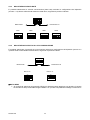
L'installazione di THERA 5 si articola in due possibili soluzioni.
a parete tramite staffa standard.
a parete tramite Kit con staffa e power box di collegamento IP66 Sch. 1092/628
Nota Bene
Indipendentemente dal tipo di installazione si consiglia di:
prevedere un interruttore per le operazioni di manutenzione della minidome.
assicurarsi che ai capi delle linee RS - 485 siano inserite le adeguate resistenze di terminazione
(120 Ω ¼ W) non fornite a corredo.
DS1092-090
6
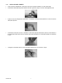
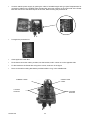
3.2.1
INSTALLAZIONE A PARETE.
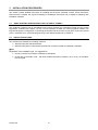
Prima d’iniziare l’installazione, assicurarsi che tutte le unità da collegare non siano alimentate.
Posizionare sulla staffa da parete l’anello di tenuta in gomma (oring), a corredo, nella apposita sede.
Inserire il cavo di collegamento della dome, in dotazione, all’interno della staffa fino a farlo fuoriuscire
dalla parte opposta.
Posizionare l’anello di raccordo, in dotazione, nella sede superiore della dome avendo cura di allineare i
tre fori presenti sulla dome ai tre fori presenti sull’anello aiutandosi con i riferimenti presenti su entrambe
le parti.
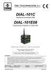
Collegare la morsettiera del cavo alla morsettiera della dome come indicato in figura.
DS1092-090
7
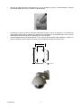
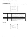
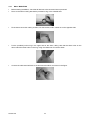
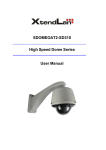
Bloccare la staffa alla dome utilizzando le viti con la rondella in gomma, a testa bombata a corredo
avvitandole saldamente nei fori presenti ai lati della staffa.
Posizionare la dome nel punto prescelto della parete avendo cura di far passare il cavo attraverso
l’asola situata nella staffa o praticare un ulteriore foro sulla parete in corrispondenza del cavo in uscita
dalla staffa di diametro sufficiente al passaggio del cavo intestato).
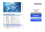
Fissarla saldamente alla parete utilizzando i 4 fori situati nella base della staffa mediante 4 viti M6 non
fornite in dotazione. Qui di seguito si riportano per comodità gli interassi di foratura in mm.
70
100
120
50
N°4 fori 8
DS1092-090
8
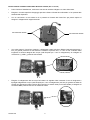
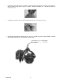
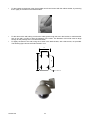
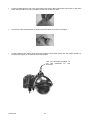
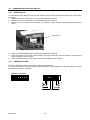
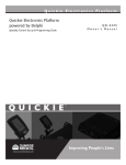
INSTALLAZIONE A PARETE CON POWER BOX SCH.1092/628 (Non a corredo)
Prima d’iniziare l’installazione, assicurarsi che tutte le unità da collegare non siano alimentate.
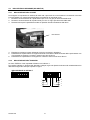
Eseguire i fori sulla superficie di appoggio prevista e fissare il Power Box utilizzando i 4 fori presenti alle
estremità del dispositivo.
Con un cacciavite e croce svitare le viti 4 presenti sul frontale del Power Box per poterlo aprire ed
eseguire i collegamenti di seguito descritti.
SVITARE PER APRIRE
SVITARE PER APRIRE
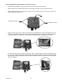
Una volta aperto il Power Box eseguire i collegamenti relativi alla linea RS485 inserendo attraverso il
foro più grande presente sul lato inferiore corredato di pressa cavo, un cavo a due conduttori della
lunghezza e sezione adeguati allo scopo (vedi Requisiti per i cavi di collegamento) da collegarsi ai
morsetti AA (+) e BB (-) presenti sulla scheda.
Eseguire il collegamento del cavo tipo RG relativo al segnale video inserendo il cavo di lunghezza e
tipologia adeguata allo scopo (vedi Requisiti per i cavi di collegamento) nel foro più grande corredato di
pressa cavo presente sul lato inferiore del Power Box (lo stesso usato per la linea RS485) e collegarlo al
connettore BNC presente nel cavo in dotazione al Box.
DS1092-090
9
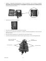
Eseguire il collegamento dell’alimentazione a 230 Vca inserendo il cavo di sezione e lunghezza
adeguata allo scopo (vedi Requisiti per i cavi di collegamento) nel foro più piccolo corredato di pressa
cavo presente nel lato inferiore del Box e collegandolo ai morsetti presenti sulla scheda dopo aver
rimosso il coperchio di protezione.
Riposizionare il coperchio di protezione.
Richiudere il Power Box nel modo inverso alla sua apertura.
Inserire il cavo di collegamento della dome, in dotazione, all’interno della staffa fino a farlo fuoriuscire
dalla parte opposta.
Bloccare la staffa al Power Box per mezzo delle 4 viti come indicato in figura.
Posizionare sulla staffa da parete l’anello di tenuta in gomma (oring), a corredo, nella apposita sede.
ANELLO DI TENUTA IN
GOMMA (ORING)
CAVO DI
COLLEGAMENTO
VITI DI BLOCCO
DS1092-090
VITI DI BLOCCO
10
Posizionare l’anello di raccordo, in dotazione, nella sede superiore della dome avendo cura di allineare i
due fori presenti sulla dome ai due fori presenti sull’anello aiutandosi con i riferimenti presenti su
entrambe le parti.
Collegare la morsettiera del cavo alla morsettiera della dome come indicato in figura.
Bloccare la staffa alla dome utilizzando le tre viti con la rondella in gomma, a testa bombata a corredo
avvitandole saldamente nei fori presenti ai lati della staffa.
UTILIZZARE LE VITI IN DOTAZIONE
PER BLOCCARE LA MINIDOME
ALLA STAFFA
DS1092-090
11
COLLEGAMENTI
Collegare il cavo in dotazione alla dome per mezzo delle morsettiere.
Collegare la seconda estremità del cavo al dispositivo video per mezzo del connettore BNC maschio.
Collegare i due fili della RS485 per mezzo di morsettiera o eseguendo una saldatura alla borchia della
tastiera (Sch.1092/620) rispettando le polarità : ARANCIO + (positivo) - GIALLO – (negativo).
Collegare i due fili di alimentazione per mezzo di morsettiera o eseguendo una saldatura ai due fili
dell’alimentatore fornito in dotazione (non è necessario rispettare le polarità).
Se la dome è l’ultimo dispositivo della linea RS485 (vedi COLLEGAMENTO LOGICO DELLA LINEA
RS485),collegare una resistenza da 120 Ohm ¼ w non in dotazione , sulla linea RS485.
Effettuare i collegamenti come indicato nel “DETTAGLIO DEI COLLEGAMENTI”
Collegare l’alimentatore alla presa di rete.
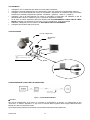
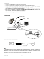
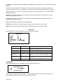
CONFIGURAZIONE
Cavo di collegamento
Alimentatore
Dome
COAX
SE IL DISPOSITIVO E’L’ULTIMO DELLA
LINEA
INSERIRE LA RESISTENZA DA 120 OHM
¼W
RS485
CONFIGURAZIONE LOGICA DELLA LINEA RS485.
Inserire resistenza
Figura 1: CONFIGURAZIONE MINIMA
Nota Bene
Nel caso di collegamento di più Dome, si consiglia la configurazione a cascata, con collegamenti di tipo
“entra-esci” su ciascun dispositivo. In ogni caso, la somma delle lunghezze delle singole tratte della linea
RS485 non deve mai superare 1200m.
Si ricorda di inserire sempre la resistenza di terminazione sull’ultima Dome della linea.
DS1092-090
12
3.2.2
REQUISITI DEI CAVI PER IL COLLEGAMENTO
Sono richiesti tre tipi di cavo:
1. Il cavo video, che trasporta il segnale video composito standard alla postazione di osservazione remota.
Normalmente si utilizza un cavo coassiale da 75 Ohm.
2. Il cavo di alimentazione per la minidome THERA 5 (alimentatore da 24Vca). Per determinare le
dimensioni del cavo, vedere la sezione “Dimensioni dei cavi d’alimentazione” di questo manuale.
3. Il cavo di comando RS485, che distribuisce i comandi dalla tastiera a THERA 5. È necessario un cavo
twistato a due conduttori, non schermato. Si consiglia un cavo di diametro 0,64 mm (22AWG).
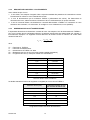
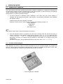
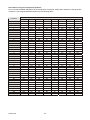
3.2.3
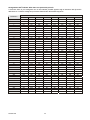
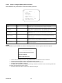
DIMENSIONI DEI CAVI D’ALIMENTAZIONE
È importante determinare la dimensione corretta del cavo che trasporta i 24V di alimentazione di THERA 5 .
Se il cavo è troppo piccolo sull’apparecchiatura, la caduta di tensione da esso determinata può causare un
funzionamento improprio. La seguente formula determina la tensione fornita a THERA 5 al variare delle
dimensioni del cavo.
VD VT
PD RW DW
VT 500
dove:
VD
VT
PD
RW
DW
= Tensione su THERA 5.
= Tensione del trasformatore.
= Assorbimento di THERA 5 in Watt.
= Resistenza del cavo in Ohm per metro (vedere tabella sottostante).
= Lunghezza del cavo (in metri) tra THERA 5 e l’alimentatore
Diametro del filo (mm)
Resistenza (Ohm/m)
2,60
3,35/1000
2,05
5,32/1000
1,63
8,46/1000
1,29
13,42/1000
1,02
21,36/1000
0,81
34,12/1000
0,64
54,14/1000
Diametro del filo e valori di resistenza
La tabella sottostante fornisce le lunghezze consigliate per il cavo di una THERA 5
Diametro del filo (mm)
Lunghezza massima dei cavi
per versione da esterno (m)
2,60
200
2,05
125
1,63
80
1,29
50
1,02
30
0,81
20
0,64
10
Lunghezza massima dei cavi di alimentazione
DS1092-090
13
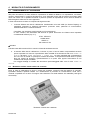
4
4.1
MODALITÀ DI FUNZIONAMENTO
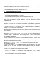
FUNZIONAMENTO ALL’ACCENSIONE
Alla prima accensione, la dome utilizza le impostazioni di default di fabbrica. Le impostazioni, se variate,
vengono memorizzate in maniera permanente e sono disponibili anche alle successive accensioni della
dome. Da notare che in qualsiasi momento si possono riportare le impostazioni al loro valore di default di
fabbrica agendo sulla voce di menu opportuna.
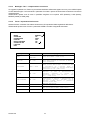
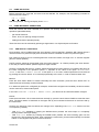
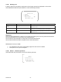
In fase di accensione la dome si comporta nel seguente modo.
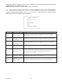
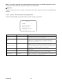
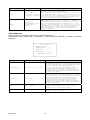
1. La dome effettua una fase di calibrazione visualizzando nel menù OSD (On Screen Display) un
messaggio riportante le seguenti informazioni: protocollo usato, parametri di comunicazione,
indirizzo della dome e versione software
Controllare che i dati siano quelli richiesti per il funzionamento.
In caso contrario, fare riferimento alla sezione di questo documento che illustra come impostare
correttamente la dome (cap. 4.7).
PTOL: PELCO-D
COMM: 9600
ADDR: 01
SW version X.XX
Nota Bene
Prendere nota della versione SW in caso di richiesta di assistenza tecnica
2. Al termine della fase di calibrazione, la dome si pone in fase di attesa comportandosi secondo
quanto impostato nel menu di impostazione delle modalità di funzionamento alla voce POWER UP
ACTION dal menu <DOME SETTINGS1 • POWER UP>. La dome mantiene tale comportamento
fino a che non si manda un qualunque comando da tastiera. Il comportamento della dome in questa
fase può essere ad esempio il posizionamento in un punto fisso oppure l’esecuzione di una
scansione nel campo di visibilità.
Per maggiori dettagli si rimanda alla descrizione particolareggiata della voce di menu POWER UP
ACTION.
4.2
Modalità di utilizzo tramite tastiera di comando
Dopo la fase di calibrazione la dome è pronta ad accettare comandi inviati da tastiera di comando.
E’possibile utilizzare qualsiasi tastiera con caratteristiche di protocollo di comunicazione, baud rate e
comandi compatibili con la dome. Di seguito viene descritto l’uso della tastiera Sch.1092/620 (vedi figura
successiva).
Tastiera di controllo Sch.1092/620
DS1092-090
14
4.2.1
SINTASSI DEI COMANDI ESEGUIBILI DA TASTIERA SCH.1092/620
È possibile dare comandi da tastiera usando tasti singoli, oppure una combinazione di tasti.
La sintassi di descrizione del comando formato da tasti è la seguente.
Sintassi di comandi formati da tasti
La sintassi usata in questo manuale per i comandi formati da tasti consiste in una serie di elementi che
possono essere parole oppure numeri a tre cifre decimali. Ogni comando è sempre delimitato da parentesi
ed ogni elemento è separato da virgole. Ogni parola o cifra decimale usata nella sintassi è l’identificativo di
un corrispondente tasto nella tastiera Sch.1092/620. Le parole possono essere racchiuse da parentesi
tonde, da parentesi quadre o da nessuna parentesi. I numeri a tre cifre decimali non sono mai racchiusi fra
parentesi.
In seguito viene mostrato in dettaglio come usare i comandi con alcuni esempi applicativi.
Uso di un tasto singolo
La pressione di un singolo tasto può provocare un’azione sulla dome. Ad esempio, il comando seguente
provoca un ingrandimento dell’inquadratura. La sottolineatura del testo in stampatello indica l’uso del tasto.
TELE
Uso combinato di tasti
La pressione combinata in rapida successione di una serie di tasti permette di estendere l’insieme dei
comandi. Ad esempio, il comando seguente, che seleziona la dome all’indirizzo 1, si esegue premendo con
singola pressione i tasti:
CAM + 1 + ENTER
4.2.2
TIPI DI COMANDI ESEGUIBILI DA TASTIERA
I comandi possono essere dei seguenti quattro tipi.
1. Selezione della dome.
2. Operazioni di manovra della dome (brandeggio, zoom, impostazioni fuoco ed iris, posizioni preimpostate).
3. Impostazioni delle modalità di funzionamento della dome tramite menu.
4. Comandi vari richiamabili in maniera veloce da tastiera.
Nei paragrafi seguenti verranno illustrati in maggior dettagli le modalità di esecuzione di questi comandi.
DS1092-090
15
4.3
SELEZIONE DELLA DOME
Prima di poter eseguire qualunque comando, si rende necessario selezionare la dome su cui si vuole agire.
Ad esempio, per selezionare la dome numero 1 si usa il seguente comando:
CAM + 1 + ENTER
A completamento dell’operazione il display della tastiera indica : A001.
4.4
OPERAZIONI DI MANOVRA DELLA DOME
Una volta selezionata, la dome può essere manovrata direttamente da tastiera per quanto riguarda le
seguenti operazioni che saranno descritte di seguito.
Funzioni di brandeggio orizzontale (pan) e verticale (tilt).
Funzioni di modifica ingrandimento (zoom), fuoco (focus) ed apertura otturatore (iris).
Impostazione e richiamo di posizioni preimpostate (Preset).
Queste funzioni sono direttamente accessibili utilizzando un singolo tasto, od ancora una semplice
combinazione di tasti.
4.4.1
FUNZIONI DI BRANDEGGIO ORIZZONTALE (PAN) E VERTICALE (TILT)
La posizione di puntamento della dome può essere impostata agendo sui tasti indicati con il simbolo della
freccia della tastiera Sch.1092/620. L’orientamento verticale delle frecce genera un brandeggio verticale
(tilt), mentre l’orientamento orizzontale genera un brandeggio orizzontale (pan).
L’escursione massima del pan è compresa fra 0 e 360 gradi a rotazione continua mentre quella del tilt è
compresa fra –2° e 90°gradi (dome in posizione verticale).
Si può modulare la velocità di rotazione sia del pan che del tilt utilizzando i tasti numerici da 1 a 9 prima di
agire sui tasti freccia in modo da ottenere velocità di rotazione della dome che sono crescenti al crescere del
numero selezionato.
Si rammenta tuttavia che il valore di massima velocità di rotazione ottenibile agendo sui tasti numerici non è
sempre uguale a quello impostato nelle opzioni di funzionamento. Esso infatti dipende dal valore
dell’opzione PROPORTIONAL SPEED, nel menu CONTROL OPTIONS. Se il valore di questa opzione è ON,
la massima velocità di rotazione ottenibile premendo il tasto numerico "9” viene ridotta in maniera
proporzionale all’ingrandimento usato, in modo da ottenere un migliore inquadratura.
Uso del brandeggio orizzontale (pan)
Premendo il tasto freccia RIGHT si fa ruotare la dome orizzontalmente in senso orario , premendo il tasto
freccia LEFT si fa ruotare la dome orizzontalmente in senso antiorario.
Se non sono impostate opzioni avanzate (ad esempio, limiti di fine corsa impostati ed abilitati) la rotazione
della dome può essere continua senza interruzioni.
Nel menu SETTING1 • MOTION • MANUAL LIMIT è possibile limitare la corsa del pan tra 2 angoli.
Uso del brandeggio verticale (tilt)
Premendo il tasto freccia UP si fa ruotare la dome verticalmente verso l’alto ,premendo il tasto freccia
DOWN la dome ruota verso il basso. La rotazione della dome è limitata verso l’alto dal piano orizzontale e
verso il basso dall’asse verticale.
Tuttavia, il comportamento in prossimità all’asse verticale cambia considerevolmente a seconda che la
funzione AUTO FLIP è attivata oppure no (è attivata di default di fabbrica).
Con AUTO FLIP disattivato, se si mantiene premuto il tasto DOWN, la dome si ferma in posizione
perfettamente verticale e non ruota oltre.
Con AUTO FLIP attivato, se si mantiene premuto il tasto DOWN, la ripresa della dome prosegue oltre
l’asse verticale. Questo perché una volta raggiunto l’asse verticale la dome compie automaticamente una
rotazione orizzontale di 180 gradi e prosegue la traiettoria iniziale.
DS1092-090
16
La funzione di AUTO FLIP consente di seguire un soggetto che arrivando da una direzione passa sotto la
dome e prosegue in linea retta. Per fare questo, basta mantenere premuto il tasto DOWN seguendo il
movimento dell’oggetto.
4.4.2
FUNZIONI DI MODIFICA INGRANDIMENTO (ZOOM)
L’ingrandimento della dome può essere variato agendo con i comandi TELE e WIDE. Agendo con il comando
TELE si ingrandisce il particolare, mentre agendo con WIDE si allarga l’inquadratura.
L’ingrandimento può essere impostato fra i valori di X10 (ottico) o X10 (digitale), combinati fra zoom ottico
e zoom digitale. Per maggiori dettagli si rimanda alla sezione opportuna delle impostazioni delle modalità di
funzionamento.
4.4.3
FUNZIONI DI MODIFICA FUOCO (FOCUS)
La modifica del fuoco della dome può essere effettuata in maniera manuale agendo con i comandi NEAR e
FAR.
Siccome la messa a fuoco automatica (funzione autofocus) è sempre abilitata ed attiva ne consegue che la
regolazione manuale, impostata con i comandi NEAR e FAR, si manterrà solo fino a quando non si agirà su
un comando di pan, tilt o zoom. In questo caso, l’autofocus interverrà nuovamente a regolare il fuoco in
maniera automatica.
Per ulteriori dettagli sulla regolazione della messa a fuoco e sulle varie opzioni si rimanda alla sezione
opportuna delle impostazioni delle modalità di funzionamento.
NOTA BENE
La funzione autofocus può non funzionare correttamente nei seguenti casi:
L’oggetto da mettere a fuoco non è al centro dell’immagine
Ci sono oggetti sia vicini che lontani
L’oggetto e soggetto a forte illuminazione
L’oggetto è dietro un vetro coperto di gocce o polvere
L’oggetto si muove molto velocemente
L’oggetto è poco illuminato
L’oggetto è troppo grande nell’immagine
4.4.4
FUNZIONI DI MODIFICA APERTURA OTTURATORE (IRIS)
L’apertura dell’iris può essere effettuata in maniera manuale agendo sui comandi OPEN e CLOSE.
Tuttavia, se è abilitata (vedi menù EXPOSURE-ESPOSIZIONE) l’opzione di apertura dell’iris regolata in
maniera automatica (come per default di fabbrica) la regolazione manuale impostata con i comandi OPEN e
CLOSE si manterrà solo fino a quando non si agirà su un comando di pan, tilt o zoom. In questo caso
l’apertura sarà nuovamente regolata in maniera automatica.
Per ulteriori dettagli sulla regolazione dell’apertura dell’iris si rimanda alla sezione opportuna delle
impostazioni delle modalità di funzionamento.
DS1092-090
17
4.4.5
IMPOSTAZIONE E RICHIAMO DI POSIZIONI PREIMPOSTATE (PRESET)
La minidome THERA 5 memorizza fino a 128 configurazioni di pan, tilt e zoom (dette posizioni preimpostate
oppure preset) in modo tale da permettere il richiamo di una di queste posizioni in un qualsiasi momento.
Nota Bene
Nella memorizzazione dei preset occorre tenere in considerazione che alcuni sono riservati e che non
possono essere ne memorizzati ne utilizzati per posizionare la dome.
Dal n°51 al 63 e dal 78 al101 sono riservati ai comandi di gestione
La modalità per impostare i preset liberi e richiamarli è illustrato dai seguenti esempi.
Esempio di impostazione di preset numero 32
1.
2.
Si posiziona la dome su una determinata configurazione di pan, tilt e zoom.
Si digita il comando PRESET + 32 + ENTER
Da questo momento in poi, per posizionare la dome in corrispondenza della posizione (preset) preimpostata
sarà sufficiente digitare il comando CALL + 32 + ENTER
Nota Bene
Una successiva operazione di impostazione cancella inevitabilmente il valore memorizzato.
I valori di Preset vengono salvati in un’area di memoria permanente della dome dove sono mantenuti anche
se si scollega l’alimentazione. Tuttavia, il ripristino delle condizioni di default di fabbrica cancella tutti i valori
di Preset impostati.
Avvertenza: valori di Preset memorizzano le coordinate di un sistema di riferimento angolare per cui è
possibile che dopo un prolungato uso di comandi di brandeggio l’origine del sistema di riferimento possa
perdere l’allineamento con la parte di controllo meccanica della dome. Questo si manifesta con piccole
imprecisioni nel posizionamento dei preset. In tal caso si raccomanda di eseguire una calibrazione del
sistema di coordinate angolari utilizzando il comando {DOME RESET}. Tale calibrazione è la stessa che
viene eseguita all’accensione della dome.
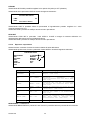
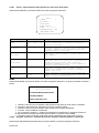
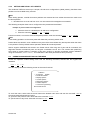
4.5
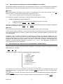
IMPOSTAZIONE DELLE MODALITÀ DI FUNZIONAMENTO TRAMITE MENU
Si può accedere al menu di impostazione delle modalità di funzionamento utilizzando il seguente comando
dalla tastiera Sch. 1092/620.
CALL + 90 + ON
A questo punto, appare la seguente schermata di primo livello del menu.
THERA 5
> 1 Language
English
2 Dome Information
3 Display Options
4 Control Options
5 Diagnostic Options
6 Camera Options
7 Function Programming
IRIS CLOSE to Exit
Per scorrere le voci del menu basta agire sui tasti freccia posizionandosi in corrispondenza della voce di
menu da selezionare: a questo punto, usare il comando OPEN per entrare nel menu di secondo livello
selezionato.
Una volta entrati in un menu, per tornare indietro al menu di livello precedente sarà sufficiente selezionare il
comando CLOSE
Per uscire completamente dai menu di qualunque livello è sufficiente selezionare il comando CLOSE.
DS1092-090
18
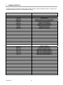
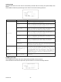
Opzione
Valore
Spiegazione
Language
ENGLISH
I menu sono solo in lingua inglese.
Dome Information
Menu relativo alle informazioni sul prodotto (vedi par. 4.5.1).
Display Informations
Menu relativo alle visualizzazioni (vedi par. 4.5.2).
Control Options
Menu relativo alle programmazioni principali (vedi par. 4.5.3).
Diagnostic Options
Menu relativo alle programmazioni secondarie (vedi par. 4.5.4).
Camera Options
Menu relativo alla impostazione del testo da associare alla dome
(vedi par. 4.5.5).
Function Programming
Menu relativo alla programmazione e memorizzazione dei Preset,
Vector Scan , Pattern , Motion e Allarmi.
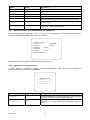
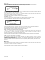
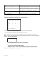
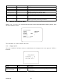
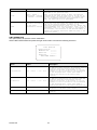
4.5.1
MENU RELATIVO ALLE INFORMAZIONI SUL PRODOTTO
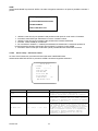
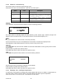
Dal menu di primo livello, scegliendo <DOME INFORMATION> si ottengono le informazioni relative al modulo,
protocollo, baudrate,all’indirizzo della dome, alla versione.
Dome Information
Camera
Protocol
Baudrate
9600
Dome NO
Version
X.XX
IRIS CLOSE to Exit
SAMSUNG
Pelco D
3
Queste informazioni non possono essere variate in questo menu.
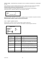
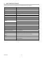
4.5.2
Menu relativo alle visualizzazioni
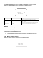
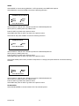
Il menu <DISPLAY OPTIONS> permette di abilitare/disabilitare i testi che devono comparire in
corrispondenza delle varie funzioni di THERA 5.
Display Options
Coordinates
ON
Start-Up Scr Msg ON
IRIS CLOSE To Exit
Opzione
Valore
Spiegazione
COORDINATES
ON/OFF
Abilitazione/disabilitazione della visualizzazione delle coordinate
di pan e tilt corrispondenti alle immagini visualizzate.
START-UP SCR MSG
ON/OFF
Abilitazione/disabilitazione della visualizzazione delle informazioni
sul prodotto al momento della accensione della Dome (vedi par.
4.5.1).
DS1092-090
19
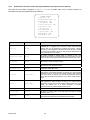
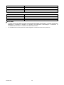
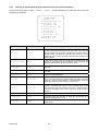
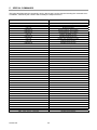
4.5.3
Impostazioni da menu relative alle programmazioni principali (Control Options)
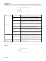
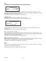
Dal menu di primo livello, scegliendo <CONTROL OPTIONS> e relativi sotto menu si ottiene l’accesso ai
principali menu per la programmazione di THERA 5
CONTROL OPTIONS
>1 Auto Flip
ON
2 Proportional Speed
ON
3 Pan Reverse
OFF
4 Tilt Reverse
OFF
5 Vector Scan Still
OFF
6 Auto Focus
PTZ
7 Auto AE
PTZ
8 VectorScan AF
ON
9 +2 Tilt Limit
OFF
10 Speed limit
OFF
IRIS CLOSE to Exit
Opzione
Valore
Spiegazione
Auto Flip
On/off
Se questa modalità è attivata (ON), è possibile seguire la
traiettoria di un soggetto che si muove e passa sotto la dome
agendo solo con lo spostamento verticale del joystick. Questo
perché una volta raggiunta la posizione verticale, la dome compie
un movimento automatico di pan di 180 gradi per riposizionarsi e
poter riprendere la corsa del tilt.
Proportional Speed
ON/OFF
Se questa modalità è attivata (ON), la velocità di pan e tilt
applicata da tastiera è proporzionale allo zoom impostato, in modo
che la velocità di movimento diminuisca all’aumentare dello zoom.
Pan Riverse
ON/OFF
Se questa modalità è attivata (ON), i comandi del joistick relativi
alla funzione di pan risultano invertiti.
Tilt Riverse
ON/OFF
Se questa modalità è attivata (ON), i comandi del joistick relativi
alla funzione di tilt risultano invertiti.
VectorScan Still
ON/OFF
FUNZIONE NON ABILITATA
ON/OFF/PTZ/Z
Se attivato con ON la Dome eseguirà in automatico il controllo
della messa a fuoco delle immagini. Se attivato con PTZ la Dome
eseguirà la messa a fuoco solo durante l’utilizzo delle funzioni
Pan, Tilt e Zoom. Se attivato con Z la Dome eseguirà la messa a
fuoco delle immagini esclusivamente con l’utilizzo della funzione
zoom.
Auto AE
ON/OFF/PTZ/Z
Se attivato con ON la Dome eseguirà in automatico il controllo
della esposizione delle immagini. Se attivato con PTZ la Dome
eseguirà il controllo solo durante l’utilizzo delle funzioni Pan, Tilt e
Zoom. Se attivato con Z la Dome eseguirà il controllo
esclusivamente con l’utilizzo della funzione zoom.
VectorScan AF
ON/OFF
FUNZIONE NON ABILITATA
+2 Tilt Limit
ON/OFF
Se attivo con ON il limite di tilt della Dome aumenta di 2gradi
passando da 0° a -2°.
Speed limit
ON/OFF
Se attivata con ON, questa funzione riduce della metà la velocità
di spostamento della dome precedentemente impostata.
Auto Focus
DS1092-090
20
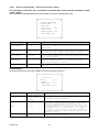
4.5.4
IMPOSTAZIONI DA MENU RELATIVE ALLE PROGRAMMAZIONI PRINCIPALI (DIAGNOSTIC
OPTIONS)
Dal menu di primo livello, scegliendo <DIAGNOSTIC OPTIONS> e relativi sotto menu si ottiene l’accesso ai
principali menu per la gestione e la diagnostica di THERA 5
Diagnostic Options
>1 Clear Memory
2 Restore Def Setting
3 Color System
PAL
4 Dome Reset
IRIS CLOSE to Exit
Opzione
Valore
Spiegazione
Se attivata la funzione per mezzo del tasto OPEN e premendo
nuovamente il tasto OPEN per conferma, vengono cancellate tutte
le memorizzazioni eseguite dell’utente relative ai Preset e
VectorScan Still. (Sono escluse dalla cancellazione tutte le
personalizzazioni impostate dall’utente relative alle impostazioni di
utilizzo della Dome).
Clear Memory
Se attivato esegue un ripristino di tutti i dati di default presenti
sulla Dome ad esclusione dei dati memorizzati dall’utente relativi
ai preset e ai VectorScan Still.
Utilizzare solo il sistema PAL.
Esegue un RIAVVIO del dispositivo senza perdere le impostazioni
eseguite dall’utente. La dome esegue un riposizionamento.
Restore Def Setting
Color System
PAL/NTSC
Dome Reset
4.5.5
IMPOSTAZIONI DA MENU RELATIVE ALLE PROGRAMMAZIONI SECONDARIE (CAMERA
OPTIONS)
Dal menu di primo livello, scegliendo <CAMERA OPTIONS> e relativi sotto menu si ottiene l’accesso ai menu
della telecamera per la programmazione del modulo camera.
4.5.6
DESCRIZIONE DEL SISTEMA DEI MENU
Una volta impartito il comando di accesso al menu apparirà a monitor la finestra iniziale di accessoal menù
OSD del modulo camera.
E’ possibile selezionare le voci per mezzo dei tasti “freccia” della tastiera
o
.
Una volta selezionata la voce voluta, è possibile variare il parametro utilizzando il tasto
scegliendo fra le
opzioni disponibili visualizzabili premendo ripetutamente il tasto
.
Per confermare le impostazioni volute selezionare END e premere Il tasto CLOSE.
Il simbolo
indica che selezionando la voce ad esso abbinato si accederà ad un successivo sottomenu
nel quale sarà possibile eseguire ulteriori variazioni.
MAIN SETUP
CAM TITLE
WHITE BAL
BACKLIGHT
MOTION DET
FOCUS
EXPOSURE
SPECIAL
RESET
END
DS1092-090
ON
ATW
LOW
ON
21
Opzione
4.5.7
4.5.7.1
Valore
Spiegazione
Questa opzione permette di nominare la dome
utilizzando fino ad un massimo di 20
caratteri. (Vedi oltre)
CAM TITLE
ON OFF
WHITE BAL
MANUAL AWC-SET Questa opzione consente di selezionare la
modalità di bilanciamento del bianco. (Vedi
ATW
oltre)
BACKLIGHT
LOW MIDDLE
HIGH OFF
MOTION DET
ON OFF
SELEZIONARE SOLO OFF (per configurare la
funzione Motion Detector utilizzare la
funzione
presente
nel
menù
principale
Function Programming)
FOCUS
/
Questa opzione consente di selezionare i
parametri relativi al funzionamento zoom
della dome. (Vedi oltre)
EXPOSURE
/
Questa opzione consente
regolazioni
relative
dell’ottica. (Vedi oltre)
SPECIAL
/
Questa
opzione
consente
di
funzioni speciali. (Vedi oltre)
RESET
/
Questa funzione consente di ripristinare
tutte le variazioni eseguite dall’utente
riportando la dome allo stato iniziale.
END
/
Questa opzione consente di uscire dal menu
principale e tornare al menù OSD.
Questa opzione consente di selezionare il
livello di compensazione di controluce.
(Vedi oltre)
di eseguire le
all’esposizione
attivare
DESCRIZIONE DELLE VOCI DI MENU
Cam title – assegnazione di un nome alla dome
Questa funzione consente di “nominare” la dome e di visualizzare il nome a monitor nella posizione preferita.
Selezionando questa voce di menu è possibile scegliere fra le opzioni ON e OFF.
Selezionando ON e premendo il tasto OPEN si accede al seguente sottomenu nel quale è possibile
nominare la dome.
ABCDEFGHIJKLMNO
PQRSTUVWXYZabcd
efghijklmnopqrs
tuvwxyz01234567
89 ()<>-/#*!?,.
CLR POS END
Utilizzare i tasti “freccia” per spostarsi sopra il carattere voluto.
Premere il tasto OPEN per confermarlo.
Selezionare CLR per cancellare i caratteri selezionati.
Per cancellare solo uno o più caratteri posizionarsi per mezzo dei tasti “freccia” sopra lo “spazio” nella
posizione successiva al numero 9 e precedente al simbolo (
e premere OPEN.
Selezionando POS e premendo OPEN si accede al seguente sottomenu:
CAM TITLE POS SETUP
to Locate, then SET
Utilizzando I tasti “freccia” è possibile definire la posizione sullo schermo nel quale apparirà il nome della
dome.
Premere CLOSE per tornare al menu precedente.
Selezionare END e premere CLOSE per tornare al menu precedente.
4.5.7.2 White bal – bilanciamento del bianco
DS1092-090
22
Questa funzione consente di selezionare la modalità del bilanciamento del bianco.
Selezionando questa voce di menu è possibile scegliere fra le opzioni MANUAL, AWC-SET e ATW.
Opzione
Valore
Spiegazione
MANUAL
RED ÷ BLUE
Questa
opzione
consente
di
regolare
manualmente il bilanciamento del bianco.
AWC-SET
/
Auto White Balance: regolazione automatica
per interni da utilizzare in ambienti con
bassa luce o in caso di presenza di luci
fluorescenti
ATW MODE
OUTDOOR INDOOR
Auto
Tracking
White
Mode:
regolazione
automatica
basata
sulla
rilevazione
dell’ambiente
circostante
(esterno
o
interno).
END
/
Consente di uscire dal sottomenu.
MANUAL
Selezionando MANUAL e premendo il tasto OPEN si accede al seguente sottomenu:
WHITE BAL MANUAL SETUP
RED
BLUE
END
35 ■■■■■■■█■■■
55 ■■■■█■■■■■■
Questa opzione consente di regolare manualmente il bilanciamento del bianco in condizioni di luce estreme
(inquadrature con grandi varietà di colori ma assenza di bianco, in ambienti chiusi con illuminazione
artificiale fluorescente colorata,ecc.);
Nota Bene
Si consiglia di non usare questa modalità se non strettamente necessario.
Utilizzare i tasti “freccia” per spostarsi sopra la voce desiderata e incrementare o decrementare il valore
indicato.
Eseguite le regolazioni posizionarsi sopra END e premere CLOSE per tornare al menu precedente.
AWC-SET
Selezionando AWC-SET e premendo il tasto OPEN si attiva il bilanciamento del tipo Auto White Bilance,
tipicamente per interni.
Premere CLOSE per tornare al menu precedente.
Selezionare END e premere CLOSE per tornare al menu precedente.
ATW
Selezionando ATW e premendo il tasto OPEN si accede al seguente sottomenu:
WHITE BAL MODE
ATW MODE
END
OUTDOOR
Per mezzo dei tasti “freccia” è possibile variare l’indicazione OUTDOOR (per esterni) in INDOOR (per
interni).
Premere CLOSE per tornare al menu precedente.
Selezionare END e premere CLOSE per tornare al menu precedente.
DS1092-090
23
4.5.7.3
Backlight – BLC – compensazione controluce
Un oggetto inquadrato con forte luce proveniente da dietro solitamente appare scuro e poco visibile rispetto
al resto dell’immagine. La funzione BLC permette di ovviare a questo inconveniente ed ottenere una buona
compensazione.
Selezionando questa voce di menu è possibile scegliere fra le opzioni OFF (disattivo), LOW (bassa),
MIDDLE (media) e HIGH (alta).
4.5.7.4
Focus– impostazioni dello zoom
Questa funzione consente di accedere al sottomenu di impostazioni delle regolazioni della dome.
Selezionando questa voce di menu e premendo OPEN si accede al seguente sottomenu:
FOCUS SETUP
MODE
ZOOM TRK
ZOOM SPEED
D-ZOOM
DISP ZOOM MAG
ZOOM POS INIT
LENS INIT
END
Opzione
Valore
Spiegazione
MODE
MANUAL ÷ AUTO ÷ Consente di selezionare il modo di messa a
fuoco della dome. (Vedi oltre)
ONE-PUSH
ZOOM TRK
ON ÷ OFF
Se l’opzione selezionata è ON l’ottica
della dome eseguirà in continuo la messa a
fuoco automatica.
FAST ÷ SLOW
Consente di selezionare la velocità di
messa a fuoco della dome. La funzione NON
è
attivabile
se
l’opzione
MODE
è
selezionata in AUTO e l’opzione ZOOM TRK è
selezionata in ON. (Vedi oltre)
ON ÷ OFF
Consente di abilitare/disabilitare lo zoom
digitale. In caso di abilitazione è
possibile
regolare
il
valore
in
percentuale dello zoom (x2 min. – x10
max.). (Vedi oltre)
DISP ZOOM MAG
ON ÷ OFF
Se l’opzione selezionata è ON viene
visualizzato a monitor l’impostazione di
zoom attiva ( x2 min. – x10 max). Con la
funzione
D-ZOOM
attiva
è
possibile
arrivare a x100 max.
ZOOM POS INIT
ON ÷ OFF
FUNZIONE NON ATTIVA
ZOOM SPEED
D-ZOOM
DS1092-090
MANUAL
ON
FAST
OFF
ON
ON
LENS INIT
La
funzione
esegue
l’inizializzazione
dell’ottica della dome. (Vedi oltre)
END
Consente di uscire dal sottomenu.
24
MODE
Selezionando MODE è possibile scegliere fra le opzioni MANUAL (manuale), AUTO (automatica) e ONEPUSH (una pressione).
Selezionando MANUAL e premendo OPEN si accede al seguente sottomenu:
ZOOM/FOCUS POS SETUP
:TELE
:NEAR
:WIDE
:FAR
Press SET to Return
Utilizzando I tasti “FOCUS” e “ZOOM” è possibile eseguire le regolazioni desiderate.
TELE (avvicina l’immagine); WIDE (allarga l’immagine); NEAR (vicino); FAR (lontano).
Premere CLOSE per tornare al menu precedente.
Selezionare END e premere CLOSE per tornare al menu precedente.
Selezionando AUTO e premendo OPEN si accede al seguente sottomenu:
ZOOM POS SETUP
:TELE
:WIDE
Press SET to Return
Utilizzando I tasti “FOCUS” e “ZOOM” è possibile eseguire le regolazioni desiderate.
TELE (avvicina l’immagine); WIDE (allarga l’immagine).
Premere CLOSE per tornare al menu precedente.
Selezionare END e premere CLOSE per tornare al menu precedente.
Selezionando ONE-PUSH (ad ogni pressione dei tasti corrisponde una variazione) e premendo OPEN si
accede al seguente sottomenu:
ZOOM/FOCUS POS SETUP
:TELE
:NEAR
:WIDE
:FAR
Press SET to Return
Utilizzando I tasti “FOCUS” e “ZOOM” è possibile eseguire le regolazioni desiderate.
TELE (avvicina l’immagine); WIDE (allarga l’immagine); NEAR (vicino); FAR (lontano).
Premere CLOSE per tornare al menu precedente.
Selezionare END e premere CLOSE per tornare al menu precedente.
ZOOM SPEED
Selezionando ZOOM SPEED è possibile scegliere fra le opzioni FAST (veloce) e SLOW (lento).
DS1092-090
25
D-ZOOM
Selezionando D-ZOOM è possibile scegliere fra le opzioni ON (attivo) e OFF (disattivo).
Selezionando ON e premendo OPEN si accede al seguente sottomenu:
D-ZOOM LIMIT SETUP
LIMIT
END
X2
Press SET to Return
Selezionando LIMIT è possibile variare la percentuale di ingrandimento potendo scegliere fra i valori
compresi tra X2 fino a X10.
Selezionare END e premere CLOSE per tornare al menu precedente.
LENS INIT
Selezionando LENS INIT e premendo i tasti OPEN o CLOSE si esegue la taratura dell’ottica con
ottimizzazione della messa a fuoco iniziale della dome.
Selezionare END e premere CLOSE per tornare al menu precedente.
4.5.7.5
Exposure– esposizione
Questa funzione consente di variare le funzioni relative all’ottica della dome.
Selezionando questa voce di menu e premendo il tasto OPEN si accede al seguente sottomenu:
EXPOSURE SETUP
BRIGHTNESS
IRIS
SHUTTER
AGC
SSNR
SENS-UP
END
41 ■■■■■■■█■■■
MANUAL
MANUAL
NORMAL
HIGH
OFF
Opzione
Valore
Spiegazione
BRIGHTNESS
0 ÷ 100
Consente di regolare la luminosità delle
immagini. (Vedi oltre)
IRIS
AUTO ÷ MANUAL
Consente
di
selezionare
il
tipo
di
regolazione
desiderata
per
l’apertura/chiusura dell’iris della dome.
(Vedi oltre)
SHUTTER
MANUAL ÷ A.FLK
Consente
di
determinare
il
tempo
di
esposizione del CCD per la regolazione
dell’apertura dell’otturatore della dome.
(Vedi oltre)
AGC
NORMAL ÷ HIGH ÷ Consente di selezionare un valore dell’AGC
OFF
o disattivarlo. (Vedi oltre)
SSNR
LOW ÷ MIDDLE
HIGH ÷ OFF
SENS-UP (DSS)
AUTO ÷ OFF
Consente
di
attivare/disattivare
la
funzione di variazione della sensibilità
(DSS)
della
dome
in
funzione
della
variazione della luce. (Vedi oltre)
END
/
Consente di uscire dal sottomenu.
÷ Consente di selezionare un valore di
riduzione del rumore o di disattivarlo.
(Vedi oltre)
BRIGHTNESS - LUMINOSITA’
Selezionando BRIGHTNESS e premendo i tasti “freccia” è possibile variare la percentuale di luminosità.
DS1092-090
26
IRIS - IRIDE
Selezionando IRIS è possibile scegliere fra le opzioni MANUAL (manuale) e AUTO (automatico).
Selezionando MANUAL e premendo OPEN si accede al seguente sottomenu:
IRIS MANUAL SETUP
IRIS VAL
END
85 ■■■■■■■█■■■
Selezionando IRIS VAL e premendo i tasti “freccia” è possibile variare la percentuale di apertura dell’iride
della dome scegliere fra i valori compresi tra 1 a 100.
Questa regolazione deve essere variata solo in condizioni estreme di utilizzo della dome. Per tutte le altre
applicazioni si consiglia di utilizzare la modalità AUTO.
Selezionare END e premere CLOSE per tornare al menu precedente.
SHUTTER – OTTICA
Selezionando SHUTTER è possibile scegliere fra le opzioni MANUAL (manuale) e A.FLK.
Selezionando MANUAL e premendo OPEN si accede al seguente sottomenu:
SHUTTER MANUAL SETUP
SHUTTER VAL
1/50
END
Press SET to Return
Selezionando SHUTTER VAL e premendo i tasti “freccia” è possibile variare la percentuale di apertura
dell’ottica della dome potendo scegliere fra valori che variano fra “1/50” e “fix 2x”.
Selezionare END e premere CLOSE per tornare al menu precedente.
AGC – CONTROLLO AUTOMATICO DEL GUADAGNO
L’AGC è un circuito elettronico che provvede ad amplificare il segnale video quando questo cade sotto ad
una certa soglia, cioè quando la luminosità dell’immagine è scarsa. Il risultato è una visione più chiara in
ambienti poco illuminati che senza l’AGC risulterebbero scure.
Selezionando AGC è possibile scegliere fra le opzioni NORMAL(normale), HIGH (alta) e OFF (disattiva).
SSNR – CIRCUITO RIDUZIONE DEL RUMORE
La tecnologia di riduzione del rumore SSNR (Samsung Super Noise Reduction) consente di ottenere
immagini più pulite e nitide senza effetti fantasma o neve, eliminando gli elevati livelli di rumore generati da
condizioni di scarsa illuminazione.
Selezionando SSNR è possibile scegliere fra le opzioni LOW (bassa), MIDDLE (media), HIGH (alta) e OFF
(disattiva).
Nota Bene
Questa regolazione deve essere variata solo in condizioni estreme di utilizzo della dome. Per tutte le altre
applicazioni si consiglia di utilizzare la modalità OFF.
Selezionare END e premere CLOSE per tornare al menu precedente.
DS1092-090
27
SENS-UP (DSS) – VARIAZIONE DELLA SENSIBILITA’ DELLA DOME IN FUNZIONE DELLA VARIAZIONE
DI LUCE
Questo dispositivo consente di effettuare riprese di scene in condizioni di scarsa luminosità. Alla graduale
diminuzione della luminosità, corrisponde una diminuzione dei frame per secondo (numero di
immagini/secondo) aumentando la sensibilità della dome.
Selezionando SENS-UP è possibile scegliere fra le opzioni AUTO (automatica) e OFF (disattivo).
Selezionando AUTO e premendo OPEN si accede al seguente sottomenu:
SENS-UP LIMIT SETUP
LIMIT
END
X2
Press SET to Return
Selezionando LIMIT e premendo i tasti “freccia” è possibile variare la sensibilità di esposizione dell’ottica
della dome potendo scegliere fra valori che variano fra X2 fino a X128.
Selezionare END e premere CLOSE per tornare al menu precedente.
4.5.7.6
Special– regolazioni speciali
Questa funzione consente di variare le funzioni relative ai parametri della dome.
Selezionando questa voce di menu e premendo il tasto OPEN si accede al seguente sottomenu:
SPECIAL SETUP
USER PRESET
PRIVACY
DAY/NIGHT
SYNC
COMM ADJ
IMAGE ADJ
END
OFF
OFF
AUTO1
INT
Opzione
DS1092-090
Valore
Spiegazione
USER PRESET
ON ÷ OFF
FUNZIONE ATTUALMENTE NON DISPONIBILE.
NON USARE
PRIVACY
ON ÷ OFF
FUNZIONE ATTUALMENTE NON DISPONIBILE.
NON USARE
DAY/NIGHT
Consente di selezionare la modalità di
COLOR ÷ B/W ÷ variazione del funzionamento della dome in
AUTO1 ÷ AUTO2 ÷
funzione delle condizioni di utilizzo.
EXT
(Vedi oltre)
SYNC
INT
Indica che il metodo di sincronizzazione è
interno e non può essere variato.
COMM ADJ
/
NON SELEZIONARE
Per evitare la perdita di comunicazione tra
dome e dome NON VARIARE QUESTO PARAMETRO.
IMAGE ADJ
/
Selezionando questa voce, si accede al
relativo sottomenu nel quale è possibile
selezionare
le
opzioni
relative
alla
modalità di visualizzazione delle immagini.
(Vedi oltre)
END
/
Consente di uscire dal sottomenu.
28
DAY/NIGHT - VARIAZIONE DEL FUNZIONAMENTO DELLA DOME IN FUNZIONE DELLA VARIAZIONE DI
LUCE PRESENTE SULLA SCENA
La dome, che normalmente riprende le immagini a colori, in condizioni di scarsa illuminazione, commuta
automaticamente il suo funzionamento da “colore” a “bianco/nero”, in questo modo viene ottimizzata la
qualità delle immagini riprese.
Selezionando DAY/NIGHT è possibile scegliere fra le opzioni AUTO1 (automatica), AUTO2 (automatica),
EXT, COLOR e B/W (bianco e nero).
AUTO1: Questa opzione consente alla dome di variare la funzione di mutazione automatica DAY/IGHT con
una variazione minima di luce pari a 40LUX.
AUTO2: Questa opzione consente alla dome di variare la funzione di mutazione automatica DAY/IGHT con
una variazione minima di luce pari a 20LUX.
EXT: FUNZIONE ATTUALMENTE NON DISPONIBILE.
COLOR: Con questa opzione le immagini riprese dalla dome risultano sempre a colori.
B/W: Con questa opzione le immagini riprese dalla dome risultano sempre in bianco/nero.
IMAGE ADJ
Selezionando IMAGE ADJ e premendo OPEN si accede al seguente sottomenu:
IMAGE SETUP
FREEZE
H-REV
V-REV
SHARPNESS
COLOR GAIN
END
OFF
OFF
OFF
ON
56 ■■■■■■■█■■■
Opzione
Valore
Spiegazione
FREEZE
ON ÷OFF
Selezionando ON viene attivata la funzione
di “Fermo Immagine”.
H-REV (MIRROR)
ON ÷ OFF
Consente
di
orizzontalmente.
capovolgere
l’immagine
V-REV (MIRROR)
/
Consente
di
verticalmente.
capovolgere
l’immagine
SHARPNESS
ON ÷ OFF
Selezionando ON è possibile accedere al
relativo sottomenu nel quale è possibile
variare la definizione delle immagini.
(Vedi oltre)
COLOR GAIN
0 ÷ 100
Consente di regolare l’intensità dei colori
delle immagini.
END
/
Consente di uscire dal sottomenu.
SHARPNESS - DEFINIZIONE
Selezionando SHARPNESS e premendo OPEN si accede al seguente sottomenu:
SHARPNESS LEVEL
LEVEL
END
8 ■■■■■■■█■■■
Press SET to Return
DS1092-090
29
Selezionando LEVEL e premendo i tasti “freccia” è possibile variare la definizione delle immagini potendo
scegliere fra valori che variano fra 0 fino a 31.
Selezionare END e premere CLOSE per tornare al menu precedente.
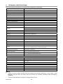
4.5.8
IMPOSTAZIONI DA MENU RELATIVE ALLE PROGRAMMAZIONI (FUNCTION PROGRAMMING)
Dal menu di primo livello, scegliendo <FUNCTION PROGRAMMING> e relativi sotto menu si ottiene l’accesso
ai menu successivi per la programmazione di THERA 5.
FUNCTION PROGRAMMING
Preset
Program VectorScan
Pattern
Sector Setup
Masking Zone
Motion
Alarm In Programming
IRIS CLOSE to Exit
>1
2
3
4
5
5
6
Opzione
Valore
Spiegazione
Preset
Number ÷ Set Preset
÷ Call Preset÷Delete
Preset ÷ Name÷
Display
Consente di accedere a tutte le funzioni relative ai Preset
quali memorizzazione,selezione,nomenclatura e cancellazione.
(Vedi oltre)
Program
VectorScan
Number ÷ Program a
VectorScan ÷ Run a
VectorScan ÷ Delete
a VectorScan
Consente di accedere a tutte le funzioni relative ai VectorScan
quali memorizzazione,selezione e cancellazione. (Vedi oltre)
Pattern
Number ÷ Name ÷
Program a Pattern ÷
Delete a Pattern ÷
Name Display
Consente di accedere a tutte le funzioni relative ai Pattern
quali memorizzazione,selezione,nomenclatura e cancellazione.
(Vedi oltre)
Number÷Name ÷ Pan
Sector Setup Start POS ÷ Pan End
POS ÷ Tilt Start POS
÷ Name Display
Number ÷ Mask Edit ÷
Masking Zone Mask Display
Consente di definire una determinate zona e di nominarla potendo
cosi riconoscerla ogni qualvolta si ripresenti a video. (Vedi
oltre)
La funzione Masking Zone permette di specificare fino a 4 zone
di riservatezza che mascherano determinate aree della scena alla
vista dall’operatore. Una Masking Zone appare sul monitor come
un rettangolo di dimensioni precedentemente impostati
dall’utente. (Vedi oltre)
Motion
Park Action ÷ Power
On Action ÷ Limit
Operation
Consente di accedere a tutte le funzioni relative alla
movimentazione della dome. (Vedi oltre)
Alarm In
Programming
Channel Number ÷
Label Edit ÷ Label
Display ÷ Action
Setup ÷ Channel
Enable
Consente di accedere alle funzioni di allarme abbinabili
dall’utente a specifiche funzioni della dome. (Vedi oltre)
DS1092-090
30
4.5.8.1
Preset - memorizzazione della posizione e dello zoom della dome
Selezionando PRESET e premendo OPEN si accede al seguente sottomenu:
Preset
Number
1
Set Preset
Call Preset
Delete Preset
Name
------------AlaName Display
OFF
IRIS CLOSE to Exit
>1
2
3
4
5
6
Opzione
Valore
Spiegazione
Number
1-50 ÷ 64-77 ÷ 102165
Questa opzione consente di identificare i preset che è
possibile memorizzare. E’ possibile selezionare un
massimo di 128 preset
Set Preset
/
Questa opzione consente di memorizzare il preset. E’
necessario inquadrare l’immagine che si vuole abbinare
al preset e premere CLOSE. La memorizzazione viene
confermata dalla scritta STORED
Call Preset
/
Questa operazione consente di richiamare un preset
memorizzato. (Viene richiamato il preset indicato alla
voce “Number”)
Delete Preset
/
Questa operazione consente di cancellare un preset
memorizzato. Una volta selezionato il preset che si
desidera cancellare premere OPEN e confermare
nuovamente ripremendo il tasto. In caso contrario è
possibile uscire premendo CLOSE.
Name
/
Questa operazione consente di nominare i preset
memorizzati. Premendo due volte OPEN è possibile
accedere alla schermata che consente di nominare il
preset. (Vedi oltre)
Name Display
ON/OFF
Questa operazione se selezionata in ON consente di
vedere a monitor il mome precedentemente memorizzato e
associato al preset visualizzato
NAME
Selezionando NAME e premendo OPEN si accede al seguente sottomenu nel quale è possibile nominare il
preset :
-
----------------
0123456789ABCDEFRGHIJKLMN
OPQRSTUVWXYZIRIS CLOSE When Done
Utilizzare i tasti freccia per spostarsi nella posizione nella quale si vuole inserire il carattere.
Premere il tasto OPEN per selezionare il numero o la lettera voluta.
Utilizzare i tasti freccia per spostarsi nella posizione del carattere desiderato.
Premere il tasto OPEN per confermarlo.
Per cancellare il carattere o i caratteri precedentemente selezionati è necessario spostarsi in
corrispondenza del simbolo posizionato dopo la lettera Z e premere il tasto OPEN.
Premere il tasto CLOSE per confermare quanto precedentemente selezionato ed uscire.
4.5.8.2 Program vectorscan – definizione percorso costituito da preset, pattern e vectorscan
Selezionando PROGRAM VECTORSCAN e premendo OPEN si accede al seguente sottomenu:
DS1092-090
31
Opzione
Valore
Spiegazione
Number
1 ÷ 6
Questa opzione consente di identificare i VectorScan
che si vogliono memorizzare. E’ possibile selezionare
un massimo di 6 VectorScan
Program a VectorScan
/
Questa opzione consente di definire le operazioni che
devono essere eseguite dal VectrorScan selezionato
(max 16). E’possibile stabilire per ogni operazione il
tipo di azione, il numero a cui è abbinata, la velocità
di spostamento e il tempo di sosta. (Vedi oltre)
Run a VectorScan
/
Questa opzione consente di far partire il VectorScan
selezionato
Delete a VectorScan
/
Questa opzione consente di cancellare il VectorScan
selezionato premendo due volte il tasto OPEN
PROGRAM A VECTORSCAN
Selezionando Program a VectorScan e premendo OPEN si accede al seguente sottomenu nel quale è
possibile definire i parametri del VectorScan che si vuole memorizzare:
PROGRAM VECTORSCAN
1
2
3
4
5
6
7
8
Name
Pr
-
Num
1
-
SP
5
-
Dwell
3
-
IRIS CLOSE When Done
Utilizzare i tasti freccia per spostarsi nella posizione nella quale si vuole inserire il dato.
1 – è il numero di azione; è possibile inserire un massimo di 16 azioni.
Name – è il tipo di azione; selezionare con il tasto OPEN Pr (Preset), Vs (VectorScan),Pt (Pattern).
Num – è il numero riferito alla precedente memorizzazione dell’azione prescelta; premere il tasto OPEN per
accedere alla schermata di selezione.
1~50 64~77 102~165
___∟
0123456789
Premere i tasti freccia per spostasi nella posizione desiderata.
Premere il pulsante OPEN per accedere alla selezione numerica.
Premere i tasti freccia per selezionare il numero desiderato.
Premere il tasto OPEN per confermarlo.
Premere il tasto CLOSE alla fine della selezione.
Spostarsi sul simbolo ∟ e premere il tasto OPEN per tornare alla schermata precedente.
SP – è la velocità di spostamento fra una azione e l’altra; è possibile scegliere fra valori di 1 a 9, premere il
tasto OPEN per selezionare la velocità desiderata.
DS1092-090
32
Dwell – è il tempo di sosta prima che venga attivata la successiva azione; è possibile scegliere fra valori di 1
a 9; premere il tasto OPEN per selezionare il tempo di sosta desiderato.
Nota Bene
Affinché il numero di azione sia attiva è necessario inserire tutti i parametri richiesti e precedentemente
elencati.
4.5.8.3
Pattern – definizione percorso programmabile
Selezionando PATTERN e premendo OPEN si accede al seguente sottomenu:
Pattern
Number
1
Name
Program a Pattern
Run a Pattern
Delete a Pattern
Name Display
OFF
IRIS CLOSE to Exit
>1
2
3
4
5
6
Opzione
Valore
Spiegazione
Number
1 ÷ 3
Questa opzione consente di identificare i Pattern
(Percorsi) che si vogliono memorizzare. E’ possibile
selezionare un massimo di 3 Pattern
Name
/
Questa operazione consente di nominare i pattern
memorizzati. Premendo due volte OPEN è possibile
accedere alla schermata che consente di battezzare il
pattern. (Vedi oltre)
Program a Pattern
/
Questa opzione consente di memorizzare i pattern.
Posizionandosi per mezzo dei tasti freccia sulla
inquadratura di partenza da memorizzare. Premere OPEN e
muoversi seguendo il percorso che si vuole memorizzare,
alla fine del percorso premere nuovamente CLOSE per
confermare la memorizzazione del patttern.
Run a Pattern
/
Questa opzione consente di far partire il pattern
selezionato
Delete a Pattern
/
Questa opzione consente di cancellare il pattern
selezionato premendo due volte il tasto OPEN
Name Display
ON/*OFF
Questa operazione se selezionata in ON consente di
vedere a monitor il nome precedentemente memorizzato e
associato al pattern visualizzato
DS1092-090
33
NAME
Selezionando NAME e premendo OPEN si accede al seguente sottomenu nel quale è possibile nominare il
preset :
-
----------------
0123456789ABCDEFRGHIJKLMN
OPQRSTUVWXYZIRIS CLOSE When Done
Utilizzare i tasti freccia per spostarsi nella posizione nella quale si vuole inserire il carattere.
Premere il tasto OPEN per selezionare il numero o la lettera voluta.
Utilizzare i tasti freccia per spostarsi nella posizione del carattere desiderato.
Premere il tasto OPEN per confermarlo.
Per cancellare il carattere o i caratteri precedentemente selezionati è necessario spostarsi in
corrispondenza del simbolo posizionato dopo la lettera Z e premere il tasto OPEN.
Premere il tasto CLOSE per confermare quanto precedentemente selezionato ed uscire.
4.5.8.4
Sector setup – definizione settori
La dome viene limitata nel movimento all’interno dei settori stabiliti dall’utente.
Selezionando SECTOR SETUP e premendo OPEN si accede al seguente sottomenu:
Sector Setup
Number
1
Name
---------Pan Start POS
Pan End POS
Tilt Start POS
Tilt End POS
Name Display
ON
IRIS CLOSE to Exit
>1
2
3
4
5
6
7
Opzione
Valore
Spiegazione
Number
1 ÷ 8
Questa opzione consente di identificare i
settori che si vogliono memorizzare. E’
possibile selezionare un massimo di 8 settori
Name
/
Questa operazione consente di nominare i settori
memorizzati. Premendo due volte OPEN è possibile
accedere alla schermata che consente di nominare
il settore. (Vedi oltre)
0,0 ÷ 359,9
Questa opzione consente di memorizzare le
coordinate di partenza del settore relative al
PAN. Premendo OPEN e posizionandosi per mezzo
dei tasti freccia sulla inquadratura di partenza
da memorizzare, è possibile vedere a monitor
anche le coordinate relative alla inquadratura
visualizzata. Premere nuovamente OPEN per
confermare la memorizzazione del punto di
partenza del settore.
Pan Start POS
DS1092-090
÷ 0,0 ÷ 90,0
34
Pan End POS
Tilt Start POS
0,0 ÷ 359,9
0,0 ÷ 359,9
Tilt End POS
0,0 ÷ 359,9
Name Display
ON/OFF
÷ 0,0 ÷ 90,0
Questa opzione consente di memorizzare le
coordinate finali del settore relative al PAN.
Premendo OPEN e posizionandosi per mezzo dei
tasti freccia sulla inquadratura fine settore da
memorizzare, è possibile vedere a monitor anche
le coordinate relative alla inquadratura
visualizzata. Premere nuovamente OPEN per
confermare la memorizzazione del punto di fine
del settore.
÷ 0,0 ÷ 90,0
Questa opzione consente di memorizzare le
coordinate di partenza del settore relative al
TILT. Premendo OPEN e posizionandosi per mezzo
dei tasti freccia sulla inquadratura di partenza
da memorizzare, è possibile vedere a monitor
anche le coordinate relative alla inquadratura
visualizzata. Premere nuovamente OPEN per
confermare la memorizzazione del punto di
partenza del settore.
Questa operazione se selezionata in ON consente
di vedere a monitor il nome precedentemente
memorizzato e associato al settore visualizzato
NAME
Selezionando NAME e premendo OPEN si accede al seguente sottomenu nel quale è possibile nominare il
preset :
-
----------------
0123456789ABCDEFRGHIJKLMN
OPQRSTUVWXYZIRIS CLOSE When Done
Utilizzare i tasti freccia per spostarsi nella posizione nella quale si vuole inserire il carattere.
Premere il tasto OPEN per selezionare il numero o la lettera voluta.
Utilizzare i tasti freccia per spostarsi nella posizione del carattere desiderato.
Premere il tasto OPEN per confermarlo.
Per cancellare il carattere o i caratteri precedentemente selezionati è necessario spostarsi in
corrispondenza del simbolo posizionato dopo la lettera Z e premere il tasto OPEN.
Premere il tasto CLOSE per confermare quanto precedentemente selezionato ed uscire per
tornare al menù precedente.
Selezionare ON alla voce Name Display per visualizzare il nome del settore sul monitor.
DS1092-090
35
4.5.8.5
Masking zone- zona di mascheramento
Permette di escludere all’operatore la visione di parti delle immagini riprese e visualizzate a monitor.
Selezionando MASKING ZONE e premendo OPEN si accede al seguente sottomenu:
Masking Zone
>1 Number
1
2 Mask Edit
3 Mask Display
OFF
IRIS CLOSE to Exit
Opzione
Valore
Spiegazione
Number
1 ÷ 4
Questa opzione consente di selezionare le
quattro zone di mascheramento disponibili.
Mask Edit
/
Questa opzione consente di definire la grandezza
e la posizione della zona di mascheramento.
(Vedi oltre)
Mask Display
ON/OFF
Questa opzione se selezionata in ON consente di
rendere attiva la funzione visualizzando a
monitor la zona di mascheramento.
MASK EDIT
Selezionando MASK EDIT e premendo si visualizza a monitor la zona di riservatezza selezionata
precedentemente con Number.
Utilizzando i tasti freccia è possibile spostare la zona nella posizione desiderata.
Utilizzando i tasti TELE e WIDE è possibile variare le dimensioni della zona orizzontalmente.
Utilizzando i tasti NEAR e FAR è possibile variare le dimensioni della zona verticalmente.
OSSERVAZIONI SULLA ZONA DI RISERVATEZZA
È consigliabile utilizzare zone di riservatezza leggermente più grandi dell’area da nascondere.
Le zone di riservatezza possono essere solo di forma rettangolare.
4.5.8.6 Motion – azionamenti automatici
Selezionando MOTION e premendo OPEN si accede al seguente sottomenu:
MOTION
>1 Park Action
2 Power On Action
3 Limit Operation
IRIS CLOSE to Exit
DS1092-090
36
PARK ACTION
La PARK ACTION è l’azione che viene eseguita automaticamente dopo un periodo (PARK TIME) di inattività
della Dome.
Selezionando PARK ACTION e premendo IL TASTO FRECCIA DESTRA si accede al seguente sottomenu:
Park Action
>1Action
_________
2 Number
_________
3 Park Time
_________
IRIS CLOSE to Exit
Opzione
Valore
Spiegazione
None
Al termine dell’azione eseguita dall’utente, non viene
eseguita nessuna nuova azione in modo automatico.
Preset
Al termine dell’azione eseguita dall’utente, la dome si
posizionerà su uno dei 128 preset memorizzati
precedentemente e selezionato dall’utente dopo il tempo
stabilito (PARK TIME) prima che l’azione abbia inizio.
Vector Scan
Al termine dell’azione eseguita dall’utente, la dome
avvierà uno dei 6 VectorScan memorizzati
precedentemente e selezionato dall’utente dopo il tempo
stabilito (PARK TIME) prima che l’azione abbia inizio.
Pattern
Al termine dell’azione eseguita dall’utente, la dome
avvierà uno dei 3 Pattern memorizzati precedentemente e
selezionato dall’utente dopo il tempo stabilito (PARK
TIME) prima che l’azione abbia inizio.
PanScan
Al termine dell’azione eseguita dall’utente, la dome
eseguirà una scansione orizzontale fra due punti
precedentemente memorizzata dopo il tempo stabilito
(PARK TIME) prima che l’azione abbia inizio.
AutoScan
Al termine dell’azione eseguita dall’utente, la dome
esegue una scansione orizzontale di 360° dopo il tempo
stabilito (PARK TIME) prima che l’azione abbia inizio.
RepeatLast
Al termine dell’azione eseguita dall’utente, la dome
riprenderà semplicemente l’azione che stava facendo
prima di essere interrotta unitamente al tempo che deve
trascorrere prima che l’azione abbia inizio. (vedi
sotto).
Number
Variabile in
funzione del valore
selezionato su “Park
Action”
Questa opzione consente di definire specificatamente
quale singola azione si vuole attivare. Il numero
selezionabile della singola azione varia in funzione
della azione precedentemente selezionata (da 1 a 165
esclusi i non programmabili per i Preset; da 1 a 6 per
i VectorScan; da 1 a 3 per i Pattern; 1 per PanScan; 1
per AutoScan). La selezione del numero desiderato è
possibile premendo il tasto OPEN e accedendo alla
relativa schermata.
Park Time
Tempo in secondi
Tempo dopo il quale l’azione automatica (PARK ACTION)
viene avviata
Park Action
POWER ON ACTION
La POWER ON ACTION è l’azione che viene eseguita automaticamente all’accensione della Dome.
Selezionando POVER ON ACTION e premendo IL TASTO FRECCIA DESTRA si accede al seguente
sottomenu:
Power On Action
>1Action
_________
2 Number
_________
IRIS CLOSE to Exit
DS1092-090
37
Opzione
Action
Number
Valore
Spiegazione
None ÷ Preset ÷
VectorScan ÷ Pattern
÷ PanScan ÷ AutoScan
Questa opzione consente di selezionare una delle azioni
descritte nella tabella precedente.
NOTA: se l’opzione selezionata sarà None, nel momento
dell’accensione verrà eseguita l’ultima funzione svolta
dalla dome prima dello spegnimento, o il Park Time nel
caso in cui prima dello spegnimento non fossero state
richieste alla dome funzioni programmate).
Variabile in
funzione del valore
selezionato su
“Action”
Questa opzione consente di definire specificatamente
quale singola azione si vuole attivare. Il numero
selezionabile della singola azione varia in funzione
della azione precedentemente selezionata (da 1 a 165
esclusi i non programmabili per i Preset; da 1 a 6 per
i VectorScan; da 1 a 3 per i Pattern; 1 per PanScan; 1
per AutoScan). La selezione del numero desiderato è
possibile premendo il tasto OPEN e accedendo alla
relativa schermata.
LIMIT OPERATION
Questa opzione consente di memorizzare le coordinate del settore.
Selezionando LIMIT OPERATION e premendo IL TASTO FRECCIA DESTRA si accede al seguente
sottomenu:
Limit Operation
>1Start Position ________
2End Position
________
3Direction
________
4Operation
________
IRIS CLOSE to Exit
.
Opzione
Start Position
Valore
Spiegazione
0,0 ÷ 359,9
÷ 0,0 ÷ 90,0
Questa opzione consente di memorizzare le
coordinate di inizio del settore relative al PAN
e TILT. Premendo OPEN e posizionandosi per mezzo
dei tasti freccia sulla inquadratura fine
settore da memorizzare, è possibile vedere a
monitor anche le coordinate relative alla
inquadratura visualizzata. Premere nuovamente
OPEN per confermare la memorizzazione del punto
di inizio del settore.
÷ 0,0 ÷ 90,0
Questa opzione consente di memorizzare le
coordinate finali del settore relative al PAN e
TILT. Premendo OPEN e posizionandosi per mezzo
dei tasti freccia sulla inquadratura fine
settore da memorizzare, è possibile vedere a
monitor anche le coordinate relative alla
inquadratura visualizzata. Premere nuovamente
OPEN per confermare la memorizzazione del punto
di fine del settore.
End Position
0,0 ÷ 359,9
Direction
Left ÷ Right
Questa opzione consente di selezionare la
direzione di movimento della dome. (verso
sinistra Left, verso destra Right).
Operation
ON ÷ OFF
Questa opzione se settata su ON consente di
rendere attiva la funzione.
DS1092-090
38
4.5.8.7
Alarm in programming – azioni collegate agli allarmi
QUESTA FUZIONE E’ DISPONIBILE SOLO SE SONO PRESENTI IL POWER BOX 1092/628 E/O LE SCHEDE
ALLARME SUPPLEMENTARI 1092/685
Selezionando ALARM IN PROGRAMMING e premendo OPEN si accede al seguente sottomenu:
Alarm In Programming
>1Channel Number
1
2 Label Edit
____
3 Label Display
OFF
4 Action Setup
5 Channel Enable
OFF
IRIS CLOSE to Exit
Opzione
Valore
Spiegazione
Channel Number
1 ÷ 16
Questa opzione consente di selezionare il contatto di
allarme che si vuole attivare. La disponibilità di 16
contatti di allarme è possibile solo con l’uso di due
schede di allarme.
Label Edit
____________
Questa operazione consente di nominare i contatti di
allarme memorizzati. Premendo due volte OPEN è possibile
accedere alla schermata che consente di battezzare i
contatti prescelti.
Label Display
ON ÷ OFF
Questa opzione se settata in ON, consente di visualizzare
sul monitor il nome precedentemente memorizzato del
contatto di allarme attivatosi a seguito di un evento.
Selezionando questa opzione e premendo il tasto OPEN si
accede al relativo sottomenu nel quale è possibile
impostare i parametri di attivazione (vedi oltre).
Action Setup
Channel Enable
ON ÷ OFF
Questa opzione, se settata in ON, abilita le funzioni
precedentemente descritte.
ACTION SETUP
Selezionando ACTION SETUP e premendo il tasto OPEN si accede al seguente sottomenu:
Action Setup
>1Action
2 Number
3 Dwell Time
IRIS CLOSE
DS1092-090
39
---------------------to Exit
Opzione
Valore
Spiegazione
Action
Preset÷VectorScan÷
Patter÷PanScan÷
AutoScan
Questa opzione consente di selezionare una delle azioni
descritte nella tabella delle PARK ACTION.
Number
1 ÷ 165
Questa opzione consente di definire specificatamente
quale singola azione si vuole attivare. Il numero
selezionabile della singola azione varia in funzione
della azione precedentemente selezionata (da 1 a 165
esclusi i non programmabili per i Preset; da 1 a 6 per
i VectorScan; da 1 a 3 per i Pattern; 1 per PanScan; 1
per AutoScan). La selezione del numero desiderato è
possibile premendo il tasto OPEN e accedendo alla
relativa schermata.
Dwell Time
1 ÷ 999
Questa opzione consente di definire il tempo (in
secondi) di attivazione dell’uscita di allarme.
DS1092-090
40
4.6
IMPOSTAZIONI HARDWARE (DIP-SWITCH)
4.6.1
IMPOSTAZIONE DELLA DOME
Per eseguire le impostazioni di indirizzo,di baud rate e protocollo di comunicazione è necessario rimuovere
la cupola estera e la cupola interna della dome procedendo nel seguente modo:
1. Ruotare in senso antiorario la cupola esterna per circa ¼ di giro per sbloccarla dalla sede.
2. Ruotare in senso antiorario la cupola interna per circa ¼ di giro per sbloccarla dalla sede.
3. Rimosse le due parti è possibile accedere ai dipswitch situati internamente alla dome.
DIP-SWITCH
4.
5.
6.
Eseguite le regolazioni volute utilizzando il piccolo cacciavite in dotazione.
Posizionare la cupola interna sul supporto facendo coincidere le alette di tenuta della cupola stessa con
i fori presenti su supporto e ruotare in senso orario sino al blocco.
Posizionare la cupola esterna sul supporto e ruotarla in senso orario fino al blocco.
4.6.2
IMPOSTAZIONE DELL’INDIRIZZO
La dome THERA 5 viene impostata di fabbrica con indirizzo 1.
Per variare l’indirizzo in funzione dei dispositivi collegati, agire sul dipswitch situato sulla scheda elettronica
della dome seguendo l’esempio riportato in figura.
IMPOSTAZIONE DI DEFAULT
ON
1
ON
2
3
4
5
6
7
1
8
1
DS1092-090
2
3
4
5
6
7
8
128
2
64
4
32
8
16
41
Assegnazione dell’indirizzo della dome con protocollo pelco D
A ciascuna dome si può assegnare uno fra 255 indirizzi possibili agendo sugli 8 interruttori del dip-switch
della Serie 2. L’indirizzo assegnato può essere determinato dalla tabella seguente.
INDIRIZZO
DIP-SWITCH SERIE 2
2
3
4
5
6
7
8
OFF
OFF
OFF
OFF
OFF
OFF
OFF
OFF
1
ON
OFF
OFF
OFF
OFF
OFF
OFF
OFF
2
OFF
ON
OFF
OFF
OFF
OFF
OFF
OFF
0 (NON USARE)
1
3
ON
ON
OFF
OFF
OFF
OFF
OFF
OFF
4
OFF
OFF
ON
OFF
OFF
OFF
OFF
OFF
5
ON
OFF
ON
OFF
OFF
OFF
OFF
OFF
6
OFF
ON
ON
OFF
OFF
OFF
OFF
OFF
7
ON
ON
ON
OFF
OFF
OFF
OFF
OFF
8
OFF
OFF
OFF
ON
OFF
OFF
OFF
OFF
9
ON
OFF
OFF
ON
OFF
OFF
OFF
OFF
10
OFF
ON
OFF
ON
OFF
OFF
OFF
OFF
11
ON
ON
OFF
ON
OFF
OFF
OFF
OFF
12
OFF
OFF
ON
ON
OFF
OFF
OFF
OFF
13
ON
OFF
ON
ON
OFF
OFF
OFF
OFF
14
OFF
ON
ON
ON
OFF
OFF
OFF
OFF
15
ON
ON
ON
ON
OFF
OFF
OFF
OFF
16
OFF
OFF
OFF
OFF
ON
OFF
OFF
OFF
17
ON
OFF
OFF
OFF
ON
OFF
OFF
OFF
18
OFF
ON
OFF
OFF
ON
OFF
OFF
OFF
19
ON
ON
OFF
OFF
ON
OFF
OFF
OFF
20
OFF
OFF
ON
OFF
ON
OFF
OFF
OFF
21
ON
OFF
ON
OFF
ON
OFF
OFF
OFF
22
OFF
ON
ON
OFF
ON
OFF
OFF
OFF
23
ON
ON
ON
OFF
ON
OFF
OFF
OFF
24
OFF
OFF
OFF
ON
ON
OFF
OFF
OFF
25
ON
OFF
OFF
ON
ON
OFF
OFF
OFF
26
OFF
ON
OFF
ON
ON
OFF
OFF
OFF
27
ON
ON
OFF
ON
ON
OFF
OFF
OFF
28
OFF
OFF
ON
ON
ON
OFF
OFF
OFF
246
OFF
ON
ON
OFF
ON
ON
ON
ON
247
ON
ON
ON
OFF
ON
ON
ON
ON
248
OFF
OFF
OFF
ON
ON
ON
ON
ON
249
ON
OFF
OFF
ON
ON
ON
ON
ON
250
OFF
ON
OFF
ON
ON
ON
ON
ON
251
ON
ON
OFF
ON
ON
ON
ON
ON
252
OFF
OFF
ON
ON
ON
ON
ON
ON
253
ON
OFF
ON
ON
ON
ON
ON
ON
254
OFF
ON
ON
ON
ON
ON
ON
ON
255
ON
ON
ON
ON
ON
ON
ON
ON
DS1092-090
42
4.6.3
IMPOSTAZIONI DI BAUD RATE
E’ possibile selezionare la velocità comunicazione (baud rate) variando la configurazione dei dipswitch
(numero 1 e 2) situato sulla scheda elettronica della dome, seguendo le posizioni indicate:
ON
1
22
3
4
BAUD RATE
1
4.6.4
PROTOCOLLO
2400
4800
9600
19200
ON
ON
ON
ON
22
3
4
1
2
3
2
1
4
3
4
1
2
3
4
IMPOSTAZIONI DI PROTOCOLLO DI COMUNICAZIONE
E’ possibile selezionare il protocollo di comunicazione variando la configurazione dei dipswitch (numero 3 e
4) situato sulla scheda elettronica della dome, seguendo le posizioni indicate:
ON
1
22
3
4
BAUD RATE
PROTOCOLLO
PELCO D
PELCO P
ON
ON
1
22
3
1
4
22
3
4
NOTA BENE
Si consiglia la selezione del protocollo PELCO D alla baud-rate di 9600 bps per garantire il corretto
funzionamento dei prodotti della famiglia THERA con i prodotti compatibili del catalogo Urmet Domus
DS1092-090
43
5
COMANDI SPECIALI
I comandi speciali, eseguibili da tastiera sotto descritti, possono essere realizzati inviando il comando CALL
o PRESET seguito dai numeri che ne identificano l’azione.
COMANDO DA TASTIERA
FUNZIONE
CALL 51
Memorizza la velocità del Panscan
PRESET 51
Avvia il Preset Tour di default
CALL 52
Abilita il PanScan
PRESET 52
Memorizza il punto di partenza del PanScan
PRESET 53
Memorizza il punto di arrivo del PanScan
CALL 55
Abilita la funzione Backlight
PRESET 55
Disabilita la funzione Backlight
CALL 56
Abilita la funzione Day/Night auto
CALL 58
Abilita la funzione Zoom
PRESET 58
Disabilita la funzione Zoom
CALL 60
Abilita la funzione Auto Iris
CALL 80
Abilita la partenza del primo pattern
CALL81
Abilita la partenza del secondo pattern
CALL 82
Abilita la partenza del terzo pattern
CALL 83
Abilita la partenza del primo VectorScan
CALL 84
Abilita la partenza del secondo VectorScan
CALL 85
Abilita la partenza del terzo VectorScan
CALL 86
Abilita la partenza del quarto VectorScan
CALL 87
Abilita la partenza del quinto VectorScan
CALL 88
Abilita la partenza del sesto VectorScan
CALL 90
Abilita il menù
CALL 91
Richiama l’ultima posizione della dome mantenuta per
almeno 5 secondi.
PRESET 94
Esegue il reset della dome
CALL 101
Esegue la scansione su 360°
CALL 171
Abilita l’azione abbinata all’allarme 1
CALL 172
Abilita l’azione abbinata all’allarme 2
CALL 173
Abilita l’azione abbinata all’allarme 3
CALL174
Abilita l’azione abbinata all’allarme 4
CALL 175
Abilita l’azione abbinata all’allarme 5
CALL 176
Abilita l’azione abbinata all’allarme 6
CALL 177
Abilita l’azione abbinata all’allarme 7
CALL 178
Abilita l’azione abbinata all’allarme 8
CALL 179
Abilita l’azione abbinata all’allarme 9
CALL 180
Abilita l’azione abbinata all’allarme 10
CALL 181
Abilita l’azione abbinata all’allarme 11
CALL 182
Abilita l’azione abbinata all’allarme 12
CALL 183
Abilita l’azione abbinata all’allarme 13
CALL 184
Abilita l’azione abbinata all’allarme 14
CALL 185
Abilita l’azione abbinata all’allarme 15
CALL 186
Abilita l’azione abbinata all’allarme 16
PRESET 1÷50 – 64÷77 – 102÷165
Memorizza i preset
CALL 1÷50 – 64÷77 – 102÷165
Richiama i preset memorizzati
DS1092-090
44
6
CARATTERISTICHE TECNICHE
Sono qui riassunte le principali caratteristiche tecniche della telecamere Sch.1092/602.
Caratteristiche generali
Valore
Peso
1000 g.
Dimensioni x H
122 x193 mm
Tensione d’alimentazione
24VAC
Consumo massimo
6W
Grado di protezione
IP66
Temperatura di utilizzo
-25 +60°C
Caratteristiche della minidome
Valore
Minidome
Modulo Samsung con CCD Sony ¼“
Ottica
10x, f3.8-38mm f.1.8
Zoom
100x (10x Optical, 10x Digitale)
Sensibilità
Indirizzi disponibili
Colore 0,7 Lux/F1.8; 0.005 Lux/F1.8 (Sens-up)
Bianco/Nero 0,02 Lux/F1.8
1 - 256
Rapporto segnale rumore
>50 dB
Risoluzione
Colore 500 TVL – B/N 570 TVL
Messa a fuoco
Automatica/Manuale
Sincronizzazione
Interna
Standard video
PAL
Range di rotazione asse orizzontale
360° continui
Range di rotazione asse verticale
0 – 90° (funzione pivot)
Numero di Preset
181
Numero di Preset programmabili
128
Funzioni
Repeat Last, Auto Scan, Pan Scan, Frame Scan;Sens-up, Auto Iris, Auto flip, On
screen menu, Titolazione Preset, On Screen Display (OSD)
VectorScan (sequenze di funzioni e Preset
attivabili)
6 VectorScan x 16 funzioni
Pattern (percorsi memorizzabili)
3 (fino a 120 secondi memorizzabili caduna)
In – Out Allarmi
16 allrmi gestibili da menù (8 In – 2 Out inclusi nel Power Box + 8 In 1 Out da scheda
allarmi supplementare)
Azioni abbinabili agli allarmi
VectorScan – Pattern – Auto Scan Pan - Preset
DS1092-090
45
Caratteristiche meccaniche
Valore
Velocità manuale di spostamento orizzontale
0.1 240°/s
Velocità manuale di spostamento verticale
0.1 120°/s
Velocità in preset
300°/s
Controllo remoto
Valore
Interfaccia
RS485
Protocollo
Pelco-D
Data rate
2400bps, 4800bps, 9600bps (selezionabili tramite dip-switch)
NOTA BENE
Il modulo camera di THERA 5 utilizza la tecnologia DSS (Digital Slow Shutter). In questo modulo detto
Sens-Up le impostazioni rallentano la frequenza dei fotogrammi dell’immagine e aumentano la
sensibilità della minidome in condizioni di scarsa illuminazione.
Le caratteristiche tecniche possono essere soggette a variazione senza alcun preavviso.
DS1092-090
46
ENGLISH
INDEX
1
GENERAL INFORMATION ................................................................................................................... 48
1.1
Product Description .............................................................................................................. 48
1.2
Package Opening ................................................................................................................. 48
1.2.1
2
3
3.2.1
3.2.2
3.2.3
4
Package Contents ............................................................................................................................... 48
1.3
Structure of this manual ....................................................................................................... 48
IMPORTANT SAFETY NOTES ............................................................................................................. 49
INSTALLATION PROCEDURES........................................................................................................... 51
3.1
Basic system configuration for the use of thera 5 ................................................................ 51
3.2
Installation Types.................................................................................................................. 51
Wall mounting...................................................................................................................................... 52
Requirements for connection cables ................................................................................................... 58
Power supply cables dimensions ........................................................................................................ 58
OPERATING MODE .............................................................................................................................. 59
4.1
Operation at power-up.......................................................................................................... 59
4.2
Use with command keypad .................................................................................................. 59
4.2.1
4.2.2
4.3
4.4
Keypad ref. 1092/620 command syntax .............................................................................................. 60
Types of commands activated with the keypad ................................................................................... 60
Dome selection..................................................................................................................... 61
Dome movement operations ................................................................................................ 61
4.4.1
4.4.2
4.4.3
4.4.4
4.4.5
4.5
Pan and tilt functions ........................................................................................................................... 61
Zoom functions.................................................................................................................................... 62
Focus change functions ...................................................................................................................... 62
Iris opening functions .......................................................................................................................... 62
Setting and recall of presets ................................................................................................................ 63
Operation modes setting via the menu................................................................................. 63
4.5.1
4.5.2
4.5.3
4.5.4
4.5.5
4.5.6
4.5.7
Product information menu ................................................................................................................... 64
Display options .................................................................................................................................... 64
Settings of main programming procedures via the menu (Control Options) ........................................ 65
Settings of main programming via the menu (diagnostic options) ....................................................... 66
Settings of secondary programming via the menu (camera options)................................................... 66
Menu structure description .................................................................................................................. 66
Menu items description ....................................................................................................................... 67
4.5.7.1
4.5.7.2
4.5.7.3
4.5.7.4
4.5.7.5
4.5.7.6
4.5.8
Menu settings concerning programming (function programming)........................................................ 75
4.5.8.1
4.5.8.2
4.5.8.3
4.5.8.4
4.5.8.5
4.5.8.6
4.5.8.7
4.6
Preset – storage of dome position and zoom ............................................................................................... 76
Program vectorscan – definition of a path made by preset, pattern and vectorscan .................................... 77
Pattern – definition of the configurable path ................................................................................................. 78
Sector setup – definition of sectors ............................................................................................................... 79
Masking zone ................................................................................................................................................ 81
Motion – automatic operations ...................................................................................................................... 81
Alarm in programming – actions associated to alarms ................................................................................. 84
Hardware settings (dip-switch) ............................................................................................. 85
4.6.1
4.6.2
4.6.3
4.6.4
5
6
Cam title – assigning a name to the dome.................................................................................................... 67
White bal – white balancing .......................................................................................................................... 68
Backlight – BLC – backlight compensation ................................................................................................... 68
Focus– zoom adjustment .............................................................................................................................. 69
Exposure ....................................................................................................................................................... 71
Special– special adjustments........................................................................................................................ 73
Dome setting ....................................................................................................................................... 85
Address setting.................................................................................................................................... 85
Baud rate setting ................................................................................................................................. 87
Communication protocol settings ........................................................................................................ 87
SPECIAL COMMANDS ......................................................................................................................... 88
TECHNICAL SPECIFICATIONS ........................................................................................................... 89
DS1092-090
47
1
GENERAL INFORMATION
Dear Customer,
Thank your for purchasing this product.
This document shows how to install and use the URMET Domus THERA 5 Ref.1092/602.
Read this manual which contains information for correct, safe use carefully.
Keep this manual at hand so that you can refer to it when needed.
1.1
PRODUCT DESCRIPTION
The minidome Ref. 1092/602 offers many features providing excellent video quality and control capability;
high quality colour images can be captured during the day and black/white images during the night.
The minidome must be combined with a control keypad, for ex. Ref. 1092/620, Ref.1092/690, Ref.1092/691
or Ref.1092/692. The keypad allows pan/tilt and zoom control at a variable speed, to supervise remote areas
in professional CCTV systems.
1.2
PACKAGE OPENING
Check that the packing and the contents are not visibly damaged. Contact the retailer immediately if parts are either
missing or damaged. Do not attempt to use the device in this case. Send the product back in its original packing if it is
damaged.
1.2.1
PACKAGE CONTENTS
No.1 camera module.
No.1 wall mounting bracket.
No.1 rubber gasket for wall mounting bracket.
No.1 kit containing No. 1 screwdriver, No. 3 screws with washer for fixing the minidome, No. 1 O-ring
for wall mounting bracket, No. 1 metal junction ring.
No.1 dedicated power supply unit.
No.1 connection cable.
Instructions manual.
NOTE
The provided accessories are subject to change without notice.
1.3
STRUCTURE OF THIS MANUAL
This document consists of the following fundamental parts:
Warnings and important safety notes.
Procedures for installing the camera, useful accessories and instructions for connecting all components
to an integrated video system.
Instructions for using the camera in combination with a control panel and advanced option management.
Overview of technical specifications.
Each chapter deals with one of these topics.
DS1092-090
48
2
IMPORTANT SAFETY NOTES
The following important notes must be followed carefully to work the Thera 5 Ref.1092/602 camera and
respective accessories in total safety.
The term “video system” here means a camera and all components needed for its operation (e.g., power,
leads, supports, control board and more).
Read the instructions
Read all safety rules and instructions carefully before starting to work the video system.
Keep the instructions
Keep the safety notes and instructions for use for future reference.
Respect the warnings
Pay attention to all warnings on the camera and in the instruction manual.
Follow the instructions
Follow the instructions in the instruction manual to the letter.
Cleaning
Disconnect all electrical parts from the mains before cleaning.
Attachments
Do not use attachments other than those recommended in the instruction manual because this could cause
risks for the products.
Water and humidity
Do not use any part of the video system near water, i.e. bathtubs, wash basins, sinks, tubs, on damp
surfaces, near swimming pools, etc.
Accessories
Do not position the camera on unsteady trolleys, stands, brackets or tables. The camera could fall and
severely injury adults and children in addition to seriously damaging the product. Follow the instruction
manual and only use the recommended accessories for the camera for installation and set-up.
Ventilation
Never position the camera near or over radiators or sources of heat. Check that the area is suitably
ventilated before installing the camera inside partially closed areas (such as recesses, bookshelves and
shelves). Refer to the instructions shown in the installation manual.
Electrical power
A switch for performing maintenance operations on the camera must be included.
Connect the camera only to the electrical power supply shown on the ratings plate. Contact your retailer if in
doubt.
Power lead protection
Lay the power wires keeping them from being trodden on or squeezed by objects placed on top of them. Pay
particular attention to leads near plugs, screws and the product outlet.
Lightening
Disconnect the power lead and the wiring to protect the camera during electrical storms or when it is left
unattended and not used for a long time. This will prevent damage to the video system in the event of
lightening or electrical line overload.
Overloads
Do not overload the electrical power and the extensions to prevent the risk of fire or electrocution.
Penetration of liquid and objects
Do not insert objects of any kind through the camera openings to avoid touch live parts: fire and electrocution
risk. No not pour any kind of liquid on the device.
DS1092-090
49
Repairs
Do not attempt to repair the camera (or any other part of the video system) yourself because opening or
removing the lids may expose you to high voltage and other dangers. Always contact a qualified service
technician.
Damage requiring professional assistance
Disconnect the video system from the power mains and call qualified service personnel in the following
cases:
If the power lead or plug is damaged.
If liquid or foreign objects accidentally penetrate inside the device.
If the device was exposed to rain or water.
If the device is not working properly although the instructions in the manual are respected.
In this case, only use the controls described in the manual because improper use of other controls
could make the situation worse. More work may be required by the qualified technician to restore
normal working conditions of the device.
If the device was dropped, subjected to heavy shocks or if the camera packaging was damaged.
If the device performance changes considerably.
Replacement of parts
Make sure that the service technician uses the spare parts specified by the manufacturer or spare parts with
equivalent characteristics when replacements are required. Unauthorised replacements can cause fires,
electrical shocks and other dangers.
Safety checks
After any servicing intervention or repair to the video system, ask the technician to run a safety check to
ensure that everything is working safety.
Precautions
To protect the camera, avoid installing and using it in direct sunlight and keep it away from rain and
dust.
Do not touch the zoom lens with your fingers. If needed, use a soft cloth and methylated spirit to
remove traces of dust.
Apply a specific cap to protect the zoom lens when the camera is not in use.
Do not point the camera towards the sun.
Do not point the camera towards sources of bright light. Bright light, like that from a spotlight, can
cause dimming and blurs. A vertical line may appear on the screen. This does not indicate a
problem.
Install the camera away from video interference. The pictures could present interference if the leads
are arranged near a TV set or other device. Either move the leads or re-install the device to solve the
problem.
Privacy and Copyright
The 1092/602 camera a CCTV system devices. Recording of imagines is subject to the laws in force
in your country. Recording of images protected by copyright is forbidden.
Product users shall be responsible for checking and respecting all local rules and regulations
concerning monitoring and recording video signals. The manufacturing SHALL NOT BE LIABLE for
use of this product not in compliance with the laws in force.
DS1092-090
50
3
INSTALLATION PROCEDURES
This section contain detailed instructions for installing Urmet Domus 1092/602 camera. These instructions
assume that the installer has a good knowledge of installation techniques and is capable of adopting safe
installation methods.
3.1
BASIC SYSTEM CONFIGURATION FOR THE USE OF THERA 5
The minidome THERA 5 has an embedded receiver which decodes the commands coming from the control
keypad Ref. 1092/620 (see chapter 4.2). For a correct operation, at least one control keypad is needed. This
keypad manages the configuration of operating parameters and the function of pan (360° continuous) and tilt
(180°), motorized zoom, recall and programming of pre-defined sequences of THERA 5.
3.2
INSTALLATION TYPES
Two solutions are available for installing THERA 5.
Wall mounting with standard bracket.
Wall mounting with kit composed by bracket and connection power box IP66 Ref. 1092/628.
Note
Regardless of the installation type, it is suggested to:
Connect a switch for minidome maintenance operations.
Check that on terminals of RS - 485 lines suitable termination resistors (120 Ω ¼ W), not provided,
are connected.
DS1092-090
51
3.2.1
WALL MOUNTING
Before starting installation, check that all devices to be connected are not powered.
Place on the wall mounting bracket the provided o-ring, in the suitable seat.
Fit the dome connection cable, provided, into the bracket, until it comes out on the opposite side.
Put the provided junction ring in the upper seat of the dome, taking care that the three holes on the
dome match the three holes on the ring, using the references on both the sides.
Connect the cable terminal block to the dome terminal block, as shown in the figure.
DS1092-090
52
Fix the bracket to the dome using the provided round head screws with the rubber washer, by screwing
them tightly in the holes on the bracket sides.
Fix the dome to the wall, taking care that the cable goes through the slot in the bracket, or make another
hole on the wall, in order to allow the passage of the cable. The diameter of this hole must be large
enough for the passage of the connectorized cable.
Fix tightly the dome to the wall, using the 4 holes in the bracket base, with 4 M6 screws, not provided.
The following figure shows the hole interaxis in mm.
70
100
120
50
No. 4 holes 8
DS1092-090
53
WALL MOUNTING WITH POWER BOX REF. 1092/628 (not provided)
Before starting installation, check that all devices to be connected are not powered.
Make the holes on the support base and fix the Power Box using the 4 holes on the device ends.
With a Phillips screwdriver unscrew the 4 screws on the Power Box front unit in order to open it and
make the following connections.
UNSCREW TO OPEN
UNSCREW TO OPEN
When the Power Box is open, make the connections for the RS485 line. Insert in the largest hole on the
lower side, provided with grommet, a 2-wire cable of suitable length and section (see Requirements for
connection cables). This cable must be connected to terminal pins AA (+) and BB (-) on the card.
Connect the video signal RG cable by putting the cable of suitable length and type (see Requirements
for connection cables) in the largest hole provided with grommet, present on the lower side of the Power
Box (the same used for RS485 line) and connect it to the BNC connector present in the cable provided
with the Power Box.
DS1092-090
54
Connect 230Vac power supply by putting the cable of suitable length and type (see Requirements for
connection cables) in the smallest hole provided with grommet, present on the lower side of the Power
Box and connect it to the terminal pins on the card, after removing the protection lid.
Put again the protection lid.
Close again the Power Box.
Fit the dome connection cable, provided, into the bracket, until it comes out on the opposite side.
Fix the bracket to the Power Box using the 4 screws, as shown in the figure.
Place on the wall mounting bracket the provided rubber o-ring, in the suitable seat.
RUBBER O-RING
CONNECTION
CABLE
LOCKING
SCREWS
DS1092-090
LOCKING
SCREWS
55
Put the provided junction ring in the upper seat of the dome, taking care that the two holes on the dome
match the two holes on the ring, using the references on both the sides.
Connect the cable terminal block to the dome terminal block, as shown in the figure.
Fix the bracket to the dome using the three provided round head screws with the rubber washer, by
screwing them tightly in the holes on the bracket sides.
USE THE PROVIDED SCREWS TO
FIX THE MINIDOME TO THE
BRACKET
DS1092-090
56
CONNECTIONS
Connect the provided cable to the dome using terminal blocks.
Connect the second end of the cable to the video device, using the BNC male connector.
Connect the two wires of RS485 with a terminal block or welding them to the keypad (Ref. 1092/620)
wiring junction box, observing polarity: ORANGE + (positive) - YELLOW – (negative).
Connect the two power supply wires with the terminal block or welding them to the wires of the provided
power supply unit (it is not necessary to observe polarity).
If the dome is the last device of RS485 line (see RS485 LINE LOGIC CONNECTION), connect a 120
Ohm ¼ w resistor, not provided, in parallel to the RS485 line.
Make connections as shown in “CONNECTIONS DETAILS”.
Connect the power supply unit to the mains.
CONFIGURATION
Connection cable
Dome
supply
power
COAX
IF THE DEVICE IS THE LAST OF THE
LINE, CONNECT A 120 OHM ¼ W
RESISTOR
RS485
RS485 LINE LOGIC CONFIGURATION.
KEYPAD
JUNTION BOX
DOME
TERMINATION
Connect the resistor
Figure 2: BASIC CONFIGURATION
Note
If several Domes are connected, it is suggested to use a cascade configuration, with “in/out” connections on
each device. However, the sum of the lengths of the single segments of the RS485 line must not exceed
1200m.
Remember to always connect the termination resistor on the last Dome of the line.
DS1092-090
57
3.2.2
REQUIREMENTS FOR CONNECTION CABLES
Three types of cables are required:
1. The video cable, used to bring a standard composite video signal to the remote surveillance
station. Usually a 75 Ohm coax cable is used.
2. The power supply cable for the minidome THERA 5 (24Vac power supply unit). To define
cable dimensions, see “Power supply cables dimensions” in this manual.
3. RS485 cable, used for commands sent by the keypad to THERA 5. A 2-wire, twisted,
unshielded cable is needed. The suggested diameter is 0,64 mm (22AWG).
3.2.3
POWER SUPPLY CABLES DIMENSIONS
Pay attention to the correct dimension of the cable which provides 24V power supply voltage for THERA 5. If
the cable diameter is too little, the voltage dropout can cause malfunction. The following formula shows the
voltage provided to THERA 5 according to the cable dimension.
VD VT
PD RW DW
VT 500
Where:
VD
VT
PD
RW
DW
= Voltage on THERA 5.
= Transformer voltage.
= THERA 5 power consumption in Watt.
= Cable resistance in Ohm per meter (see the table below).
= Cable length (in meters) between THERA 5 and the power supply unit.
Wire diameter (mm)
Resistance (Ohm/m)
2,60
3,35/1000
2,05
5,32/1000
1,63
8,46/1000
1,29
13,42/1000
1,02
21,36/1000
0,81
34,12/1000
0,64
54,14/1000
Wire diameter and resistance values
The following table shows the suggested lengths for the cable of a THERA 5.
Wire diameter (mm)
Cable max. length for outdoor
version (m)
2,60
200
2,05
125
1,63
80
1,29
50
1,02
30
0,81
20
0,64
10
Power supply cable max. length
DS1092-090
58
4
OPERATING MODE
4.1
OPERATION AT POWER-UP
At the first power-up, the dome operates with the factory default configurations. If settings are changed, they
are permanently stored and will be available also for future dome power-up. Notice that at any time settings
can be restored to default values using the suitable menu item.
During power-up, the dome operates as follows:
1. The dome performs a calibration phase, displaying in the OSD menu (On Screen Display) a
message with the following information: used protocol, communication parameters, dome address
and software version.
Check that data are those required for operation.
Otherwise, see the section of this manual concerning dome settings (chapter 4.7).
PTOL: PELCO-D
COMM: 9600
ADDR: 01
SW version X.XX
Note
Write down the SW version if technical assistance is required.
2. Once the calibration phase is completed, the dome goes in waiting mode and operates according to
settings configured in the operation modes menu in the item POWER UP ACTION under the menu
<DOME SETTINGS1 • POWER UP>. The dome operates in this way until any command is sent from
the keypad. The dome, for example, can be pointed to a fixed subject or can make a scan of the
visibility field.
For further information, see the detailed description of the menu item POWER UP ACTION.
4.2
Use with command keypad
After calibration, the dome is ready to receive commands sent by the command keypad. Any keypad with
protocol, communication characteristics, baud rate and command set compatible with the dome can be used.
The use of the keypad Ref. 1092/620 is described below (see the next figure).
Control keypad Ref. 1092/620
DS1092-090
59
4.2.1
KEYPAD REF. 1092/620 COMMAND SYNTAX
Commands can be sent by the keypad using single buttons or several buttons.
The command syntax is the following.
Multiple buttons command syntax
The command syntax described in this manual consists in elements which can be words or 3-decimal digits
numbers. Each command is always put between brackets and each element is separated by a comma. Each
word or decimal digit used in the command identifies a button in the keypad Ref. 1092/620. Words can be
put between round, square brackets or without brackets. 3-decimal digits numbers are never put between
brackets.
Some examples below explain how to use commands, with some application examples.
Use of a single button
A single button pressed can have an effect on the dome. For example, with the following command the shot
is enlarged. If the button is used, the text in block letters is underlined.
TELE
Use of button sequences
The command set can be extended by pressing several buttons in rapid succession. For example, in the
following command, which selects the dome at the address 1, each button must be pressed once:
CAM + 1 + ENTER
4.2.2
TYPES OF COMMANDS ACTIVATED WITH THE KEYPAD
There are four types of commands:
1.
2.
3.
4.
Dome selection.
Dome movements (pan/tilt, zoom, focus and iris settings, preset positions).
Setting of dome operation modes with menu.
Various fast commands entered by keypad.
These commands will be described in detail in the next paragraphs.
DS1092-090
60
4.3
DOME SELECTION
Before activating any command, the dome must be selected. For example, use the following command to
select the dome number 1:
CAM + 1 + ENTER
After this operation, the keypad display shows: A001.
4.4
DOME MOVEMENT OPERATIONS
Once the camera has been selected, the operator can directly perform on the keypad the following
operations (described below):
pan and tilt functions.
Zoom, focus, iris opening change functions.
Setting and recall of presets (Preset).
These functions can be activated by pressing a single button or a simple sequence of buttons.
4.4.1
PAN AND TILT FUNCTIONS
Dome position can be modified using the arrow buttons of the keypad Ref. 1092/620. With vertical arrows a
vertical movement is performed (tilt), with horizontal arrows a horizontal movement is performed (pan).
Pan maximum range is from 0 to 360 degrees with continuous rotation, tilt range from –2° and 90° degrees
(dome in vertical position).
Pan/Tilt rotation speed can be adjusted using the numeric buttons 1 to 9 before pressing the arrow buttons.
In this way, the dome rotation speed is higher for higher number.
However, remember that the max. rotation speed reached using numeric buttons is not always the same as
the value configured in the operation options. It depends on the value of the option PROPORTIONAL
SPEED, in the menu CONTROL OPTIONS. If this option is ON, the max. rotation speed that can be reached
by pressing the numeric button “9” is reduced proportionally to the zoom, in order to obtain a better shot.
Pan use
Press the arrow button RIGHT to rotate horizontally the dome clockwise, press the arrow button LEFT to
rotate the dome horizontally counterclockwise.
If no advanced options are configured (for example, stroke limits configured and enabled), the dome rotation
can be continuous, without interruptions.
In the menu SETTING1 • MOTION • MANUAL LIMIT, pan stroke can be restricted between 2 angles.
Tilt use
Press the arrow button UP to rotate the dome vertically up, press the arrow button DOWN to rotate the dome
down. The dome rotation is restricted on the upper side by the horizontal surface and on the lower side by
the vertical axis.
However, the behaviour near the vertical axis changes a lot, depending if the AUTO FLIP function is active
or not (active by default).
With AUTO FLIP disabled, by keeping the DOWN button pressed, the dome stops in a completely
vertical position and stops rotating.
With AUTO FLIP enabled, by keeping the DOWN button pressed, the dome shooting goes over the
vertical axis. This because the dome, when reaching the vertical axis, performs automatically a horizontal
rotation of 180 degrees and goes on with its initial run.
DS1092-090
61
The AUTO FLIP function allows to follow an object which moves under the dome and goes straight. To do
this, keep the DOWN button pressed following the movement of the object.
4.4.2
ZOOM FUNCTIONS
The dome zoom can be changed using the commands TELE and WIDE. Use TELE command to zoom in the
image and WIDE command to zoom out the image.
Zoom can be set to the values X10 (optical) or X10 (digital), mixed between optical and digital zoom. For
further details, see the section concerning operation modes settings.
4.4.3
FOCUS CHANGE FUNCTIONS
The dome focus can be manually changed with the commands NEAR and FAR.
Because the automatic focus function (autofocus function) is always enabled and active, the manual
adjustment, configured with the commands NEAR and FAR, will be active only until the user activates a pan,
tilt or zoom command. In this case, the autofocus will automatically adjust the focus.
For further details about focus adjustment and different options, see the section concerning operation modes
settings.
NOTE
Autofocus function can not operate correctly in the following cases:
The subject is not centered in the image.
There are near and distant objects.
The object is under a strong lighting.
The object is behind a glass covered with drops or dust.
The object moves very fast.
The object is under faint lighting conditions.
The object is too big in the image.
4.4.4
IRIS OPENING FUNCTIONS
The iris can be manually opened with the commands OPEN and CLOSE.
However, if the automatic iris opening option is enabled, as by default (see the menu EXPOSURE), the
manual adjustment configured with the commands OPEN and CLOSE will be active only until the user
activates a pan, tilt or zoom command. In this case, the opening will be automatically adjusted again.
For further details about iris opening adjustment, see the section concerning operation modes settings.
DS1092-090
62
4.4.5
SETTING AND RECALL OF PRESETS
The minidome THERA 5 stores up to 128 pan, tilt and zoom configurations (called presets), therefore these
positions can be recalled at any moment.
Note
When storing presets, consider that some positions are reserved and can neither be stored nor used to set
the dome position.
Numbers from 51 to 63 and from 78 to 101 are reserved for management commands.
The following examples show how to configure the free presets and recall them.
Example of preset number 32 configuration
1. Move the dome to a desired pan, tilt and zoom configuration.
2. Enter the command PRESET + 32 + ENTER
From this moment, to move the dome to the preset position, enter the command CALL + 32 + ENTER
Note
A new setting operation on the same preset will delete the previously stored value.
Preset values are stored in a non-volatile memory area of the dome where they are kept also when the dome
is not powered. Factory default restore operation deletes all the stored presets.
Notice: angular coordinates are stored in the Preset values. After long use of pan and tilt commands, the
alignment between mechanical parts and angular coordinates can be lost. This causes little positioning
errors when a preset position is reached. In this case, perform an angular coordinates system calibration
using the command {DOME RESET}. This calibration is the same performed at dome power-up.
4.5
OPERATION MODES SETTING VIA THE MENU
Access the operation modes setting menu with the following command, entered with the keypad Ref.
1092/620.
CALL + 90 + ON
Now the display shows the following screen of the menu first level.
THERA 5
> 1 Language
English
2 Dome Information
3 Display Options
4 Control Options
5 Diagnostic Options
6 Camera Options
7 Function Programming
IRIS CLOSE to Exit
To scroll the menu, select with the arrow buttons the desired menu item and use the command OPEN to
access the selected second level menu.
To go back to the previous menu level select the command CLOSE.
To quit the menu of any level, select the command CLOSE.
DS1092-090
63
Option
Value
Description
Language
ENGLISH
Menus are only in English.
Dome Information
Product information menu (see par. 4.5.1).
Display Informations
Display menu (see par. 4.5.2).
Control Options
Main programming menu (see par. 4.5.3).
Diagnostic Options
Secondary programming menu (see par. 4.5.4).
Camera Options
Menu used to configure the text associated to the dome (see par.
4.5.5).
Function Programming
Menu concerning Preset, Vector Scan, Pattern, Motion and
Alarms programming and storing procedures.
4.5.1
PRODUCT INFORMATION MENU
Select <DOME INFORMATION> from the first level menu to have information about module, protocol, baud
rate, dome address, version.
Dome Information
Camera
Protocol
Baudrate
9600
Dome NO
Version
X.XX
IRIS CLOSE to Exit
SAMSUNG
Pelco D
3
This information can not be changed in this menu.
4.5.2
Display options
The menu <DISPLAY OPTIONS> allows to enable/disable the messages which must appear in THERA 5
functions.
Display Options
Coordinates
ON
Start-Up Scr Msg ON
IRIS CLOSE To Exit
Option
Value
Description
COORDINATES
ON/OFF
Display of pan/tilt coordinates of shown images enabled/disabled.
START-UP SCR MSG
ON/OFF
Display of product information at dome power-up enabled/disabled
(see par. 4.5.1).
DS1092-090
64
4.5.3
Settings of main programming procedures via the menu (Control Options)
From the first level menu, select <CONTROL OPTIONS> and its submenus to access the main menus for
programming THERA 5.
CONTROL OPTIONS
>1 Auto Flip
ON
2 Proportional Speed
ON
3 Pan Reverse
OFF
4 Tilt Reverse
OFF
5 Vector Scan Still
OFF
6 Auto Focus
PTZ
7 Auto AE
PTZ
8 VectorScan AF
ON
9 +2 Tilt Limit
OFF
10 Speed limit
OFF
IRIS CLOSE to Exit
Option
Value
Description
Auto Flip
On/off
If this mode is active (ON), the dome can follow the trajectory of
an object that moves and goes under the dome, only with the
vertical movement of the joystick. This because the dome, when in
vertical position, performs an automatic pan movement of 180
degrees in order to reach a position where the tilt movements are
again possible.
Proportional Speed
ON/OFF
If this mode is active (ON), pan and tilt speed, configured with the
keypad, is proportional to the configured zoom. Therefore the
motion speed is reduced when the zoom increases.
Pan Riverse
ON/OFF
If this mode is active (ON), joystick commands for pan function are
reversed.
Tilt Riverse
ON/OFF
If this mode is active (ON), joystick commands for tilt function are
reversed.
VectorScan Still
ON/OFF
FUNCTION NOT ENABLED
ON/OFF/PTZ/Z
If activated with ON, the dome will automatically control the image
focus. If activated with PTZ, the dome will focus images only when
using Pan, Tilt and Zoom functions. If activated with Z, the dome
will focus images only when using the zoom function.
Auto AE
ON/OFF/PTZ/Z
If activated with ON, the dome will automatically control the image
exposure. If activated with PTZ, the dome will perform this control
only when using Pan, Tilt and Zoom functions. If activated with Z,
the dome will perform this control only when using the zoom
function.
VectorScan AF
ON/OFF
FUNCTION NOT ENABLED
+2 Tilt Limit
ON/OFF
If activated with ON, the limit of dome tilt will increase of 2
degrees, changing from 0° to -2°.
Speed limit
ON/OFF
If activated with ON , this function halves the previously configured
dome speed.
Auto Focus
DS1092-090
65
4.5.4
SETTINGS OF MAIN PROGRAMMING VIA THE MENU (DIAGNOSTIC OPTIONS)
From the first level menu, select <DIAGNOSTIC OPTIONS> and its submenus to access the main menus for
THERA 5 management and diagnostics.
Diagnostic Options
>1 Clear Memory
2 Restore Def Setting
3 Color System
PAL
4 Dome Reset
IRIS CLOSE to Exit
Option
Value
Description
If the function is activated with the button OPEN and the button
OPEN is pressed again to confirm, all the stored user Preset and
VectorScan Still are deleted (all customizations configured by the
user for Dome usage are excluded from deletion).
Clear Memory
If activated, it restores all Dome default data, except data stored
by the user concerning presets and VectorScan Still.
Use only PAL system.
It performs a REBOOT of the device, without loosing the user
configurations. The Dome goes back to its default position.
Restore Def Setting
Color System
PAL/NTSC
Dome Reset
4.5.5
SETTINGS OF SECONDARY PROGRAMMING VIA THE MENU (CAMERA OPTIONS)
From the first level menu, select <CAMERA OPTIONS> and its submenus to access camera menus for
programming the camera module.
4.5.6
MENU STRUCTURE DESCRIPTION
After the command to access the menu has been entered, the display will show the first screen of the
camera module OSD menu.
Use the arrow buttons or to select the items.
Once the desired item has been selected, the parameter can be changed with the button
choosing among
the available options, which can be displayed by pressing repeatedly the button
.
To confirm settings, select END and press the button CLOSE.
Select the item with the symbol to access a next submenu, where further changes can be performed.
MAIN SETUP
CAM TITLE
WHITE BAL
BACKLIGHT
MOTION DET
FOCUS
EXPOSURE
SPECIAL
RESET
END
DS1092-090
ON
ATW
LOW
ON
66
Option
4.5.7
4.5.7.1
Value
Description
This option allows to give a name to the
dome, using up to 20 characters max. (see
below).
CAM TITLE
ON OFF
WHITE BAL
MANUAL AWC-SET This option allows to select
balancing mode (see below).
ATW
BACKLIGHT
LOW MIDDLE
HIGH OFF
MOTION DET
ON OFF
SELECT ONLY OFF (to configure the Motion
Detector function, use the function in the
main menu Function Programming).
FOCUS
/
This option allows to select the parameters
concerning dome zoom operation (see below).
EXPOSURE
/
This option allows to adjust lens exposure
(see below).
SPECIAL
/
This option allows to
functions (see below).
RESET
/
This option allows to delete all changes
performed by the user; the dome is reset to
its initial state.
END
/
This option allows to quit the main menu
and go back to the OSD menu.
the
white
This option allows to select the level of
backlight compensation (see below).
activate
special
MENU ITEMS DESCRIPTION
Cam title – assigning a name to the dome
This function allows to give a name to the dome and display this name in the desired position.
Select this menu item to choose between ON and OFF options.
Select ON and press the button OPEN to access the following submenu, where to give a name to the dome.
ABCDEFGHIJKLMNO
PQRSTUVWXYZabcd
efghijklmnopqrs
tuvwxyz01234567
89 ()<>-/#*!?,.
CLR POS END
Use “arrow” buttons to move on the desired character.
Press the button OPEN to confirm it.
Press CLR to delete the selected characters.
To delete only one or more characters, move with the “arrow” buttons on the “blank character” in the position
after the number 9 and before the symbol (
and press OPEN.
Select POS and press OPEN to access the following submenu:
CAM TITLE POS SETUP
to Locate, then SET
Use the “arrow” buttons to define the position on the screen, where the dome name will be displayed.
Press CLOSE to go back to the previous menu.
Select END and press CLOSE to go back to the previous menu.
DS1092-090
67
4.5.7.2
White bal – white balancing
This function allows to select the white balancing mode.
Select this menu item to choose MANUAL, AWC-SET and ATW options.
Option
Value
Description
MANUAL
RED ÷ BLUE
This option allows to manually adjust the
white balancing.
AWC-SET
/
Auto White
for indoor
under faint
fluorescent
ATW MODE
OUTDOOR INDOOR
Auto
Tracking
White
Mode:
automatic
adjustment based on surrounding environment
detection (outdoor or indoor).
END
/
This option allows to the quit the submenu.
Balance: automatic adjustment
uses, suitable in environments
light conditions or in case of
lighting.
MANUAL
Select MANUAL and press the button OPEN to access the following submenu:
WHITE BAL MANUAL SETUP
RED
BLUE
END
35 ■■■■■■■█■■■
55 ■■■■█■■■■■■
This option allows to manually adjust the white balancing under extreme light conditions (images with
different colours but without white, in rooms with fluorescent coloured artificial lighting, etc.).
Note
It is recommended not to use this mode, if not strictly necessary.
Use the arrow buttons to move on the desired item and increase or decrease the displayed value.
After adjustment, select END and press CLOSE to go back to the previous menu.
AWC-SET
Select AWC-SET and press the button OPEN to activate Auto White Balance mode, typically used for indoor
environments.
Press CLOSE to go back to the previous menu.
Select END and press CLOSE to go back to the previous menu.
ATW
Select AWC and press the button OPEN to access the following submenu:
WHITE BAL MODE
ATW MODE
END
OUTDOOR
With the arrow buttons OUTDOOR or INDOOR can be selected.
Press CLOSE to go back to the previous menu.
Select END and press CLOSE to go back to the previous menu.
4.5.7.3
Backlight – BLC – backlight compensation
An object with a strong light in the background usually appears dark and not so visible if compared with the
rest of the image. The BLC function allows to solve this problem and obtain a good compensation.
Select this menu item to choose among OFF, LOW, MIDDLE and HIGH options.
DS1092-090
68
4.5.7.4
Focus– zoom adjustment
This function allows to access the submenu used to set dome adjustments.
Select this item and press OPEN to access the following submenu:
FOCUS SETUP
MODE
ZOOM TRK
ZOOM SPEED
D-ZOOM
DISP ZOOM MAG
ZOOM POS INIT
LENS INIT
END
Option
DS1092-090
MANUAL
ON
FAST
OFF
ON
ON
Value
Description
MODE
MANUAL ÷ AUTO ÷ It allows to
(see below).
ONE-PUSH
ZOOM TRK
ON ÷ OFF
select
dome
focusing
mode
If the selected option is ON, the dome
will perform a continuous autofocus.
It allows to select the dome focusing
speed. The function can NOT be activated
if the option MODE is AUTO and the option
ZOOM TRK is ON (see below).
ZOOM SPEED
FAST ÷ SLOW
D-ZOOM
ON ÷ OFF
It allows to enable/disable the digital
zoom. If enabled, the percentage of zoom
value can be adjusted (x2 min. – x10 max.)
(see below).
DISP ZOOM MAG
ON ÷ OFF
If the selected option is ON, the display
shows the active zoom setting (x2 min. –
x10 max). With D-ZOOM function active, the
value can be x100 max.
ZOOM POS INIT
ON ÷ OFF
FUNCTION NOT ACTIVE
LENS INIT
This function performs the
initialization (see below).
END
This function allows to quit the sub menu.
69
dome
lens
MODE
Select MODE to choose among MANUAL, AUTO (automatic) and ONE-PUSH options.
Select MANUAL and press OPEN to access the following submenu:
ZOOM/FOCUS POS SETUP
:TELE
:NEAR
:WIDE
:FAR
Press SET to Return
Use the buttons “FOCUS” and “ZOOM” to perform the desired adjustments.
TELE (zoom in); WIDE (zoom out); NEAR; FAR.
Press CLOSE to go back to the previous menu.
Select END and press CLOSE to go back to the previous menu.
Select AUTO and press OPEN to access the following submenu:
ZOOM POS SETUP
:TELE
:WIDE
Press SET to Return
Use the buttons “FOCUS” and “ZOOM” to perform the desired adjustments.
TELE (zoom in); WIDE (zoom out).
Press CLOSE to go back to the previous menu.
Select END and press CLOSE to go back to the previous menu.
Select ONE-PUSH (each button pressed corresponds to a change) and press OPEN to access the following
submenu:
ZOOM/FOCUS POS SETUP
:TELE
:NEAR
:WIDE
:FAR
Press SET to Return
Use the buttons “FOCUS” and “ZOOM” to perform the desired adjustments
TELE (zoom in); WIDE (zoom out); NEAR; FAR.
Press CLOSE to go back to the previous menu.
Select END and press CLOSE to go back to the previous menu.
ZOOM SPEED
Select ZOOM SPEED to choose between FAST and SLOW options.
DS1092-090
70
D-ZOOM
Select D-ZOOM to choose between ON (active) and OFF (not active) options.
Select ON and press OPEN to access the following submenu:
D-ZOOM LIMIT SETUP
LIMIT
END
X2
Press SET to Return
Select LIMIT to change the percentage of zoom, choosing among values from X2 to X10.
Select END and press CLOSE to go back to the previous menu.
LENS INIT
Select LENS INIT and press the buttons OPEN or CLOSE to perform lens adjustment, optimizing the dome
initial focus.
Select END and press CLOSE to go back to the previous menu.
4.5.7.5
Exposure
This function allows to change the functions concerning dome lens.
Select this menu item and press the button OPEN to access the following submenu:
EXPOSURE SETUP
BRIGHTNESS
IRIS
SHUTTER
AGC
SSNR
SENS-UP
END
41 ■■■■■■■█■■■
MANUAL
MANUAL
NORMAL
HIGH
OFF
Option
Value
Description
BRIGHTNESS
0 ÷ 100
It allows to adjust image brightness (see
below).
IRIS
AUTO ÷ MANUAL
It allows to select the adjustment for iris
opening/closing (see below).
SHUTTER
MANUAL ÷ A.FLK
It allows to determine the CCD exposure
time
for
dome
shutter
opening
time
adjustment (see below).
AGC
NORMAL ÷ HIGH ÷ It allows to select a AGC value or disable
OFF
it (see below).
SSNR
LOW ÷ MIDDLE
HIGH ÷ OFF
SENS-UP (DSS)
AUTO ÷ OFF
It allows to activate/deactivate the dome
sensitivity change function (DSS) according
to light change (see below).
END
/
This option allows to quit the submenu.
÷ It allows to select a value of
reduction or disable it (see below).
BRIGHTNESS
Select BRIGHTNESS and press the arrow buttons to change brightness percentage.
DS1092-090
71
noise
IRIS
Select IRIS and choose between MANUAL and AUTO (automatic) options.
Select MANUAL and press the button OPEN to access the following submenu:
IRIS MANUAL SETUP
IRIS VAL
END
85 ■■■■■■■█■■■
Select IRIS VAL and press the arrow buttons to change the iris opening and choose values from 1 to 100.
This adjustment must be changed only when the dome is used in extreme conditions. For all other
applications, it is suggested to use AUTO mode.
Select END and press CLOSE to go back to the previous menu.
SHUTTER – LENS
Select SHUTTER to choose between MANUAL and A.FLK options.
Select MANUAL and press the button OPEN to access the following submenu:
SHUTTER MANUAL SETUP
SHUTTER VAL
1/50
END
Press SET to Return
Select SHUTTER VAL and press the arrow buttons to change the lens opening and choose values from
“1/50” to “fix 2x”.
Select END and press CLOSE to go back to the previous menu.
AGC – GAIN AUTOMATIC CONTROL
AGC is an electronic circuit which amplifies the video signal when this is under a certain threshold, i.e. the
image brightness is faint. The result is a sharper image in environments under faint lighting conditions and
where the same image would be dark without AGC.
Select AGC to choose among NORMAL, HIGH and OFF options.
SSNR – NOISE REDUCTION CIRCUIT
SSNR noise reduction technology (Samsung Super Noise Reduction) provides cleaner images without ghost
effect or motion blur, removing high levels of noise generated by low-light conditions.
Select SSNR and choose among LOW, MIDDLE , HIGH and OFF.
Note
This adjustment must be changed only when the dome is used in extreme conditions. For all other
applications, it is suggested to use OFF mode.
Select END and press CLOSE to go back to the previous menu.
DS1092-090
72
SENS-UP (DSS) – DOME SENSITIVITY ADJUSTMENT ACCORDING TO LIGHT CHANGE
This device allows to shoot scenes in low-light conditions. When the brightness gradually decreases, also the frame per
second is reduced (number of images/second), increasing the dome sensitivity.
Select SENS-UP to choose between AUTO (automatic) and OFF (disabled).
Select AUTO and press OPEN to access the following menu:
SENS-UP LIMIT SETUP
LIMIT
END
X2
Press SET to Return
Select LIMIT and press the arrow buttons to change the exposure sensitivity of dome lens, selecting among
values from X2 to X128.
Select END and press CLOSE to go back to the previous menu.
4.5.7.6
Special– special adjustments
This function allows to change the functions concerning dome parameters.
Select this menu item and press the button OPEN to access the following sub menu:
SPECIAL SETUP
USER PRESET
PRIVACY
DAY/NIGHT
SYNC
COMM ADJ
IMAGE ADJ
END
OFF
OFF
AUTO1
INT
Option
DS1092-090
Value
Description
USER PRESET
ON ÷ OFF
FUNCTION NOT AVAILABLE AT THE MOMENT.
DO NOT USE.
PRIVACY
ON ÷ OFF
FUNCTION NOT AVAILABLE AT THE MOMENT.
DO NOT USE.
DAY/NIGHT
COLOR ÷ B/W ÷ It allows to select the dome operation mode
AUTO1 ÷ AUTO2 ÷ changes according to use conditions (see
EXT
below).
SYNC
INT
It indicates that the synchronization mode
is internal and can not be changed.
COMM ADJ
/
DO NOT SELECT
In order to avoid loss of communication
between a dome and another one, DO NOT
CHANGE THIS PARAMETER.
IMAGE ADJ
/
Select this item to access the respective
submenu, where to select options concerning
image displaying modes (see below).
END
/
It allows to quit the submenu.
73
DAY/NIGHT – DOME OPERATION CHANGE ACCORDING TO VARIATION OF LIGHT PRESENT IN THE
SCENE
The dome usually captures colour images, but under low-light conditions it automatically switches its
operation mode from “colour” to “black/white”. In this way the quality of the captured image is optimized.
Select DAY/NIGHT to choose among AUTO1 (automatic), AUTO2 (automatic), EXT, COLOR and B/W
(black/white) options.
AUTO1: This option allows the dome to change the automatic DAY/NIGHT switching function with a
minimum light change of 40LUX.
AUTO2: This option allows the dome to change the automatic DAY/NIGHT switching function with a
minimum light change of 20LUX.
EXT: FUNCTION NOT AVAILABLE AT THE MOMENT.
COLOR: With this option, the images captured by the dome are always in colour mode.
B/W: With this option, the images captured by the dome are always in black/white mode.
IMAGE ADJ
Select IMAGE ADJ and press OPEN to access the following submenu:
IMAGE SETUP
FREEZE
H-REV
V-REV
SHARPNESS
COLOR GAIN
END
OFF
OFF
OFF
ON
56 ■■■■■■■█■■■
Option
Value
Description
FREEZE
ON ÷OFF
By selecting ON, the function “Still image
(Freeze)” is activated.
H-REV (MIRROR)
ON ÷ OFF
It allows to flip the image horizontally.
V-REV (MIRROR)
/
It allows to flip the image vertically.
SHARPNESS
ON ÷ OFF
Select ON to access the respective submenu
where to change image sharpness (see
below).
COLOR GAIN
0 ÷ 100
It allows
images.
END
/
It allows to quit the sub menu.
to
adjust
colour
intensity
of
SHARPNESS
Select SHARPNESS and press OPEN to access the following submenu:
SHARPNESS LEVEL
LEVEL
END
8 ■■■■■■■█■■■
Press SET to Return
Select LEVEL and press the arrow buttons to change image sharpness, choosing values from 0 to 31.
Select END and press CLOSE to go back to the previous menu:
DS1092-090
74
4.5.8
MENU SETTINGS CONCERNING PROGRAMMING (FUNCTION PROGRAMMING)
In the first level menu, select <FUNCTION PROGRAMMING> and its submenus to gain access to the next
menu levels for programming THERA 5.
FUNCTION PROGRAMMING
Preset
Program VectorScan
Pattern
Sector Setup
Masking Zone
Motion
Alarm In Programming
IRIS CLOSE to Exit
>1
2
3
4
5
5
6
Option
Value
Description
Preset
Number ÷ Set Preset ÷
Call Preset÷Delete Preset
÷ Name÷ Display
It allows to access all the functions concerning Preset,
like storage, selection, naming and deletion (see below).
Program
VectorScan
Number ÷ Program a
VectorScan ÷ Run a
VectorScan ÷ Delete a
VectorScan
It allows to access all the functions concerning
VectorScan, like storage, selection and deletion (see
below).
Pattern
Number ÷ Name ÷ Program a
Pattern ÷ Delete a
Pattern ÷ Name Display
It allows to access all the functions concerning Pattern,
like storage, selection, naming and deletion (see below).
Sector Setup
Number÷Name ÷ Pan Start
POS ÷ Pan End POS ÷ Tilt
Start POS ÷ Name Display
Masking Zone
Number ÷ Mask Edit ÷ Mask
Display
The function Masking Zone allows to specify up to 4 privacy
zones that mask specific areas, which become invisible to
the operator. A Masking Zoneis displayed on the screen with
a rectangle, which size has been previously selected by the
user (see below).
Motion
Park Action ÷ Power On
Action ÷ Limit Operation
It allows to access to all the functions concerning dome
movements (see below).
Alarm In
Programming
Channel Number ÷ Label
Edit ÷ Label Display ÷
Action Setup ÷ Channel
Enable
It allows to access the alarm functions that the user can
associate to specific functions of the dome (see below).
DS1092-090
It allows to define a certain sector and give it a name; in
this way the area can be identified each time it is
displayed (see below).
75
4.5.8.1
Preset – storage of dome position and zoom
Select PRESET and press OPEN to access the following submenu:
Preset
Number
1
Set Preset
Call Preset
Delete Preset
Name
------------AlaName Display
OFF
IRIS CLOSE to Exit
>1
2
3
4
5
6
Option
Value
Description
Number
1-50 ÷ 64-77 ÷ 102165
This option allows to identify the presets that can be
stored. Up to 128 presets max. can be selected.
Set Preset
/
This option allows to store the preset. Shoot the image
which must be associated to the preset and press CLOSE.
Storage is confirmed by the message STORED.
Call Preset
/
This operation allows to recall a stored preset (the
recalled preset is the one indicated in the item
“Number”).
Delete Preset
/
This operation allows to delete a stored preset. Select
the preset to be deleted, press OPEN and confirm by
pressing again the button. To exit without deleting,
press CLOSE.
Name
/
This operation allows to give a name to the stored
presets. Press twice OPEN to access the screen where to
give a name to the preset (see below).
Name Display
ON/OFF
If ON, this operation allows to display on the monitor
the name previously stored and associated to the
displayed preset.
NAME
Select NAME and press OPEN to access the following submenu where to give a name to the preset:
-
----------------
0123456789ABCDEFRGHIJKLMN
OPQRSTUVWXYZIRIS CLOSE When Done
Use the arrow buttons to move in the position where the character must be entered.
Press the button OPEN to select the desired number or letter.
Use the arrow buttons to move in the position of the desired character.
Press the button OPEN to confirm it.
To delete the character or characters previously selected, move the cursor over the symbol after
the letter Z and press the button OPEN.
Press the button CLOSE to confirm the selection and quit.
DS1092-090
76
4.5.8.2
Program vectorscan – definition of a path made by preset, pattern and vectorscan
Select PROGRAM VECTORSCAN and press OPEN to access the following submenu:
Opzione
Valore
Spiegazione
Number
1 ÷ 6
This option allows to identify VectorScan to be stored.
Up to 6 VectorScan max. can be selected.
Program a VectorScan
/
This option allows to define the operations to be
performed by the selected VectorScan (16 max.). For
each operation it is possible to define the action
kind, the number to which it is associated, the
movement speed and the dwell time (see below).
Run a VectorScan
/
This option allows to start the selected VectorScan.
Delete a VectorScan
/
This option allows to delete the selected VectorScan by
pressing twice the button OPEN.
PROGRAM A VECTORSCAN
Select Program a VectorScan and press OPEN to access the following submenu where it is possible to
define the parameters of the VectorScan to be stored:
PROGRAM VECTORSCAN
1
2
3
4
5
6
7
8
Name
Pr
-
Num
1
-
SP
5
-
Dwell
3
-
IRIS CLOSE When Done
Use the arrow buttons to move the cursor in the position where the data must be entered.
1 – is the action number; up to 16 actions max. can be entered.
Name – is the action kind; with the button OPEN select Pr (Preset), Vs (VectorScan),Pt (Pattern).
Num – is the number referred to the previous storage value of the selected action; press the button OPEN to
access the selection screen.
1~50 64~77 102~165
___∟
0123456789
Press the arrow buttons to move the cursor in the desired position.
Press the button OPEN to access the numeric selection.
Press the arrow buttons to select the desired number.
Press the button OPEN to confirm it.
Press the button CLOSE at the end of selection.
Move on the symbol ∟ and press the button OPEN to go back to the previous screen.
SP – is the movement speed between two actions; values from 1 to 9 can be selected, press the button
OPEN to select the desired speed.
DS1092-090
77
Dwell – is the dwell time before the next action is activated; values from 1 to 9 can be selected; press the
button OPEN to select the desired dwell time.
Note
In order to ensure that the action number is active, enter all the required parameters listed before.
4.5.8.3
Pattern – definition of the configurable path
Select PATTERN and press OPEN to access the following submenu:
Pattern
Number
1
Name
Program a Pattern
Run a Pattern
Delete a Pattern
Name Display
OFF
IRIS CLOSE to Exit
>1
2
3
4
5
6
Option
Value
Description
Number
1 ÷ 3
This option allows to identify the Patterns (paths) to
be stored. Up to 3 Patterns max. can be selected.
Name
/
This operation allows to give a name to the stored
patterns. Press OPEN twice to access the screen where
to give a name to patterns (see below).
Program a Pattern
/
This option allows to store patterns. With the arrow
buttons, move on the initial shot to be stored. Press
OPEN and move following the path to be stored. At the
end of the path press again CLOSE to confirm pattern
storing.
Run a Pattern
/
This option allows to activate the selected pattern.
Delete a Pattern
/
This option allows to delete the selected pattern by
pressing the button OPEN twice.
Name Display
ON/*OFF
If ON, this option allows to see on the display the
name previously stored and associated to the displayed
pattern.
DS1092-090
78
NAME
Select NAME and press OPEN to access the following sub menu, where to give a name to the preset:
-
----------------
0123456789ABCDEFRGHIJKLMN
OPQRSTUVWXYZIRIS CLOSE When Done
Use the arrow buttons to move the cursor on the position where the character must be entered.
Press the button OPEN to select the desired number or letter.
Use the arrow buttons to move the cursor on the position of the desired character.
Press the button OPEN to confirm it.
To delete the character or characters previously selected, move the cursor over the symbol after
the letter Z and press the button OPEN.
Press the button CLOSE to confirm the characters previously selected and quit.
4.5.8.4 Sector setup – definition of sectors
Dome movements are limited inside the sectors configured by the user.
Select SECTOR SETUP and press OPEN to access the following submenu:
Sector Setup
Number
1
Name
---------Pan Start POS
Pan End POS
Tilt Start POS
Tilt End POS
Name Display
ON
IRIS CLOSE to Exit
>1
2
3
4
5
6
7
Option
Value
Description
Number
1 ÷ 8
This option allows to identify the sectors to be
stored. Up to 8 sectors max. can be selected.
Name
/
This option allows to give a name to the stored
sectors. By pressing twice OPEN, on the display
appears the screen where it is possible to edit
the sector name (see below).
0,0 ÷ 359,9
÷ 0,0 ÷ 90,0
This option allows to store the PAN start
coordinates of the sector. Press OPEN and with
the arrow buttons move the dome to the starting
shot to be stored. The user can see on the
display the coordinates of the displayed shot.
Press again OPEN to confirm the storing of the
sector start point.
÷ 0,0 ÷ 90,0
This option allows to store the PAN end
coordinates of the sector. Press OPEN and with
the arrow buttons move the dome to the ending
shot to be stored. The user can see on the
display the coordinates of the displayed shot.
Press again OPEN to confirm the storing of the
sector end point.
Pan Start POS
Pan End POS
DS1092-090
0,0 ÷ 359,9
79
Tilt Start POS
0,0 ÷ 359,9
Tilt End POS
0,0 ÷ 359,9
Name Display
ON/OFF
÷ 0,0 ÷ 90,0
This option allows to store the TILT start
coordinates of the sector. Press OPEN and with
the arrow buttons move the dome to the starting
shot to be stored. The user can see on the
display the coordinates of the displayed shot.
Press again OPEN to confirm the storing of the
sector start point.
÷ 0,0 ÷ 90,0
This option allows to store the TILT coordinates
of the sector. Press OPEN and with the arrow
buttons move the dome to the ending shot to be
stored. The user can see on the display the
coordinates of the displayed shot. Press again
OPEN to confirm the storing of the sector open
point.
If enabled (ON), this function allows to see on
the monitor the name previously stored and
associated to the displayed sector.
NAME
Select NAME and press OPEN to access the following submenu where it is possible to give a name to the
preset:
-
----------------
0123456789ABCDEFRGHIJKLMN
OPQRSTUVWXYZIRIS CLOSE When Done
Use the arrow buttons to move the cursor on the position where the character must be entered.
Press the button OPEN to select the desired number or letter.
Use the arrow buttons to move the cursor on the position of the desired character.
Press the button OPEN to confirm it.
To delete the character or characters previously selected, move the cursor over the symbol after
the letter Z and press the button OPEN.
Press the button CLOSE to confirm the characters previously selected and quit.
Select ON in the item Name Display to display on the monitor the sector name.
DS1092-090
80
4.5.8.5
Masking zone
It allows to hide from the operator certain parts of the images captured and displayed on the monitor.
Select MASKING ZONE and press OPEN to access the following submenu:
Masking Zone
>1 Number
1
2 Mask Edit
3 Mask Display
OFF
IRIS CLOSE to Exit
Option
Value
Description
Number
1 ÷ 4
This option allows to select the four available
masking zones.
Mask Edit
/
This option allows to define dimensions and
position of the masking zone (see below).
Mask Display
ON/OFF
If enabled (ON), this option allows to activate
the function by displaying on the monitor the
masking zone.
MASK EDIT
Select and press MASK EDIT to display on the monitor the masking zone previously selected with Number.
Use the arrow buttons to move the zone in the desired position.
Use the buttons TELE and WIDE to change the zone horizontal dimensions.
Use the buttons NEAR and FAR to change the zone vertical dimensions.
REMARKS OF PRIVACY ZONE
It is suggested to use privacy zones slightly larger than the area to be masked.
Privacy zones can only be rectangular.
4.5.8.6 Motion – automatic operations
Select MOTION and press OPEN to access the following submenu:
MOTION
>1 Park Action
2 Power On Action
3 Limit Operation
IRIS CLOSE to Exit
DS1092-090
81
PARK ACTION
The PARK ACTION is the action which is automatically executed after an inactivity time (PARK TIME) of the
Dome.
Select PARK ACTION and press the right arrow button to access the following submenu:
Park Action
>1Action
_________
2 Number
_________
3 Park Time
_________
IRIS CLOSE to Exit
Option
Park Action
Number
Park Time
Value
Description
None
At the end of the action performed by the user, no new
action is automatically executed.
Preset
At the end of the action performed by the user, and
after a configured time (PARK TIME), the dome will move
on one of the 128 previously stored presets, selected
by the user before the action starts.
Vector Scan
At the end of the action performed by the user, and
after a configured time (PARK TIME), the dome will
start one of the 6 previously stored VectorScan,
selected by the user before the action starts.
Pattern
At the end of the action performed by the user, and
after a configured time (PARK TIME), the dome will
start one of the 3 previously stored Pattern, selected
by the user before the action starts.
PanScan
At the end of the action performed by the user, and
after a configured time (PARK TIME), the dome will
execute a horizontal scan between two positions, stored
before the action starts.
AutoScan
At the end of the action performed by the user, and
after a configured time (PARK TIME), the dome will
execute a 360°horizontal scan, before the action
starts.
RepeatLast
At the end of the action performed by the user, the
dome will start again the action in progress before the
interruption, and also the time that must elapse before
the action starts (see below).
Variable, according
to the value
selected on “Park
Action”
Time in seconds
This option allows to define in detail which single
action has to be activated. The single action number
that can be selected changes according to the
previously selected action (from 1 to 165, except the
non programmable ones for the Presets; from 1 to 6 for
VectorScan; from 1 to 3 for Patterns; 1 for PanScan; 1
for AutoScan). The selection of the desired number is
possible by pressing the button OPEN and going to the
respective screen.
Time after which the automatic action (PARK ACTION) is
activated.
POWER ON ACTION
The POWER ON ACTION is the action automatically activated at Dome power-on.
Select POWER ON ACTION and press the right arrow button to access the following submenu:
Power On Action
>1Action
_________
2 Number
_________
IRIS CLOSE to Exit
DS1092-090
82
Option
Action
Number
Value
Description
None ÷ Preset ÷
VectorScan ÷ Pattern
÷ PanScan ÷ AutoScan
This option allows to select one of the actions
described in the previous table.
NOTE: If the selected option is None, the function
performed by the dome at power-up will be the one in
progress before the dome power-off. If, before poweroff, no programmed functions were requested to the
dome, the Park Time will be performed.
Variable, according
to the value
selected on “Action”
This option allows to define in detail which single
action has to be activated. The single action number
that can be selected changes according to the
previously selected action (from 1 to 165, except the
non programmable ones for the Presets; from 1 to 6 for
VectorScan; from 1 to 3 for Patterns; 1 for PanScan; 1
for AutoScan). The selection of the desired number is
possible by pressing the button OPEN and going to the
respective screen.
LIMIT OPERATION
This option allows to store the sector coordinates.
Select LIMIT OPERATION and press the right arrow button to access the following submenu:
Limit Operation
>1Start Position ________
2End Position
________
3Direction
________
4Operation
________
IRIS CLOSE to Exit
.
Option
Start Position
Value
Description
0,0 ÷ 359,9
÷ 0,0 ÷ 90,0
This option allows to store the zone coordinates
of PAN/TILT start position. By pressing OPEN and
selecting with the arrow buttons the end
position of the shot to be stored, it is also
possible to see on the monitor the coordinates
of the displayed shot. Press again OPEN to
confirm the storing of the sector start
position.
÷ 0,0 ÷ 90,0
This option allows to store the zone coordinates
of PAN/TILT end position. By pressing OPEN and
selecting with the arrow buttons the end
position of the shot to be stored, it is also
possible to see on the monitor the coordinates
of the displayed shot. Press again OPEN to
confirm the storing of the sector end position.
End Position
0,0 ÷ 359,9
Direction
Left ÷ Right
This option allows to select the motion
direction of the dome (Left, Right).
Operation
ON ÷ OFF
If set to ON, this option allows to activate the
function.
DS1092-090
83
4.5.8.7
Alarm in programming – actions associated to alarms
THIS FUNCTION IS AVAILABLE ONLY IN PRESENCE OF POWER BOX 1092/628 AND/OR ADDITIONAL ALARM
CARDS 1092/685.
Select ALARM IN PROGRAMMING and press OPEN to access the following submenu:
Alarm In Programming
>1Channel Number
1
2 Label Edit
____
3 Label Display
OFF
4 Action Setup
5 Channel Enable
OFF
IRIS CLOSE to Exit
Option
Value
Description
Channel Number
1 ÷ 16
This option allows to select the alarm contact to be
activated. 16 alarm contacts are available only using two
alarm cards.
Label Edit
____________
This option allows to give a name to the stored alarm
contacts. Press twice OPEN to display the screen where it
is possible to give a name to the selected contacts.
Label Display
ON ÷ OFF
If set to ON, this option allows to display on the monitor
the previously stored name of the alarm contact that became
active after an event.
Select this option and press the button OPEN to go to the
respective submenu, where it is possible to set the
activation parameters (see below).
Action Setup
Channel Enable
ON ÷ OFF
If set to ON, this option enables the previously described
functions.
ACTION SETUP
Select ACTION SETUP and press OPEN to access the following submenu:
Action Setup
>1Action
2 Number
3 Dwell Time
IRIS CLOSE
---------------------to Exit
Opzione
Valore
Spiegazione
Action
Preset÷VectorScan÷
Patter÷PanScan÷
AutoScan
This option allows to select one of the actions
described in PARK ACTION table.
Number
1 ÷ 165
This option allows to define in detail which single
action has to be activated. The single action number
that can be selected changes according to the
previously selected action (from 1 to 165, except the
non programmable ones for the Presets; from 1 to 6 for
VectorScan; from 1 to 3 for Patterns; 1 for PanScan; 1
for AutoScan). The selection of the desired number is
possible by pressing the button OPEN and going to the
respective screen.
Dwell Time
1 ÷ 999
This option allows to define the activation time (in
seconds) of the alarm output.
DS1092-090
84
4.6
HARDWARE SETTINGS (DIP-SWITCH)
4.6.1
DOME SETTING
To set address, baud rate and communication protocol, remove the external and internal cover of the dome
as follows:
1. Rotate the external cover about ¼ turn counterclockwise to unlock it.
2. Rotate the internal cover about ¼ turn counterclockwise to unlock it.
3. After the two covers have been removed, it is possible to gain access to the dip-switches inside the
dome.
DIP-SWITCH
4.
5.
6.
Perform the desired adjustments using the provided little screwdriver.
Place the internal cover on the stand until the fixing lugs of the dome match the holes on the stand and
rotate clockwise until it is locked.
Place the external cover on the stand and rotate it clockwise until it is locked.
4.6.2
ADDRESS SETTING
The dome THERA 5 is factory configured by default with address 1.
To change the address according to the connected devices, set the dipswitch on the dome electronic card,
following the example in the figure.
DEFAULT SETTING
ON
ON
1
2
3
4
5
6
7
1
8
1
DS1092-090
2
3
4
5
6
7
8
128
2
64
4
32
8
16
85
Dome address assignment with pelco D protocol
One of the 255 available addresses can be assigned to each dome, setting the 8 switches of the dip-switch
of Series 2. The assigned address is defined by the following table.
ADDRESS
DIP-SWITCH SERIES 2
2
3
4
5
6
7
8
OFF
OFF
OFF
OFF
OFF
OFF
OFF
OFF
1
ON
OFF
OFF
OFF
OFF
OFF
OFF
OFF
2
OFF
ON
OFF
OFF
OFF
OFF
OFF
OFF
OFF
0 (DO NOT USE)
1
3
ON
ON
OFF
OFF
OFF
OFF
OFF
4
OFF
OFF
ON
OFF
OFF
OFF
OFF
OFF
5
ON
OFF
ON
OFF
OFF
OFF
OFF
OFF
6
OFF
ON
ON
OFF
OFF
OFF
OFF
OFF
OFF
7
ON
ON
ON
OFF
OFF
OFF
OFF
8
OFF
OFF
OFF
ON
OFF
OFF
OFF
OFF
9
ON
OFF
OFF
ON
OFF
OFF
OFF
OFF
10
OFF
ON
OFF
ON
OFF
OFF
OFF
OFF
OFF
11
ON
ON
OFF
ON
OFF
OFF
OFF
12
OFF
OFF
ON
ON
OFF
OFF
OFF
OFF
13
ON
OFF
ON
ON
OFF
OFF
OFF
OFF
14
OFF
ON
ON
ON
OFF
OFF
OFF
OFF
OFF
15
ON
ON
ON
ON
OFF
OFF
OFF
16
OFF
OFF
OFF
OFF
ON
OFF
OFF
OFF
17
ON
OFF
OFF
OFF
ON
OFF
OFF
OFF
18
OFF
ON
OFF
OFF
ON
OFF
OFF
OFF
OFF
19
ON
ON
OFF
OFF
ON
OFF
OFF
20
OFF
OFF
ON
OFF
ON
OFF
OFF
OFF
21
ON
OFF
ON
OFF
ON
OFF
OFF
OFF
22
OFF
ON
ON
OFF
ON
OFF
OFF
OFF
OFF
23
ON
ON
ON
OFF
ON
OFF
OFF
24
OFF
OFF
OFF
ON
ON
OFF
OFF
OFF
25
ON
OFF
OFF
ON
ON
OFF
OFF
OFF
26
OFF
ON
OFF
ON
ON
OFF
OFF
OFF
27
ON
ON
OFF
ON
ON
OFF
OFF
OFF
28
OFF
OFF
ON
ON
ON
OFF
OFF
OFF
246
OFF
ON
ON
OFF
ON
ON
ON
ON
247
ON
ON
ON
OFF
ON
ON
ON
ON
248
OFF
OFF
OFF
ON
ON
ON
ON
ON
249
ON
OFF
OFF
ON
ON
ON
ON
ON
250
OFF
ON
OFF
ON
ON
ON
ON
ON
251
ON
ON
OFF
ON
ON
ON
ON
ON
252
OFF
OFF
ON
ON
ON
ON
ON
ON
253
ON
OFF
ON
ON
ON
ON
ON
ON
254
OFF
ON
ON
ON
ON
ON
ON
ON
255
ON
ON
ON
ON
ON
ON
ON
ON
DS1092-090
86
4.6.3
BAUD RATE SETTING
The communication speed (baud rate) can be selected changing the configuration of the dip-switches
(number 1 and 2) on the electronic card of the dome, following the positions indicated below:
ON
1
22
3
4
BAUD RATE
1
4.6.4
PROTOCOL
2400
4800
9600
19200
ON
ON
ON
ON
22
3
4
1
2
3
2
1
4
3
4
1
2
3
4
COMMUNICATION PROTOCOL SETTINGS
The communication protocol can be selected changing the configuration of the dip-switches (number 3 and
4) on the electronic card of the dome, following the positions indicated below:
ON
1
22
3
4
BAUD RATE
PROTOCOL
PELCO D
PELCO P
ON
ON
1
22
3
1
4
22
3
4
NOTE
It is suggested to select PELCO D protocol at 9600 bps baud-rate to ensure the correct operation of
THERA products with compatible products of Urmet Domus catalogue.
DS1092-090
87
5
SPECIAL COMMANDS
The below described special commands, sent by the keypad, can be executed sending the command CALL
or PRESET, followed by the numbers which identify the respective action.
KEYPAD COMMAND
FUNCTION
CALL 51
Stores Panscan speed
PRESET 51
Starts the default Preset Tour
CALL 52
Enables PanScan
PRESET 52
Stores PanScan start position
PRESET 53
Stores PanScan end position
CALL 55
Enables Backlight function
PRESET 55
Disables Backlight function
CALL 56
Enables auto Day/Night function
CALL 58
Enables Zoom function
PRESET 58
Disables Zoom function
CALL 60
Enables Auto Iris function
CALL 80
Starts the first pattern
CALL81
Starts the second pattern
CALL 82
Starts the third pattern
CALL 83
Starts the first VectorScan
CALL 84
Starts the second VectorScan
CALL 85
Starts the third VectorScan
CALL 86
Starts the fourth VectorScan
CALL 87
Starts the fifth VectorScan
CALL 88
Starts the sixth VectorScan
CALL 90
Enables the menu
CALL 91
Recalls the last dome position, kept for at least 5 seconds.
PRESET 94
Performs the dome reset
CALL 101
Starts a 360°scan operation
CALL 171
Enables the action associated to alarm 1
CALL 172
Enables the action associated to alarm 2
CALL 173
Enables the action associated to alarm 3
CALL174
Enables the action associated to alarm
CALL 175
Enables the action associated to alarm 5
CALL 176
Enables the action associated to alarm 6
CALL 177
Enables the action associated to alarm 7
CALL 178
Enables the action associated to alarm 8
CALL 179
Enables the action associated to alarm 9
CALL 180
Enables the action associated to alarm 10
CALL 181
Enables the action associated to alarm 11
CALL 182
Enables the action associated to alarm 12
CALL 183
Enables the action associated to alarm 13
CALL 184
Enables the action associated to alarm 14
CALL 185
Enables the action associated to alarm 15
CALL 186
Enables the action associated to alarm 16
PRESET 1÷50 – 64÷77 – 102÷165
Stores presets
CALL 1÷50 – 64÷77 – 102÷165
Recalls stored presets
DS1092-090
88
6
TECHNICAL SPECIFICATIONS
The main technical characteristics of cameras Ref.1092/602 are the following:
General characteristics
Value
Weight
1000 g.
Dimensions x H
122 x193 mm
Power supply voltage
24VAC
Max. power consumption
6W
Protection grade
IP66
Working temperature range
-25 +60°C
Minidome characteristics
Value
Minidome
Samsung Module with CCD Sony ¼“
Lens
10x, f3.8-38mm f.1.8
Zoom
100x (10x Optical, 10x Digital)
Sensitivity
Available addresses
Colour 0,7 Lux/F1.8; 0.005 Lux/F1.8 (Sens-up)
Black/White 0,02 Lux/F1.8
1 - 256
Signal Noise ratio
>50 dB
Resolution
Colour 500 TVL – B/W 570 TVL
Focus
Automatic/Manual
Synchronization
Internal
Video Standard
PAL
Horizontal rotation range
360° continuous
Vertical rotation range
0 – 90° (pivot function)
Preset number
181
Number of programmable presets
128
Functions
Repeat Last, Auto Scan, Pan Scan, Frame Scan;Sens-up, Auto Iris, Auto flip, On
screen menu, Titolazione Preset, On Screen Display (OSD)
VectorScan (sequences of functions and
Presets that can be activated)
6 VectorScan x 16 functions
Pattern (storable paths)
3 (up to 120 storable seconds each one)
In – Out Alarms
16 alarms that can be managed via the menu (8 In – 2 Out included in the Power Box
+ 8 In 1 Out from the additional alarm card)
Actions that can be associated to alarms
VectorScan – Pattern – Auto Scan Pan - Preset
Mechanical characteristics
Value
Horizontal speed for manual movement
0.1 240°/s
Vertical speed for manual movement
0.1 120°/s
Speed during preset
300°/s
Remote control
Value
Interface
RS485
Protocol
Pelco-D
Data rate
2400bps, 4800bps, 9600bps (can be selected with dip-switch)
NOTE
THERA 5 camera module operates with DSS (Digital Slow Shutter) technology. In this module, called
Sens-Up, settings reduce the frame rate and increase the minidome sensitivity under faint lighting
conditions.
Technical characteristics are subject to change without notice.
DS1092-090
89
NOTE
...........................................................................................................................................................................................................
...........................................................................................................................................................................................................
...........................................................................................................................................................................................................
...........................................................................................................................................................................................................
...........................................................................................................................................................................................................
...........................................................................................................................................................................................................
...........................................................................................................................................................................................................
...........................................................................................................................................................................................................
...........................................................................................................................................................................................................
...........................................................................................................................................................................................................
...........................................................................................................................................................................................................
...........................................................................................................................................................................................................
...........................................................................................................................................................................................................
...........................................................................................................................................................................................................
...........................................................................................................................................................................................................
...........................................................................................................................................................................................................
...........................................................................................................................................................................................................
...........................................................................................................................................................................................................
...........................................................................................................................................................................................................
...........................................................................................................................................................................................................
...........................................................................................................................................................................................................
...........................................................................................................................................................................................................
...........................................................................................................................................................................................................
...........................................................................................................................................................................................................
...........................................................................................................................................................................................................
...........................................................................................................................................................................................................
DS1092-090
90
NOTE
...........................................................................................................................................................................................................
...........................................................................................................................................................................................................
...........................................................................................................................................................................................................
...........................................................................................................................................................................................................
...........................................................................................................................................................................................................
...........................................................................................................................................................................................................
...........................................................................................................................................................................................................
...........................................................................................................................................................................................................
...........................................................................................................................................................................................................
...........................................................................................................................................................................................................
...........................................................................................................................................................................................................
...........................................................................................................................................................................................................
...........................................................................................................................................................................................................
...........................................................................................................................................................................................................
...........................................................................................................................................................................................................
...........................................................................................................................................................................................................
...........................................................................................................................................................................................................
...........................................................................................................................................................................................................
...........................................................................................................................................................................................................
...........................................................................................................................................................................................................
...........................................................................................................................................................................................................
...........................................................................................................................................................................................................
...........................................................................................................................................................................................................
...........................................................................................................................................................................................................
...........................................................................................................................................................................................................
...........................................................................................................................................................................................................
DS1092-090
91
Prodotto in Cina su specifica URMET Domus
Made in China to URMET Domus specification
DS1092-090
FILIALI
20151 MILANO – V. Gallarate 218
Tel. 02.380.111.75 - Fax 02.380.111.80
00043 CIAMPINO (ROMA) V. L.Einaudi 17/19A
Tel. 06.791.07.30 - Fax 06.791.48.97
80013 CASALNUOVO (NA) V. Nazionale delle Puglie 3
Tel. 081.193.661.20 - Fax 081.193.661.04
30030 VIGONOVO (VE) – Via del Lavoro 71
Tel. 049.738.63.00 r.a. - Fax 049.738.63.11
66020 S.GIOVANNI TEATINO (CH) - Via Nenni 17
DS1092-090
loc. Sambuceto Tel. 085.44.64.851
Tel. 085.44.64.033 - Fax 085.44.61.862
SEDE
URMET DOMUS S.p.A.
10154 TORINO (ITALY)
VIA BOLOGNA 188/C
Telef.
+39.011.24.00.000 (RIC.AUT.)
Fax
+39.011.24.00.300 - 323
Area Tecnica
Servizio Clienti +39.011.23.39.810
http://www.urmetdomus.com
92
e-mail: [email protected]