1
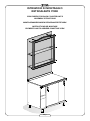
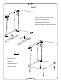
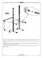
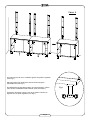
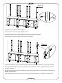
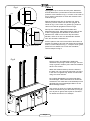
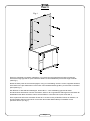
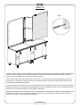
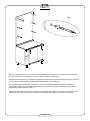
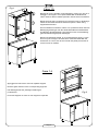
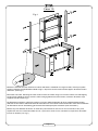
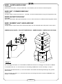
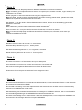
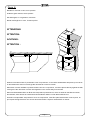
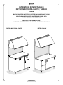
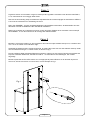
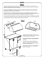
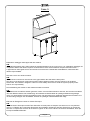
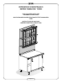
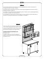
Istruzioni d’uso
Montaggio
Manutenzione
Istructions for Use
Assembly
Maintenance
GUIDA TECNICA
User’s Manual - Technische Anleitung
Guide Technique
Bedienungsanweisung
Montage
Wartung
Utilisation
Assemblage
Entretien
Retrobanchi
YORK
RetroYork180405
Back Counters YORK
Rückentheken YORK
Arrière-comptoirs YORK
ISTRUZIONI DI MONTAGGIO
RETROALZATE YORK
YORK RISERS FOR BACK COUNTER UNITS
ASSEMBLY ISTRUCTIONS
MONTAGEANWEISUNGEN RÜCKENAUFSÄTZEYORK
INSTRUCTIONS DE MONTAGE
ELEMENTS HAUTS ARRIERE-COMPTOIR YORK
Pag.1
Fase 1
Togliere le strisce di scorrimento in legno.
Remove the wood sliding strips.
Die Holzgleitstreifen abnehmen.
Retirer les poutrelles de coulissement en bois.
Fase 2
Montare i piedini.
Apply feet.
Die Füße montieren.
Monter les pieds.
Pag.2
Fase 3
Fissare i montanti alle basi usando le viti in dotazione (M8x14 fondo, autofilettanti 4x25 a legno per piano lavoro).
Attach the vertical uprights to the base unit using the supplied screws (M8x14 bottom, 4x25 self-tapping for wood
worktop).
Die Ständer mit den zur Ausstattung gehörenden Schrauben an den Basiselementen befestigen (M8x14 Boden,
selbstschneidend 4x25 für Holz für Arbeitsfläche).
Fixer les montants sur les bases à l'aide des vis fournies en dotation (M8x14 fond, vis-taraud 4x25 en bois pour
plan de travail)
Pag.3
Fase 4
Accostare le basi al muro e livellarle agendo sui piedini regolabili
(vedi Fig.1)
Place the base units against the wall and level using the
adjustable feet (see Fig.1)
Die Basiselemente der Wand nähern und sie ausrichten, indem
man auf die verstellbaren Füße einwirkt (man sehe Abb.1).
Positionner les bases contre le mur et les mettre à niveau en
agissant sur les pieds réglables (voir Fig.1)
Pag.4
Fig.1
Fase 5
Collegare le basi usando le viti in dotazione.
Connect the base units using the supplied screws.
Die Basiselemente mit den zur Ausstattung gehörenden Schrauben verbinden.
Unir les bases entre elles à l'aide des vis fournies en dotation.
Fase 6
Fissare eventualmente al muro i montanti usando tappi ad espansione (sufficiente n°1 tappo per montante).
Attach the vertical uprights to the wall, if necessary, using expansion screws (1 expansion screw per vertical
upright is sufficient).
Die Ständer eventuell an der Wand befestigen, indem man Spreizverschlüsse verwendet (Nr.1 Verschluss pro
Ständer ist ausreichend)
Fixer éventuellement les montants au mur à l'aide de chevilles à expansion (1 cheville par montant suffit).
Pag.5
Fig.1
Fase 7
6mm
Appoggiare il top in acciaio inox sul piano della base,
facendo attenzione a posizionarlo a 6mm dai montanti
posteriori come indicato in Fig.1, nel caso in cui fosse un
top in granito posizionarlo a 12mm dai montanti come
indicato in Fig.2.
Rest the stainless steel top on the base unit, being
careful to position it 6mm from the rear uprights, as
shown in Fig.1; in the case of a granite top, position it
12mm from vertical uprights as shown in Fig.2.
12mm
Fig.2
Das Top aus rostfreiem Stahl auf die Platte des
Basiselements legen, dabei darauf achten, dass es wie
in Abb.1 angezeigt 6 mm Abstand zu den hinteren
Ständern hat, sollte es sich um ein Top aus Granit
handeln, muss es 12 mm von den Ständern entfernt
sein, wie aus Abb.2 ersichtlich ist.
Poser le plan en acier inox sur la surface de la base, en
laissant une distance de 6 mm par rapport aux montants
arrière, comme indiqué en Fig. 1 ; si le plan est en granit,
placez-le à une distance de 12 mm des montants,
comme indiqué en Fig.2.
Fase 8
Fig.3
Fissare il piano inox dall’interno della base,
utilizzando viti per legno 4x30 vedi Fig.3, nel caso
di top in granito, fissare il piano alle basi mediante
silicone non acetico.
Attach the stainless steel top from the inside of
the base unit, using wood screws 4x30, see Fig.3;
in the case of a granite top, attach it to base unit
using non-acetic silicone.
Die rostfreie Stahlplatte vom Inneren der Basis
aus befestigen, hierbei Schrauben für Holz 4x30
verwenden, man sehe Abb.3, bei Granittops muss
die Platte mit nicht essighaltigem Silikon an der
Basis befestigt werden.
Fixer le plan en acier inox à partir de l'intérieur de
la base, à l'aide de vis pour bois 4x30 (voir Fig.3);
pour le plan en granit, fixer le plan sur les bases
en utilisant du silicone non acétique.
Pag.6
Fase 9
Fig.1
Fissare lo schienale ai montanti, utilizzando n°3+3 viti 3.5x12.5 autoperforanti fornite in dotazione,
inserendole negli appositi fori posti sulla base delle boccole filettate M10 premontate sugli schienali.
(Vedi Fig.1)
Attach the back panel to the vertical uprights, using 3+3 self-drilling 3.5x12.5 screws, supplied standard;
insert them in the pre-drilled holes on the base of the threaded bushings M10, pre-mounted on the back
panel (See Fig.1)
Den Rücken an den Ständern befestigen, hierbei Nr.3 + 3 zur Ausstattung gehörende selbst
durchbohrende Schrauben 3.5x12.5 verwenden, diese in die vorgesehenen Öffnungen auf der Basis der
Gewindebuchsen M10 einsetzen, welche auf den Rücken vormontiert sind (man sehe Abb.1)
Fixer le panneau arrière aux montants à l'aide de 3+3 vis 3.5x12.5 pré-filetées fournies en dotation, en
les introduisant dans les trous situés sur la base des douilles filetées M10 pré-installées sur les
panneaux arrière (voir Fig.1).
Pag.7
Fase 10
Fig.1
Inserire n°3 spine in legno ø8 mm (vedi Fig.1) nel lato dello schienale da accostare a quello già precedentemente
montato, fare accoppiare i due schienaliaccoppiamneto dei due schienali da canalizzare mediante le spine di
legno. Fissare lo schienale ai montanti come visto nella Fase 9.
Insert 3 wood pegs, diam. 8mm (See Fig.1), into the side of the back panel to be butted against the previously
mounted one; couple the two back panels to be channelled using the wood pegs. Attach the back panel to the
vertical uprights as explained in Step 9.
Nr.3 Holzstifte 8 mm (man sehe Abb.1) auf der Seite des Rückens einfügen, die neben die des vorher montierten
Rückens kommen soll, die beiden Verbindungsrücken mit den Holzstiften verbinden, um sie zu kanalisieren. Den
Rücken wie in der Phase 9 gesehen an den Ständern befestigen.
Introduire 3 chevilles en bois ø 8 mm (voir Fig.1) sur l'épaisseur du panneau arrière qui doit être assemblé à celui
précédemment monté, et joindre parfaitement les panneaux entre eux à l'aide des chevilles. Fixer le panneau
arrière aux montants, comme indiqué à la PHASE 9.
Pag.8
Fase 11
Fig.1
Montare i distanziali in ottone avvitando la parte filettata M10 nelle boccole premontate sullo schienale,
interponedo tra loro una rondella in ottone fornita in dotazione (Vedi Fig.1)
Mount the brass spacers by screwing the threaded end M10 into the pre-mounted bushings on the back
panel, placing a brass washer (supplied standard) between them (See Fig.1)
Die Abstandstücke aus Messing montieren, indem das Gewindeteil M10 an die auf dem Rücken
vormontierten Buchsen geschraubt wird, dazwischen eine Messingscheibe positionieren, die mit zur
Ausstattung gehört (man sehe Abb.1).
Monter les entretoises en cuivre en vissant leur partie filetée M10 dans les douilles pré-installées sur le
panneau arrière, en interposant entre elles une rondelle en cuivre fournie en dotation (voir Fig.1).
Pag.9
Fase 12
Fig.2
Fig.1
Inserire la parte terminale filettata del faretto nell’apposito foro già praticato
sullo schienale, con l’accorgimento di inserire nel foro anche i due cavetti
per il cablaggio elettrico (Vedi Fig.1), fissare il faretto utilizzando la rondella
e il dado forniti in dotazione. (Vedi Fig.2)
Insert the threaded end of the spot light into the pre-drilled hole in the back
panel, being careful to also insert the two electrical wires through the hole
(See Fig.1), attach the spot light using the supplied washer and nut (See
Fig.2)
Das Gewinde-Ende des Strahlers in die vorgesehene Öffnung einfügen, mit
der der Rücken schon versehen ist, hierbei darauf achten, dass auch die
beiden kleinen Kabel zur elektrischen Verkabelung in die Öffnung
eingeführt werden (man sehe Abb.1). Den Strahler mittels der Scheibe und
der Mutter befestigen, die zur Ausstattung gehören (man sehe Abb.2).
Introduire l'extrémité filetée du spot dans le trou déjà pratiqué sur le
panneau arrière, en introduisant aussi les deux fils pour le câblage
électrique (voir Fig.1), puis fixer le spot derrière le panneau à l'aide de la
rondelle et de l'écrou fournis en dotation (voir Fig.2).
A questo punto è possibile effettuare il collegamento elettrico alla rete (vedi Fig.1) utilizzando appositi trasformatori
a 12 Volt (non forniti in dotazione).
N.B.
I collegamenti elettrici vanno fatti usufruendo dell’intercapedine che si ha tra il muro e lo schienale.
Il cablaggio dei componenti elettrici del relativo impianto di illuminazione deve essere effettuato da personale
autorizzato.L’applicazione delle vigenti norme di sicurezza e messa a terra è demandato all’installatore,
unitamente alle relative responsabilità.
Now, the spot light can be connected to the mains (see Fig.1) using special 12 volt transformers (not supplied).
N.B.
The electrical connections must be set in the gap between the wall and the back panel.
The wiring of the electrical components and the relative lighting system must be carried out by qualified
technicians.The installer is obliged to observe current safety norms and to earth the system properly under his/her
own responsibility.
Nunmehr kann der elektrische Anschluss an das Netz vorgenommen werden (man sehe Abb.1), wobei eigens
vorgesehene 12 Volt Trafos eingesetzt werden (diese werden nicht mit der Ausstattung geliefert).
N.B.
Die elektrischen Anschlüsse werden gemacht, indem man den Zwischenraum ausnutzt, der zwischen der Wand
und dem Rücken besteht. Die Verkabelung der elektrischen Bestandteile der jeweiligen Beleuchtungsanlage
muss von autorisiertem Personal ausgeführt werden. Die Anwendung der geltenden Sicherheitsvorschriften und
die Vererdung obliegen dem Installateur, welcher die jeweiligen Verantwortlichkeiten trägt.
Il est possible alors d'effectuer le branchement électrique au réseau (voir Fig.1) au moyen de transformateurs à
12 Volts (non fournis en dotation).
N.B.
Les connexions électriques doivent être effectuées en tirant partie de l'espace vide entre le mur et le panneau
arrière. Le câblage des composants électriques de l'installation d'éclairage doit être effectué par un technicien
autorisé. Le respect des normes de sécurité en vigueur et de la mise à la terre incombe à l'installateur, ainsi que
les responsabilités afférentes.
Pag.10
Fig.1
Fase 13
Montare la cornice frontale, posizionandola in modo che i fori per il
fissaggio si accoppino con la parte filettata M4 dei distanziali in
ottone, fissare il tutto mediante pomelli in ottone forniti in dotazione.
Mount the front frame, positioning it so that the holes for fastening it
match the threaded end M4 of the brass spacers, attach using
supplied brass knobs.
Den Frontrahmen montieren, indem er so positioniert wird, dass die
Befestigungsöffnungen mit den Gewindeteil M4 der Distanzstücke
aus Messing übereinstimmen. Das Ganze mit den zur Ausstattung
gehörenden Messingknöpfen befestigen.
Monter l'encadrement frontal, en le positionnant de façon à ce que
les trous pour le fixage coïncident avec l'extrémité filetée M4 des
entretoises en cuivre; fixer le tout à l'aide des petits pommeaux en
cuivre fournis en dotation.
Fase 14
Appoggiare le mensole in vetro sui rispettivi supporti.
Rest the glass shelves on the corresponding supports.
Die Glasregale auf den jeweiligen Halterungen
positionieren.
Fig.2
Poser les étagères en verre sur leur supports respectifs.
Pag.11
Fase 15
Fig.1
Montare le fiancate terminali, fissando le inferiori dall’interno mediante viti a legno 4.5x30, mentre per quelle
superiori utilizzare viti autofilettanti 6.8x40 a legno, dopo aver serrato il tutto inserire tappini decorativi forniti in
dotazione. (Vedi Fig.1)
Mount the end sides, attaching the lower sections from the inside using wood screws 4.5x30; use self-tapping
wood screws 6.8x40 for the top sections, after having tightened all of the screws, insert the decorative caps
supplied standard (See Fig.1)
Die Endseiten montieren, indem die unteren von Innen mittels Schrauben für Holz 4.5x30 befestigt werden,
während für die oberen selbstschneidende Schrauben für Holz 6.8x40 verwendet werden. Nach dem Festziehen
der Schrauben die zur Ausstattung gehörenden Dekorationspfropfen aufsetzen (man sehe Abb.1).
Monter les joues latérales de finition en fixant les joues inférieures avec les vis en bois 4.5x30, et les joues
supérieures avec les vis-taraud 6.8x40 en bois ; après avoir serrer le tout, introduire les capuchons décoratifs
fournis en dotation (voir Fig.1)
Pag.12
ISTRUZIONI DI MONTAGGIO
RETROBANCHI AD ANGOLO
BASE PIU’ALZATA
ASSEMBLY INSTRUCTIONS FOR BACK COUNTER CORNERS,
BASE WITH RISER
MONTAGEANWEISUNGEN FÜR ECKIGE RÜCKENTHEKEN,
BASISELEMENT MIT AUFSATZ
INSTRUCTIONS DE MONTAGE POUR ARRIERE-COMPTOIRS
ANGULAIRES,
BASE AVEC ELEMENT HAUT
Pag.13
ATTENZIONE:
In una composizione di retrobanchi, gli elementi ad angolo vanno sempre posizionati prima dei lineari, avendo
cura di inserirli esattamente in corrispondenza dell’angolo, lasciando tra la base e la parete la misura indicata a
disegno.
ATTENTION:
In a composition of back counter units, the corner units must always be positioned before the linear units, being
careful to insert them in exact correspondence to the corner, leaving the distance indicated in the drawing
between the base unit and the wall.
ACHTUNG:
Bei einer Rückenthekenkomposition müssen die eckigen Elemente immer vor den geraden Elementen
positioniert werden, dabei darauf achten, dass sie genau in Übereinstimmung mit der Ecke eingefügt werden,
wobei zwischen der Basis und der Wand der in der Zeichnung angegebene Abstand bestehen muss.
ATTENTION :
Dans une composition d'arrière-comptoirs, les modules angulaires doivent toujours être positionnés avant les
modules linéaires, en faisant attention de les placer exactement en correspondance de l'angle, et en laissant
entre la base et la paroi l'espace indiqué dans le schéma.
DIMENSIONI IN PIANTA: / PROJECT DIMENSIONS: / ABMESSUNGEN: / DIMENSIONS SUR PLAN :
30 mm
400/630 mm
BASE - ALZATA A45°:
400/630 mm
BASE - ALZATA A90°:
Per le istruzioni di montaggio seguire da
FASE1 a FASE6 le istruzioni di montaggio dei
Retrobanchi LINEARI.
For assembly instructions, follow the
instructions for assembling the LINEAR back
counter units from Step 1 to Step 6.
400/630 mm
Hinsichtlich der Montage die PHASEN 1 bis 6
der Montageanleitungen der GERADEN
Rückentheken befolgen.
Pour le montage, suivre les instructions de
montage des arrière-comptoirs LINEAIRES,
de la PHASE 1 à la PHASE 6.
BASE - ALZATA B45°:
Pag.14
BASE - ALZATA ANGOLO B90°
ATTENZIONE;
Questo tipo di retrobanco, base più alzata B90°, va assemblato prima di essere accostato alla parete.
BASE UNIT CORNER RISER B90°
ATTENTION;
This type of back counter unit, base unit + riser B90°, must be assembled before being moved against the wall.
BASIS-AUFSATZ ECKE B90°
ACHTUNG:
Diese Art Rückentheke, Basis plus Aufsatz B90°, muss vor dem Anrücken an die Wand zusammengebaut werden.
BASE ELEMENT HAUT ANGULAIRE B90°
ATTENTION :
Ce type d'arrière-comptoir (base avec élément haut B90°) doit être assemblé avant d'être placé contre la paroi.
DIMENSIONI IN PIANTA: / PROJECT DIMENSIONS: / ABMESSUNGEN: / DIMENSIONS SUR PLAN :
C
30 mm
30 mm
D
400/630 mm
B
A
Fase 1
Per il montaggio della base “A” vedi da FASE1 a FASE3 delle istruzioni di montaggio dei retrobanchi LINEARI.
To assemble base unit “A”, see instructions for assembling LINEAR back counter units Step 1 to Step 3
Zur Montage des Basiselements „A“ sehe man PHASE 1 bis PHASE 3 der Montageanleitungen der geraden
Rückentheken.
Pour le montage de la base « A », suivre les instructions de montage des arrière-comptoirs LINEAIRES, de la
PHASE 1 à la PHASE 3.
Pag.15
Fase 2
Fissare il montante “B” alla parte posteriore della base utilizzando le viti fornite in dotazione.
N.B: Il montante è già completo di elemento estetico di copertura (Inox, lamiera verniciata, legno massello) che
caratterizza i vari modelli.
Attach upright “B” to the back of the base unit using the supplied screws.
N.B.: the vertical upright is already supplied with the decorative covering (stainless steel, painted sheet metal,
solid wood trim) which characterises the various models.
Den Ständer „B“ an dem hinteren Teil des Basiselements montieren, hierzu die zur Ausstattung gehörenden
Schrauben verwenden.
N.B.: Der Ständer ist schon komplett mit dem ästhetischem Abdeckungselement (rostfreier Stahl, lackiertes
Blech, Massivholz), welches die verschiedenen Modelle charakterisiert.
Fixer le montant « B » sur la partie arrière de la base à l'aide des vis fournies en dotation.
N.B.: Le montant est déjà équipé de l'élément décoratif de revêtement (inox, tôle peinte, bois massif) qui
caractérise les différents modèles.
Fase 3
Montare l’elemento cielino di raccordo “C” dove previsto.
Assemble the top element of joint “C”, where present.
Das Deckenverbindungselement “C“, wo vorgesehen, montieren.
Monter l'élément plafonnier de raccord “C” à l'endroit prévu.
Fase 4
Accostare il retrobanco così assemblato, allo spigolo della parete.
Once assembled, move the back counter unit against the corner of the wall.
Die somit zusammengebaute Rückentheke an die Ecke der Wand rücken.
Positionner l'arrière-comptoir ainsi assemblé contre l'angle de la paroi.
Fase 5
Procedere alla canalizzazione con eventuali basi e alzate adiacenti, come indicato nelle FASI 4 e 5 delle istruzioni
di montaggio dei retrobanchi LINEARI.
Proceed with channelling to any other adjacent bases and risers, as shown in STEPS 4 and 5 of the assembly
instructions for LINEAR back counter units.
Die Kanalisierung mit eventuellen Basiselementen und anliegenden Aufsätzen ausführen, wie es in der PHASE 4
und 5 der Montageanleitungen der GERADEN Rückentheken beschrieben ist.
Procéder à l'assemblage avec les autres bases et éléments hauts adjacents, comme indiqué aux PHASES 4 et 5
des instructions de montage des arrière-comptoirs LINEAIRES.
Pag.16
Fase 6
Montare le mensole in vetro, dove previsto.
Install the glass shelves, where present.
Die Glasregale, wo vorgesehen, montieren.
Monter les étagères en verre, à l'endroit prévu.
ATTENZIONE:
C
ATTENTION:
ACHTUNG:
D
ATTENTION :
B
A
Quando il retrobanco B90° è posizionato a fine composizione, va accostato direttamente alla parete, provocando
un allontanamento dal muro di tutti gli altri retrobanchi ad esso accostati.
When back counter unit B90° is positioned at the end of a composition, it must be placed directly against the wall,
moving all of the other back counter units against it to be moved away from the wall.
Wenn die Rückentheke B90° am Ende der Komposition positioniert ist, muss sie direkt an die Wand kommen,
dies bewirkt, dass alle mit ihr kombinierten Rückentheken weiter von der Wand entfernt sind.
Si l'arrière-comptoir B90° est positionné en fin de composition, il doit être placé directement contre la paroi, en
provoquant l'éloignement du mur de tous les autres arrière-comptoirs assemblés à ce dernier.
Pag.17
ISTRUZIONI DI MONTAGGIO
RETRO MACCHINA CAFFE’/ SNACK
YORK
BACK COUNTER UNITS FOR COFFEE MACHINE/SNACK YORK
MONTAGEANWEISUNGEN KAFFEEMASCHINE- UND
SNACK-RÜCKENAUFSÄTZE YORK
INSTRUCTIONS DE MONTAGE
ARRIERE-COMPTOIR POUR MACHINE A CAFE / SNACK YORK
RETRO MACCHINA CAFFE’
RETRO SNACK
Pag.18
Fase 1
Togliere le strisce di scorrimento in legno,montare piedini regolabili e montanti come descritto nelle FASI 1,
2 e 3, nelle istruzioni di montaggio delle alzate.
Remove the wood sliding strips, assemble the adjustable feet and vertical uprights as described in STEPS 1,
2 and 3 in the instructions for assembling the risers.
Wie in den PHASEN 1, 2 und 3 der Montageanleitung der Aufsätze beschrieben, die Gleitstreifen aus Holz
abnehmen und die verstellbaren Füße und Ständer installieren.
Retirer les poutrelles de coulissement en bois, monter les pieds réglables et les montants comme indiqué
aux PHASES 1, 2 et 3 des instructions de montage des éléments hauts.
Fase 2
Montare lo schienale rivestito inox, appoggiando il lato inferiore sopra l’alzatina del top inox, e fissare il tutto
con n° 3+3 viti 4.2x16 come indicato in Fig.1.
Assemble the stainless steel covered back panel, by resting the lower side over the stainless steel top small
riser and attach all using 3+3 4.2x16 screws, as shown in Fig.1.
Die mit rostfreiem Stahl verkleidete Rückseite montieren, indem man den unteren Teil über den Aufsatz des
Tops aus rostfreiem Stahl lehnt, das Ganze mit Nr. 3 + 3 Schrauben 4.2x16 befestigen, wie in Abb.1
angezeigt.
Monter le panneau arrière revêtu d'acier inox, en appuyant la partie inférieure sur le dosseret du plan en
acier inox, et fixer le tout avec 3+3 vis 4.2x16, comme indiqué en Fig.1.
Fig.1
Pag.19
Fase 3
Canalizzare il retro Macchina caffè o Snack con le altre basi della composizione come descritto nelle
istruzioni di montaggio delle alzate nella FASE 5, con l’accorgimento di fare accoppiare anche gli schienali
mediante l’utilizzo di spine in legno ø8 (vedi Fig.3).
Channel the Coffee Machine or Snack back counter unit with the other base units of the composition as
described in the instructions for assembling the risers in STEP 5, being careful to also match the back
panels using the wood pegs, diam. 8 (see Fig.3).
Das Kaffeemaschinen oder Snack-Rückenelement mit den anderen Basiselementen der Komposition
kanalisieren, wie es in den Montageanleitungen der Aufsätze in der PHASE 5 beschrieben ist, darauf achten,
dass auch die Rückseiten mit Hilf von Holzstiften ø8 verbunden werden (man sehe Abb.3).
Unir l'arrière-comptoir pour Machine à café ou Snack avec les autres bases de la composition en procédant
comme indiqué à la PHASE 5 des instructions de montage des éléments hauts, en accouplant parfaitement
les panneaux arrière entre eux à l'aide des chevilles en bois ø8 (voir Fig.3).
Fase 4
Fig.2
Fig.1
B
A
Agganciare la cappa all’apposito supporto “A”,
premontato sullo schienale (vedi Fig.1), mediante
il profilo posteriore “B” (vedi Fig.2)
Hook the hood to support “A”, pre-assembled on
the back panel (see Fig.1), using rear profile “B”
(see Fig.2)
Die Haube in die vorgesehene Halterung “A“,
welche auf der Rückseite vormontiert ist (man
sehe Abb.1) einhaken, dies mittels des hinteren
Profils “B“ (man sehe Abb.2).
Fixer la hotte sur le support “A” pré-installé sur le
panneau arrière (voir Fig.1), à l'aide du profil
arrière “B” (voir Fig.2)
Fig.3
Pag.20
Fase 5
Effettuare il cablaggio della cappa alla rete elettrica.
N.B.
I collegamenti elettrici vanno fatti usufruendo dell’intercapedine che si ha tra il muro e lo schienale.Il cablaggio dei
componenti elettrici del relativo impianto di illuminazione deve essere effettuato da personale autorizzato.
L’applicazione delle vigenti norme di sicurezza e messa a terra è demandato all’installatore, unitamente alle
relative responsabilità.
Wire the hood to the electrical mains.
N.B.
The electrical connections must be set in the gap between the wall and the back panel.
The wiring of the electrical components and the relative lighting system must be carried out by qualified
technicians. The installer is obliged to observe current safety norms and to earth the system properly under
his/her own responsibility.
Die Verkabelung der Haube an das elektrische Netz vornehmen.
N.B.
Die elektrischen Anschlüsse werden gemacht, indem man den Zwischenraum ausnutzt, der zwischen der Wand
und dem Rücken besteht. Die Verkabelung der elektrischen Bestandteile der jeweiligen Beleuchtungsanlage
muss von autorisiertem Personal ausgeführt werden. Die Anwendung der geltenden Sicherheitsvorschriften und
die Vererdung obliegen dem Installateur, welcher die jeweiligen Verantwortlichkeiten trägt.
Effectuer le câblage de la hotte au réseau électrique.
N.B.
Les connexions électriques doivent être effectuées en tirant partie de l'espace vide entre le mur et le panneau
arrière. Le câblage des composants électriques de l'installation d'éclairage doit être effectué par un technicien
autorisé. Le respect des normes de sécurité en vigueur et de la mise à la terre incombe à l'installateur, ainsi que
les responsabilités afférentes.
Pag.21
Fase 6
Montare fianchi terminali su base e alzata, come descritto nella FASE 15 delle istruzioni di montaggio delle alzate.
Assemble the end sides to the base units and risers, as described in Step 15 of the riser assembly instructions.
Die Abschlussseiten auf dem Basiselement und dem Aufsatz montieren, wie es in PHASE 15 der
Montageanleitungen der Aufsätze beschrieben ist.
Monter les joues latérales de finitions sur la base et sur l'élément haut, comme indiqué à la PHASE 15 des
instructions de montage des éléments hauts.
Pag.22
ISTRUZIONI DI MONTAGGIO
RETRO TABACCHI YORK
BACK COUNTER UNITS YORK
ASSEMBLY ISTRUCTIONS
MONTAGEANWEISUNGEN RÜCKENAUFSÄTZE TABAKWAREN
YORK
INSTRUCTIONS DE MONTAGE
ARRIERE-COMPTOIR A TABAC YORK
Pag.23
Fase 1
Per l’installazione della base retro Tabacchi, procedere esattamente come indicato nelle istruzioni di
montaggio delle alzate, da FASE 1 a FASE 15.
To install the Tobacco product back counter unit, proceed exactly as indicated in the instructions for riser
assembly from STEP 1 to STEP 15.
Zur Installation des Rückenbasiselements Tabakwaren genauso vorgehen, wie es in der Montageanleitung
der Aufsätze von PHASE 1 bis 15 beschrieben ist.
Pour l'installation de la base de l'arrière-comptoir à tabac, procéder exactement comme indiqué dans les
instructions de montage des éléments hauts, de la PHASE 1 à la PHASE 15.
Fase 2
Inserire i due box in vetro per tabacchi all’interno della
cornice frontale, appoggiandoli sulle mensole in vetro.
Insert the two glass boxes for tobacco products inside
the front frame, resting them on the glass shelves.
Die beiden Glasboxen für Tabakwaren in den
Frontrahmen einsetzen und sie dabei auf die
Glasregale stützen.
Introduire les deux box en verre pour cigarettes à
l'intérieur de l'encadrement frontal, en les appuyant sur
les étagères en verre.
Pag.24
Società Industria Frigoriferi e Arredamenti
61022 Colbordolo, 15/19
Tel. 0721.4741 - Fax 0721.497507
E-mail: [email protected]
Sito Internet: http:// www.sifaspa.it


![32.393 [WT] Fogger manual 6Tnew](http://vs1.manualzilla.com/store/data/006164516_1-6119f057c045d3e31d2ffb4326e242f0-150x150.png)