1
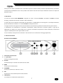
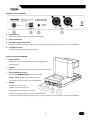
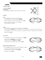
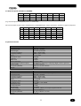
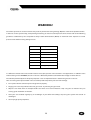
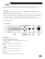
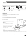
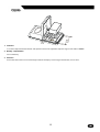
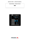
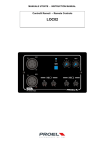
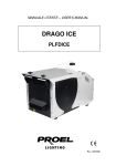
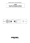
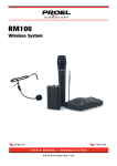
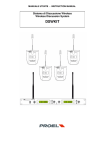
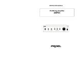
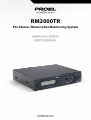
RM2000TR
PLL Stereo / Mono In Ear Monitoring System
Indice / Index
1. Precauzioni D’uso .......................................................................................................................................................... 3
2. Descrizione ................................................................................................................................................................... 7
3. Funzioni e Controlli ....................................................................................................................................................... 7
Pannello Frontale RM2000 ............................................................................................................................................ 7
Ricevitore Bodypack RM2000R ...................................................................................................................................... 8
4. Operazioni di Base ....................................................................................................................................................... 10
Trasmettitore RM2000 ................................................................................................................................................ 10
POWER ON/OFF ................................................................................................................................................................10
Settaggio ................................................................................................................................................................... 10
Stato ..................................................................................................................................................................................10
Canale ...............................................................................................................................................................................10
Stereo / Mono ...................................................................................................................................................................10
Regolazione del segnale RF in uscita ...............................................................................................................................10
5.Tabella Frequenze (702.000-731.000MHZ) .................................................................................................................... 11
6.Specifiche Tecniche...................................................................................................................................................... 11
1. Safety Instructions ....................................................................................................................................................... 13
2. Description ................................................................................................................................................................. 17
3. Functions and Controls ................................................................................................................................................ 17
Front Panel RM2000 ................................................................................................................................................... 17
Rear Panel RM2000 ..................................................................................................................................................... 18
Body Pack Receiver RM2000R ...................................................................................................................................... 18
4. Operation ................................................................................................................................................................... 20
Transmitter RM2000 .................................................................................................................................................. 20
Power on / off ...................................................................................................................................................................20
Setting ....................................................................................................................................................................... 20
Status ................................................................................................................................................................................20
Channel.............................................................................................................................................................................20
Stereo/Mono.....................................................................................................................................................................20
Adjustment of the RF output signal.................................................................................................................................20
5. Frequency Table (702.000 - 731.000 MHZ) .................................................................................................................... 21
6. Technical Specifications ............................................................................................................................................... 21
2
1. Precauzioni D’uso
AVVERTENZA: Per ridurre il rischio di folgorazione, non rimuovere il coperchio (o il pannello posteriore). All’interno non sono contenute parti riparabili
dall’utente; affidare la riparazione a personale qualificato.
ATTENZIONE: Per ridurre il rischio d’incendio o di folgorazione, non esporre questo apparecchio alla pioggia o all’umidità.
Questo simbolo, ove compare, segnala la presenza di un voltaggio pericoloso non isolato all’interno del corpo dell’apparecchio,
voltaggio sufficiente a costituire un rischio di folgorazione.
Questo simbolo, ove appare, segnala importanti istruzioni d’uso e manutenzione nel testo allegato. Leggere il manuale
RACCOMANDAZIONI
Tutte le istruzioni di sicurezza e funzionamento devono essere lette prima di mettere in funzione l’apparecchio.
Conservare le istruzioni
Le istruzioni di sicurezza e di funzionamento devono essere conservate per un futuro riferimento.
Il presente manuale è parte integrante del prodotto e lo deve accompagnare in caso di eventuali cambi di proprietà. In questo modo il nuovo proprietario
potrà conoscere le istruzioni relative a installazione, funzionamento e sicurezza.
Prestare attenzione
Tutte le avvertenze sull’apparecchio e nelle istruzioni di funzionamento devono essere seguite fedelmente. Osservare tutti gli avvertimenti.
Seguire le istruzioni
Tutte le istruzioni per il funzionamento e per l’utente devono essere seguite.
Le note precedute dal simbolo
contengono importanti informazioni sulla sicurezza: leggerle con particolare attenzione.
ISTRUZIONI DI SICUREZZA IN DETTAGLIO.
Acqua ed umidità
L’apparecchio non deve essere utilizzato in prossimità di acqua (per es. vicino a vasche da bagno, lavelli da cucina, in prossimità di piscine ecc.).
Calore
L’apparecchio deve essere posto lontano da fonti di calore come radiatori, termostati, asciuga biancheria, o altri apparecchi che producono calore.
Alimentazione
• L’apparecchio deve essere collegato soltanto al tipo di alimentazione descritto nelle istruzioni d’uso o segnalato sull’apparecchio.
• Se la spina in dotazione non combacia con la presa, rivolgersi ad un elettricista per farsi installare una presa appropriata.
Messa a terra o polarizzazione
• Si devono prendere precauzioni in modo tale che la messa a terra e la polarizzazione dell’apparecchio non siano pregiudicate.
• Le parti metalliche dell’apparecchiatura sono collegate a massa tramite il cavo d’alimentazione.
• Se la presa utilizzata per alimentazione non possiede collegamento a massa, rivolgersi ad un elettricista qualificato per fare collegare l’apparato a massa
tramite il terminale.
3
Protezione del cavo di alimentazione
Il cavo di alimentazione elettrica deve essere installato in modo che non venga calpestato o danneggiato da oggetti posti sopra o contro, prestando
particolare attenzione a cavi e spine, prese a muro.
Pulizia
• Quando l’unità deve essere pulita, è possibile eliminare la polvere utilizzando un getto d’aria compressa o un panno inumidito.
• Non pulire l’unità utilizzando solventi quali trielina, diluenti per vernici, alcol, fluidi ad alta volatilità o altri liquidi infiammabili.
Periodi di non utilizzo
Il cavo di alimentazione dell’apparecchio deve essere staccato dalla presa se rimane inutilizzato per un lungo periodo.
Ingresso di liquidi o oggetti
Si deve prestare attenzione che non cadano oggetti e non si versino liquidi nel corpo dell’apparecchio.
Uso sicuro della linea d’alimentazione
• Quando si scollega l’apparato alla rete tenere saldamente sia la spina che la presa.
• Quando l’unità non viene utilizzata per un periodo prolungato, interrompere l’alimentazione estraendo la spina dalla presa dell’alimentazione
• Per evitare danni alla linea d’alimentazione dell’apparato, non mettere in trazione il cavo d’alimentazione e non utilizzare un cavo attorcigliato.
• Per evitare il danneggiamento del cavo d’alimentazione dell’apparato, assicurarsi che questo non venga calpestato o schiacciato da oggetti pesanti.
Spostamento dell’unità
Prima di ogni spostamento, verificare che l’unità sia spenta. Il cavo d’alimentazione deve essere estratto dalla presa, così come i collegamenti dell’unità con
altre linee.
Non smontare l’unità
Non tentare di smontare né riparare da soli l’unità. Per qualsiasi problema non risolvibile con l’aiuto del presente manuale, rivolgersi a un tecnico qualificato
o consultare la nostra compagnia. Qualsiasi uso non appropriato può causare incendi o scosse elettriche.
Malfunzionamenti
• Non tentare mai di eseguire riparazioni diverse da quelle descritte nel presente manuale.
• Contattare un centro di servizio autorizzato o del personale altamente qualificato nei seguenti casi:
- Quando l’apparato non funziona o funziona in modo anomalo.
- Se il cavo d’alimentazione o la spina sono danneggiati.
- Sono penetrati oggetti estranei o è stato versato del liquido nell’apparecchio.
- L’apparecchio è stato esposto alla pioggia.
- L’apparecchio non sembra funzionare normalmente o presenta un evidente cambiamento nelle prestazioni.
- L’apparecchio è caduto, o il corpo è danneggiato.
Manutenzione
L’utente non deve tentare di riparare l’apparecchio oltre a quanto è descritto nelle istruzioni di funzionamento. Ogni altra riparazione deve essere affidata a
personale specializzato.
4
IMPORTANTI NORME DI SICUREZZA
•
Installare seguendo le istruzioni.
•
Il voltaggio d’alimentazione dell’unità è abbastanza elevato per evitare il rischio di scosse elettriche, non installare, collegare o sconnettere
l’alimentazione quando l’apparato è acceso.
•
Non aprire mai l’apparecchiatura: all’interno non esistono parti utilizzabili dall’utente.
•
Se si avverte uno strano odore proveniente dall’apparato, spegnerlo immediatamente e sconnettere il cavo dell’alimentazione.
•
Non ostruire le griglie di ventilazione dell’apparato.
•
Evitare che l’unità lavori in sovraccarico per tempo prolungato.
•
Non forzare i comandi (pulsanti, controlli, ecc.)
•
Per ragioni di sicurezza, non annullare il collegamento a massa della spina. Il collegamento a massa è necessario per salvaguardare la
sicurezza dell’operatore
•
Utilizzare unicamente i connettori e gi accessori specificati dal produttore.
•
In presenza di temporali con fulmini o quando l’apparato non è utilizzato, estrarre la spina d’alimentazione dalla presa.
•
Per prevenire il rischio di incendi e scosse elettriche, è necessario tenere l’apparato lontano da spruzzi e gocce. Sopra l’apparato non
devono essere collocati vasi o altri oggetti contenenti liquidi. In caso si verifichino interferenze nel circuito di provenienza, il valore di THD sarà
superiore al 10%. Non installare questo apparato in una libreria o in altri luoghi a spazio ristretto
•
PROEL S.P.A. declina ogni responsabilità in caso di scorretta installazione dell’unità.
L’utilizzo di questo apparecchio può richiedere in certe aree una licenza ministeriale in quanto può essere in grado
di funzionare a frequenze non autorizzate. Si suggerisce di rivolgersi alle autorità competenti per ottenere le
informazioni relative all’utilizzo di apparecchiature radio nella propria regione.
5
Avvertenza
Attenzione l’utilizzo scorretto di questo sistema può causare lesioni permanenti all’apparato uditivo se usato a volume
eccessivo , si raccomanda di usare il più basso volume possibile .
Si consiglia di attenersi alle seguenti direttive stabilite dalla OSHA ( Occupational Safety Health Administration) sul massimo
tempo si esposizione a vari livelli di pressione sonora per evitare di causare lesioni all’apparato uditivo:
spl
Max esposizione
90dB
8 ore
95dB
4 ore
100dB
2 ore
105dB
1 ora
110dB
½ ora
115dB
15 minuti
120dB e oltre
Danni irreversibili
Misurare esattamente la pressione sonora (SPL ) sul timpano nelle produzioni musicali è estremamente difficoltoso.
Oltre alla pressione sonora corrispondente al volume generato dagli auricolari del RM2000R, il valore SPL al livello
dell’orecchio dipende dal volume generato nell’ambiente da altoparlanti ed altri strumenti. Altro fattore importante è
dovuto al grado di isolamento degli auricolari usati e dalla loro qualità.
Per la protezione dell’apparato uditivo durante l’utilizzo di questo apparecchio si raccomanda:
• Aumentare il volume quanto basta ad un ascolto adeguato.
• Un ronzio nelle orecchie può indicare un guadagno eccessivamente elevato.
• Prima e dopo l’uso, avere cura di disinfettare gli auricolari per prevenire eventuali infezioni. Evitare di usare gli auricolari in
caso di infezioni e/o eccessivi fastidi.
• Eseguire un esame audiometrico con regolarità.
6
Grazie per aver scelto un prodotto Proel e della fiducia riposta nel nostro marchio, sinonimo di professionalità, accuratezza,
elevata qualità ed affidabilità. Tutti i nostri prodotti sono conformi alle normative CE per utilizzazione continua in impianti di
diffusione sonora.
2. Descrizione
Il sistema ear monitor PROEL RM2000TR è composto da 3 parti : ricevitore RM2000R, trasmettitore RM2000 e auricolari
Kossplug , riponibili nella comoda custodia in ABS in dotazione.
Il sistema opera su 16 frequenze selezionabili nella banda 702 ÷ 731MHz (UHF) con tecnologia PLL e contemporaneamente,
possono funzionare al massimo n° 9 sistemi RM2000TR su frequenze diverse .
La migliore ricezione del segnale emesso dal trasmettitore è costantemente garantita dal sistema Diversity del ricevitore.
Il trasmettitore ha caratteristiche e prestazioni notevolmente evolute, fornendo la massima qualità in ogni tipo di
applicazione. E’ dotato di un ampio display LCD in grado di visualizzare la frequenza di lavoro selezionata, l’intensità del
segnale in radiofrequenza e del segnale audio in uscita.
Il case in metallo, inoltre, può essere montato in rack standard da 19” tramite kit di montaggio (opzionale).
3. Funzioni e Controlli
Pannello Frontale RM2000
1. Interruttore d’accensione
2. ¼ “ jack stereo
Uscita per collegamento cuffia.
3. Volume
Potenziometro per il controllo del volume d’uscita cuffia.
4. MEM
Pulsante per memorizzazione.
5. UP/DOWN
Pulsanti per aumentare o diminuire i valori.
6. SET
Pulsante per la scelta della frequenza e delle funzioni.
7. LCD Display
Schermo per la visualizzazione delle funzioni.
7
Pannello posteriore RM2000
1. Ingresso Audio
Connettore combo per ingresso segnale LEFT e RIGHT.
2. Uscita audio stereo
3. Connettore alimentazione VDC
Collegare a questo connettore l’alimentatore AC/DC precedentemente collegato alla presa di rete 220-230VAC.
4. Connettore antenna
Connettore tipo TNC per inserimento antenna.
Ricevitore Bodypack RM2000R
1. Ingresso Cuffia
Connettore 3,5 mm stereo jack femmina per il collegamento
degli auricolari.
2. Volume
Potenziometro per il controllo del volume d’uscita degli auricolari.
3.
Interruttore Di Accensione
L’interruttore POWER OFF ON possiede 3 posizioni:
spento - stereo - mono. L’accensione della spia
per un istante indica lo stato di carica della batteria.
4.
Bat.LED
LED bi-colore rosso / verde.
Il colore verde indica il corretto
4
3
funzionamento e la ricezione del segnale,
il colore rosso segnala lo stato di carica della batteria da 9V.
2
1
La mancata accensione della spia segnala che il ricevitore è posto su di una frequenza diversa dal trasmettitore.
8
6
5
7
1. Selettori
Selezione del canale di ricezione 1-16 e del circuito squelch (range dello squelch compreso tra -80 e -100 dBm).
2. Vano Batterie
Vano per l’alloggiamento della batteria da 9V.
3. Antenna
La copertura dell’antenna (ad esempio con le mani) comporta un’attenuazione del segnale, con possibili fruscii o perdite
di trasmissione.
9
4. Operazioni di Base
Trasmettitore RM2000
POWER ON/OFF
• Premete il pulsante POWER per mettere in funzione il trasmettitore.
Settaggio
Stato
• Premendo SET una volta, sullo schermo LCD lampeggia
lo stato del trasmettitore. Premendo i pulsanti UP/DOWN
può essere attivata la trasmissione (sul display appare la scritta ON)
L
R
Channel
712.455
Mhz
oppure il trasmettitore può essere messo in STANDBY
(sul display apparirà la scritta OF).
Canale
• Premendo SET due volte, sullo schermo LCD lampeggia la scritta Channel.
Premendo i pulsanti UP/DOWN può essere selezionato il canale di trasmissione: sul display viene visualizzato sopra la
scritta CHANNEL il numero del canale selezionato con la rispettiva frequenza. Per memorizzare la scelta effettuata
premere il pulsante MEM.
Stereo / Mono
• Premendo SET tre volte sullo schermo LCD lampeggia la scritta MONO.
Premendo i pulsanti UP/DOWN può essere selezionata
L
R
la modalità di trasmissione STEREO oppure MONO.
Channel
712.455 Mhz
Per memorizzare la scelta effettuata premere il pulsante MEM.
Regolazione del segnale RF in uscita
• Premendo SET quattro volte, sullo schermo LCD lampeggia la scritta RF
con accanto il valore corrente: 0 = 10mw; 1 = 50mw.
L
R
Selezionare il livello desiderato con i tasti UP/DOWN
Channel
e confermare con il tasto MEM.
10
712.455 Mhz
5.Tabella Frequenze (702.000-731.000MHZ)
CH 1
CH 2
CH 3
CH 4
CH 5
CH 6
CH 7
CH 8
702.125 702.875 703.775 705.875 724.875 730.125 702.500 703.250
CH 9
CH 10
CH 11
CH 12
CH 13
CH 14
CH 15
CH 16
704.150 706.250 725.250 730.500 714.725 714.925 725.475 730.725
(In grassetto frequenze compatibili per uso in simultanea).
Nel caso di utilizzo con più sistemi radiomicrofonici serie RMW8/10, per evitare interferenze, utilizzare le seguenti frequenze:
CH 1
CH 2
CH 4
CH 5
CH 6
CH 8
Group1 Group2 Group3 Group5 Group7 Group8 Group12
798.925
800.725
805.725
816.325 819.525
825.725
-
6.Specifiche Tecniche
MODEL
Channel
Frequency band:
Receiver type:
Frequency response:
Frequency stability:
T.H.D:
Modulation mode
S/N Ratio
Mute Level
Stereo Separation
Load Impedance (phone output)
Power Supply
Dimensions (WxDxH)
Weight
RM2000R
Multi-channels, up 16 frequency preset
UHF 798 ÷ 827MHz
PLL UHF Synthesized
80Hz - 13KHz (-3dB)
0,005% (-10°C - 50°C)
< 1,3% 1KHZ
FM (F3E)
> 90dB
2-24 µV
>45dB (q 1 Khz )
>16 Ohm 3,5 stereo ( tip = left, Ring= Right , Sleeve = ground )
9V Alkaline battery
210 mm x 156 mm x 44 mm
0,08 Kg
MODEL
Trasmission mode
Frequency band:
Frequency response:
Frequency stability:
T.H.D:
Modulation mode
RF Output power
Modulation Limit
Harmonic Radiate
Max deviaton
Power Supply
Microphone type
Dimensions (WxDxH)
Weight
RM2000
PLL Multi-channels, 16 frequency preset
UHF 798 ÷ 827MHz
80Hz - 13KHz (-3dB)
0,005% (-10°C - 50°C)
< 1 % 1KHZ
FM (F3E)
Low 10mw , High 50mW
± 40Khz
< 4 nW
+/-35KHz
12 volt DC 500 mA, AC adapter supplied 230 volt
Hcm38 ( optional )
66 mm. x 103 mm. x 23 mm
1,118 Kg -
11
Raccomandazioni
•
•
•
•
•
Non interporre ostacoli tra le antenne del trasmettitore ed il ricevitore.
Non collocare il ricevitore ed il trasmettitore in prossimità di oggetti metallici.
Non collocare il ricevitore in prossimità di computer, lettori CD, apparecchi digitali.
Tenere le antenne lontane da oggetti metalli di grandi dimensioni.
Estendere completamente l’antenna del ricevitore.
Il prodotto è conforme alla Direttiva 89/336/CEE (Compatibilità Elettromagnetica) e successive modifiche 92/31/CEE e
93/68/CEE. Inoltre, è conforme alla Direttiva 73/23/CEE (Bassa Tensione) e successive modifiche 93/68/CEE.
QUESTO APPARECCHIO RADIO È INTESO PER L’USO NELL’INTRATTENIMENTO A LIVELLO PROFESSIONALE E APPLICAZIONI
SIMILI.
L’utilizzo di questo apparecchio può richiedere in certe aree una licenza ministeriale in quanto può essere in grado di
funzionare a frequenze non autorizzate. Si suggerisce di rivolgersi alle autorità competenti per ottenere le informazioni
relative all’utilizzo di apparecchiature radio nella propria regione.
La Proel SpA persegue una politica di costante ricerca e sviluppo, di conseguenza si riserva il diritto di apportare
miglioramenti ai prodotti esistenti, senza preavviso e in qualunque momento.
La Proel SpA non assume alcuna responsabilità sull’uso ed alle applicazioni dei prodotti o circuiti riportati su questo
manuale.
PROEL S.p.A. Via alla Ruenia 37/43 64027 Sant’Omero (Te) – Italy Tel: +39 0861 81241 Fax: +39 0861 887862 [email protected]
12
1. Safety Instructions
CAUTION: To reduce the risk of electric shock do not the remove cover or back panel. No user serviceable parts inside. Refer servicing to qualified
personnel only.
WARNING: To reduce the risk of fire or electric shock, do not expose this apparatus to rain or moisture.
This symbol is intended to alert the user of the presence of un-insulated dangerous voltage within the product enclosure that may be of
sufficient magnitude to constitute a risk of electric shock to persons.
This symbol is intended to alert the user of the presence of important operating and maintenance (servicing) instruction in the
literature accompanying the appliance. Please carefully read the owner’s manual.
INSTRUCTIONS
All safety and operating instructions should be read before the product is operated.
Retain these instructions
All safety and operating instructions should be retained for future reference.
This owner’s manual should be considered as a part of the product and it must accompany it every time and be delivered to the new user when this
product is sold. In this way the new owner will be aware of all the installation, operating and safety instructions.
Heed all warnings
All warnings on the product and in owner’s the manual should be adhered to.
Follow all instructions
All operating and user’s instructions must be followed.
Sentences preceded by
symbol contain important safety instruction. Please read it carefully.
DETAILED SAFETY INSTRUCTIONS
Water and moisture
This apparatus should not be used near water (i.e. bathtub, kitchen sink, swimming pools, etc.)
Heat
This apparatus should be placed away from heat sources, like radiators, heat registers, stoves or other products (including amplifiers) that produce heat.
Power sources
• This apparatus should only be connected to power source type specified in this owner’s manual or on the unit.
• If the supplied AC power cable plug is different from the wall socket, please contact an electrician to change the AC power plug.
Grounding or Polarization
• All precautions must be observed to do not defeat grounding or polarization.
• Unit metal parts are grounded through the AC power cord.
• If the AC power outlet doesn’t have grounding, consult an electrician for outlet grounding.
13
Power cord protection
The power cord should be positioned in a way it will not be stepped on or pinched by items placed upon or against it, paying particular attention to cable
connected to the plugs, sockets and wall outlets.
Cleaning
• The unit can be cleaned with compressed air or with a soft damp cloth.
• Do not clean the unit with solvents such as trichloroethylene, thinners, alcohol, or other fluids with very strong volatility and flammability.
Long periods where the unit is not being used
If not used for long periods, the unit should be disconnected from the AC power supply.
Objects or liquid entry inside the unit
Be careful that no objects fall or liquid is spilled inside the unit through ventilation openings.
Safe power line use:
• Hold the plug and the wall outlet while disconnecting the unit from AC power.
• If the unit will not be used for a long period of time, please unplug the power cord from AC power outlet.
• To avoid unit power cord damage, please do not strain the AC power cable and do not bundle it.
• In order to avoid unit power cord damage, please ensure that the power cord is not stepped on or pinched by heavy objects.
Unit relocation
Before the unit is relocated please ensure the unit is switched off. The power cord must be unplugged from the wall outlet and all connection cables should
be disconnected.
Do not open this unit
Do not attempt to open or to repair this unit by yourself. For any problems not described in this owner’s manual, please refer to qualified personnel only or
consult PROEL or your National PROEL Distributor. Any improper operation could result in fire or electric shock.
Damages requiring services
• Do not attempt any operations not described in this user’s manual.
• In the following cases please refer to an authorised maintenance centre or skilled personnel:
- When the unit works improperly or it does not work at all.
- If power cord or plug are damaged.
- If liquid has spilled, or objects have fallen into the unit.
- If the unit has been exposed to rain.
- If the unit does not operate normally or it exhibits a marked change in performance.
- If the product has been dropped or it has been damaged in any way.
Maintenance
The user should not attempt any maintenance operation not described in this user’s manual. All maintenance should be carried out by qualified personnel.
14
IMPORTANT SAFETY INSTRUCTIONS
• Install this unit following owner’s manual instructions.
• Do not install, connect or disconnect power supply when the unit is powered, to avoid electric shock.
• Do not open the unit, there are no user serviceable parts inside.
• If you detect any strong smell emanating from the unit, immediately turn it off and disconnect the AC power cord.
• Do not block the unit ventilation openings.
• Avoid using this unit in overload for a long period.
• Do not force the commands (switches, controls, etc.)
•
For safety reason, do not defeat or bypass the grounding connection. Grounding is important for user safety.
• Only use connectors and accessories suggested by the manufacturer. .
• This unit should be placed in a rack and kept far from:
- Wet / humid areas
- Direct exposure to heat sources (like sun light)
- Non properly ventilated places
• Disconnect the power cord during storms or when the unit is not being used.
•
In order to prevent fire and electric shock risks, it is necessary to keep the unit far from liquids. Please do not put cups, vases or other object
containing liquids over the unit. In case of interference from source signal, the THD value will raise over 10%. Do not place this unit in confined spaces.
• PROEL S.P.A. is not responsible for any damage that occurs due to a incorrect installation of the unit.
Please contact your national authority for information on available legal frequencies for your area and legal use of the
equipment
15
WARNING!
Use of this system at an excessive volume may result in permanent hearing damage. Operate at the lowest possible volume.
In order to use this system safely, avoid prolonged listening at excessive sound pressure levels. Please refer to the following
guidelines established by the occupational safety health administration (OSHA) on maximum time exposure to sound
pressure levels before hearing damage occurs.
spl
Max exposition
90dB
8 hours
95dB
4 hours
100dB
2 hours
105dB
1 hours
110dB
½ hours
115dB
15 minuts
120dB
damage may occur
It is difficult to measure the exact Sound Pressure Levels (SPL) present at the eardrum in live applications. In addition to the
volume setting on the RM2000TR, the SPL in the ear is affected by ambient sound from floor wedges or other devices.
The isolation provided by the fit of quality earpieces is also an important factor in determining the SPL in the ear.
Here are some general tips to follow in the use of this product to protect your ears from damage:
• Turn up the volume control only far enough to hear properly.
• Ringing in the ears may indicate excessive gain levels. Try lowering the gain levels.
• Wipe the ear molds with an antiseptic before and after use to avoid infections. Stop using the ear molds if they are
causing great discomfort or infection.
• Have your ears checked regularly by an audiologist. If you suffer wax buildup, stop using the system and consult an
audiologist.
• Use only high quality earphones.
16
Thank you for choosing this Proel product and for your trust in our brand, synonymous of professionalism, accuracy, high
quality and reliability. All our products are CE approved and designed for continuous use in professional systems.
2. Description
The Proel RM2000TR in ear monitor system consist of 3 units: the RM2000 transmitter, RM2000R body pack receiver and
Kossplug earbud speakers. A carrying case is also included.
Through the PLL technology, this Proel Wireless system has an operating frequency range which covers 16 different UHF
frequencies which can be selected from 702 ÷ 731MHz (UHF). Up to a maximum of 9 systems can operate simultaneously.
The available Diversity Antenna in the body pack receiver constantly provides a high quality performance level.
The transmitter is equipped with an LCD display showing the operating frequency, signal intensity and audio output signal.
3. Functions and Controls
Front Panel RM2000
1. ON/ OFF Switch
Press this button to turn the unit on.
2. Headphone output Connector 1/4-in. phone
The connector is configured as following: right=tip, left=ring, ground=sleeve.
3. Phone volume dial
This dial controls the signal level to the headphone output.
4. MEM
This button is used to store the selected frequencies or modes.
5. UP/DOWN
You can adjust the right value using these two buttons.
6. SET
This switch can be used to set the frequency and mode.
7. LCD Display
All the key function of your RM2000 are monitored by the display.
17
Rear Panel RM2000
1. Inputs connectors
Combined ¼” jack and XLR (female), balanced.
2. Loop audio connector
Additional 1/8” jack connector internally wired to the LEFT/RIGHT input connectors.
3. VDC Power Connector
Connect the power supply cable to the VDC after having connected the plug to the main power supply (220-230 Vac )
4. Antenna Connector 50 Ω TNC
This connects to the antenna to transmit UHF signals to the receiver.
Body Pack Receiver RM2000R
1. Earphones Connector
3.5 mm (1/8”) stereo jack for connecting the earphones.
2. Volume Dial
You can use it to adjust the volume of the earphones.
3. Power switch
When you set the power switch in the ON position (ST or MO),
the BATT LED will flash, indicating that the receiver
is working. You can also select the output mode
between STEREO or MONO.
If you set the power switch to OFF the receiver
will shut down.
4
3
4. Battery LED
After setting the power switch to ON, if the battery LED does not light,
2
1
the receiver is not working or does not match the system frequency. When the GREEN LED lights, the receiver is working
correctly. When the RED LED lights up, it means the battery is exhausted and need replacing.
18
6
5
7
1. Selectors
It is used to adjust the Band Selector and Squelch Control. The adjustable squelch range is from -80 to -100dBm
2. Battery compartment
Use a 9V battery.
3. Antenna
Ensure that the antenna is not covered (by hands for example), to avoid signal attenuation, loss or noise.
19
4. Operation
Transmitter RM2000
Power on / off
• Press the POWER button to activate the transmitter.
Setting
Status
• Pressing the SET button once will cause the status of the transmitter to flash
on the LCD screen. Using the UP/DOWN buttons it is possible to select
the status of the transmitter. ON will activate the transmitter
L
R
Channel
712.455
Mhz
while OFF set the transmitter into stand-by mode.
Channel
• Pressing the SET button twice will cause the CHANNEL icon to flash on the LCD screen.
Using the UP/DOWN buttons it is possible to select the transmission channel of the transmitter.
The display will show the channel number with the associated frequency.
The channel choice can be stored by pressing the MEM button.
Stereo/Mono
• Pressing the SET button three times will cause the MONO flashing on the
LCD screen. Using the UP/DOWN buttons it is possible to select
either MONO or STEREO transmission mode.
L
R
Channel
712.455 Mhz
The selected mode can be stored by pressing the MEM button.
Adjustment of the RF output signal
• Pressing the SET button four times will cause the RF and the current value
L
R
selected to appear and flash on the LCD screen: 0 = 10mw ; 1 = 50mw
Channel
Using the UP/DOWN buttons it is possible to select the desired level.
The selected mode can be stored by pressing the MEM button.
20
712.455 Mhz
5. Frequency Table (702.000 - 731.000 MHZ)
CH 1
CH 2
CH 3
CH 4
CH 5
CH 6
CH 7
CH 8
702.125 702.875 703.775 705.875 724.875 730.125 702.500 703.250
CH 9
CH 10
CH 11
CH 12
CH 13
CH 14
CH 15
CH 16
704.150 706.250 725.250 730.500 714.725 714.925 725.475 730.725
(Frequencies that are shown in bold text are compatible for simultaneous use).
In case several wireless microphone systems RMW8/10 series are operating simultaneously, the following frequencies should
be used in order to avoid interference:
CH 1
CH 2
CH 4
CH 5
CH 6
CH 8
Group1 Group2 Group3 Group5 Group7 Group8 Group12
798.925
800.725
805.725
816.325 819.525
825.725
-
6. Technical Specifications
MODEL
Channel
Frequency band:
Receiver type:
Frequency response:
Frequency stability:
T.H.D:
Modulation mode
S/N Ratio
Mute Level
Stereo Separation
Load Impedance ( phone output )
Power Supply
Dimensions (WxDxH)
Weight
RM2000R
Multi-channels, up 16 frequency preset
UHF 701 ÷ 732MHz
PLL UHF Synthesized
80Hz - 13KHz (-3dB)
0,005% (-10°C - 50°C)
< 1,3% 1KHZ
FM (F3E)
> 90dB
2-24 µV
>45dB (q 1 Khz )
>16 Ohm 3,5 stereo ( tip = left, Ring= Right , Sleeve = ground )
9V Alkaline battery
210 mm x 156 mm x 44 mm
0,08 Kg
MODEL
Trasmission mode
Frequency band:
Frequency response:
Frequency stability:
T.H.D:
Modulation mode
RF Output power
Modulation Limit
Harmonic Radiate
Max deviaton
Power Supply
Microphone type
Dimensions (WxDxH)
Weight
RM2000
PLL Multi-channels, 16 frequency preset
UHF 701 ÷ 732MHz
80Hz - 13KHz (-3dB)
0,005% (-10°C - 50°C)
< 1 % 1KHZ
FM (F3E)
Low 10mw , High 50mW
± 40Khz
< 4 nW
+/-35KHz
12 volt DC 500 mA, AC adapter supplied 230 volt
Hcm38 ( optional )
66 mm. x 103 mm. x 23 mm
1,118 Kg -
21
The product is in compliance with Directive 89/336/EEC (Electromagnetic Compatibility) and following modifications
92/31/EEC and 93/68/EEC and it is also in compliance with Directive 73/23/EEC (Low Voltage) and following modifications
93/68/EEC.
PROEL S.p.A hereby, declares that this wireless microphone system complies with the essential requirements and other
relevant provisions of Directive 1999/5/EC.
Consult local or national radio spectrum authorities for information on possible restrictions or necessary authorizations
before using this Short Range Device.
Proel SpA pursues a policy of continuous research and development.
Proel SpA reserves the right to modify product circuitry and appearance at any moment, without prior notice.
PROEL S.p.A. Via alla Ruenia 37/43 64027 Sant’Omero (Te) – Italy Tel: +39 0861 81241 Fax: +39 0861 887862 [email protected]
22
Notes
……………………………………………………………………………………
……………………………………………………………………………………
……………………………………………………………………………………
……………………………………………………………………………………
……………………………………………………………………………………
……………………………………………………………………………………
……………………………………………………………………………………
……………………………………………………………………………………
……………………………………………………………………………………
……………………………………………………………………………………
……………………………………………………………………………………
……………………………………………………………………………………
……………………………………………………………………………………
……………………………………………………………………………………
……………………………………………………………………………………
……………………………………………………………………………………
……………………………………………………………………………………
……………………………………………………………………………………
……………………………………………………………………………………
……………………………………………………………………………………
……………………………………………………………………………………
……………………………………………………………………………………
23
PROEL S.p.A.
(World Headquarters - Factory)
Via alla Ruenia 37/43
64027 Sant’Omero (Te) – Italy
Tel: +39 0861 81241
Fax: +39 0861 887862
www.proelgroup.com