1
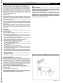
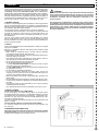
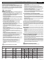
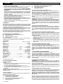
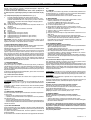
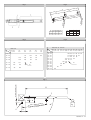
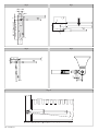
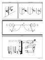
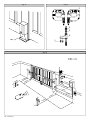
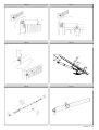
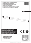
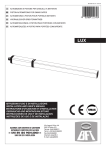
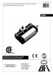
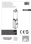
D811304 ver. 01 15-04-01
I
GB
AUTOMAZIONI A PISTONE PER CANCELLI A BATTENTE
PISTON AUTOMATIONS FOR SWING GATES
8 0 2 7 9 0 8 1 7 56 8 7
LUX
ISTRUZIONI D'USO E DI INSTALLAZIONE
INSTALLATION AND USER'S MANUAL
Via Lago di Vico, 44
36015 Schio (VI)
Tel.naz. 0445 696511
Tel.int. +39 0445 696533
Fax 0445 696522
Internet: www.bft.it
E-mail: [email protected]
LUX Ver. 01 - 1
2 - LUX Ver. 01
MANUALE D’USO
Nel ringraziarVi per la preferenza accordata a questo prodotto, la ditta è
certa che da esso otterrete le prestazioni necessarie al Vostro uso.
Leggete attentamente l’opuscolo “Avvertenze” ed il “Libretto istruzioni”
che accompagnano questo prodotto in quanto forniscono importanti indicazioni riguardanti la sicurezza, l’installazione, l’uso e la manutenzione.
Questo prodotto risponde alle norme riconosciute della tecnica e della
disposizioni relative alla sicurezza. Confermiamo che è conforme alle
seguenti norme: CAN/CSA-C22.2 No. 247-92 UL Std. No. 325 (Certificato
100400-1 in data 28 marzo 1994).
2) GENERALITA'
Pistone oleodinamico compatto e robusto, disponibile in svariate versioni
a seconda delle esigenze e del campo di utilizzo. Ci sono modelli con
blocchi idraulici e modelli senza blocchi (reversibili) che, per mantenere il
blocco , necessitano di elettroserratura. Lo sblocco di emergenza si attiva
utilizzando l'apposita chiave.
La forza di spinta si regola con estrema precisione mediante due valvole bypass che costituiscono la sicurezza antischiacciamento. Il funzionamento
a fine corsa è regolato elettronicamente nel quadro di comando mediante
temporizzatore.
Sono disponibili versioni speciali con rallentamento in fase di chiusura
(LUX R) ed il mod. LUX FC ideale per zone innevate o quando manca la
battuta d'arresto centrale delle ante del cancello (Vedere specifico manuale istruzioni).
2) SICUREZZA
L’automazione, se installata ed utilizzata correttamente, soddisfa il grado
di sicurezza richiesto.
Tuttavia è opportuno osservare alcune regole di comportamento per
evitare inconvenienti accidentali.
• Prima di usare l’automazione, leggere attentamente le istruzioni d’uso e
conservarle per consultazioni future.
• Tenere bambini, persone e cose fuori dal raggio d’azione dell’automazione,in particolare durante il funzionamento.
• Non lasciare radiocomandi o altri dispositivi di comando alla portata dei
bambini onde evitare azionamenti involontari dell’automazione.
• Non contrastare volontariamente il movimento dell’anta.
• Non tentare di aprire manualmente il cancello se:
Nel modello LUX-LUXL-LUXG-LUXGV non è stata sbloccata
l’elettroserratura con l’apposita chiave.
Nel modello LUXB-LUX2B non è stato azionato lo sblocco con l’apposita chiave (Fig.1).
• Non modificare i componenti dell’automazione.
• In caso di malfunzionamento, togliere l’alimentazione, attivare lo sblocco di emergenza per consentire l’accesso e richiedere l’intervento di un
tecnico qualificato (installatore).
• Per ogni operazione di pulizia esterna, togliere l’alimentazione di rete.
• Tenere pulite le ottiche delle fotocellule ed i dispositivi di segnalazione
luminosa. Controllare che rami ed arbusti non disturbino i dispositivi di
sicurezza (fotocellule).
• Per qualsiasi intervento diretto all’automazione, avvalersi di personale
qualificato (installatore).
• Annualmente far controllare l’automazione da personale qualificato.
ITALIANO
AVVERTENZE
Il buon funzionamento dell’operatore è garantito solo se vengono
rispettate i dati riportati in questo manuale. La ditta non risponde dei
danni causati dall’inosservanza delle norme di installazione e delle
indicazioni riportate in questo manuale.
Le descrizioni e le illustrazioni del presente manuale non sono
impegnative. Lasciando inalterate le caratteristiche essenziali del
prodotto, la Ditta si riserva di apportare in qualunque momento le
modifiche che essa ritiene convenienti per migliorare tecnicamente,
costruttivamente e commercialmente il prodotto, senza impegnarsi
ad aggiornare la presente pubblicazione.
Fig. 1
3) APERTURA MANUALE
Versioni con blocco idraulico (LUXB-LUX2B)
Nei casi di emergenza, per esempio in mancanza di energia elettrica, per
sbloccare il cancello, infilare la stessa chiave "C" usata per la regolazione
delle valvole by-pass nel perno "P" triangolare situato sotto l'attuatore (fig.
1) e ruotarla in senso antiorario. Il cancello è così apribile manualmente
imprimendo una velocità di spinta uguale a quella di apertura automatica.
Per ripristinare il funzionamento elettrico dell'attuatore, girare la chiave in
senso orario fino al completo bloccaggio del perno "P".
Versione senza blocco idraulico (LUX-LUXL-LUXG-LUXGV)
É sufficiente aprire l'elettroserratura con la relativa chiave e spingere
manualmente l'anta.
4) MANUTENZIONE E DEMOLIZIONE
La manutenzione dell’impianto va fatta eseguire regolarmente da
parte di personale qualificato. I materiali costituenti l’apparecchiatura e
il suo imballo vanno smaltiti secondo le norme vigenti.
LUX Ver. 01 - 3
ENGLISH
USER’S MANUAL
Thank you for buying this product, our company is sure that you will be more
than satisfied with the product’s performance. The product is supplied with
a “Warnings” leaflet and an “Instruction booklet”. These should both be
read carefully as they provide important information about safety, installation,
operation and maintenance. This product complies with the recognised
technical standards and safety regulations.We declare that this product is
in conformity with the following directives: CAN/CSA-C22.2 No. 247-92 UL
Std. No. 325 (Certificate: 100400-1 Date Issued: March 28, 1994).
2) GENERAL OUTLINE
A compact, sturdy oleodynamic piston, available in a wide range of models
to fit any need and field of operation. It is available in versions both with or
without (reversible) hydraulic lock, that need to be equipped with an electric
lock to hold the gate both closed and open.
The emergency release is obtained with the special key provided.
The adjustment of the pushing force is extremely precise and is performed
by means of two by-pass valves that act as an antisquash safety. The
operation at the end of the stroke is controlled electronically by a timer in
the control panel.
The LUX series includes special versions with slowdown in the closing
phase (LUX R) while the LUX FC series is especially suited to areas prone
to heavy snowfalls or where the central gate stop cannot be provided (see
specific instruction manual).
2) SAFETY
If correctly installed and used, this automation device satisfies the required
safety level standards.
However, it is advisable to observe some practical rules in order to avoid
accidental problems.
• Before using the automation device, carefully read the operation
instructions and keep them for future reference.
• Keep children, people and things outside the automation working area,
particularly during its operation.
• Keep radio control or other control devices out of children’s reach, in
order to avoid any unintentional automation activation.
• Do not intentionally oppose the leaf movement.
• Do not attempt to open the gate manually if:
- In mod. LUX-LUXL-LUXG-LUXGV the electric lock has not been
released by means of the appropriate key.
- In mod. LUXB-LUX2B the release has not been activated by means of
the appropriate key (fig.1).
• Do not modify the automation components.
• In case of malfunction, disconnect the power supply, activate the
emergency release to have access to the automation and request the
assistance of a qualified technician (installer).
• Before proceeding to any outside cleaning operation, disconnect the
power supply.
• Keep the photocell optical components and light signal devices clean.
• Check that the safety devices (photocells) are not obscured by branches
or shrubs.
• For any direct assistance to the automation system, request the help of
a qualified technician (installer).
• Have qualified personnel check the automation system once a year.
3) MANUAL OPENING
Versions with hydraulic lock (LUXB-LUX2B)
In case of emergency, for example during a power cut, the gate can be
released by inserting the same key “C” used to adjust the bypass valve into
the triangular pivot “P” found under the actuator (fig. 1) and turning it anticlockwise. The gate can then be opened manually following the same
speed as an automatic opening.
To restore the actuator to electrical operation, turn the key clockwise until
pivot “P” is locked.
Versions without hydraulic lock (LUX-LUXL-LUXG-LUXGV)
It is sufficient to open the electric lock with its key and move the
leaf manually.
4) MAINTENANCE AND DEMOLITION
The maintenance of the system should only be carried out by qualified
personnel regularly. The materials making up the set and its packing must
be disposed of according to the regulations in force.
4 - LUX Ver. 01
WARNINGS
Correct controller operation is only ensured when the data contained
in the present manual are observed. The company is not to be held
responsible for any damage resulting from failure to observe the
installation standards and the instructions contained in the
present manual.
The descriptions and illustrations contained in the present manual
are not binding. The Company reserves the right to make any alterations
deemed appropriate for the technical, manufacturing and commercial
improvement of the product, while leaving the essential product
features unchanged, at any time and without undertaking to update
the present publication.
Fig. 1
MANUALE PER L’INSTALLAZIONE
Nel ringraziarVi per la preferenza accordata a questo prodotto, la ditta è certa che da
esso otterrete le prestazioni necessarie al Vostro uso.
Leggete attentamente l’opuscolo “Avvertenze” ed il “Libretto istruzioni” che accompagnano questo prodotto in quanto forniscono importanti indicazioni riguardanti la
sicurezza, l’installazione, l’uso e la manutenzione. Questo prodotto risponde alle
norme riconosciute della tecnica e della disposizioni relative alla sicurezza. Confermiamo che è conforme alle seguenti norme: CAN/CSA-C22.2 No. 247-92 UL Std. No. 325
(Certificato 100400-1 in data 28 marzo 1994).
•
•
•
•
•
1) SICUREZZA GENERALE
ATTENZIONE! Una installazione errata o un uso improprio del prodot-to, può
creare danni a persone, animali o cose.
• Leggete attentamente l’opuscolo ”Avvertenze” ed il ”Libretto istruzio-ni” che
accompagnano questo prodotto, in quanto forniscono Importanti indicazioni
riguardanti la sicurezza, l’installazione, l’uso e la manutenzione.
• Smaltire i materiali di imballo (plastica, cartone, polistirolo, ecc.) secon-do quanto
previsto dalle norme vigenti. Non lasciare buste di nylon e
polistirolo a portata dei bambini.
• Conservare le istruzioni per allegarle al fascicolo tecnico e per consul-tazioni future.
• Questo prodotto è stato progettato e costruito esclusivamente per l’utilizzo indicato
in questa documentazione.
Usi non indicati in questa documentazione potrebbero essere fonte di danni al
prodotto e fonte di pericolo.
• La Ditta declina qualsiasi responsabilità derivante dall’uso improprio o diverso da
quello per cui è destinato ed indicato nella presente docu-mentazione.
• Non installare il prodotto in atmosfera esplosiva.
• La Ditta declina qualsiasi responsabilità dall’inosservanza della Buona
Tecnica nella costruzione delle chiusure (porte, cancelli, ecc.), nonché
dalle deformazioni che potrebbero verificarsi durante l’uso.
• Togliere l’alimentazione elettrica, prima di qualsiasi intervento sull’im-pianto.
Scollegare anche eventuali batterie tampone se presenti.
• Prevedere sulla rete di alimentazione dell’automazione, un interruttore
o un magnetotermico onnipolare con distanza di apertura dei contatti uguale o
superiore a 3mm.
• Verificare che a monte della rete di alimentazione, vi sia un interruttore
differenziale con soglia da 0.03A.
• Verificare se l’impianto di terra è realizzato correttamente: collegare tutte le parti
metalliche della chiusura (porte, cancelli, ecc.) e tutti i componenti dell’impianto
provvisti di morsetto di terra.
• Applicare tutti i dispositivi di sicurezza (fotocellule, coste sensibili, ecc.)
necessari a proteggere l’area da pericoli di schiacciamento, convogliamento,
cesoiamento.
• Applicare almeno un dispositivo di segnalazione luminosa (lampeggiante) in posizione visibile, fissare alla struttura un cartello di Attenzione.
• La Ditta declina ogni responsabilità ai fini della sicurezza e del buon funzionamento
dell’automazione se vengono impiegati componenti di altri produttori.
• Usare esclusivamente parti originali per qualsiasi manutenzione o riparazione.
• Non eseguire alcuna modifica ai componenti dell’automazione se non
espressamente autorizzata dalla Ditta.
• Istruire l’utilizzatore dell’impianto per quanto riguarda i sistemi di coman-do
applicati e l’esecuzione dell’apertura manuale in caso di emergenza.
• Non permettere a persone e bambini di sostare nell’area d’azione dell’automazione.
• Non lasciare radiocomandi o altri dispositivi di comando alla portata dei
bambini onde evitare azionamenti involontari dell’automazione.
• L’utilizzatore deve evitare qualsiasi tentativo di intervento o riparazione
dell’automazione e rivolgersi solo a personale qualificato.
• Tutto quello che non è espressamente previsto in queste istruzioni, non
è permesso.
ITALIANO
L’attuatore risulta idoneo per la tipologia costruttiva del cancello e per la classe di
utilizzo del cancello.
Tutti i punti di schiacciamento evidenti sono protetti o schermati.
L’apricancello è concepito per essere installato solo su cancelli utilizzati per il
passaggio di veicoli. Per i pedoni devono essere previsti accessi separati.
Il cancello deve essere installato in una posizione tale da garantire una distanza sufficiente tra il cancello e le strutture adiacenti durante l’apertura e la chiusura,
al fine di ridurre il rischio di intrappolamento.
I cancelli a battente non potranno essere aperti in aree di pubblico accesso.
Il cancello deve essere installato correttamente e deve funzionare
liberamente in entrambe le direzioni prima dell’installazione dell’apricancello. Non
serrare eccessivamente la frizione dell’attuatore o la valvola di sfiato della pressione per rimediare ad un cancello danneggiato.
IN CASO DI APRICANCELLI CON COMANDO UOMO PRESENTE:
• I comandi dell’apricancello devono essere posizionati in modo tale che l’utilizzatore
abbia una visuale completa dell’area del cancello quando il cancello è in movimento.
• Dovrà essere posizionato vicino ai comandi un cartello recante la scritta “AVVERTENZA” dalle lettere alte almeno 6,4 mm. e la seguente dichiarazione: “ Il cancello
in movimento è in grado di causare lesionii o morte - non azionate il cancello quando
il percorso non è libero”.
• Non dovranno essere utilizzati dispositivi di chiusura automatici (quali temporizzatori,
rilevatori di spira o dispositivi similari).
• Non dovrà essere collegato nessun altro dispositivo di attivazione.
I comandi devono essere sufficientemente lontani dal cancello in modo che l’utente non
possa venire a contatto con il cancello quando utilizza tali comandi. I comandi previsti
per il resettaggio dell’attuatore dopo due attivazioni successive del dispositivo/i contro
l’intrappolamento devono essere posizionati sulla linea visiva del cancello. I comandi
esterni o facilmente accessibili dovranno essere dotati di protezione al fine di impedirne
l’utilizzo non autorizzato.
I segnali di avvertenza e i cartelli devono essere installati in una posizione visibile
nell’area del cancello.
IN CASO DI ATTUATORI CHE UTILIZZANO UN SENSORE CON RILEVAMENTO
SENZA CONTATTO:
• Leggere le istruzioni sul posizionamento dei sensori senza contatto per ogni tipo di
applicazione.
• Provvedere affinché venga ridotto al minimo il rischio di intervento di disturbi come
quando, ad esempio, il veicolo fa scattare il sensore mentre il cancello è ancora in
movimento.
• Posizionare uno o più sensori senza contatto dove esiste il rischio di intrappolamento
o ostruzione, ad esempio lungo il perimetro raggiunto dal cancello in movimento.
IN CASO DI ATTUATORI CHE UTILIZZANO UN SENSORE CON RILEVAMENTO
A CONTATTO (COSTA SENSIBILE O EQUIVALENTE):
• Dovranno essere installati uno o più sensori di contatto sul punto di serraggio di
cancelli verticali a cardine per passaggio veicolare.
• Dovrà essere installato un sensore con contatto a circuito permanente i cui cablaggi
dovranno essere disposti in modo tale che la comunicazione tra il sensore e
l’apricancello non sia soggetta a danni meccanici.
• Dovrà essere installato un sensore con contatto senza fili quale ad esempio un
sensore che trasmette segnali di frequenze radio (RF) all’apricancello per le
funzioni di protezione contro l’intrappolamento nei casi in cui la trasmissione dei
segnali non sia ostacolata o impedita dalla struttura dell’edificio, dal paesaggio
naturale o da ostacoli similari. Il sensore con contatto senza fili dovrà funzionare
conformemente alle condizioni per l’utilizzo finale previste.
IMPORTANTI PRESCRIZIONI DI SICUREZZA
ATTENZIONE: al fine di ridurre il rischio di danni fisici o morte:
INSTALLARE L’APRICANCELLO SOLO QUANDO:
TABELLA 1
MOD
TIPO DI BLOCCO
POMPA TEMPO CORSA
UTILE
l/min
gal/min
LUX
elettroserratura
1.2
LUX B
idraulico chiusura
1.2
LUX 2B
idraulico chius.-aperto
1.2
LUX L
elettroserratura
0.6
LUX G
elettroserratura
0.6
LUX GV
elettroserratura
1.2
0,317
0,317
0,158
0,158
0,158
0,317
ANTA MAX
(m)
17
2
17
2
17
2
33
2-4
48
5-2
28
3-5
CORSA
(kg)
(lb)
(ft)
6.56
6.56
300
utile
270
661.4
270
300
661.4
300
6.56
661.4
6.56 300 661.4
13.12 500 1102.3
16.40 300 661.4
6.56 500 1102.3
9.84 300
16.40
661.4
270
270
390
390
10.62
10.62
10.62
10.62
15.35
15.35
(mm)
(in)
totale
290
290
290
290
410
410
MANOVRE
24 H
11.41
500
11.41
500
11.41
500
11.41
16.14
16.14
350
250
500
LUX Ver. 01 - 5
ITALIANO
•
•
•
•
•
•
•
•
MANUALE PER L’INSTALLAZIONE
Leggere e osservare tutte le istruzioni.
Non permettere ai bambini di utilizzare o giocare con i comandi del
cancello. Tenere il telecomando fuori dalla portata dei bambini.
Tenere lontani oggetti e persone dal cancello. NON E’ PERMESSO
ATTRAVERSARE IL PERCORSO ESEGUITO DAL CANCELLO IN
MOVIMENTO.
Controllare mensilmente il corretto funzionamento del cancello. Il cancello DEVE
invertire marcia in caso di contatto con oggetti rigidi e deve fermarsi quando un
oggetto attiva i sensori senza contatto. Dopo aver regolato la forza o il finecorsa,
ricontrollare l’apricancello.
La mancata regolazione e l’omissione del successivo controllo dell’apricancello
possono aumentare il rischio di danni fisici e di morte.
Utilizzare lo sblocco di emergenza solo a cancello fermo.
ESEGUIRE UNA MANUTENZIONE REGOLARE DEL CANCELLO.Leggere il
manuale dell’utilizzatore. Eventuali riparazioni alle parti meccaniche del cancello
devono essere eseguite da personale qualificato.
L’entrata è riservata ai veicoli. Prevedere un’entrata separata per i pedoni.
Conservare le presenti istruzioni.
2) GENERALITA'
Pistone oleodinamico compatto e robusto, disponibile in svariate versioni a seconda
delle esigenze e del campo di utilizzo. Ci sono modelli con blocchi idraulici e modelli
senza blocchi (reversibili) che, per mantenere il blocco , necessitano di elettroserratura.
Lo sblocco di emergenza si attiva utilizzando l'apposita chiave.
La forza di spinta si regola con estrema precisione mediante due valvole by-pass che
costituiscono la sicurezza antischiacciamento. Il funzionamento a fine corsa è regolato
elettronicamente nel quadro di comando mediante temporizzatore.
Sono disponibili versioni speciali con rallentamento in fase di chiusura (LUX R) ed il
mod. LUX FC ideale per zone innevate o quando manca la battuta d'arresto centrale
delle ante del cancello (Vedere specifico manuale istruzioni).
3) PARTI PRINCIPALI DELL'AUTOMAZIONE (fig. 1)
M)
Motore monofase 2 poli protetto da disgiuntore termico
P)
Pompa idraulica a lobi
D)
Distributore con valvole di regolazione
C)
Cilindro con pistone
Componenti in dotazione: attacchi al pilastro e al cancello - chiave di sblocco e
regolazione bypass - condensatore di marcia - manuale istruzione
4) DATI TECNICI
Alimentazione: ................................................................... 110Vac ±10% - 60 Hz (*)
Motore: ..................................................................................................... 2800 min-1
Potenza assorbita: ........................................................................................... 250W
Condensatore: ................................................................................................ 6,3 µF
Corrente assorbita: ............................................................................................ 1,4A
Max pressione: ...................................................... 30 bar........................62656 lb/ft2
Portata pompa: .............................................................................. Vedere Tabella 1
Forza di spinta: ..................................................... 3000 N..........................674.42 lbf
Forza di trazione: .................................................. 2600 N..........................584.50 lbf
Corsa utile: .................................................................................... Vedere Tabella 1
Reazione all'urto: ............................................................................. frizione idraulica
Manovra manuale: ......................................................................... chiave di sblocco
Max N° manovre in 24h: ................................................................ Vedere Tabella 1
Protezione termica: ................................................ 160° C................................320°F
Ccondizioni ambientali: ............................. -10° C ÷ 60° C...........................14-140°F
Grado di protezione: ......................................................................................... IP 57
Peso operatore: ....................................................... 8,7 kg............................19.18 lb
Dimensioni: ................................................................................................ vedi fig. 2
Olio: ............................................................................................................... Idrolux
(*) Tensioni speciali a richiesta
5) INSTALLAZIONE DELL'ATTUATORE
5.1) Verifiche preliminari
Controllare:
• Che la struttura del cancello sia sufficientemente robusta.In ogni caso, l'attuatore
deve spingere l’anta in un punto rinforzato.
• Che le ante si muovano manualmente e senza sforzo per tutta la corsa.
• Che siano installate le battute d'arresto delle ante.
• Se il cancello non è di nuova installazione, controllare lo stato di usura di tutti i
componenti.
Sistemare o sostituire le parti difettose o usurate.
L’affidabilità e la sicurezza dell’automazione è direttamente influenzato dallo stato della
struttura del cancello.
5.2) Quote di installazione
Le quote di installazione si ricavano dalla tabella del rispettivo modello (fig.3-4) e
facendo riferimento allo schema di fig.5 .
Lo schema di fig.5 utilizza le seguenti convenzioni:
P
staffa posteriore di fissaggio al pilastro
F
forcella anteriore di fissaggio dell'anta
a-b
quote per determinare il punto di fissaggio della staffa "P"
C
valore dell'interasse di fissaggio (vedi fig. 2)
D
lunghezza del cancello
6 - LUX Ver. 01
X
Z
kg
α°
distanza dall'asse del cancello allo spigolo del pilastro
valore sempre superiore a 45 mm (b - X)
peso max dell'anta (Tabella 1)
angolo d'apertura dell'anta
5.3) Come interpretare le misure d'installazione (fig.3-4)
Dalle tabelle (fig.3-4) è possibile scegliere valori di "a" e "b" in funzione dei gradi α° di
apertura che si desiderano ottenere. In ogni tabella, sono evidenziati valori di "a" e "b"
ottimali per una apertura di α° =90° a velocità costante; in questa condizione, la somma
di "a" e "b" è uguale al valore della corsa utile "Cu" (fig.2).
Se si utilizzano valori di "a" e "b" troppo diversi tra loro, il movimento dell'anta non è
costante e la forza di trazione-spinta e la velocità di movimento, variano durante la
manovra.
Per valori massimi di "a" e "b", è massima la forza sviluppata dal pistone; questa
condizione è utile in particore per cancelli pesanti ed ante lunghe.
ATTENZIONE! Le versioni LUX con stelo dotato di occhiello di regolazione, consentono di allungare o accorciare lo stelo di circa 6mm solo se prima dell'installazione lo
si è fissato alle quote indicate in fig.9; ad installazione ultimata, questa regolazione,
consente di correggere la corsa dello stelo; in fig.10, è indicata l'oscillazione rispetto
all'asse orizzontale, che possono assumere i mod.LUX dotati di snodo anteriore e
posteriore.
5.4) Accorgimenti per installazioni particolari
Fig.6 - Necessita realizzare una nicchia per accogliere l'operatore quando l'anta è
completamente aperta; in fig.6 sono riportate le misure di nicchia per i vari modelli LUX.
Fig.7 - Se la quota "a" risulta superiore ai valori riportati nelle tabelle di installazione,
è necessario spostare il cardine dell'anta, oppure ricavare una nicchia nel pilastro come
in fig.8.
5.5) Ancoraggio degli attacchi al pilastro ed all'anta del cancello.
Fissare l'attacco "P" fig.11 al pilastro con una robusta saldatura; allo stesso modo
saldare all'anta la forcella "F" all'interasse "C" indicato in fig.5 e facendo attenzione che
l'attuatore risulti perfettamente orizzontale (livella "L" fig.11) rispetto al piano di
movimento del cancello.
• Se il pilastro è in muratura, la piastra "PF" dovrà essere saldata ad una base di
metallo (mod.PLE) e ancorata in profondità mediante idonee zanche "Z" saldate sul
retro della stessa (fig. 12).
• Se il pilastro è di pietra, la piastra "PF", saldata ad una base di metallo (mod.PLE)
può essere fissata con quattro tasselli metallici ad espansione "T" (fig. 13); se il
cancello è grande, si consiglia di saldare la piastra "PF" in una base di forma
angolare (fig. 14).
6) BATTUTE D'ARRESTO DELLE ANTE AL SUOLO
Per il corretto funzionamento dell'attuatore è obbligatorio utilizzare delle battute di
arresto "F" sia in apertura che in chiusura come indicato in fig.15.
Le battute d'arresto delle ante, devono evitare che lo stelo dell'attuatore vada a
finecorsa. In fig.16, sono riportate le quote per verificare la corretta installazione con
attuatore in spinta o trazione.Devono essere posizionate in modo da mantenere un
margine di corsa dello stelo di circa 5-10mm; ciò evita possibili anomalie di funzionamento
7) APPLICAZIONE DELL'ELETTROSERRATURA
É necessaria solo nei modelli senza blocco idraulico in chiusura.
L'elettroserratura mod. EBP (fig.17) è costutuita da un elettromagnete a servizio
continuo con aggancio al suolo. In questo dispositivo l'eccitazione rimane per tutto il
tempo di lavoro del motoriduttore consentendo al dente di aggancio "D" di arrivare in
battuta di chiusura sollevato senza opporre la minima resistenza; tale proprietà
permette di diminuire il carica di spinta in chiusura migliorando la sicurezza
antischiacciamento.
8) MONTAGGIO DEL PRESSACAVO (fig.18)
ATTENZIONE: Fissare la basetta "B" al fondello "F" con le viti "V" in dotazione.
Posizionare il gommino "G" nell'apposita sede nella basetta "B". Infilare il dado "D" nel
cavo di alimentazione e poi nella basetta "B", come a disegno. Fissare il dado "D" fino
a bloccare il cavo di alimentazione.
N.B. La basetta "B" può essere montata sul fondello "F", sia a sinistra che a destra a
seconda della necessità, come a disegno.Nella parte inferiore della basetta "B" è
ricavata una spirale per l'eventuale aplicazione di una guaina spiralata "GS" in pvc (Ø
= 12).
9) PREDISPOSIZIONE DELL' IMPIANTO ELETTRICO
Predisporre l’impianto elettrico (fig.19) facendo riferimento alle norme vigenti per gli
impianti elettrici. Tenere nettamente separati i collegamenti di alimentazione di rete dai
collegamenti di servizio (fotocellule, coste sensibili, dispositivi di comando ecc.).
Attenzione! Per il collegamento alla rete, utilizzare cavo multipolare di sezione
minima 3x1.5mm2 (16AWG) e del tipo previsto dalle normative precedentemente
citate (UL1015).
Realizzare i collegamenti dei dispositivi di comando e di sicurezza in armonia con le
norme per l’impiantistica precedentemente citate. In fig.19 è riportato il numero di
collegamenti e la sezione per una lunghezza dei cavi di alimentazione fino a 328 ft (100
metri); per lunghezze superiori, calcolare la sezione per il carico reale dell’automazione. Quando le lunghezze dei collegamenti ausiliari superano i 164 ft (50 metri) o
MANUALE PER L’INSTALLAZIONE
passano in zone critiche per i disturbi, è consigliato disaccoppiare i dispositivi di
comando e di sicurezza con opportuni relè.
Le scatole di derivazione dell’alimentazione devono essere predisposte ad
un’altezza superiore a quella degli operatori, per evitare fuoriuscite di olio (Fig.
19).
9.1) Componenti principali per una automazione sono (fig.19):
I
Interruttore onnipolare omologato con apertura contati di almeno
3mm provvisto di protezione contro i sovraccarichi ed i corto circuiti, atto a
sezionare l’automazione dalla rete. Se non presente, prevedere a monte del
l’automazione un interruttore differenziale omologato di adeguata portata e
soglia da 0,03A.
Qr) Quadro comando e ricevente incorporata.
SPL) Scheda di preriscaldamento per funzionamento a temperature inferiori ai 5°C
(opzionale).
S)
Selettore a chiave.
AL) Lampeggiante con antenna accordata e cavo RG58.
M)
Attuatore
E)
Elettroserratura.
Fte) Coppia fotocellule esterne (parte emittente)
Fre) Coppia fotocellule esterne (parte ricevente)
Fti) Coppia fotocellule interne con colonnine CF (parte emittente)
Fri) Coppia fotocellule interne con colonnine CF (parte ricevente)
T)
Trasmittente 1-2-4 canali
IMPORTANTE: Prima di far funzionare elettricamente l'attuatore togliere la vite di
sfiato "S" (fig.20) posta sotto il blocco snodo e conservarla per eventuale riutilizzo.
Togliere la vite di sfiato "S" solo quando l'attuatore è installato.
10) REGOLAZIONE DELLA FORZA DI SPINTA
E' regolata da due valvole contraddistinte dalla scritta "close" e "open" rispettivamente per la regolazione della forza di spinta in chiusura ed in apertura.
Ruotando le valvole verso il segno"+", aumenta la forza trasmessa; ruotando le valvole
verso il segno"-", diminuisce
Per una buona sicurezza antischiacciamento, la forza di spinta deve essere di poco
superiore a quella necessaria per muovere l'anta sia in chiusura che in apertura; la
forza, misurata in punta all'anta, non deve comunque superare i limiti previsti dalle
norme nazionali vigenti. In nessun caso comunque si devono chiudere completamente
le valvole dei by-pass. L'attuatore non è provvisto di finecorsa elettrici. Pertanto i motori
si spengono quando è terminato il tempo di lavoro impostato nella centralina di
comando. Tale tempo di lavoro, deve essere di circa 2-3 secondi superiore al momento
in cui le ante incontrano le battute d'arresto al suolo.
11) APERTURA MANUALE
11.1) Versioni con blocco idraulico
Nei casi di emergenza, per esempio in mancanza di energia elettrica, per sbloccare il
cancello, infilare la stessa chiave "C" usata per la regolazione delle valvole by-pass nel
perno "P" triangolare situato sotto l'attuatore (fig. 21) e ruotarla in senso antiorario. Il
cancello è così apribile manualmente imprimendo una velocità di spinta uguale a quella
di apertura automatica.
Per ripristinare il funzionamento elettrico dell'attuatore, girare la chiave in senso orario
fino al completo bloccaggio del perno "P".
11.2) Versione senza blocco idraulico
É sufficiente aprire l'elettroserratura con la relativa chiave e spingere manualmente
l'anta.
12) POSIZIONAMENTO COPERTURE
ATTENZIONE: Nei modelli LUX G, può essere necessario aggiungere uno spessore
di circa 25mm sotto la forcella "F" (fig.23) per evitare possibili collisioni durante il
movimento.
La copertura "C" di tutti i modelli LUX diventa destra o sinistra invertendo la posizione
del tappo "T" (fig.24).
La protezione dei BY-pass (fig.25), va messa in posizione e poi incastrata sotto il
copristelo "C".
13) VERIFICA DELL'AUTOMAZIONE
Prima di rendere definitivamente operativa l'automazione, controllare scrupolosamente quanto segue:
• Verificare che tutti i componenti siano fissati saldamente.
• Controllare il corretto funzionamento di tutti i dispositivi di sicurezza (fotocellule,
costa pneumatica, ecc).
• Verificare il comando della manovra di emergenza.
• Verificare l'operazione di apertura e chiusura con i dispositivi di comando applicati.
• Verificare la logica elettronica di funzionamento normale (o personalizzata) nella
centralina di comando.
14) USO DELL'AUTOMAZIONE
Poichè l'automazione può essere comandata a distanza mediante radiocomando o
pulsante di Start, è indispensabile controllare frequentemente la perfetta efficienza di
tutti i dispositivi di sicurezza.
Per qualsiasi anomalia di funzionamento, intervenire rapidamente avvalendosi di
personale qualificato.
Si raccomanda di tenere i bambini a debita distanza dal raggio d'azione dell'automa-
ITALIANO
zione.
15) COMANDO
Il comando può essere di diverso tipo (manuale, con radiocomando, controllo accessi
con badge magnetico, ecc.) secondo le necessità e le caratteristiche dell'installazione.
Per i vari sistemi di comando, vedere le relative istruzioni.
Gli utilizzatori dell'automazione devono essere istruiti al comando e all'uso.
16) MANUTENZIONE
Per qualsiasi manutenzione all'operatore, togliere alimentazione al sistema.
• Verificare periodicamente se ci sono perdite d'olio.
Per effettuare il rabbocco olio procedere come segue:
a) Avvitare la vite di sfiato (fig.20) e smontare l'operatore dal cancello.
b) Far rientrare completamente lo stelo.
c) Mettere l'operatore in posizione verticale e svitare il tappo "O" (fig.18).
d) Rabboccare con olio di uguale tipo fino a sommergere il cuscinetto del
motore che si intravede sotto il tappo "O".
e) Chiudere il tappo "O" e rimontare l'operatore nel cancello.
f) Togliere la vite di sfiasto.
g) Eseguire 2 manovre complete recuperando l'olio in eccedenza che esce
dallo sfiato.
• Verificare i dispositivi di sicurezza del cancello e della motorizzazione.
• Per qualsiasi anomalia di funzionamento non risolta, togliere alimentazione al
sistema e chiedere l'intervento di personale qualificato (installatore).
Nel periodo di fuori servizio, attivare lo sblocco manuale per consentire
l'apertura e la chiusura manuale.
17) INCONVENIENTI E RIMEDI
17.1) Funzionamento difettoso del motoriduttore
• Verificare con apposito strumento la presenza di tensione ai capi del motoriduttore
dopo il comando di apertura o chiusura.
Se il motore vibra ma non gira, può essere:
• sbagliato il collegamento del filo comune C, (in ogni caso è di colore celeste).
• non è collegato il condensatore di marcia ai due morsetti di marcia.
• se il movimento dell'anta, è contrario a quello che dovrebbe essere, invertire i
collegamenti di marcia del motore nella centralina.
ARRESTI ANTE; quando il tempo di lavoro impostato nella centralina, è insufficente,
può succedere che le ante non completino la loro corsa. Alzare legermente il tempo
di lavoro nella centralina.
17.2) Funzionamento difettoso degli accessori elettrici
Tutti i dispositivi di comando e di sicurezza, in caso di guasto, possono causare
anomalie di funzionamento o blocco dell'automazione stessa.
Se la centralina di comando è dotata di autodiagnostica, individuare il diffetto. In caso
di guasto, è opportuno scollegare uno ad uno tutti i dispositivi dell'automazione, fino ad
individuare quello che causa il diffetto. Dopo averlo sostituito o riparato, ripristinare tutti
i dispositivi precedentemente scollegati. Per tutti i dispositivi installati, fare riferimento
al rispettivo manuale istruzione.
ATTENZIONE: L'intervento deve essere eseguito da personale qualificato. Durante
le operazioni di manutenzione, la zona operativa del cancello deve essere opportunamente segnalata e transennata in modo da evitare pericoli per persone, animali, cose.
AVVERTENZE:
Il buon funzionamento dell'operatore è garantito solo se vengono rispettate i dati
riportati in questo manuale.
La ditta non risponde dei danni causati dall'innosservanza delle norme di sicurezza, di
installazione, di buona tecnica, delle indicazioni riportate in questo manuale.
18) DEMOLIZIONE
Attenzione: Avvalersi esclusivamente di personale qualificato.
L’eliminazione dei materiali va fatta rispettando le norme vigenti.
Nel caso di demolizione dell’automazione non esistono particolari pericoli
o rischi derivanti dall’automazione stessa.
È opportuno, in caso di recupero dei materiali, che vengano separati per
tipologia (parti elettriche - rame - alluminio - plastica - ecc.).
19) SMANTELLAMENTO
Attenzione: Avvalersi esclusivamente di personale qualificato.
Nel caso l’automazione venga smontata per essere poi rimontata in altro
sito bisogna:
• Togliere l’alimentazione e scollegare tutto l’impianto elettrico esterno.
• Nel caso alcuni componenti non possano essere rimossi o risultino danneggiati,
provvedere alla loro sostituzione.
Le descrizioni e le illustrazioni del presente manuale non sono impegnative.
Lasciando inalterate le caratteristiche essenziali del prodotto, la Ditta si riserva
di apportare in qualunque momento le modifiche che essa ritiene convenienti
per migliorare tecnicamente,
costruttivamente e commercialmente il prodotto, senza impegnarsi ad aggiornare la presente pubblicazione.
LUX Ver. 01 - 7
ENGLISH
INSTALLATION MANUAL
Thank you for buying this product, our company is sure that you will be more than
satisfied with the product’s performance. The product is supplied with a “Warnings”
leaflet and an “Instruction booklet”. These should both be read carefully as they
provide important information about safety, installation, operation and maintenance.
This product complies with the recognised technical standards and safety
regulations.We declare that this product is in conformity with the following directives:
CAN/CSA-C22.2 No. 247-92 UL Std. No. 325 (Certificate: 100400-1 Date Issued:
March 28, 1994).
•
•
•
•
1) GENERAL SAFETY
•
WARNING! An incorrect installation or improper use of the product can
cause damage to persons, animals or things.
• The “Warnings” leaflet and “Instruction booklet” supplied with this product
should be read carefully as they provide important information about safety,
installation, use and maintenance.
• Scrap packing materials (plastic, cardboard, polystyrene etc) according to the
provisions set out by current standards. Keep nylon or polystyrene bags out of
children’s reach.
• Keep the instructions together with the technical brochure for future reference.
• This product was exclusively designed and manufactured for the use specified in
the present documentation. Any other use not specified in this documentation
could damage the product and be dangerous.
• The Company declines all responsibility for any consequences resulting from
improper use of the product, or use which is different from that expected and
specified in the present documentation.
• Do not install the product in explosive atmosphere.
• The Company declines all responsibility for any consequences resulting from
failure to observe Good Technical Practice when constructing closing structures
(door, gates etc.), as well as from any deformation which might occur during use.
• Disconnect the electrical power supply before carrying out any work on the
installation. Also disconnect any buffer batteries, if fitted.
• Fit an omnipolar or magnetothermal switch on the mains power supply, having a
contact opening distance equal to or greater than 3mm.
• Check that a differential switch with a 0.03A threshold is fitted just before the power
supply mains.
• Check that earthing is carried out correctly: connect all metal parts for closure
(doors, gates etc.) and all system components provided with an earth terminal.
• Fit all the safety devices (photocells, electric edges etc.) which are needed to
protect the area from any danger caused by squashing, conveying and shearing.
• Position at least one luminous signal indication device (blinker) where it can be
easily seen, and fix a Warning sign to the structure.
• The Company declines all responsibility with respect to the automation
safety and correct operation when other manufacturers’ components are
used.
• Only use original parts for any maintenance or repair operation.
• Do not modify the automation components, unless explicitly authorised by the
company.
• Instruct the product user about the control systems provided and the manual
opening operation in case of emergency.
• Do not allow persons or children to remain in the automation operation area.
• Keep radio control or other control devices out of children’s reach, in order to avoid
unintentional automation activation.
• The user must avoid any attempt to carry out work or repair on the automation
system, and always request the assistance of qualified personnel.
• Anything which is not expressly provided for in the present instructions, is not
allowed.
INSTALL THE GATE OPERATOR ONLY WHEN:
The operator is appropriate for the construction of the gate and the usage Class
of the gate,
All exposed pinch points are eliminated or guarded,
The operator is intended for installation only on gates used for vehicles. Pedestrians
must supplied with a separate access opening,
The gate must be installed in a location so that enough clearance is supplied
between the gate and adjacent structures when opening and closing to reduce the
risk of entrapment. Swinging gates shall not open into public access areas,
The gate must be properly installed and work freely in both directions prior to the
installation of the gate operator. Do not over-tighten the operator clutch or presure
relief valve to compensate for a damaged gate.
FOR GATE OPENERS WITH HOLD-TO-RUN CONTROL:
• The gate operator controls must be placed so that the user has full view of the gate
area when the gate is moving,
• A sign with the message “WARNING” must be positioned near the controls. The
characters for the writing should be at least 6.4 mm high. The following statement
should also be indicated: “Moving Gate Has the Potential of Inflicting Injury or
Death - Do Not Start Gate Unless Path is Clear”.
• An automatic closing device (such as a timer, loop sensor, or similare device) shall
not be employed
• No other activation device shall be connected.
Controls must be far enough from the gate so that the user is prevented from coming
in contact with the gate while operating the controls. controls intended to be used to
reset an operator after 2 sequential activations of the entrapment protection device
or devices must be located in the line-of-sight of the gate. Outdoor or easly accesible
controls shall have a security feature to prevent unauthorized use.
All warnings signs and placards must be installed where visible in the area of the gate.
FOR GATE OPENERS PROVIDED WITH SENSOR FOR CONTACT-FREE
DETECTION:
• See instructions on the placement of non contact sensor for each type of
application,
• Care shall be exercised to reduce the risk of nuisance tripping, such as when a
vheicle, trips the sensor while the gate is still moving, and
• One or more non-contact sensor shall be located where the risk of entrapment or
obstruction exist, such as the perimeter reachable by a moving gate.
FOR GATE OPENERS PROVIDED WITH CONTACT DETECTION (RUBBER
EDGE OR SIMILAR):
• On or more contact sensor shall be located at the pinch point of a vehicular vertical
pivot gate.
• A hardwired contact sensor shall be located and its wiring arranged so that the
communication between the sensor and the gate operator is not subjected to
mechanical damage.
• A wireless contact sensor such as one that transimts radio frequency (RF) signals
the gate operator for entrapment protection functions shall be located where the
transimission of the signals are not obscrtucted or impeded y building structure,
natural landscaping or similar obstruction. A wireless contact sensor shall function
under the intended end-use conditions.
•
•
IMPORTANT SAFETY INSTRUCTIONS
WARNINGS: to reduce the risk of injury or death:
Read and follow all instructions.
Never let children operate or play with gate control. Keep the remote control away
TABLE 1
PUMP
MOD
TYPE OF BLOCK
l/min
gal/min
LUX
electric lock
1.2
LUX B
hydraulic closing
1.2
LUX 2B
hydraulic clos. - open
1.2
LUX L
electric lock
0.6
LUX G
electric lock
0.6
LUX GV
electric lock
1.2
8 - LUX Ver. 01
0,317
0,317
0,158
0,158
0,158
0,317
WORKING
TIME (S)
MAX WING
(m)
17
2
17
2
17
2
33
2-4
48
5-2
28
3-5
STROKE
(kg)
(ft)
6.56
(lb)
300
661.4
300
6.56
661.4
300
6.56
6.56
13.12
16.40
6.56
9.84
16.40
working
270
2 70
2 70
661.4
300 661.4
500 1102.3
300 661.4
500 1102.3
300
270
390
390
661.4
(mm)
10.62"
10.62"
10.62"
10.62"
15.35"
15.35"
(in)
tot
290
290
290
290
410
410
11.41"
11.41"
11.41"
11.41"
16.14"
16.14"
MANOEUVRES
24 H
500
500
500
350
250
500
INSTALLATION MANUAL
•
•
•
•
•
•
from children.
Always keep people and objects away from the gate. NO ONE SHOULD
CROSS THE PATH OF THE MOVING GATE.
Test the gate operator montly. The gate MUST reverse on contact with a rigid
object activates the non-contact sensor. After adjusting the force or the limit of
travel, reset the gate operator. Failure to adjust and retest the gate operator
properly can increase the risk of injury or death.
Use the emergency realease only when the gate is not moving.
KEEP GATES PROPERLY MAINTAINED. Read the owners manual. Have a
qualified service person make repairs to gate hardware.
The entrance is for veichles only. Pedestrians must use separate entrance.
Save these instructions.
2) GENERAL OUTLINE
A compact, sturdy oleodynamic piston, available in a wide range of models to fit any
need and field of operation. It is available in versions both with or without (reversible)
hydraulic lock, that need to be equipped with an electric lock to hold the gate both
closed and open.
The emergency release is obtained with the special key provided.
The adjustment of the pushing force is extremely precise and is performed by means
of two by-pass valves that act as an antisquash safety. The operation at the end of
the stroke is controlled electronically by a timer in the control panel.
The LUX series includes special versions with slowdown in the closing phase (LUX
R) while the LUX FC series is especially suited to areas prone to heavy snowfalls or
where the central gate stop cannot be provided (see specific instruction manual).
3) THE MAIN PARTS IN THE AUTOMATION (fig. 1)
M)
Single phase 2 pole motor protected by thermal circuit breaker
P)
Hydraulic lobe pump
D)
Fluid distributor with adjustment valves
C)
Cylinder with piston
Standard components:
• gate post and gate brackets - release key and bypass adjustment
• drive capacitor - instruction booklet.
4) TECHNICAL SPECIFICATIONS
Power supply: ................................................................. 110Vac ±10% - 60 Hz (*)
Motor: .................................................................................................... 2800 min-1
Power absorption: ......................................................................................... 250W
Capacitor: .................................................................................................... 6.3 µF
Current absorption ......................................................................................... :1.4A
Max. pressure: .................................................... 30 bar........................62656 lb/ft2
Pump delivery: .................................................................................... See Table 1
Pushing force: ................................................... 3000 N..........................674.42 lbf
Pulling force: ...................................................... 2600 N..........................584.50 lbf
Working stroke: .................................................................................. See Table 1
Impact reaction: ............................................................................. hydraulic clutch
Manual manoeuvres: ...................................................................... by release key
Max. no. manoeuvres in 24: ................................................................ See table 1
Thermal protection: ............................................. 160° C................................320°F
Ambient temperature: ............................. -10° C ÷ 60° C...........................14-140°F
Protection: ..................................................................................................... IP 57
Controller weight: .................................................. 8,7 kg............................19.18 lb
Dimensions ............................................................................................. :see fig. 2
Circuit oiI .................................................................................................... :idrolux
(*) Special voltages on request
5) INSTALLATION OF THE ACTUATOR
5.1) Preliminary checks
Check:
• that the structure of the gate is rigid and strong enough. In any case, the actuator
must push against a reinforced point in the leaf
• that the leaves move manually without excessive effort for the whole of their stroke
• that the door stops are mounted on the leaves
• If the gate being installed is not new, check whether its components are
worn.
Repair or replace any worn or damaged parts.
Automation reliability and safety are directly influenced by the condition of the gate’s
structure.
5.2) Installation values
The values to be known for installation can be found in the table related to the model being
installed (fig. 3-4), with reference also to the diagram in fig. 5.
The diagram in fig. 5 uses the following legend:
P
Gate-post fastening rear bracket
F
Leaf fastening front fork
a-b “P” bracket installation values
C
Distance between fixing points (see fig. 2)
D
Gate length
X
Z
kg
α°
ENGLISH
Distance from gate axis to the edge of the post
always over 45 mm (b - X)
max. weight of leaf (Table 1)
leaf opening in degrees
5.3) How to read the installation dimensions (fig- 3-4)
From the tables (fig. 3-4), select “a” and “b” according to the angle in degrees α° that
the gate has to open. Each table shows the ideal value for “a” and “b” for an opening
of α° = 90° at constant speed.
In this condition, the sum of “a” plus “b” gives the value of the working stroke “Cu” (fig.
2).
If there is too large a difference between “a” and “b”, the leaf will not travel smoothly
and the pushing or pulling force will fluctuate during its stroke.
When “a” and “b” are at their maximum, the piston develops the maximum force. This
condition is particularly useful for heavy gates or gates with very long leaves.
WARNING! The LUX models having a rod with adjustment ball joint enable the rod
to be lengthened or shortened by about 6 mm., but only if it is set in the position shown
in fig. 9 before being installed. When installed, this adjustment will allow for correcting
the stroke of the rod. Fig. 10 shows the oscillation to which the LUX models with front
and rear joint are subject with respect to the horizontal axis.
5.4) Off-standard installations
Fig. 6 - need for a recess to house the controller when the leaf is completely
opened;Fig. 6 gives the size of the recess for the different LUX models.
Fig. 7 - if the “a” value is higher than the values listed in the installation tables, the leaf’s
hinge pivot should be shifted, or a recess be made in the gate-post (fig. 8).
5.5) Mounting the brackets to the gate-post and to the gate-leaf.
Fix the bracket “P” (fig. 10) to the gate-post with a good welding.
The fork “F” should be welded in the same way to the gate leaf along the distance “C”
as shown in fig. 5, taking care that the actuator is perfectly horizontal (level “L” fig. 10)
to the line of travel of the gate.
• If the gate-post is in brick, the plate “PF” must be welded to a metal base (mod.
PLE) and set soundly into the post using adequately sized cramps “Z” welded to
the back of the plate (fig. 12).
• If the gate-post is in stone, the plate “PF” welded to a metal base (mod. PLE) can
be fixed with four metal expansion plugs “T” (fig. 13). If a larger gate is being
installed it would be better to weld the plate “PF” to an angular base (fig. 14).
6) GROUND GATE STOPS
For the controller to operate correctly the gate stops “F” must be used both in opening
and closing, as shown in fig. 15.
The gate stops should prevent the rod of the actuator from reaching its end of stroke
. Fig. 16 gives the values which ensure a perfect installation when the actuator is
performing the pushing or pulling function. They must be placed so that about a 5-10
mm margin of travel is maintained in the rod. This margin prevents any malfunctions.
7) FITTING THE ELECTRIC LOCK
This is only necessary on models without a hydraulic lock at closing end of
stroke.
The electric lock mod. EBP (fig. 17) consists of a continuous electromagnet with
ground catch. As long as the gearmotor is operating, this device features a non-stop
excitation and maintains the bolt “D” lifted until it reaches the closing end of stroke
without creating any friction. This characteristic enables the pushing force to be
reduced in closing which will improve the antisquash safety level.
7) MOUNTING THE CABLE-CLAMP (fig. 18)
WARNING! Fix the board “B” to the base “F” with the screws “V” provided. Place the
rubber “G” in its seat in the board “B”. Slide the nut “D” onto the power cable and pass
the cable over board “B” as shown in the picture Tighten nut “D” until the power cable
is clamped.
N.B. The board “B” can be fitted onto both the right and left of the base “F”, as required
(see picture).
The bottom of board “B” has a spiralled recess to eventually receive a spiralled sheath
“GS” in PVC (Ø = 12).
9) THE ELECTRICAL PLANT SET-UP
Set up the electrical installation as shown in fig.19, making reference to the current
standards for electrical installations. The mains power supply connections must be
kept totally separate from the service connections (photocells, electric edges, control
devices etc.).
Warning! For connection to the mains, use a multipolar cable having minimum
3x1.5mm2 (16AWG) cross section and complying with the previously mentioned
regulations (UL1015).
Connect the control and safety devices in compliance with the previously
mentioned electrical installation standards. Fig.16 shows the number of connections
and the cross section for power supply cables having a length of approximately 328
ft (100 metres); in case of longer cables, calculate the cross section for the true
automation load. When the auxiliary connections exceed 164 ft (50-metre) lengths or
LUX Ver. 01 - 9
ENGLISH
INSTALLATION MANUAL
go through critical disturbance areas, it is recommended to decouple the control and
safety devices by means of suitable relays.
The connector blocks for the power supply must be placed at a height greater
than that of the actuators so as to avoid oil leakages (Fig. 19).
9.1) Automation main components (fig. 19)
I)
Type approved omnipolar switch with 3 mm min. contact opening.
provided with overload and short-circuit protection, used to break the
automation connection from the mains. If not present, provide the
automation with a type approved differential switch with adequate
capacity and a 0.03 A threshold.
Qr) Control unit with built-in receiver
SPL) Pre-heating board for operation at temperatures below 5° C (optional)
S)
Key selector
AL) Blinker tuned in with antenna and RG58 cable
M)
Actuator
Fte) Pair of outside photocells (transmitters)
Fre) Pair of outside photocells (receivers)
Fti) Pair of inside photocells with CF column (transmitters)
Fri) Pair of inside photocells with CF column (receivers)
T)
1-2-4 channel transmitter
IMPORTANT: Before operating the actuator electrically, unscrew the bleeder
screw “S” (fig. 20)found under the joint block and keep it for future uses. Remove
the bleeder screw “S” only after having installed the actuator.
10) ADJUSTING THE PUSHING FORCE
The adjustment is made by two valves marked “close” and “open” which control the
pushing force during closing and opening respectively.
By turning the valves towards “+”, the force is increased, while by turning them
towards “-” it is reduced.
To ensure an adequate antisquash safety, the pushing force must be adjusted to just
over the push needed to move the leaf, both in closing and opening. In any event, the
pushing force at the end of the leaf, must not exceed the limits prescribed by current
national regulations. For no reason should the adjustment valves (bypass) be fully
closed.
The actuator does not have electric limit switches. Therefore the motors stop when
the working time set in the control unit has expired. The time set must be increased
by 2-3 sec.’s with respect to the time in which the leaves reach the ground gate stops.
11) MANUAL OPENING
11.1) Versions with hydraulic lock
In case of emergency, for example during a power cut, the gate can be released by
inserting the same key “C” used to adjust the bypass valve into the triangular pivot “P”
found under the actuator (fig. 21) and turning it anti-clockwise. The gate can then be
opened manually following the same speed as an automatic opening.
To restore the actuator to electrical operation, turn the key clockwise until pivot “P” is
locked.
11.2) Versions without hydraulic lock
It is sufficient to open the electric lock with its key and move the leaf
manually.
12) COVER POSITIONS
WARNING: In the LUX G models, it may be necessary to add a 25 mm lining under
the fork “F” (fig. 23) to avoid any collision during the movement, The “C” cover of all
LUX models can be changed from right to left by inverting the position of the cap “T”
(fig. 24).
To fit the bypass guard (fig. 25), place it in position and insert it under the rod cover
“C”.
13) CHECKING THE AUTOMATION
Before considering the automation completely operational, the following checks must
be made with great care:
• Check that all the components are firmly anchored.
• Control that all the safety means work properly (i.e. photocells, pneumatic
skirt, etc.).
• Check the emergency manoeuvre control.
• Check the opening and closing manoeuvres using the controls.
• Check the control unit’s electronic logic in normal
(or customised) operation.
14) USE OF THE AUTOMATION
Since the automation may be remote controlled either by radio or a Start button, it is
essential that all safeties are checked frequently.
Any malfunction should be corrected immediately by a qualified specialist.
Keep children at a safe distance from the field of action of the automation.
10 - LUX Ver. 01
15) THE CONTROLS
The controls can come in various forms (i.e. manual, remote controlled, limited access
by magnetic badge, etc.) depending on needs and installation characteristics. For
details on the various command systems, consult the specific instruction booklets.
Anyone using the automation must be instructed in its operation and controls.
16) MAINTENANCE
All maintenance on the controller must be performed with the system’s power supply
shut off.
- Check periodically for oil leaks. To top-up the oil proceed as follows:
a) Screw in the bleeder screw (fig. 20) and remove the controller from the gate.
b) Push the rod right back.
c) Set the controller upright and unscrew the cap O (fig. 18).
d) Use the same type of oil to top up the level until the motor bearing under
the cap “O” is covered.
e) Close the cap “O” and mount the controller back onto the gate.
f) Remove the bleeder screw.
g) Run through 2 complete manoeuvres collecting the excess oil from the
bleeder.
• Check the safety elements on the gate and drive unit.
• For any malfunction that remains unsolved, shut off the power to the system and
call a qualified specialist (the installer). During a breakdown, use the manual
release to allow the gate to be opened and closed by hand.
17) TROUBLE SHOOTING
17.1) Faulty operation of the gearmotor
• Use a suitable instrument to check if there is a voltage across the gearmotor terminals when an open or close command has been given
• If the motor vibrates but does not turn, this may be due to:
• the common wire C is wrongly connected (it is always light blue)
• the drive capacitor is not connected to the two drive terminals
• if the leaf moves in the wrong direction, invert the drive connections of the motor
in the control unit
LEAF STOP: when the operating time set in the control unit is too short, the leaves
may not have time to complete their stroke. Slightly raise the operating time in the
control unit.
17.2) Faulty operation of the electrical accessories
If any of the control and safety components are faulty, this can cause malfunctions or
a breakdown of the whole automation.
If the control unit is equipped with a self-diagnostics system, identify the fault.
In case of a fault, it is wise to disconnect each of the components in the automation
one at a time, until the one that is causing the fault is found.
After having repaired or replaced it, restore all the components that were
disconnected. For details on each component, refer to its specific instruction
manual.
WARNING: Any malfunction should be corrected immediately by a qualified
specialist. When carrying out maintenance operations, the area around the gate
should be well marked and barred in order to prevent accidents to people, animals and
objects.
WARNINGS:
Trouble-free operation of the controller can only be guaranteed if the data given
in this manual is respected.
The manufacturer is not liable for damages caused by the failure to respect safety
rules, installation recommendations and instructions given in this manual.
18) SCRAPPING
Warning: This operation should only be carried out by qualified personnel.
Materials must be disposed of in conformity with the current regulations.
In case of scrapping, the automation devices do not entail any particular risks or
danger. In case of recovered materials, these should be sorted out by type (electrical
components, copper, aluminium, plastic etc.).
19) DISMANTLING
Warning: This operation should only be carried out by qualified personnel.
When the automation system is disassembled to be reassembled on another site,
proceed as follows:
• Disconnect the power supply and the entire external electrical instal lation.
• In the case where some of the components cannot be removed or are damaged,
they must be replaced.
The descriptions and illustrations contained in the present manual are not
binding. The Company reserves the right to make any alterations deemed
appropriate for the technical, manufacturing and commercial improvement of
the product, while leaving the essential product features unchanged, at any
time and without undertaking to update the present publication.
Fig. 1
Fig. 2
L2
Cu
(83x83
)
3.26x3
.26"
(69x69
)
2.71x2
.71"
L1
(in)
L1
Cu
L2
LUX 28.14 10.62 40.35
b
115
4.52
(mm) (in)
105 4.13
125
4.92
135
5.31
145
5.70
113
104
99
115 4.52
120
106
99
94
125 4.92
109
100
94
90
101
94
135 5.31
116
Cu
L2
270 1025
390 1300
mod. LUX G - LUX GV
mod. LUX
(in) 4.13
715
Fig. 4
Fig. 3
(mm) 105
L1
LUX
LUXG 850
LUXG 33.46 15.35 51.18
a
(mm)
145 5.70
102
95
155 6.10
95
89
90
a
b
(mm) (in)
95 3.74
115 4.52
135 5.31
155 6.10
175 6.88
195 7.67
215 8.46
235 9.25
255 10.03
275 10.82
295 11.62
155
6.10
94
90
α°
(mm) 95
(in) 3.74
115 135 155 175 195 215 235 255 275 295
4.52 5.31 6.10 6.88 7.67 8.46 9.25 10.03 10.82 11.61
128 115 107 102 97 94
119 109 102 97 93
111 102 97 93
115 103 97 92
104 97 91
106 96 90°
89
α°
96 88
87
95
82
Z=b-X >(45mm) 1.77"
Fig. 5
D
b
X
F
8.77"
85mm) 3
9
(
=
X
U
CL
) 48.81"
(1240mm
LUX G=
P
α°
Kg
a
LUX Ver. 01 - 11
Fig. 6
Fig. 7
(50) 1.96"
b
b
LUX (1100mm) 43.30"
LUX G (1350mm) 53.14"
b
a
Fig. 9
b
Fig. 8
+6
+ 0.23"
-6
- 0.23"
(29) 1.14"
Fig. 10
7°
12 - LUX Ver. 01
Fig. 11
Fig. 12 13 14
P
T
Z
PF
PF
Fig. 15
F
SX
DX
F
F
Fig. 16
CLOSE
OPEN
LUXG (400 mm) 15.74"
LUX (42 mm) 1.65"
LUX (6 mm) 0.236"
LUX G (10mm) 0.393
LUX (276 mm)10.86"
LUX (312 mm) 12.28"
LUX Ver. 01 - 13
Fig. 17
Fig. 18
O
GS F
D
G
B
V
EBP
Fig. 19
18 AWG = 1 mm2
16 AWG = 1.5 mm2
M
AL
Fre
S
WG
6A
G
AW
8
2x1
4x1
M
G
W
18A
3X1
4x
Fti
8AW
RG5
R
Q
G
8
E
Fte
2X1
6AW
CF
2x1
G
8AW
I
G
2x1
WG
A
x16
4
Fri
T
CF
14 - LUX Ver. 01
WG
8A
4x1
3x1
6AW
G
6AW
G
Fig. 21
Fig. 22
Fig.
Fig.23
4
(25
mm
)0
.98
4"
Fig. 20
S
F
Fig. 24
Fig. 25
LUX Ver. 01 - 15
BFT
FRANCE
Parc Club des Aygalades
35 bd capitaine GEZE
13333 MARSEILLE Cedex 14
Tel.
Fax
0491101860
0491101866
BFT
DEUTSCHLAND
Vertretung und Lager
Johannisstr. 14,D-90763 Fürth
Tel.
Fax
16 - LUX Ver. 01
0049 911 773323
0049 911 773324
BFT S.p.a.
ITALIA
Via Lago di Vico, 44
36015 Schio (VI)
Tel.naz. 0445 696511
Tel.int. +39 0445 696533
Fax 0445 696522
Internet: www.bft.it
E-mail: [email protected]