1
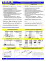
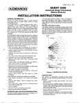
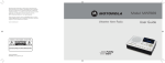
E.S.A.M. MANUALE D’USO / USER’S GUIDE ANALIZZATORE DI RETE MODULARE E2002 MODULAR NETWORK ANALYZER L’analizzatore di rete E2002 interamente progettato e sviluppato da ESAM è costruito per soddisfare tutte le moderne esigenze di misura e controllo dei parametri elettrici di una rete trifase e monofase. L’adozione di un microprocessore di ultima generazione, di un circuito di misura di nuova concezione con cambio portata automatico (8 portate per tensione, 8 portate per corrente), l’accurato dimensionamento di ogni componente e la taratura con strumenti certificati SIT garantiscono la massima precisione ed affidabilità in ogni condizione di utilizzo. The Network analyzer E2002 designed and developed wholly by ESAM is built to comply with all the modern requirements of measure and control of electrical parameters in single-phase and three-phase networks. Adoption of the latest generation microprocessors, of a new measuring circuit with auto-range, the careful choice of every component ( UL recognized printed circuits ) and the calibration with EAL.SIT certificated devices, provide the highest precision and reliability in every condition of use. L’impiego dell’analizzatore E2002 permette comunque di ottenere i seguenti vantaggi: semplificazione del cablaggio (un solo strumento per tutte le grandezze da misurare: acquisizioni contemporanee RMS di tensioni, correnti, cosϕ, potenze, energie, distorsioni armoniche …) ed elevata precisione (classe 0,5) configurazione in campo dei rapporti TA e TV per una lettura diretta dei valori (unità di misura automatiche) un unico apparecchio per tutte le inserzioni: monofase, trifase a 2 TA (ARON), trifase a 3 TA cambio pagina automatico programmabile media valori letti per “stabilizzare” la visualizzazione misura energia attiva e reattiva con 2 uscite ad impulsi programmabili per acquisizioni remote memorizzazione potenze medie e medie max. nel quarto d’ora supervisione e controllo con 2 allarmi configurabili su tutti i valori misurati e calcolati (ved. tabella seguente) controllo temperatura / senso ciclico fasi / contaore interfaccia seriale isolata RS485 per dialogo con PC / PLC (programmazioni e lettura parametri) con 3 protocolli di comunicazione seriale (ved. relativi manuali): ESAM, Modbus RTU (fino a 19200 baud, letture multiple, “blocco virtuale” …), N2BUS (Metasys - Johnson Controls) esecuzione modulare a 6 moduli DIN con tastiera a membrana antigraffio e sportellino frontale piombabile codice segreto di accesso The use of the analyzer E2002 allows to obtain several advantages: simplification of wire assembly (a single meter for all the variables to be measured: simultaneous acquisition of: RMS voltages, RMS currents, frequency, cosϕ, powers, energies, THD..) and high accuracy (0,5%) in field configuration of CT and VT ratios for direct values reading (automatic selection engineering units) a single device for all type of connection: single-phase, three phase with 2 CT (ARON), three-phase with 3 CT automatic programmable page change averaging with selectable response time measure of active and reactive energy with 2 programmable pulse outputs for remote acquisition storage of max. average powers every 15 minutes 2 user configurable alarms. Nearly all measured/calculated values can be selected as alarm source (see table below) temperature / phase sequence / hour counter RS485 insulated serial interface for connection to PC/PLC (programming and reading) with 3 serial communication protocols (see manuals): ESAM, Modbus RTU (up to 19200 baud, multiple reading, “virtual block” …), N2BUS (Metasys - Johnson Controls) modular execution (6 DIN modules) with scratch-resistant membrane touch switches and protective panel which may be sealed secret access code Unità di misura Measured units Grandezze Variables Tensioni di fase / Phase Voltages Tensioni concatenate / Linked Voltages Tensione concatenata media / Linked average Voltage Correnti / Currents Corrente media / Average Current Potenze attive / Active Powers Potenza attiva totale / Total Active Power Potenze reattive / Reactive Powers Potenza reattiva totale / Total Reactive Power Potenze apparenti / Apparent Powers Potenza apparente totale / Total Apparent Power Cosϕ di fase / Phase Cosϕ Cosϕ totale / Total Cosϕ Frequenza / Frequency Energia attiva positiva e negativa / + and - Active Energy Energia reattiva positiva e negativa / + and - Reactive Energy Potenze medie (es. 15 min.) / Average Powers (ex. 15 min.) Potenze medie max. / Peaks of Average Powers Memorizzazione 4 valori massimi / 4 Peak values storage Contaore / Hour-meter Temperatura (sonda interna) / Temperature (built in probe) Senso ciclico delle fasi / Phase sequence Distorsione armonica / Total harmonic distortion ) E2002 V1N V2N V3N V12 V23 V31 Vtm I1 I2 I3 Itm P1 P2 P3 Ptot Q1 Q2 Q3 Qtot S1 S2 S3 Stot PF1 PF2 PF3 PF Frequency Wh(+) Wh(-) VARh(+) VARh(-) Pm(+) Pm(-) Qm(+) Qm(-) Pm(+) Pm(-) Qm(+) Qm(-) Peak 1…2 …3…4 Hour Meter Temperature V. Phase Sequence Thd V1-V2-V3 Thd I1-I2-I3 [email protected] www.esam.biz Valori Valori misurati calcolati Measured Calculated values values Allarmi Alarms [V] [V] [V] [A] [A] [W] [W] [VAR] [VAR] [VA] [VA] [φ] [φ] [Hz] [Wh] [VARh] [W] [VAR] [W] [VAR] […] pk [hh.mm.ss] [°C ] [%] page 1 - 16 rev. 3.9 1011 E.S.A.M. MANUALE D’USO / USER’S GUIDE TECHNICAL DATA DATI TECNICI display: LCD retro illuminato ad alto contrasto, 2 righe x 16 caratteri (altezza 6 mm. circa) tensione d’ingresso: 15 … 300V (monofase), 30 … 500V (trifase) corrente d’ingresso: 0,05 … 6A corrente primaria massima impostabile : 99999A tensione primaria massima impostabile: 999999V fattore di cresta per tensione e corrente: 2 tempo di media valori visualizzati da 1 a 5 secondi misura temperatura quadro elettrico con sonda interna: risoluzione 1°C, ±1 digit contaore con base tempi quarzata: 6 cifre con risoluzione 1 sec. (risoluzione massima 999999.99.99 hh.mm.ss) classe di precisione per tensione, corrente e potenza attiva: ± 0,5% (± 1 digit), classe di precisione per potenza reattiva: ± 1% (± 1 digit) mantenimento valori energie, contaore e picchi in assenza di alimentazione: 2 mesi 2 uscite configurabili come: - impulsi per energie (durata impulso uscita: 1 - 255 msec) - allarmi (set-point, tipo allarme, isteresi, tempo di ritardo e tempo di autoripristino programmabili; es. di utilizzo: relè di mancanza fase con controllo tensione sulle 3 fasi, controllo carichi con autoripristino, …) portata transistor NPN uscita 1 & 2: 50V, 100mA (Mors. [12] Coll. 1 [13] Emitter 1 [14] Coll. 2 [15] Emitter 2). Esecuzione standard portata contatti relè statici uscita 1 & 2: 200V, 50mA (Mors. [12] C1 [13] NO1 [14] C2 [15] NO2 ). N.B. l’opzione relè statici va richiesta alimentazione ausiliaria: 115V-230V ± 15% 50/60Hz oppure in opzione: autoalimentato, 24Vca, 100Vca, 400Vca - consumo ≤ 4VA alimentazione ausiliaria opzionale: 12Vcc, 24Vcc, 48Vcc, 110Vcc, 220Vcc ± 10% (Morsetti [16] - e [18] +) - consumo ≤ 4W interfaccia seriale isolata RS485: per specifiche ved. relativi manuali mascherina per montaggio fronte quadro (a richiesta) high contrast LCD display with backlight: 2 lines x 16 characters (height about 6 mm.) input voltage: 15 … 300V (single-phase), 30 … 500V (three-phase) input current: 0,05 … 6A max. programmable value for primary current: 99999A max. programmable value for primary voltage:999999V voltage and current crest factor: 2 averaging time interval from 1 to 5 seconds measure of the temperature with built in probe: accuracy 1°C, ±1 digit hour-meter with crystal controlled time base: 6 digits with a resolution of 1 second (max resolution 999999.99.99 hh.mm.ss) active power, voltage and current accuracy: ± 0,5% (± 1 digit), reactive power accuracy: ± 1% (± 1 digit) data retention in case of lack of power supply: energies, hour-meter, peaks: 2 months 2 configurable outputs: - pulses for energy (output pulse duration: 1 … 255msec) - alarms (selectable on most measured and calculated values with hysteresis, programmable time-delay and self-resetting; using ex.: load self-resetting control, …) output NPN transistors 1 & 2 rating: 50V, 100mA (Pin. [12] Coll. 1 [13] Emitter 1 [14] Coll. 2 [15] Emitter 2). Standard execution output solid state relays 1 & 2 contacts rating: 200V, 50mA (Pin. [12] C1 [13] NO1 [14] C2 [15] NO2 ).This is an option available on request auxiliary power: 115-230V ± 15% 50/60Hz or as option: self-powered or 24V or 100V or 400V (to be specified) - consumption ≤ 4VA optional auxiliary power: 12Vdc or 24Vdc or 48Vdc or 110Vdc or 220Vdc (to be specified) ± 10% (Pin. [16] - [18] +) consumption ≤ 4W RS485 serial insulated output: commands listed on technical manual adapter for front panel mounting (on request). SCHEMI D’INSERZIONE / WIRING DIAGRAMS Circuito trifase a 4 fili (3 TA) Three-phase 4 wires circuit (3 CT) Circuito trifase a 3 fili (2 TA, inserzione ARON) Three-phase 3 wires circuit (2 CT, ARON insertion) Circuito monofase / Single-phase circuit Inserzioni con TV / VT Insertions DIMENSIONI D’INGOMBRO OVERALL DIMENSIONS ) E2002 MASCHERINA PER MONTAGGIO FRONTE QUADRO E FORATURA ADAPTER FOR FRONT PANEL MOUNTING AND CUTOUT [email protected] www.esam.biz page 2 - 16 rev. 3.9 1011 E.S.A.M. MANUALE D’USO / USER’S GUIDE NORME DI RIFERIMENTO / REFERENCE STANDARDS Caratteristiche di sicurezza secondo le norme / Safety characteristics complying with: EN 61010-1 (CEI 66-5) Compatibilità elettromagnetica secondo le norme / Electromagnetic compatibility complying with: EN 61326 (CEI 65-97) CONDIZIONI AMBIENTALI / ENVIRONMENTAL CONDITIONS Temperatura di impiego / Operating temperature: -10°C ... +55°C Temperatura di immagazzinamento / Storage temperature: -30°C ... +70°C Temperatura di riferimento / Reference temperature: +20°C Coefficiente di temperatura / Temperature coefficient: ±0,01%/°C Umidità relativa dell’ambiente 85% senza condensazione con 35°C di temperatura per massimo 60 gg./anno; l’umidità media annua non deve superare il 65% (DIN40040) Environment rh 85% not condensing at 35°C for max. 60 day/year; the yearly average humidity must not exceed 65% (DIN40040). ISOLAMENTO GALVANICO / GALVANIC INSULATION Isolamento tra / Insulation between: • ingressi voltmetrici ed amperometrici /Voltmetric and amperometric inputs • ingressi voltmetrici ed uscita seriale / Voltmetric input and serial output • ingressi voltmetrici ed uscita impulsi/allarme / Voltmetric input and pulse/alarm outputs • ingressi amperometrici ed uscita seriale / Amperometric input and serial output • ingressi amperometrici ed uscita impulsi/allarme / Amperometric input and pulse/alarm outputs • ingressi ed alimentazione ausiliaria / Input and auxiliary power • uscita seriale ed alimentazione ausiliaria / serial output and auxiliary power • uscita impulsi/allarme e alimentazione ausiliaria / pulse/alarm outputs and auxiliary power 2KV/60 sec. 50Hz 2KV/60 sec. 50Hz 2KV/60 sec. 50Hz 2KV/60 sec. 50Hz 2KV/60 sec. 50Hz 2KV/60 sec. 50Hz 2KV/60 sec. 50Hz 2KV/60 sec. 50Hz FUNZIONE DEI PULSANTI / FUNCTION OF THE BUTTONS - DURANTE LA PROGRAMMAZIONE / IN PROGRAM MENU Va al parametro successivo da impostare / Go to next parameter to be set Va al parametro precedente da impostare / Go to previous parameter to be set CR P Esce dalla programmazione / Exit programming Da accesso alla modifica del parametro e premuto successivamente lo salva / Modify parameter - DURANTE IL NORMALE FUNZIONAMENTO / DURING NORMAL OPERATION Va alla pagina successiva / Go to next page Va alla pagina precedente / Go to previous page CR P Visualizza il numero di pagina e i parametri contenuti / Display the page number and description Premuto per 2 secondi abilita la programmazione / Keep it pressed for 2 seconds to enter program menu N.B. La programmazione si interrompe automaticamente se non viene premuto alcun tasto entro 1 minuto N.B. The programming automatically stops if no button is pressed within 1 minutes.. IMPOSTAZIONE GENERICA DI UN PARAMETRO / GENERIC SETTING OF A PARAMETER Premere “P” per cambiare il valore di un parametro. Se appare “select” nella parte bassa del display, selezionare tra I valori proposti con I tasti “ ” o “ ” quindi premere “P” per confermare. Se il parametro è un valore numerico la prima cifra inizia a lampeggiare. Il numero indicato dal cursore può essere cambiato premendo “ ” o “ ” per ottenere il valore desiderato (es. 1 2 3 4 5 6 7 8 9 0 1…). Impostata la prima cifra si sposta il cursore di un posto a sinistra con il tasto “CR” e si ripete la sequenza fino ad ottenere il valore voluto. Premere “P” per confermare il numero. Per USCIRE dalla programmazione premere il tasto “CR”. N.B. Se per viene impostato un valore inferiore o superiore ai limiti, indicati sul display in basso a sinistra, apparirà per circa 1 secondo la scritta (“ERROR!! ”)dopodiché lo strumento ripristinerà il valore precedentemente impostato. Press “P” to change the value of a parameter. If “select” appears in the lower part of the display, select from a list of choices using keys “ ” or “ ”,then press “P” to confirm. If the parameter has a numeric value, the first digit will start blinking. The number indicated by the cursor can be changed pressing “ ” or “ ”, to obtain the desired value ex. 1 2 3 4 5 6 7 8 9 0 1. Set the first digit, move the cursor one step left pressing “CR “ and repeat the sequence to obtain the desired value. Press “P” to confirm the number. If the entered value is lower or higher then the allowed limits, indicated on the lower area of the display, the message To EXIT press “CR” (“ERROR!!”) will be displayed for one second, then the device will display again the previously set value. ) www.esam.biz E2002 [email protected] page 3 - 16 rev. 3.9 1011 E.S.A.M. MANUALE D’USO / USER’S GUIDE ELENCO GRANDEZZE MISURATE / LIST OF THE MEASUREMENTS GRANDEZZA LABEL V1N V2N V3N I1 I2 I3 P1 P2 P3 Frequency V12 V23 V31 Vtm Itm Ptot S1 S2 S3 Stot PF1 PF2 PF3 PF Q1 Q2 Q3 Qtot Wh(+) Wh(-) VARh(+) VARh(-) W(+) W(-) VAR(+) VAR(-) Peak 1 Peak 2 Hour Meter Temperature V. Phase Sequence Alarm Alarm Peak 3 Peak 4 W(+) W(-) VAR(+) VAR(-) Thd V1 Thd V2 Thd V3 Thd I1 Thd I2 Thd I3 ) DESCRIZIONE DESCRIPTION Peak Peak Pulse Alarm Pulse Alarm Tensione fase 1 / Voltage Phase 1 Tensione fase 2 / Voltage Phase 2 Tensione fase 3 / Voltage Phase 3 Corrente fase 1 / Current Phase 1 Corrente fase 2 / Current Phase 2 Corrente fase 3 / Current Phase 3 Potenza Attiva fase 1 / Active Power Phase 1 Potenza Attiva fase 2 / Active Power Phase 2 Potenza Attiva fase 3 / Active Power Phase 3 Frequenza (misurata sulla tensione fase 1) / Frequency (measured on Phase 1) Tensione concatenata fase 1-2 / Linked Voltage Phase 1-2 Tensione concatenata fase 2-3 / Linked Voltage Phase 2-3 Tensione concatenata fase 3-1 / Linked Voltage Phase 3-1 Tensione concatenata media (V12+V23+V31)/3 / Average Voltage (V12+V23+V31)/3 Corrente media (I1+I2+I3)/3 / Average Current (I1+I2+I3)/3 Potenza Attiva totale (P1+P2+P3) / Total active power (P1+P2+P3) Potenza Apparente fase 1 / Apparent power Phase 1 Potenza Apparente fase 2 / Apparent power Phase 2 Potenza Apparente fase3 / Apparent power Phase 3 Potenza Apparente totale (√P²+Q²) / Total apparent power (√P²+Q²) Fattore di potenza fase 1 / Power factor Phase 1 Fattore di potenza fase 2 / Power factor Phase 2 Fattore di potenza fase 3 / Power factor Phase 3 Fattore di potenza del sistema trifase / The three-phase power factor Potenza Reattiva fase 1 / Reactive power Phase 1 Potenza Reattiva fase 2 / Reactive power Phase 2 Potenza Reattiva fase 3 / Reactive power Phase 3 Potenza Reattiva totale (Q1+Q2+Q3) / Total reactive power (Q1+Q2+Q3) Energia Attiva positiva totale / Total positive Active energy Energia Attiva negativa totale / Total negative Active energy Energia Reattiva positiva totale / Total positive Reactive energy Energia Reattiva negativa totale / Total negative Reactive energy Potenza Attiva positiva media nel quarto d’ora / Average positive Active power in 15 minutes Potenza Attiva negativa media nel quarto d’ora / Average negative Active power in 15 minutes Potenza Reattiva positiva media nel quarto d’ora / Average positive Reactive power in 15 min. Potenza Reattiva negativa media nel quarto d’ora / Average negative Reactive power in 15 min. Valore di picco 1 / Peak value 1 Valore di picco 2 / Peak value 2 Contaore / Hour meter Temperatura quadro (sonda interna) / Temperature (internal probe) Senso ciclico delle fasi / Phase sequence Stato allarme 1 / Output state 1 Stato allarme 2 / Output state 2 Valore di picco 3 / Peak value 3 Valore di picco 4 / Peak value 4 Potenza Attiva positiva massima nel quarto d’ora / Max positive Aactive power in 15 minutes Potenza Attiva negativa massima nel quarto d’ora / Max negative Active power in 15 minutes Potenza Reattiva positiva massima nel quarto d’ora / Max positive Reactive power in 15 min. Potenza Reattiva negativa massima nel quarto d’ora / Max negative Reactive power in 15 min. Distorsione armonica totale V1 (%) / Total harmonic distortion V1 (%) Distorsione armonica totale V2 (%) / Total harmonic distortion V2 (%) Distorsione armonica totaleV3 (%) / Total harmonic distortion V3 (%) Distorsione armonica totale I1 (%) / Total harmonic distortion I1 (%) Distorsione armonica totale I2 (%) / Total harmonic distortion I2 (%) Distorsione armonica totale I3 (%) / Total harmonic distortion I3 (%) E2002 [email protected] www.esam.biz page 4 - 16 rev. 3.9 1011 E.S.A.M. MANUALE D’USO / USER’S GUIDE ELENCO PAGINE VISUALIZZATE / LIST OF DISPLAYED PAGES GRANDEZZA LABEL DESCRIZIONE DESCRIPTION Codice Code Tensione concatenata media, Corrente media, Potenza Attiva totale, Fattore di potenza totale Vtm Itm Ptot PF Average line voltage, average current, total Active power, total power-factor Page: 1 Tensione, Corrente, Potenza Attiva, Fattore di potenza fase 1 V1 I1 P1 PF1 Voltage, Current, Active power, power-factor phase 1 Page: 2 Tensione, Corrente, Potenza Attiva, Fattore di potenza fase 2 V2 I2 P2 PF2 Voltage, Current, Active power, power-factor phase 2 Page: 3 Tensione, Corrente, Potenza Attiva, Fattore di potenza fase 3 V3 I3 P3 PF3 Voltage, Current, Active power, power-factor phase 3 Stot PF Qtot S1 P1 Q1 S2 P2 Q2 S3 P3 Q3 V12 V23 V31 V1N V2N V3N I1 I2 I3 P1 P2 P3 PF1 PF2 PF3 V1N Frequency Wh(+) VARh(+) Wh(-) VARh(-) Wh(+) Wh(-) VARh(+) VARh(-) Wh(+) Wh(-) VARh(+) VARh(-) Peak 1 Peak 2 Peak 3 Peak 4 Pm(+) last/max Pm(-) last/max Qm(+) last/max Qm(-) last/max Thd V1-V2-V3 Thd I1-I2-I3 Temperature Alarm HOUR METER Page: 4 Potenza Apparente , Potenza Reattiva , Fattore di potenza totali Apparent power, Reactive power, total power factor Potenza Apparente, Potenza Attiva, Potenza Reattiva della fase 1 Apparent power, Active power, Reactive power of the phase 1 Potenza Apparente, Potenza Attiva, Potenza Reattiva della fase 2 Apparent power, Active power, Reactive power of the phase 2 Potenza Apparente, Potenza Attiva, Potenza Reattiva della fase 3 Apparent power, Active power, Reactive power of the phase 3 Tensioni concatenate / Linked Voltage: Phase 1-2, Phase 2-3, Phase 3-1 Page: 5 Page: 6 Page: 7 Page: 8 Page: 9 Tensioni di fase / Phase 1 voltage, Phase 2 voltage, Phase 3 voltage Page: 10 Correnti / Phase 1 Current, Phase 2 current, Phase 3 current Page: 11 Potenze Attive / Active powers Page: 12 Fattori di potenza di fase / Phase power-factors Tensione della fase1, Frequenza misurata sulla fase 1 Voltage phase 1, frequency measured on phase 1 Energia Attiva positiva, Energia Reattiva positiva totali Total positive active energy, positive reactive energy Energia Attiva negativa, Energia Reattiva negativa totali Total negative active energy, negative reactive energy Energia Attiva positiva e negativa totali / Total positive and negative active energy Page: 13 Page: 14 Page: 15 Page: 16 Page: 17 Energia Reattiva positiva e negativa totali / Total positive and negative active energy Page: 18 Energia Attiva positiva totale / Total positive active energy Page: 19 Energia Attiva negativa totale / Total negative active energy Page: 20 Energia Reattiva positiva totale / Total positive reactive energy Page: 21 Energia Reattiva negativa totale / Total negative reactive energy Page: 22 Visualizzazione valore di picco 1 e valore di picco 2 / Peak 1, Peak 2 Page: 23 Visualizzazione valore di picco 3 e valore di picco 4 / Peak 3, Peak 4 Potenza Attiva media positiva integrata nel quarto d’ora e la massima Average / max. positive active power in 15 minutes Potenza Attiva media negativa integrata nel quarto d’ora e la massima Average / max. negative active power in 15 minutes Potenza Reattiva media positiva integrata nel quarto d’ora e la massima Average / max. positive reactive power in 15 minutes Potenza Reattiva media negativa integrata nel quarto d’ora e la massima Average / max. negative reactive power in 15 minutes Distorsione armonica V1, V2, V3 / Total harmonic distortion V1, V2, V3 Page: 24 Page: 25 Page: 26 Page: 27 Page: 28 Page: 29 Distorsione armonica I1, I2, I3 / Total harmonic distortion I1, I2, I3 Page: 30 Temperatura quadro / Temperature Page: 31 Controllo dello stato allarmi (ved. Nota 1) / Output state (see note 1) Page: 32 Ore di funzionamento / Hour meter Page: 33 V.Phase sequence Senso ciclico delle fasi / Phases sequence ) E2002 [email protected] Page: 34 www.esam.biz page 5 - 16 rev. 3.9 1011 E.S.A.M. MANUALE D’USO / USER’S GUIDE Nota 1 / Note 1 In questa pagina è possibile monitorare lo stato degli allarmi se abilitati, altrimenti comparirà la scritta DISABLED. La pagina visualizza la grandezza, il tipo di allarme e lo stato delle uscite ON OFF. I simboli delle grandezze è possibile ritrovarli nella tabella delle grandezze misurate, ad esclusione di quelli trifase, che verranno rappresentati aggiungendo un pedice x al simbolo generale. E’ possibile monitorare quando si è in allarme ma non è ancora trascorso il tempo di ritardo intervento (TDAL1,TDAL2), infatti durante tale tempo la scritta OFF lampeggia. E’ possibile monitorare quando non si è più in allarme ma non è ancora trascorso il tempo di autoripristino (TRAL1,TRAL2), infatti durante tale tempo la scritta ON lampeggia. Impostando un allarme di minima comparirà il simbolo “ ” ׀, ” ׀, a finestra “ ׀ di massima “ AL1 AL2 V1 Ix AL1 AL2 V2 Px ׀ ׀ ׀ ”׀. Esempi: This page shows the current status of alarms AL1 and AL2. For each alarm it shows the monitored variable, the alarm type and output status. Alarm type can be min “” ׀, max “ ”׀or window “׀ ”׀. Same monitored values can be selected as 3-phase: this applies to sets of phase values (e.g. P1-P2.P3,..). A 3-phase alarm is triggered when ANY value in the set is outside limits. It is possible to see when the alarm is changing state: -the word OFF will blink for all delay time. The alarm is on but the output state is off. -the word ON will blink for all auto-reset time. The alarm is off but the output state is on. Examples: Allarme 1 su V1 di min. OFF / Alarm 1 on V1 min. OFF Allarme 2 su Ix (I trifase) di max. ON / Alarm 2 on Ix (3phase) max. ON Lo stato ON è anche visibile sui 2 led rossi frontali./ ON status is displayed on 2 frontal led OFF ׀ON ׀ON ׀OFF Allarme 1 su V2 a finestra. ON / Alarm 1 on V2 window. ON Allarme 2 su Px (P trifase) a finestra OFF / Alarm 2 on Px (3phase) window OFF ACCENSIONE DELLO STRUMENTO / POWER ON THE DEVICE All’accensione, sullo strumento, comparirà per 2 sec. la scritta / At power on, a message like the following will be displayed for 2 sec.: Il numero “3.x” indica la versione del software, 9600 è il baud rate “N” (nessuna parità), “8” (bit in una word) e “1” stop bit. / The number “3.x” indicates the software version, 9600 is baud rate, “N” (parity), “8” (bit in one word) and “1” stop bit. E2002 v3.x WAIT 9600, N, 8, 1 PROGRAMMAZIONE / PROGRAMMING Premere il pulsante “P” per 2 secondi, comparirà la scritta lampeggiante “Program” e quindi premere “ ”. Se è stata impostata una password prima di entrare in programmazione verrà visualizzato il seguente messaggio (“ENTER PASSWORD...”) E’ sempre possible saltare l’impostazione premendo “ ”; uscire dalla programmazione con “CR”;cambiare il valore con “P”. (Ved. IMPOSTAZIONE GENERICA DI UN PARAMETRO). N.B. Nelle descrizioni successive i valori assunti dalle variabili sono quelli di default (ved. tabella VALORI DI DEFAULT). Press button “P” for 2 seconds (blinking “Program”) and then press “ ”. If a password was set , the following message (“ENTER PASSWORD...”) will be displayed to enter the programming. It is always possible to skip the setting pressing “ ”; to go out of program menu pressing “CR”, or change the value with “P” (see GENERIC SETTING OF A PARAMETER). N.B. In this guide following displayed values are the default values (ved. table DEFAFULT VALUES). Di default la password è 00000 che disabilita la protezione, quindi si accederà direttamente al menù. Una volta inserita l’eventuale password premere “P” per confermare. Input the personal password to get access to configuration data. Press “P” to confirm. Enter Password XXXXX - CORRENTE PRIMARIA DEL TA / PRIMARY CURRENT VALUE OF CT CTP = 00005 (1-99999A) Es. TA da 1500/5A, il valore da inserire è 1500. Nota con ingresso diretto 5A impostare 5). Ex. CT 1500/5A, the value to be input is 1500. Note: with direct input 5A set 5. - CORRENTE SECONDARIA DEL TA / SECONDARY CURRENT VALUE OF CT CTS = 5.00 (1.00-6.00A) Es. TA da 1500/5A, il valore da inserire è 5. Nota con ingresso diretto 5A impostare 5). Ex. CT 1500/5A, the value to be input is 5. Note: with direct input 5A set 5. - TENSIONE PRIMARIA DEL TV / PRIMARY VOLTAGE VALUE OF VT VTP = 000300 (10-999999V) ) Es. TV da 800/100V, il valore da inserire è 800. Nota con ingresso diretto 230V impostare 230). Ex. VT 800/100V, the value to be input is 800.Note: with direct input 230V set 230. E2002 [email protected] www.esam.biz page 6 - 16 rev. 3.9 1011 E.S.A.M. MANUALE D’USO / USER’S GUIDE - TENSIONE SECONDARIA DEL TV / SECONDARY VOLTAGE VALUE OF VT VTS = 300.0 (57.7-300.0V) Es. TV da 800/100V, il valore da inserire è 800. Nota con ingresso diretto 230V impostare 230). Ex. VT 800/100V, the value to be input is 800.Note: with direct input 230V set 230. - PAGINA DI VALORI VISUALIZZATA ALL’ACCENSIONE / PAGE DISPLAYED AT POWER ON Questo parametro deve sempre essere abilitato. Per scegliere la pagina desiderata ved. tabella ELENCO PAGINE VISUALIZZATE. / This parameter must always be different from zero. To choose the desired page, please refer to the table LIST OF THE DISPLAYED PAGES. PAG1 = 02 (1-34) - SECONDA PAGINA DI VALORI / SECOND PAGE DISPLAYED Selezione della seconda pagina visualizzata in sequenza, che rimarrà visualizzata per il valore di TPAG (ved. - TEMPO DI PAGINA). Per scegliere la pagina ved. tabella ELENCO PAGINE VISUALIZZATE. Se non si desidera visualizzare una seconda pagina impostare zero Selection of the second page displayed in sequence, if TPAG is not zero.(See - PAGE TIMING) To choose the desired page, please refer to the table LIST OF THE DISPLAYED PAGES. To select no page, set this parameter to zero. PAG2 = 00 (0-34) - TERZA PAGINA DI VALORI / THIRD PAGE DISPLAYED Selezione della terza pagina visualizzata in sequenza, che rimarrà visualizzata per il valore di TPAG (ved. - TEMPO DI PAGINA). Per scegliere la pagina ved. tabella ELENCO PAGINE VISUALIZZATE. Se non si desidera visualizzare una seconda pagina impostare zero Selection of the third page displayed in sequence, if TPAG is not zero.(See - PAGE TIMING) To choose the desired page, please refer to the table LIST OF THE DISPLAYED PAGES. To select no page, set this parameter to zero. PAG3 = 00 (0-34) - QUARTA PAGINA DI VALORI / FOURTH PAGE DISPLAYED Selezione della quarta pagina visualizzata in sequenza, che rimarrà visualizzata per il valore di TPAG (ved. - TEMPO DI PAGINA). Per scegliere la pagina ved. tabella ELENCO PAGINE VISUALIZZATE. Se non si desidera visualizzare una seconda pagina impostare zero Selection of the fourth page displayed in sequence, if TPAG is not zero.(See - PAGE TIMING) To chose the desired page, please refer to the table LIST OF THE DISPLAYED PAGES. To select no page, set this parameter to zero. PAG4 = 00 (0-34) - TEMPO DI PAGINA / PAGE TIMING Intervallo di tempo in secondi tra la visualizzazione delle pagine selezionate. Impostato a zero visualizza sempre PAG1. / Time interval, in seconds, after which the display is switched to the next selected page. Set this parameter to zero to display PAG1 forever. TPAG = 00 (0-99sec) - TEMPO DI MEDIA DEI VALORI / AVERAGING TIME INTERVAL E’ il tempo in secondi durante il quale si fa la media delle misure acquisite. Può assumere valori compresi tra 1 e 5 secondi. / Approximate time interval for acquisition of measurements. Averaging is actually taken over a given number of power line cycles. AVG = 1 (1-5sec) - CODICE SEGRETO / PASSWORD Se questo parametro viene impostato, l’accesso al menu di programmazione sarà protetto da password. L’utente dovrà inserire la password per entrare in programmazione. Se non si vuole abilitare la protezione da password impostare 00000. If this parameter is set to a value different from zero, access to program menu will be password protected. The user has to enter the set value as a password to get access to program menu. Set this parameter to zero to disable password protection. PASS = 00000 (0-99999) - MISURA DI PICCO 1 / MEASURE FOR PEAK VALUE 1 Seleziona la grandezza misurata della quale vogliamo memorizzare il massimo valore. Ved. ELENCO GRANDEZZE MISURATE. Valore di default: V1N / Selection of measurement to be monitored for peak detection. See LIST OF THE MEASUREMENTS Default value: V1N ChPk1 = V1N - MISURA DI PICCO 2 / MEASURE FOR PEAK VALUE 2 Seleziona la grandezza misurata della quale vogliamo memorizzare il massimo valore. Ved. ELENCO GRANDEZZE MISURATE. Valore di default: V1N / Selection of measurement to be monitored for peak detection. See LIST OF THE MEASUREMENTS Default value: V1N ChPk2 = V1N ) E2002 [email protected] www.esam.biz page 7 - 16 rev. 3.9 1011 E.S.A.M. MANUALE D’USO / USER’S GUIDE - MISURA DI PICCO 3 / MEASURE FOR PEAK VALUE 3 Seleziona la grandezza misurata della quale vogliamo memorizzare il massimo valore. Ved. ELENCO GRANDEZZE MISURATE. Valore di default: V1N / Selection of measurement to be monitored for peak detection. See LIST OF THE MEASUREMENTS Default value: V1N ChPk3 = V1N - MISURA DI PICCO 4 / MEASURE FOR PEAK VALUE 4 Seleziona la grandezza misurata della quale vogliamo memorizzare il massimo valore. Ved. ELENCO GRANDEZZE MISURATE. Valore di default: V1N / Selection of measurement to be monitored for peak detection. See LIST OF THE MEASUREMENTS Default value: V1N ChPk4 = V1N - USCITA 1 (ALLARME O IMPULSI) / OUTPUT 1 (ALARM OR PULSE) Definisce la funzione dell’uscita 1.Le possibilità sono: Alarm (uscita 1 allarme) Pulse (uscita impulsi) e None (uscita disabilitata). Scegliendo Alarm o Pulse verranno chiesti altri parametri (comparsi in coda a Out1) per impostare correttamente la funzione prescelta. Out1 = none Es: Impostando Out1 = Alarm e premendo “P”, si sceglie la funzione allarme. Per il corretto funzionamento si dovranno inserire altri parametri che verranno proposti premendo il tasto “ ”. In ordine TyAl1, ChAl1, Al1, HyAl1, TdAl1, TrAl1. Impostando Out1 = Pulse e premendo “P”, si sceglierà la funzione uscita impulsi. Per il corretto funzionamento si dovranno inserire altri parametri che verranno proposti premendo il tasto “ ”. In ordine : ChPO1, WPO1, TPO1. Selection of output function for output channel 1.Available choices are: Alarm - Pulse - None If the choice is Alarm the following steps of the program menu allow the detailed configuration of the alarm function: TyAl1, ChAl1, Al1, HyAl1, TdAl1, TrAl1. If the choice is Pulse the following steps of the program menu allow the detailed configuration of the Pulse function: ChPO1, WPO1, TPO1. I SEGUENTI PASSAGGI TyAl1, ChAl1, Al1, HyAl1, TdAl1, TrAl1 SONO INCLUSI NEL MENU DI PROGRAMMAZIONE SOLO SE OUT1 = Alarm THE FOLLOWING STEPS TyAl1, ChAl1, Al1, HyAl1, TdAl1, TrAl1 ARE INCLUDE IN PROGRAMMED MENU ONLY IF OUT1 = Alarm - TIPO DI ALLARME 1 / ALARM 1 TYPE Stabilisce il tipo di soglia che si vuole utilizzare. Impostando: “Low” la soglia sarà di minima su una fase, “High” la soglia sarà di massima su una fase, “Window” la soglia sarà a finestra su una fase, “Low 3ph” l’allarme interverrà se almeno una delle tre fasi scenderà sotto la soglia impostata, “High 3ph” l’allarme interverrà se almeno una delle tre fasi salirà sopra la soglia impostata, “Win 3ph” l’allarme interverrà se almeno una delle tre fasi uscirà dalla soglia a finestra impostata, “Ph. Seq.” l’allarme sarà sul senso ciclico delle 3 fasi. NOTA: Se si imposta un allarme trifase su una grandezza che non lo è, verrà accettata la configurazione, ma l’allarme sarà considerato monofase. This function defines the type of limit value to be used. Set “Low” for a minimum limit; set “High” for maximum limit; set “Window” to have a window alarm, set “Low 3ph” minimum limit on 3 phases; set “High 3ph” to set a maximum limit value on 3 phases; set “Win 3ph” for window alarm on 3 phases. NOTE: 3ph alarm apply only to sets of 3 phase values (e.g. P1-P2-P3): a 3-phase alarm is triggered when any value in the set is outside limits. “Ph. Seq.” is a special case: the alarm is triggered if a phase is not present or the sequence is wrong TyAl1 = Low - MISURA DA UTILIZZARE PER ALLARME 1 / MEASURE FOR ALARM 1 Assegna la misura da monitorare sulla quale si vuole impostare un allarme. Ved. ELENCO GRANDEZZE MISURATE / Selection of the measurements to be monitored for alarm 1. See LIST OF THE MEASUREMENTS ChAl1 = V1N - SOGLIA DI ALLARME 1 / ALARM 1 THRESHOLD Inserisce il valore della soglia d’intervento sulla misura precedentemente scelta. L’unità di misura e ( ) dipende dalla grandezza da monitorare. / Threshold value for Low and High Alarms, centre of the window for window Alarms. Unit ( ) is function of measurements to be monitored. Al1 = 000 ( ) - ISTERESI DELL’ ALLARME 1 / ALARM 1 HYSTERESIS Serve ad impostare l’isteresi della soglia d’allarme. L’ unità di misura ( ) dipende dalla misura da monitorare. Es. Soglia impostata a 300V con un’isteresi di 15V. Se la soglia è di minima interverrà al di sotto di 300V e, per ripristinarsi dovrà salire a 315V (300V + 15V). Se la soglia è di massima HyAl1 = 000 ( ) interverrà al di sopra di 300V e, per ripristinarsi dovrà scendere a 285V (300V-15). Se la soglia è a finestra interverrà al di sotto di 285V (300– 15) e al di sopra di 315V (300 + 15V). Se non si vuole nessuna isteresi sul valore di soglia, basta impostare 0 Unit ( ) is function of measurements to be monitored. Example Threshold = 300V, Hysteresis = 15V - Alarm Type is “Low”, alarm is triggered when the voltage falls below 300V and is reset when it raises over 315V. - Alarm Type is “High”, alarm is triggered when the voltage goes over 300V and is reset when it gets back below 285V. - Alarm type is “Window”, hysteresis defines the window width: alarm is triggered when voltage is outside the window 285-315 (300 ± 15V). ) E2002 [email protected] www.esam.biz page 8 - 16 rev. 3.9 1011 E.S.A.M. MANUALE D’USO / USER’S GUIDE - RITARDO DI INTERVENTO DELL’ALLARME 1 / ALARM 1 DELAY E’ un tempo impostabile, che intercorre, tra il superamento della soglia d’allarme e l’effettiva eccitazione del relè. Se non si vuole nessun tempo di ritardo, impostare 0. If this parameter has a non-zero value, when the monitored variable exceeds the given limits the alarm output is generated after a TdAl1. This feature can be used to prevent false alarms: an alarm condition lasting less then TdAl1 will not generate an alarm output. TdAl1 = 000 (0-99sec) - TEMPO DI RIPRISTINO DELL’ALLARME 1 / ALARM 1 SELF-RESETTING TIME E’ un tempo impostabile, durante il quale, non si è più in stato di allarme ma il relè rimane eccitato. Se non si vuole nessun tempo di ritardo, impostare 0. The alarm output is kept active for a TrAl1 time interval after recovering from an alarm condition. TrAl1 = 000 (0-9999sec) I SEGUENTI PASSAGGI ChPO1, WPO1, TPO1, SONO INCLUSI NEL MENU DI PROGRAMMAZIONE SOLO SE OUT1 = Pulse THE FOLLOWING STEPS ChPO1, WPO1, TPO1, ARE INCLUDE IN PROGRAMMED MENU ONLY IF OUT1 = Pulse - MISURA DA CONVERTIRE IN IMPULSI SULL’USCITA 1 / MEASURE FOR PULSE OUTPUT 1 Assegna la grandezza da monitorare sulla quale si vuole impostare l’ uscita impulsi 1. Ved. ELENCO GRANDEZZE MISURATE. Selection of the measurement to be converted. See LIST OF THE MEASUREMENTS ChPO1 = Wh(+) - PESO IMPULSI USCITA 1 / PULSE WEIGHT FOR OUTPUT 1 Un impulso viene generato quando il valore misurato si incrementa del peso impostato. Per spegnere l’ uscita impostare zero. ( ) Ved. sopra. / A pulse is generated whenever the selected measurement increases by this amount. To switch off the output channel 1, set 0. ( ) see above. WPO1 = 00.000 ( ) - DURATA IMPULSI USCITA 1 / PULSE DURATION FOR OUTPUT 1 Questo valore deve essere inferiore del 50% dell’intervallo di tempo tra gli impulsi. Impulsi sovrapposti non possono essere contati. / This value should be less than 50% of the time interval between pulses Overlapping pulse cannot be counted TPO1 = 100 (10-255ms) - USCITA 2 (ALLARME O IMPULSI) / OUTPUT 2 (ALARM OR PULSE) Definisce la funzione dell’uscita 2.Le possibilità sono: Alarm (uscita 2 allarme) Pulse (uscita impulsi) e None (uscita disabilitata). Scegliendo Alarm o Pulse verranno chiesti altri parametri (comparsi in coda a Out1) per impostare correttamente la funzione prescelta. Out2 = none Es: Impostando Out2 = Alarm e premendo “P”, si sceglie la funzione allarme. Per il corretto funzionamento si dovranno inserire altri parametri che verranno proposti premendo il tasto “ ”. In ordine TyAl2, ChAl2, Al2, HyAl2, TdAl2, TrAl2. Impostando Out2 = Pulse e premendo “P”, si sceglierà la funzione uscita impulsi. Per il corretto funzionamento si dovranno inserire altri parametri che verranno proposti premendo il tasto “ ”. In ordine : ChPO2, WPO2, TPO2. Selection of output function for output channel 2.Available choices are: Alarm - Pulse - None If the choice is Alarm the following steps of the program menu allow the detailed configuration of the alarm function: TyAl2, ChAl2, Al2, HyAl2, TdAl2, TrAl2. If the choice is Pulse the following steps of the program menu allow the detailed configuration of the Pulse function: ChPO2, WPO2, TPO2. I SEGUENTI PASSAGGI TyAl2, ChAl2, Al2, HyAl2, TdAl2, TrAl2 SONO INCLUSI NEL MENU DI PROGRAMMAZIONE SOLO SE OUT2 = Alarm THE FOLLOWING STEPS TyAl2, ChAl2, Al2, HyAl2, TdAl2, TrAl2 ARE INCLUDE IN PROGRAMMED MENU ONLY IF OUT2 = Alarm - TIPO DI ALLARME 2 / ALARM 2 TYPE Stabilisce il tipo di soglia che si vuole utilizzare. Impostando: “Low” la soglia sarà di minima su una fase, “High” la soglia sarà di massima su una fase, “Window” la soglia sarà a finestra su una fase, “Low 3ph” l’allarme interverrà se almeno una delle tre fasi scenderà sotto la soglia impostata, “High 3ph” l’allarme interverrà se almeno una delle tre fasi salirà sopra la soglia impostata, “Win 3ph” l’allarme interverrà se almeno una delle tre fasi uscirà dalla soglia a finestra impostata, “Ph. Seq.” l’allarme sarà sul senso ciclico delle 3 fasi. NOTA: Se si imposta un allarme trifase su una grandezza che non lo è, verrà accettata la configurazione, ma l’allarme sarà considerato monofase. This function defines the type of limit value to be used. Set “Low” for a minimum limit; set “High” for maximum limit; set “Window” to have a window alarm, set “Low 3ph” minimum limit on 3 phases; set “High 3ph” to set a maximum limit value on 3 phases; set “Win 3ph” for window alarm on 3 phases. NOTE: 3ph alarm apply only to sets of 3 phase values (e.g. P1-P2-P3): a 3-phase alarm is triggered when any value in the set is outside limits. “Ph. Seq.” is a special case: the alarm is triggered if a phase is not present or the sequence is wrong TyAl2 = Low ) E2002 [email protected] www.esam.biz page 9 - 16 rev. 3.9 1011 E.S.A.M. MANUALE D’USO / USER’S GUIDE - MISURA DA UTILIZZARE PER ALLARME 2 / MEASURE FOR ALARM 2 Assegna la misura da monitorare sulla quale si vuole impostare un allarme. Ved. ELENCO GRANDEZZE MISURATE / Selection of the measurements to be monitored for alarm 2. See LIST OF THE MEASUREMENTS ChAl2 = V1N - SOGLIA DI ALLARME 2 / ALARM 2 THRESHOLD Inserisce il valore della soglia d’intervento sulla misura precedentemente scelta. L’unità di misura e ( ) dipende dalla grandezza da monitorare. / Threshold value for Low and High Alarms, centre of the window for window Alarms. Unit ( ) is function of measurements to be monitored. Al2 = 000 ( ) - ISTERESI DELL’ ALLARME 2 / ALARM 2 HYSTERESIS Serve ad impostare l’isteresi della soglia d’allarme. L’ unità di misura ( ) dipende dalla misura da monitorare. Es. Soglia impostata a 300V con un’isteresi di 15V. Se la soglia è di minima interverrà al di sotto di 300V e, per ripristinarsi dovrà salire a 315V (300V + 15V). Se la soglia è di massima HyAl2 = 000 ( ) interverrà al di sopra di 300V e, per ripristinarsi dovrà scendere a 285V (300V-15). Se la soglia è a finestra interverrà al di sotto di 285V (300– 15) e al di sopra di 315V (300 + 15V). Se non si vuole nessuna isteresi sul valore di soglia, basta impostare 0 Unit ( ) is function of measurements to be monitored. Example Threshold = 300V, Hysteresis = 15V - Alarm Type is “Low”, alarm is triggered when the voltage falls below 300V and is reset when it raises over 315V. - Alarm Type is “High”, alarm is triggered when the voltage goes over 300V and is reset when it gets back below 285V. - Alarm type is “Window”, hysteresis defines the window width: alarm is triggered when voltage is outside the window 285-315 (300 ± 15V). - RITARDO DI INTERVENTO DELL’ALLARME 2 / ALARM 2 DELAY E’ un tempo impostabile, che intercorre, tra il superamento della soglia d’allarme e l’effettiva eccitazione del relè. Se non si vuole nessun tempo di ritardo, impostare 0. If this parameter has a non-zero value, when the monitored variable exceeds the given limits the alarm output is generated after a TdAl2. This feature can be used to prevent false alarms: an alarm condition lasting less then TdAl2 will not generate an alarm output. TdAl2 = 000 (0-99sec) - TEMPO DI RIPRISTINO DELL’ALLARME 2 / ALARM 2 SELF-RESETTING TIME E’ un tempo impostabile, durante il quale, non si è più in stato di allarme ma il relè rimane eccitato. Se non si vuole nessun tempo di ritardo, impostare 0. The alarm output is kept active for a TrAl2 time interval after recovering from an alarm condition. TrAl2 = 000 (0-9999sec) I SEGUENTI PASSAGGI ChPO2, WPO2, TPO2, SONO INCLUSI NEL MENU DI PROGRAMMAZIONE SOLO SE OUT2 = Pulse THE FOLLOWING STEPS ChPO2, WPO2, TPO2, ARE INCLUDE IN PROGRAMMED MENU ONLY IF OUT2 = Pulse - MISURA DA CONVERTIRE IN IMPULSI SULL’USCITA 2 / MEASURE FOR PULSE OUTPUT 2 Assegna la grandezza da monitorare sulla quale si vuole impostare l’ uscita impulsi 2. Ved. ELENCO GRANDEZZE MISURATE. Selection of the measurement to be converted. See LIST OF THE MEASUREMENTS ChPO2 = Wh(+) - PESO IMPULSI USCITA 2 / PULSE WEIGHT FOR OUTPUT 2 Un impulso viene generato quando il valore misurato si incrementa del peso impostato. Per spegnere l’ uscita impostare zero. ( ) Ved. sopra. / A pulse is generated whenever the selected measurement increases by this amount. To switch off the output channel 1, set 0. ( ) see above. WPO2 = 00.000 ( ) - DURATA IMPULSI USCITA 2 / PULSE DURATION FOR OUTPUT 2 Questo valore deve essere inferiore del 50% dell’intervallo di tempo tra gli impulsi. Impulsi sovrapposti non possono essere contati. / This value should be less than 50% of the time interval between pulses Overlapping pulse cannot be counted TPO2 = 100 (10-255ms) - PROTOCOLLO DA UTILIZZARE PER LA COMUNICAZIONE SERIALE / COMMUNICATION PROTOCOL Scelte disponibili: - Esam -ModBus (RTU) - Modbus M - N2JC (N2BUS-Metasys - Johnson Controls) / Available choices: -Esam - ModBus (RTU) -Modbus M - N2JC (N2BUS-Metasys Johnson Controls) PROT = Modbus - NUMERO TERMINALE PER COMUNICAZIONE SERIALE / STATION ADDRESS NUMT = 001 (1-255) ) Assegna all’analizzatore di rete un numero di riconoscimento da 1 a 255. This assigns the network analyser an identification number from 1 to 255. E2002 [email protected] www.esam.biz page 10 - 16 rev. 3.9 1011 E.S.A.M. MANUALE D’USO / USER’S GUIDE - VELOCITÀ DI COMUNICAZIONE / COMMUNICATION RATE BAUD = 9600 Si possono impostare le seguenti velocità: 1200,2400,4800,9600, 19200. The following rates can be selected: 1200,2400,4800,9600,19200. - MINIMO RITARDO ALLA RISPOSTA / MIN. DELAY BEFORE REPLY È il ritardo minimo di risposta a una richiesta seriale. Viene spesso utilizzato per adattare PC di diverse velocità al SW in uso. / This is the minimum delay between query and reply for serial communication. The default is 5 ms and is normally adequate. XDEL = 005 (0-255ms) - FORMATO FLOATING POINT (SOLO MODBUS) / FLOATING POINT FORMAT (MODBUS PROTOCOL ONLY) Un valore floating point è lungo 32 bit ed è inviato da modbus come 2 word (di 16 bits ognuna). Non c’è un accordo standard riguardo quale word debba essere inviata per prima. Con questo parametro si può scegliere l’ordine di invio affinché il Modbus master le riconosca. A floating point value is 32 bits long and is sent by Modbus as 2 words (16 bits each). There is no standard agreement about which word has to be sent first, so set this parameter to have them sent in the order that your master Modbus equipment understands. SWFP = no swap - TIPO DI CONNESSIONE TRIFASE / INPUT 3 PHASE CONNECTION Questa impostazione definisce che tipo di sistema di misura si utilizzerà. Selezionare “2CT Aron” per circuito trifase a 3 fili, (2 TA, inserzione ARON ) oppure “3CT” per circuito trifase a 4 fili (3 TA) o monofase. This setting defines which kind of input connection is used. Select “2CT Aron” to use a three phase circuit with 3 wires (with 2 CT - ARON). Select “3CT ” to use a 4-wires three-phase circuit (with 3 CT) or a single-phase circuit. InCfg = 3CT - TEMPO PER IL CALCOLO DELLA POTENZA MEDIA / TIME SETTING TO CALCULATE THE AVERAGE POWER È il tempo, durante il quale, viene effettuato il calcolo della potenza media, e confrontata con la massima memorizzata (es. 15 minuti) This is the time after which a calculation of the average power is performed. E.g. 15 minutes. TPm = 15 (1-99min) - AZZERAMENTO DELL’ENERGIE / ENERGY RESET Permette di azzerare i valori di energia accumulati. Premere “P”, successivamente verrà richiesto di premere “P” per azzerare o “CR” per annullare l’operazione. / Reset energy values Wh(+), Wh(-), VARh(+), VARh(-). Press “P”, then “P” again to confirm or “CR” to cancel. ResEn ? - AZZERAMENTO DEI VALORI DI PICCO / PEAK VALUES RESET Permette di azzerare i valori di picco selezionati. Premere “P”, successivamente verrà richiesto di premere “P” per azzerare o “CR” per annullare l’operazione. Reset peak values Peak1..4. Press “P”, then “P” again to confirm or “CR” to cancel. ResPk ? - AZZERAMENTO DELLE MASSIME POTENZE MEDIE / RESET OF MAXIMUM AVERAGE POWER Permette di azzerare i valori di picco delle potenze medie. Premere “P”, successivamente verrà richiesto di premere “P” per azzerare o “CR” per annullare l’operazione. / Reset average power values Pm(+), Pm(-), Qm(+), Qm(-). Press “P”, then “P” again to confirm or “CR” to cancel. ResPm ? - AZZERAMENTO DELLE POTENZE MEDIE / RESET OF AVERAGE POWER Permette di ricominciare un nuovo ciclo di integrazione di durata TPm. Premere “P“, successivamente verrà richiesto di premere “P” per azzerare o “CR” per annullare l’operazione. Restart a new averaging period TPm. Press “P”, then “P” again to confirm or “CR” to cancel. SynPm ? - AZZERAMENTO DEL CONTAORE / RESET OF HOUR COUNTER Azzera il contaore. Premere “P“, successivamente verrà richiesto di premere “P” per azzerare o “CR” per annullare l’operazione /. Reset hour counter. Press “P”, then “P” again to confirm or “CR” to cancel. ResH ? ) E2002 [email protected] www.esam.biz page 11 - 16 rev. 3.9 1011 E.S.A.M. MANUALE D’USO / USER’S GUIDE - CARICAMENTO DEI PARAMETRI DI DEFAULT / LOADING OF DEFAULT PARAMETERS Carica i valori di fabbrica predefiniti per ciascun parametro esclusa la password (ved. VALORI DI DEFAULT). Premere “P“, successivamente verrà richiesto di premere “P” per azzerare o “CR” per annullare l’operazione. N.B Questo parametro azzera i valori collegati a quelli di default, le energie totalizzate e i picchi memorizzati. Viene inoltre azzerato il contaore. Si può saltare l’impostazione premendo il tasto “ ”; uscire dalla programmazione premendo “CR”. Load default factory values for all parameters except password (see DEAFULT VALUES). Press “P”, then “P” again to confirm or “CR” to cancel. WARNING: this command resets all accumulated values, that is energies, peaks, max average, powers and hour counter. It is possible to skip the setting pressing “ ” or to go out of program menu pressing “CR” LDEF ? FINE DELLA PROGRAMMAZIONE / END OF PROGRAMMING VALORI DI DEFAULT / DEFAULT VALUES PARAMETRI VALORI PARAMETERS VALUES CTP CTS VTP VTS PAG1 PAG2 PAG3 PAG4 TPAG AVG PASS ChPk1 ChPk2 ChPk3 ChPk4 OUT1 OUT2 ChAl1 ChAl2 TyAl1 TyAl2 Al1 Al2 HyAl1 HyAl2 TdAl1 TdAl2 TrAl1 TrAl2 ChPO1 ChPO2 WPO1 WPO2 TPO1 TPO2 PROT NUMT BAUD XDEL SWFP INCFG TPm ( 1-99999A 1-6.00A 300-999999V 57.7-300V 1-34 0-34 0-34 0-34 1-99sec 1-5 00000=off 000 000 0-99sec 0-99sec 0-9999sec 0-9999sec 00.000=Off 00.000=Off 10-255ms 10-255ms 1-255 0-255ms 1-99min DESCRIZIONE DESCRIPTION DEFAULT DEFAULT Valore della corrente primaria del TA / CT primary current value Valore della corrente secondaria del TA / CT secondary current value Valore della tensione primaria del TV / VT primary voltage value Valore della tensione secondaria del TV / VT secondary voltage value Pagina di valori all’accensione / Page displayed at power on Seconda pagina di valori / Second page displayed Terza pagina di valori / Third page displayed Quarta pagina di valori / Fourth page displayed Tempo di pagina / Page time Numero medie / Averaging time interval Password ( ) / Password ( ) Misura di picco 1 / Peak 1: measure to be monitored Misura di picco 2 / Peak 2: measure to be monitored Misura di picco 3 / Peak 3: measure to be monitored Misura di picco 4 / Peak 4: measure to be monitored Tipo uscita 1 / Output 1 type Tipo uscita 2 / Output 2 Misura associata all’ allarme 1 / Alarm 1: measure to be monitored Misura associata all’ allarme 2 / Alarm 2: measure to be monitored Tipo di allarme 1 / Alarm 1 type Tipo di allarme 2 / Alarm 2 type Soglia allarme 1 / Alarm 1 threshold Soglia allarme 2 / Alarm 2 threshold Isteresi allarme 1 / Alarm 1 hysteresis Isteresi allarme 2 / Alarm 2 hysteresis Ritardo di intervento allarme 1 / Alarm 1 activation delay Ritardo di intervento allarme 2 / Alarm 2 activation delay Tempo di autoripristino allarme 1 / Alarm 1 auto-reset time Tempo di autoripristino allarme 2 Alarm 1 auto-reset time Misura convertita in impulsi, uscita 1 / Pulse output 1: measure to be converted Misura convertita in impulsi, uscita 2 / Pulse output 2: measure to be converted Peso dell’impulso 1 / Pulse 1 weight Peso dell’impulso 2 / Pulse 2 weight Durata dell’impulso 1 / Pulse 1 duration Durata dell’impulso 2 / Pulse 2 duration Protocollo di comunicazione / Communication protocol Numero di terminale / Station address Velocità seriale / Baud rate Minimo tempo di ritardo alla risposta / Min reply delay time 32 bit Floating point swap / 32 bit Floating point swap Tipo di connessione trifase / 3-phase connection Tempo di calcolo della potenza media / Calculation time for average power 00005 5.00 000300 300.0 02 00 00 00 00 1 00000 V1N V1N V1N V1N none none V1N V1N Low Low 000 000 00 00 00 00 0000 0000 Wh(+) Wh(+) 00.000 00.000 0100 0100 Modbus 001 9600 5 No swap 3CT 15 ) Il valore di default per la password 0000 è valido solo a strumento nuovo (ved. - CARICAMENTO DEI PARAMETRI DI DEFAULT The default password value 0000 is valid only for a new device meter (see - LOADING OF DEFAULT PARAMETERS) ESAM si riserva il diritto di apportare modifiche in qualsiasi momento al fine di migliorare il progetto e fornire il migliore prodotto possibile. ESAM reserves the right to make modifications in every moment to improve the project and to give the best product. ATTENZIONE TENSIONE PERICOLOSA Rischio di shock elettrico e ustioni. L’apparecchio deve essere installato da personale qualificato. Togliere tensione prima di eseguire ogni tipo di lavoro e osservare le istruzioni per l’uso. (per altre eventuali informazioni ved. www.esam.biz) WARNING HAZARDOUS VOLTAGE Can cause electrical shock and burns. This equipment must be installed by qualified persons only. Disconnect power before proceeding with any work and observe the operating instructions (see www.esam.biz for other possible info). ) E2002 [email protected] www.esam.biz page 12 - 16 rev. 3.9 1011 E.S.A.M. MANUALE D’USO / USER’S GUIDE PROTOCOLLO SERIALE MODBUS RTU / MODBUS RTU SERIAL PROTOCOL Porta seriale: - RS485 HALF DUPLEX - Baud rate: 1200, 2400, 4800, 9600, 19200 - I parametri N (nessuna parità), 1 (start bit), 8 (bit per dato) e - 1 (stop bit) sono fissi. Serial port: RS485 HALF DUPLEX Baud rate: 1200, 2400, 4800, 9600, 19200 the parameters N (no parity), 1 (start bit), 8 (data bit) and 1 (stop bit) are fixed. Funzioni Modbus RTU implementate: - 03 read holding registers E’ possibile leggere fino a 20 word per volta. Entrambe le word dei valori valori floating point devono essere lette con una singola richiesta: lo strumento risponde con un codice di errore (illegal address) se il registro iniziale e quello finale della richiesta non sono scelti in modo appropriato 06 preset single register Questo comando funziona solo con valori interi. Per valori in floating point usare “preset multiple register” - 16 preset multiple register Questo comando è utilizzato per scrivere un valore floating point (2 word). SI deve scrivere solo un floating point alla volta. Gli interi si devono scrivere con “preset single register” Modbus RTU functions implemented: 03 read holding registers Up to 24 words of contiguous data can be retrieved at a time. Both words of floating point values must be read with a single query. The instrument sends back an exception response (illegal address) if the initial and final register of the query are not chosen properly 06 preset single register This command works only with integer values. Floating point values must be written with “preset multiple registers” 16 preset multiple register This command is intended to write a floating point value (2 words). Only a floating point value at a time can be written. integer values must be written with “preset single register” Codici si errore Modbus RTU: -1 illegal function -2 illegal data address -3 illegal data value Codici si errore Modbus RTU: -1 illegal function -2 illegal data address -3 illegal data value BLOCCO VIRTUALE DI REGISTRI MODBUS / VIRTUAL BLOCK OF MODBUS REGISTERS La lettura di un blocco di registri modbus è molto più efficiente della lettura separata di tante singole variabili, ma richiede che le variabili occupino registri modbus consecutivi. In questo strumento esiste la possibilità di creare un blocco virtuale, che faccia apparire in sequenza variabili sparse. La massima lunghezza del blocco virtuale è di 24 word. Il blocco virtuale si trova nei registri modbus da 250 a 273. La definizione delle variabili del blocco virtuale si trova nei registri modbus da 550 a 573. Esempio 1: Scrivere 124, 0, 108, 0, 130, 0 nei registri modbus da 550 a 555, poi leggere il contenuto dei registri da 250 a 55: si otterranno i valori di V1 ( registri 124-125), I1 (registri 108-109) e P1 (registri 130-131). Notare che ogni valore float richiede 2 registri virtuali e che occorre assegnare zero come registro della seconda word. Esempio 2: Scrivere 332, 334, 336, 0, 340, 342 nei registri modbus da 550 a 555, poi leggere il contenuto dei registri da 250 a 255: si otterranno i valori di TYAL1(registro 332), CHAL1(registro 334), HYAL1(registri 336-337), TDAL1(registro 340) e TRAL1(registro 342). Nota: tutti i valori occupano 1 word, tranne l'isteresi (float), per la quale e' stato inserito uno zero come registro della seconda word. Reading a block of Modbus registers with a single query is much more efficient than reading individual variables, but works only if the variables are located in contiguous registers. This instrument allows to define a “virtual block” of variables, that is to read an arbitrary chosen list of variables as if their were contiguous. The maximum length of the virtual block is 24 words. The virtual block is located in registers from 250 to 273. The list of variables of the virtual block is defined in registers from 550 to 573. Example 1: Write 124, 0, 108, 0, 130, 0 in registers 550 to 555, then read the content of registers 250 to 255. You will get the values of V1 (registers 124-125), I1 (registers 108-109) e P1 (registers 130-131). Please note that every float requires two virtual registers and that a zero must be entered as second word register. Example 2: Write 332, 334, 336, 0, 340, 342 in registers 550 to 555, then read the content of registers 250 to 255. You will get the values of TYAL1(register 332), CHAL1(register 334), HYAL1(registers 336-337), TDAL1(register 340) and TRAL1(register 342). Please note that HYAL1 (float) requires two virtual registers and that a zero must be entered as second word register. ELENCO REGISTRI MODBUS / MODBUS REGISTER Register Type Read / Write Label 100-101 102-103 104-105 106-107 108-109 110-111 112-113 114-115 116-117 118-119 120-121 122-123 124-125 126-127 128-129 Float Float Float Float Float Float Float Float Float Float Float Float Float Float Float Read only Read only Read only Read only Read only Read only Read only Read only Read only Read only Read only Read only Read only Read only Read only V12 V23 V31 Vtm I1 I2 I3 Itm Ptot Qtot PF Frequency V1 V2 V3 ) E2002 Description Value Tensione concatenata media / Average Voltage (V12+V23+V31)/3 Corrente fase 1 / Current Phase 1 Corrente fase 2 / Current Phase 2 Corrente fase 3 / Current Phase 3 Corrente media / Average Current (I1+I2+I3)/3 Potenza Attiva totale / Total Active power (P1+P2+P3) Potenza Reattiva totale / Total Reactive power (Q1+Q2+Q3) Fattore di potenza del sistema trifase / The three-phase power factor Frequenza / Frequency Tensione fase 1 / Voltage Phase 1 Tensione fase 2 / Voltage Phase 2 Tensione fase 3 / Voltage Phase 3 [email protected] www.esam.biz page 13 - 16 Unit V V V V A A A A W Var Φ Hz V V V Tensione concatenata fase 1-2 / Linked Voltage Phase 1-2 Tensione concatenata fase 2-3 / Linked Voltage Phase 2-3 Tensione concatenata fase 3-1 / Linked Voltage Phase 3-1 rev. 3.9 1011 E.S.A.M. Register 130-131 132-133 134-135 136-137 138-139 140-141 142-143 144-145 146-147 148-149 150-151 152-153 154-155 156-157 158-159 160-161 162-163 164 165 166 168-169 170-171 172-173 174-175 176-177 178-179 180-181 182-183 180-181 182-183 200-201 202 203-204 205 206-207 208 209-210 211 212-213 214-215 216-217 218-219 220-221 222-223 224-225 226-227 Type Float Float Float Float Float Float Float Float Float Float Float Float Float Float Float Float Float Int Int Int Float Float Float Float Float Float Float Float Float Float Read / Write Read only Read only Read only Read only Read only Read only Read only Read only Read only Read only Read only Read only Read only Read only Read only Read only Read only Read only Read only Read only Read only Read only Read only Read only Read only Read only Read only Read only Read only Read only Long Read only Int Long Int Long Int Long Int Float Float Float Float Float Float Float Float Read only Read only Read only Read only Read only Read only Read only Read only Read only Read only Read only Read only Read only Read only Read only 250÷273 300-301 302-303 304-305 306-307 308-309 310-311 312 313 314 315 316 317 318-319 320 318-319 ) Label Read only Read only Read / Write Read / Write Read / Write Read / Write Read / Write Read / Write Read / Write Read / Write Read / Write Read / Write Read / Write Read / Write Read / Write E2002 Description Value P1 P2 P3 Q1 Q2 Q3 PF1 PF2 PF3 S1 S2 S3 Stot Potenza attiva fase 1 / Active power Phase 1 Potenza attiva fase 2 / Active power Phase 2 Potenza attiva fase 3 / Active power Phase 3 Potenza reattiva fase 1 / Reactive power Phase 1 Potenza reattiva fase 2 / Reactive power Phase 2 Potenza reattiva fase 3 / Reactive power Phase 3 Fattore di potenza fase 1 / Power factor Phase 1 Fattore di potenza fase 2 / Power factor Phase 2 Fattore di potenza fase 3 / Power factor Phase 3 Potenza Apparente fase 1 / Apparent power Phase 1 Potenza Apparente fase 2 / Apparent power Phase 2 Potenza Apparente fase 3 / Apparent power Phase 3 Potenza Apparente totale / Total Apparent power (√P²+Q²) Hour Meter Contaore / Hour meter Temperature Temperatura (sonda interna) / Temperature (internal probe) Peak 1 Valore di picco 1 / Peak value 1 Peak 2 Valore di picco 2 / Peak value 2 V Phase Seq Senso ciclico delle fasi / Phase sequence (Table 3) Alarm Stato allarme 1 / Output state 1 (Table 2) Alarm Stato allarme 2 / Output state 2 (Table 2) Peak 3 Valore di picco 3 / Peak value 3 Peak 4 Valore di picco 4 / Peak value 4 THD V1 Distorsione armonica totale V1 / Total harmonic distortion V1 THD V2 Distorsione armonica totale V2 / Total harmonic distortion V2 THD V3 Distorsione armonica totale V3 / Total harmonic distortion V3 THD I1 Distorsione armonica totale I1 / Total harmonic distortion I1 THD I2 Distorsione armonica totale I2 / Total harmonic distortion I2 THD I3 Distorsione armonica totale I3 / Total harmonic distortion I3 THD I2 Distorsione armonica totale I2 / Total harmonic distortion I2 THD I3 Distorsione armonica totale I3 / Total harmonic distortion I3 Energia Attiva positiva totale / Total positive Active energy ( 1) Wh(+) Energia Attiva positiva totale / Total positive Active energy ( 1) Wh(+) Energia Attiva negativa totale / Total negative Active energy ( 1) Wh(-) Energia Attiva negativa totale / Total negative Active energy ( 1) Wh(-) Energia Reattiva positiva totale / Total positive Reactive energy ( 1) VARh(+) Energia Reattiva positiva totale / Total positive Reactive energy ( 1) VARh(+) Energia Reattiva negativa totale / Total negative Reactive energy ( 1) VARh(-) Energia Reattiva negativa totale / Total negative Reactive energy ( 1) VARh(-) Pm(+)/last Potenza Attiva media positiva / Average positive Active power Pm(-)/last Potenza Attiva media negativa / Average negative Active power Qm(+)/last Potenza Reattiva media positiva / Average positive Reactive power Qm(-)/last Potenza Reattiva media negativa / Average negative Reactive power Pm(+)/max Potenza Attiva media max. positiva / Peak positive average Active power Pm(-)/max Potenza Attiva media max. negativa / Peak negative average Active power Qm(+)/max Potenza Reattiva media max. positiva / Peak positive average Reactive power Qm(-)/max Potenza Reattiva media max. negativa / Peak negative average Reactive power Unit W W W Var Var Var Φ Φ Φ VA VA VA VA sec °C % % % % % % % % kWh Wh kWh Wh kVarh Varh kVarh Varh W W Var Var W W Var Var Registri blocco virtuale / Virtual register block Read only Float Float Float Float Float Float Int Int Int Int Int Int Float Int Float MANUALE D’USO / USER’S GUIDE CTR CTV CTP CTS VTP VTS PAG1 PAG2 PAG3 PAG4 TPAG AVG PASS ChPk1 PASS Rapporto TA nominale / Nominal CT Ratio Rapporto TV nominale / Nominal VT Ratio Valore corrente primaria TA / CT primary current value Valore corrente secondaria TA / CT secundary current value Valore tensione primaria TV / VT primary voltage value Valore tensione secondaria TV / VT secondary voltage value Pagina di valori all’accensione / Page displayed at power on Seconda pagina di valori / Second page displayed Terza pagina di valori / Third page displayed Quarta pagina di valori / Fourth page displayed Tempo di pagina / Page display time Numero medie / Averaging time interval Password / Password Misura di picco 1 / Peak 1: measure to be monitored (Table 1) Password / Password [email protected] www.esam.biz page 14 - 16 1-99999 1.00-6.00 10-999999 57.7-300.0 1-34 0-34 0-34 0-34 0-99 1-5 0-99999 A A V V sec 0-28, 33-36, 40 0-99999 rev. 3.9 1011 E.S.A.M. Register 320 321 322 323 324 325 326 327 328-329 330-331 332 333 334 335 336-337 338-339 340 341 342 343 344-345 346-347 348 349 350 351 352 353 354 355 356 357 500 501 502 Type Int Int Int Int Int Int Int Int Float Float Int Int Int Int Float Float Int Int Int Int Float Float Int Int Int Int Int Int Int Int Int Int Int Int Int 550÷573 600 601 Read / Write Read / Write Read / Write Read / Write Read / Write Read / Write Read / Write Read / Write Read / Write Read / Write Read / Write Read / Write Read / Write Read / Write Read / Write Read / Write Read / Write Read / Write Read / Write Read / Write Read / Write Read / Write Read / Write Read / Write Read / Write Read / Write Read / Write Read / Write Read / Write Read / Write Read / Write Read / Write Read / Write Read / Write Read / Write Read / Write Label ChPk1 ChPk2 Out1 Out2 ChPO1 ChPO2 TPO1 TPO2 WPO1 WPO2 TyAl1 TyAl2 ChAl1 ChAl1 HyAl1 HyAl2 TdAl1 TdAl2 TrAl1 TrAl2 Al1 Al2 InCfg TPm ResEn ResPk ResPm ResH LDEF ChPk3 ChPk4 SynPm NUMT BAUD XDEL Read only Read / Write Description Value Misura di picco 1 / Peak 1: measure to be monitored (Table 1) Misura di picco 2 / Peak 2: measure to be monitored (Table 1) Tipo uscita 1 / Output 1 type (0=Off, 1= Alarm, 2= Pulse) Tipo uscita 2 / Output 1 type (0=Off, 1= Alarm, 2= Pulse) Misura per uscita impulsi 1 / measure for Pulse output 1 Misura per uscita impulsi 2 / measure for Pulse output 2 Durata dell’impulso 1 / Pulse 1 duration Durata dell’impulso 2 / Pulse 2 duration Peso dell’impulso 1 / Pulse 1 weight (0000=Off) Peso dell’impulso 2 / Pulse 2 weight (0000=Off) Tipo di allarme 1 / Alarm 1 type (Table 4) Tipo di allarme 2 / Alarm 2 type (Table 4) Misura per allarme 1 / measure forAlarm 1 (Table 1) Misura per allarme 2 / measure forAlarm 2 (Table 1) Isteresi allarme 1 / Alarm 1 hysteresis Isteresi allarme 2 / Alarm 2 hysteresis Ritardo di intervento allarme 1 / Alarm 1 activation delay Ritardo di intervento allarme 2 / Alarm 2 activation delay Tempo di autoripristino allarme 1 / Alarm 1 auto-reset time Tempo di autoripristino allarme 2 / Alarm 2 auto-reset time Soglia allarme 1 / Alarm 1 threshold Soglia allarme 2 / Alarm 2 threshold Tipo di connessione trifase / 3-phase connection (2=2CT, 3=3CT) Tempo calcolo potenza media / Average power integration time Azzeramento delle energie / Reset energy Azzeramento valori di picco / Reset peaks Azzeramento massime potenze medie / Reset max. average power Azzeramento contaore / Reset hour counter Carica configurazione default di fabbrica / Load factory default config Misura di picco 3 / Peak 3: measure to be monitored (Table 1) Misura di picco 4 / Peak 4: measure to be monitored (Table 1) Fa ripartire nuovo periodo TPm / Restart a new averaging period Numero di terminale / Station address Velocità seriale / Baud rate (Table 5) Minimo tempo di ritardo alla risposta / Min reply delay time 0-28, 33-36, 40 0-28, 33-36, 40 0-2 0-2 29-32 29-32 10-255 10-255 Unit msec msec 1-7 1-7 1-28,33-36,40,41 1-28,33-36,40,41 0-99 0-99 0-9999 0-9999 2-3 1-99 0-1 0-1 0-1 0-1 0-1 sec sec sec sec min 0-28, 33-36, 40 0-28, 33-36, 40 0-1 1-255 1-5 msec 0-255 Definizione variabili blocco virtuale / Definition of virtual block Read / Write Int Int MANUALE D’USO / USER’S GUIDE SWFP Versione software / Software release ( 2) 32 bit Floating point swap / 32 bit Floating point swap ( 3) 0-1 ( 1) Le energie sono rappresentate da due parti, una di tipo long a 32 bit per i kWh e una parte intera a 16bit per i Wh. Esempio: 353,15 kWh verrà diviso in 353 kWh (convertito in LONG) e 150Wh (convertito in int). Energy values are splitted in 2 parts, the first is long (32 bit) for kWh and the second is int (16 bit) for Wh. Example: 353,15 kWh will be splitted in 353 kWh ( long) and 150 Wh (int) ( 2) La versione software è moltiplicata per 100. Es. 380 = 3.8 / The software release is multiplied by 100 . Ex 380 = 3.8 ( 3) Un valore floating point è lungo 32 bit ed è inviato da modbus come 2 word (di 16 bits ognuna). Non c’è un accordo standard riguardo quale word debba essere inviata per prima. Con questo parametro si può scegliere l’ordine di invio affinché il Modbus master le riconosca. / A floating point value is 32 bits long and is sent by Modbus as 2 words (16 bits each). There is no standard agreement about which word has to be sent first, so set this parameter to have them sent in the order that your master Modbus equipment understands. MSB seeeeeee : emmmmmmm word A : LSB mmmmmmmm : mmmmmmmm word B ssegno del numero: “1” se il valore è negativo, “0” se il valore è positivo / Sign bit. negative it is “1”; positive it is “0” eesponente a 8 bit / 8 bit exponent m mantissa del numero 23 bit / The mantissa which is code in 23 bits Impostando SWFP=0 word A è trasmessa prima; impostando SWFP= 1 word B è trasmessa prima. Setting SWFP=0 word A is transmitted first; if SWFP=1 word B is transmitted first. ) E2002 [email protected] www.esam.biz page 15 - 16 rev. 3.9 1011 E.S.A.M. MANUALE D’USO / USER’S GUIDE TABELLA 1 / TABLE 1 Grandezza Label V1N V2N V3N I1 I2 I3 P1 P2 P3 Frequency V12 V23 V31 Vtm Itm Ptot S1 S2 S3 Stot PF1 PF2 PF3 PF Q1 Q2 Q3 Qtot Wh(+) Wh(-) VARh(+) VARh(-) W(+) W(-) VAR(+) VAR(-) Peak 1 Peak 2 Hour Meter TABELLA 2 / TABLE 2 Descrizione Description Tensione fase 1 / Voltage Phase 1 Tensione fase 2 / Voltage Phase 2 Tensione fase 3 / Voltage Phase 3 Corrente fase 1 / Current Phase 1 Corrente fase 2 / Current Phase 2 Corrente fase 3 / Current Phase 3 Potenza Attiva fase 1 / Active Power Phase 1 Potenza Attiva fase 2 / Active Power Phase 2 Potenza Attiva fase 3 / Active Power Phase 3 Frequenza / Frequency Tensione concatenata fase 1-2 / Linked Voltage Phase 1-2 Tensione concatenata fase 2-3 / Linked Voltage Phase 2-3 Tensione concatenata fase 3-1 / Linked Voltage Phase 3-1 Tensione concatenata media / Average Voltage (V12+V23+V31)/3 Corrente media / Average Current (I1+I2+I3)/3 Potenza Attiva totale / Total active power (P1+P2+P3) Potenza Apparente fase 1 / Apparent power Phase 1 Potenza Apparente fase 2 / Apparent power Phase 2 Potenza Apparente fase3 / Apparent power Phase 3 Potenza Apparente totale / Total apparent power (√P²+Q²) Fattore di potenza fase 1 / Power factor Phase 1 Fattore di potenza fase 2 / Power factor Phase 2 Fattore di potenza fase 3 / Power factor Phase 3 Fattore di potenza del sistema trifase / The three-phase power factor Potenza Reattiva fase 1 / Reactive power Phase 1 Potenza Reattiva fase 2 / Reactive power Phase 2 Potenza Reattiva fase 3 / Reactive power Phase 3 Potenza Reattiva totale/ Total reactive power (Q1+Q2+Q3) Energia Attiva positiva totale / Total positive Active energy Energia Attiva negativa totale / Total negative Active energy Energia Reattiva positiva totale / Total positive Reactive energy Energia Reattiva negativa totale / Total negative Reactive energy Potenza Attiva positiva media / Average positive Active power Potenza Attiva negativa media / Average negative Active power Potenza Reattiva positiva media / Average positive Reactive power Potenza Reattiva negativa media / Average negative Reactive power Valore di picco 1 / Peak value 1 Valore di picco 2 / Peak value 2 Contaore / Hour meter Temperature Temperatura quadro (sonda interna) / Temperature (internal probe) V Phase Seq Senso ciclico delle fasi / Phase sequence (Table 3) Alarm Stato allarme 1 / Output state 1 (Table 2) Alarm Stato allarme 2 / Output state 2 (Table 2) Peak 3 Valore di picco 3 / Peak value 3 Peak 4 Valore di picco 4 / Peak value 4 Potenza Attiva positiva max. in TPm / Max positive Aactive power in TPm W(+) Potenza Attiva negativa max. in TPm / Max negative Active power in TPm W(-) Potenza Reattiva positiva max. in TPm / Max positive Reactive power in TPm VAR(+) Potenza Reattiva negativa massima nel quarto d’ora / Max negative Reactive VAR(-) Thd V1 Distorsione armonica totale V1 (%) / Total harmonic distortion V1 (%) Thd V2 Distorsione armonica totale V2 (%) / Total harmonic distortion V2 (%) Thd V3 Distorsione armonica totaleV3 (%) / Total harmonic distortion V3 (%) Thd I1 Distorsione armonica totale I1 (%) / Total harmonic distortion I1 (%) Thd I2 Distorsione armonica totale I2 (%) / Total harmonic distortion I2 (%) Thd I3 Distorsione armonica totale I3 (%) / Total harmonic distortion I3 (%) E.S.A.M. unicenter s.r.l. Elettronica Strumenti Apparecchiature Misura ) E2002 [email protected] Cod. Valore Stato Allarme Stato Uscita Code 01 02 03 04 05 06 07 08 09 10 11 12 13 14 15 16 17 18 19 20 21 22 23 24 25 26 27 28 29 30 31 32 33 34 35 36 37 38 39 40 41 42 43 44 45 46 47 48 49 50 51 52 53 54 55 Value 0 (00) 1 (01) 2 (10) 3 (11) Output state OFF OFF ON ON Valore Value 123 132 0 1 10 100 11 101 110 111 Valore Value 1 2 3 4 5 6 7 Valore Value 1 2 3 4 5 Alarm state OFF ON OFF ON TABELLA 3 / TABLE 3 Senso ciclico delle fasi Voltage Phase Sequence Corretto / Sequence OK Sbagliato / Incorrect sequence Tutte fasi Off / All Phase Off Fase 3 / Phase 3 Fase 2 / Phase 2 Fase 1 / Phase 1 Fase 3+2 / Phase 3+2 Fase 1+3 / Phase 1+3 Fase 1+2 / Phase 1+2 Indeterminato / Sequence error TABELLA 4 / TABLE 4 Tipo di Allarme Alarm type Minima / Min Massima / Max Min su 3 fasi / Min on 3 phases Max su 3 fasi / Max on 3 phases Finestra / Window Finestra 3 fasi / Window 3 phase Senso ciclico / Phase sequence TABELLA 5 / TABLE 5 Velocità seriale Baud rate 1200 2400 4800 9600 19200 20010 Bareggio (MI) Italia – Via S. Pietro, 10 Tel. 02.903.61.297 (3 l.r.a.) – Fax 02.903.62.314 www.esam.biz page 16 - 16 rev. 3.9 1011