1
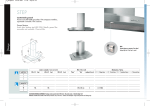
INFORMAZIONI COMMERCIALI PER I CONSUMATORI
COMMERCIAL INFORMATION FOR THE CONSUMER
I
GB
ISTRUZIONI PER L'USO S901-S902
INSTRUCTIONS FOR USE S901-S902
INFORMAZIONI TECNICHE
TECHNICAL INFORMATION
TYPE: FSLC
1
I
Il simbolo
sul prodotto o sulla confezione indica che il prodotto non deve essere considerato come
un normale rifiuto domestico, ma deve essere portato nel punto di raccolta appropriato per il riciclaggio di
apparecchiature elettriche ed elettroniche. Provvedendo a smaltire questo prodotto in modo appropriato, si
contribuisce a evitare potenziali conseguenze negative per l’ambiente e per la salute, che potrebbero derivare da
uno smaltimento inadeguato del prodotto. Per informazioni più dettagliate sul riciclaggio di questo prodotto,
contattare l’ufficio comunale, il servizio locale di smaltimento rifiuti o il negozio in cui è stato acquistato il prodotto.
Questo elettrodomestico è marcato conformemente alla Direttiva Europea 2002/96/CE sui rifiuti da apparecchiature
elettriche ed elettroniche (WEEE).
GB
The symbol
on the product or on its packaging indicates that this product may not be treated as
household waste. Instead it shall be handed over to the applicable collection point for the recycling of electrical
and electronic equipment. By ensuring this product is disposed of correctly, you will help prevent potential negative
consequences for the environment and human health, which could otherwise be caused by inappropriate waste
handling of this product. For more detailed information about recycling of this product, please contact your local
city office, your household waste disposal service or the shop where you purchased the product. This appliance
is marked according to the European directive 2002/96/EC on waste electrical and electronic equipment (WEEE).
2
I
INDICE
Avvertenze
Versioni d’uso
Installazione
Funzionamento
Manutenzione
3
Se l'apparecchio è provvisto di cavo alimentazione
e di spina, deve essere posto in modo che la spina
sia facilmente accessibile.
AVVERTENZE
* Evitare l'uso di materiali che causano fiammate
(flambè) nelle immediate vicinanze
dell'apparecchio. Nel caso di fritture fare
particolarmente attenzione al pericolo di incendio
che costituiscono olio e grassi. Particolarmente
pericoloso per la sua infiammabilità è l'olio già
usato. Non usare griglie elettriche scoperte. Per
evitare un possibile rischio di incendio attenersi
alle istruzioni indicate per la pulizia dei filtri
antigrasso e la rimozione di eventuali depositi di
grasso sull'apparecchio.
* La distanza minima tra la superficie del
piano di cottura e la parte inferiore del la cappa
deve essere 65 cm.
* L'aria raccolta non deve essere convogliata in
un condotto usato per lo scarico di fumi di
apparecchi alimentati con energia diversa da quella
elettrica (impianti di riscaldamento centralizzati,
termosifoni, scaldabagni, ecc.).
* Per lo scarico dell'aria da evacuare rispettare le
prescrizioni delle autorità competenti.
VERSIONI D’USO
* Prevedere un'adeguata areazione del locale quando
una cappa ed apparecchi alimentati con energia
diversa da quella elettrica (stufe a gas, ad olio, a
carbone, ecc.), vengono usati contemporaneamente.
La cappa aspirante evacuando l'aria potrebbe creare
una pressione negativa nella stanza. La pressione
negativa del locale non deve superare i 0,04 mbar,
evitando così il risucchio dei gas di scarico della
fonte di calore.
Pertanto bisogna attrezzare il locale con delle prese
d'aria che alimentino un flusso costante di aria fresca.
L'apparecchio è già predisposto sia per la versione
filtrante sia per la versione aspirante.
* Nella versione filtrante (dis.1) l'aria ed i vapori
convogliati dall'apparecchio, vengono depurati sia
da un filtro antigrasso sia da un filtro al carbone
attivo e rimessi in circolazione nell'ambiente
attraverso un foro praticato nella parte superiore del
pensile.
Quando l’etichetta dati tecnici interna alla cappa
mostra il simbolo
, l’apparecchio è in classe
II°, quindi non necessita di collegamento a terra.
* Nella versione aspirante (dis. 2) i vapori vengono
convogliati direttamente all'esterno, tramite un
condotto di evacuazione che si collega con la parte
superiore della parete o del soffitto. L'utilizzo del
filtro al carbone non è necessario.
Quando l’etichetta dati tecnici interna alla cappa
non mostra il simbolo
, l’apparecchio è in
classe I°, quindi necessita di collegamento a terra.
INSTALLAZIONE
* Nell'operazione di collegamento elettrico assicurarsi
che la presa di corrente sia munita di collegamento
a terra e verificare che i valori di tensione
corrispondono con quelli indicati nella targhetta
all'interno dell'apparecchio.
Prima di procedere all'installazione, per evitare danni
dell'apparecchio, disinserire i filtri antigrasso. La
rimozione dei filtri metallici antigrasso avviene
spingendo il filtro verso la parte posteriore della
cappa e facendolo ruotare verso il basso sganciandolo
dalla sua sede (dis.3).
* Prima di procedere a qualsiasi operazione di pulizia
o manutenzione è necessario togliere l'apparecchio
dalla rete.
Se l'apparecchio non è provvisto di cavo flessibile
non separabile e di spina, o di altro dispositivo che
assicuri la omnipolare disinserzione dalla rete, con
una distanza di apertura dei contatti di almeno 3
mm, allora tali dispositivi di separazione dalla rete
devono essere previsti nell'istallazione fissa.
I requisiti essenziali prima di effettuare il montaggio
dell’apparecchio sono:
* Aver praticato l’apertura necessaria sul fondo del
pensile giusta ad accogliere l’apparecchio (dis. 4 per
S901, dis. 4A per S902).
* Predisporre l’alimentazione elettrica.
* Predisporre, sia in versione filtrante, sia in versione
aspirante, il foro evacuazione aria.
4
Per istallare l’apparecchio regolare la posizione delle
molle laterali di aggancio tramite le apposite viti (dis.
5), in rapporto allo spessore del pannello forato su
cui andrà ancorato.
Inserire il gruppo nella sede praticata nel pensile fino
al completo bloccaggio delle molle laterali.
Utilizzare le viti in dotazione per il definitivo bloccaggio
tramite i fori interni dell’apparecchio (dis. 6).
Ripristinare i filtri antigrasso.
La pulizia del filtro antigrasso può essere eseguita a
mano o in lavastoviglie.
La pulizia avviene in rapporto all'uso, almeno una
volta ogni due mesi.
* Nel caso d'uso dell'apparecchio in versione filtrante,
è necessario sostituire il filtro carbone attivo (dis.7)
periodicamente.
Il filtro ai carboni attivi si rimuove togliendo prima
il filtro antigrasso (dis.3) e poi tirando l'apposita
linguetta in plastica del filtro carbone sganciandolo
dalla sua sede (dis.7). Il filtro al carbone viene inserito
nell'operazione inversa. La sostituzione del filtro al
carbone avviene in rapporto all'uso, almeno una volta
ogni sei mesi.
Bloccaggio valvola
Attenzione! Prima di collegare il tubo flessibile uscita
aria al motore, accertarsi che la valvola di non ritorno
posta sulla bocca del motore sia libera di roteare.
* Versione aspirante
Collegare la flangia della cappa al foro di evacuazione
tramite un tubo adatto. Effettuare il collegamento
elettrico mediante il cavo alimentazione.
* Rimozione serbatoio olio
Dopo aver rimosso i filtri in acciaio ed eventualmente
quelli ai carboni attivi, con una mano sorreggere il
serbatoio olio e con l’altra allentare i pomelli come
indicato in fig.8, far scorrere quindi il serbatoio verso
il basso facendo attenzione a non versare l’olio.
* Versione filtrante
Collegare alla flangia un tubo adatto che convogli
l’aria fino alla parte superiore del pensile. Effettuare
il collegamento elettrico mediante il cavo
alimentazione.
* Per la pulizia dell'apparecchio stesso viene
consigliato l'uso di acqua tiepida e detersivo neutro,
evitando l'uso di prodotti contenenti abrasivi. Per la
pulizia di apparecchi in acciaio viene consigliato l'uso
di prodotti specializzati, seguendo le istruzioni indicate
sul prodotto.
FUNZIONAMENTO
Att. nel caso di smontaggio dell’apparecchio dal pensile
svitare le viti di fissaggio definitivo (dis. 6), togliere i
filtri antigrasso (dis. 3), se ci sono i filtri ai carboni
attivi (dis. 7) e agire sulla maniglietta delle molle poste
internamente al gruppo con la forza necessaria a
sganciare l’apparecchio dal pensile.
Mod. S901-S902 (dis. 10)
A: Interruttore on/off luce
B: Interruttore on (I velocità)/off motore
C: Interruttore II velocità
D: Interruttore III velocità
E: Interruttore IV velocità
F: Temporizzatore 10 minuti
* La sostituzione del cavo alimentazione deve essere
eseguita esclusivamente da personale autorizzato.
* Per sostituire la lampada dicroica, sfilare la lampada
(dis.9) inserendo un piccolo giravite o un qualsiasi
utensile appuntito tra lampada e il suo supporto
cromato, e sostituire con una lampada delle stesse
caratteristiche.
MANUTENZIONE
* Un'accurata manutenzione garantisce un buon
funzionamento ed un buon rendimento nel tempo.
* Una cura particolare va rivolta al pannello
antigrasso.
La rimozione del filtro avviene spingendolo verso la
parte posteriore della cappa e facendo ruotare il filtro
verso il basso sganciandolo dalla sua sede (dis.3).
Il filtro viene inserito nell'operazione inversa.
Dopo 30 ore di esercizio della cappa la pulsantiera,
segnalerà la saturazione del filtro, mediante
l'illuminazione di tutti i tasti. Per il reset, schiacciare
il tasto temporizzatore
.
5
GB
CONTENTS
Warnings
Uses
Installation
Working
Maintenance
6
* The use of materials which can burst into flames
should be avoided in close proximity of the
appliance. When frying, please pay particular
attention to fire risk due to oil grease. Being highly
inflammable, fried oil is especially dangerous. Do
not use uncovered electric grills. In order to avoid
possible fire risk, all instructions for grase-filter
cleaning and for removing eventual grease deposits
should be strictly followed.
WARNINGS
* The cooker surface and the inferior part of the cooker
hood must be at a minimun distance of 65 cm.
* The air sucked can't be conveyed through or into
a duct used to let out fumes from appliances fed
by energy other than electric power (eg. centralized
heating, radiators, water-heaters, etc.).
USES
* To evacuate the air outlet, please comply with
the pertaining rules given by competent authorities.
The appliance is already arranged both for filtering
and for suction performances.
* Provide the room with an adequate aeration when
a cooker hood and appliances fed by energy other
than electric power (gas-, oil-, or coal- stoves, etc.)
are used simultaneously. The cooker hood, when
evacuating the sucked air, could generate a negative
pressure in the room- which can't exceed the limit
of 0.04 mbar, in order to avoid the suck of exhausts
deriving from the heat-source. Therefore the room
should be provided with air-intakes to allow a costant
flow of fresh air.
* In its filtering version (Fig.1), the air and fumes
conveyed by the appliance are depured both by a
grease filter and by an active coal filter, and put again
into circulation through the hole made on the top of
the cabinet.
* In its sucking version (Fig.2), fumes are directly
conveyed outside, through an evacuation duct
connected with the superior part of the wall or the
ceiling. Both coal filter and air deflector are not
necessary in this case.
If the rating lable in the cooker-hood shows
the symbol
, the appliance is built in
class II° and it does not need any earth
connection.
INSTALLATION
If the rating lable in the cooker-hood does
not show the symbol
, the appliance is
built in class I° and it needs the earth
connection.
* Before installing the appliance, in order not to
damage the appliance itself, the metal grase filter
should be removed. These filter could be removed
by pushing the handles towards the back side of the
cooker hood and turning it downwards to unfasten
it from its slot. (Fig.3).
* When performing the electrical connections on the
appliance, please make sure that the current-tap is
provided with earth connection and that voltage
values correspond to those indicated on the label
placed inside the appliance itself.
Essential precautions to respect before installing the
appliance are the following:
To have made a cut-out on the bottom of the cabinet
which is suitable to hold the appliance in position (fig.4
for S901, fig. 4A for S902).
* prepare the power supply.
* prepare a hole for the exhaust of the air both in the
filtering and in the exhauting version.
* Before carrying out any cleaning or maintaining
operations, the appliance needs to be removed from
the electric grid. If the appliance is not provided with
a non-separable flexible cable and plug, or with
another device ensuring omnipolar disconnections
from the grid, with an opening distance between the
contacts of at least 3 mm, then such disconnecting
devices must be supplied within the fixed installation.
If the fixed appliance is endowed with a supply cord
and a plug, the appliance has to be put in a place
where the plug can be reached easily.
7
To install the appliance, adjust the position of the stop
side-springs using the appropriate screws (fig.5),
according to the thickness of the board previously
drilled, on which the appliance will be fixed.
Insert the built-in unit in the hole made in the cabinet
until the stop click of the side- springs is heard and the
built-in unit is blocked.Insert the screws provided in the
holes inside the appliance (fig.6) to block it completely.
Put the grease filter again
The coal filter needs replacing depending on the use,
but however every six months at least.
Blocking of the stop valve
* How to remove the oil tank. After having removed
the grease filters and eventually the active coal filters,
please hold the oil tank up by one hand and ioosen
the three handles by the other hand as showed in fig.8.
Then let the tank slide downwards making attention
in order to avoid the leak of oil.
Warning!
Before connecting the flexible exhausting pipe to the
motor, make sure the stop valve, which is on the air
outlet of the motor, can swing.
Exausting version
Connect the flange to the exhausting hole with an
appropriate pipe. Connect the appliance with the
electrical mains through the supply cord.
* To clean the appliance itself tepid water and neutral
detergent are recommended, while abrasive products
should be avoided. For steel appliances specialized
detergents are recommended (please follow the
instructions indicated o the product itself to obtain
the desired results).
Filtering version
Connect the flange with a pipe suitable to convey the
air to the top of the cabinet. Connect the appliance
with the electrical mains through the supply cord.
* Warning! To take down the appliance from the
cabinet, remove the definitive fixing screws (fig. 6)
using a screw-driver, get off the grease filters (fig.3)
and the active carbon filters, if they are inserted (fig.
7). Act on the small handle of the springs, which are
inside the built-in unit, with the necessary strength
to unhook the appliance from the cabinet.
WORKING
Mod. S901-S902 (fig. 10)
A: Light switch on/off
B: Motor switch on speed 1/off
C: Motor switch on speed 2
D: Motor switch on speed 3
E: Motor switch on speed 4
F: 10-minutes timer
* If the supply cord is damaged, it must be replaced
by the manufacturer or its sevice agent or a similarly
qualified person in order to avoid a hazard.
To replace the dichroic lamp, remove the lamp (fig.9)
by inserting a screwdriver or another sharp too
between the lamp and its chrom support and replace
it with a l’appareil lamp of the same kind.
MAINTENANCE
* An accurate maintenance guarantees good
functioning and long-lasting performance.
* Particular care is due to the grease filter panel. It
can be removed by pushing its special handle toward
the back-side of the cooker hood and turning the filter
downwards so to unfasten it from its slot (Fig.3).
To insert the filter just perform the opposite operation.
After 30 hours working, the push button control panel
will signal the saturation of the grease filter by lighting
all the buttons. Press the timer button to reset
.
The grease filter needs cleaning by regular handwashing or in dishwashers every two months at least
or depending on its use.
* In case the appliance is used in its filtering version,
the active coal filter (Fig.7) needs to be periodically
replaced. The coal filter can be removed by removing
the grease filter first (Fig.3), and by pulling its special
plastic tongue until it is unfastened from its slot. Reinsert the coal filter by operating in the opposite way.
8
1
2
3
4
4/A
9
5
6
7
8
9
10
10
90001100020 - 12/06
11