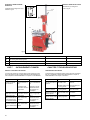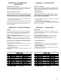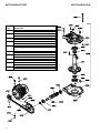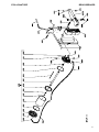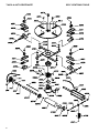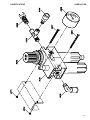
1
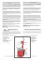
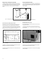
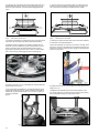
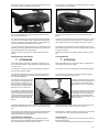
670
I
GB
SMONTAGOMME
SEMIAUTOMATICO
SEMI-AUTOMATIC
TYRE CHANGER
Manuale di istruzioni per l’uso e la manutenzione dello
Instructions and maintenance manual for
SMONTAGOMME PER AUTOVETTURA
CARS TYRE CHANGER
Modello 670
Matricola N°
Anno di costruzione
COSTRUTTORE:
OMA SpA
Via dell’ Artigianato, 64
36045 LONIGO (VI) - ITALY
Telefono ++ / +444 / 436199
Telefax ++ / +444 / 436208
Model 670
Serial N°
Year of manufacture
MANUFACTURER:
OMA SpA
Via dell’ Artigianato, 64
36045 LONIGO (VI) - ITALY
Telefono ++ / +444 / 436199
Telefax ++ / +444 / 436208
1° Emissione 29 Settembre 1997
1st Edition - September 29,1997
CENTRO DI ASSISTENZA AUTORIZZATO:
AUTHORISED SERVICE CENTRE:
Rev.5 .........................................06/03/2001
1
Indice
Contents
Imballaggio, trasporto
e stoccaggio
Packing, transport and storage
Page 3
Pag. 3
Introduzione
Pag. 3
Introduction
Page 3
Cap.1 Descrizione della
macchina
Chapter 1
Pag. 4
Cap.2 Specifiche tecniche
Pag. 5
Chapter 2
Description
of the machine
Page 4
Technical
specifications
Page 5
Cap.3 Sicurezza
Pag. 6
Chapter 3
Safety
Page 6
Cap.4 Installazione
Pag.10
Chapter 4
Installation
Page 10
Cap.5 Funzionamento ed uso
Pag.16
Chapter 5
Operating principles
and use
Page16
Cap.6 Manutenzione
Pag.20
Chapter 6
Maintenance
Page 20
Cap.7 Inconvenienti e rimedi
Pag.22
Chapter 7
Troubleshooting
Page 22
Appendix A
Special notes
Page 23
Appendix B
Spare parts
Page 23
Appendice A
Appendice B
Informazioni
particolari
Pag.23
Parti di ricambio
Pag.23
Schemi di funzionamento
Pag.36
(Riservati al personale specializzato
del centro di assistenza autorizzato)
2
Working schemes
Page 36
(Reserved to specialised personnel
from authorised service centre)
IMBALLAGGIO, TRASPORTO E
STOCCAGGIO
PACKING, TRANSPORT AND
STORAGE
LE OPERAZIONI DI IMBALLAGGIO, SOLLEVAMENTO, MOVIMENTAZIONE, TRASPORTO E DISIMBALLO DEVONO ESSERE AFFIDATE ESCLUSIVAMENTE A PERSONALE CHE SIA
ESPERTO IN TALI OPERAZIONI E CHE CONOSCA BENE LO
SMONTAGOMME ED IL PRESENTE MANUALE
ALL PACKING, LIFTING, HANDLING, TRANSPORT AND
UNPACKING OPERATIONS ARE TO BE PERFORMED
EXCLUSIVELY BY EXPERT PERSONNEL WITH KNOWLEDGE
OF THE TYRE CHANGER AND THE CONTENTS OF THIS MANUAL
IMBALLAGGIO
Lo smontagomme viene inviato su pallet, ricoperto con un involucro di cartone, del peso medio di 213Kg.
PACKING
The tyre changer is sent on pallets, covered with carton, weighing
approximately 213 Kg.
SOLLEVAMENTO E MOVIMENTAZIONE
I pallet devono essere movimentati mediante carrelli elevatori.
LIFTING AND HANDLING
The pallets must be moved with a lift truck.
I mezzi scelti devono essere idonei al sollevamento e allo spostamento in sicurezza, tenendo conto di dimensioni, peso, baricentro,
sporgenze e parti delicate da non danneggiare.
The equipment chosen must be suitable for safe lifting and moving,
bearing in mind the dimensions, weight, barycentre, juts, and
fragile parts not to be damaged.
STOCCAGGIO
Gli imballi devono sempre essere conservati in luoghi coperti e protetti a temperature comprese fra -10°C e +40°C. e non devono essere esposti ai raggi diretti del sole.
STORAGE
Packed machinery must always be kept in a covered, protected
place, at a temperature between -10 °C e + 40°C, and must not be
exposed to direct sunlight.
IMPILAMENTO DEI PACCHI
Il tipo di imballo previsto prevede la possibilità di impilare in magazzino fino a 3 imballi uno sull’altro, purchè vengano correttamente
disposti ed assicurati contro la caduta.
Nei cassoni dei camion o nei containers si possono impilare fino a
2 imballi purchè vengano reggiati bene ed assicurati contro la caduta.
PACKAGES STACKING.
The type of packing allows the possibility of stacking up to 3 packages, provided they are restrained to prevent falling.
Up to 2 pallets may be stacked one upon the other on lorries or in
containers if properly positioned and provided they are restrained to prevent falling.
APERTURA DEGLI IMBALLI
All’arrivo verificare che la macchina non abbia subito danni durante
il trasporto e che ci siano tutti i pezzi indicati nella lista di spedizione.
Gli imballi devono essere aperti adottando tutte le precauzioni per
evitare danni alle persone e ai pezzi della macchina (evitare cadute di pezzi dal pallet durante l’apertura).
OPENING THE CRATES
When the crates arrive, check that the machine has not been
damaged during transport and that all the listed parts are present.
The crates must be opened using all possible precautionary
measures to avoid damaging the machine or its parts. Make sure
that parts do not fall from the crate during opening.
ELIMINAZIONE DELL’IMBALLO
Il legno del pallet e il cartone dell’involucro possono essere riutilizzati o riciclati.
DISPOSAL OF CRATES
The wood of the pallets and the package carton may be re-used or
recycled.
INTRODUCTION
INTRODUZIONE
I
I
ATTENZIONE
WARNING
Questo manuale è stato scritto per il personale di officina addetto all’uso dello smontagomme (operatore) e per il tecnico
addetto alla manutenzione ordinaria (manutentore) pertanto,
prima di effettuare qualsiasi operazione sullo smontagomme
e/o sul suo imballaggio, occorre leggere attentamente tutto il
manuale, poichè esso contiene informazioni importanti per:
This manual has been prepared for workshop personnel expert in the use of the tyre changer (operator) and technicians
responsible for routine maintenance (maintenance fitter); read
the manual before carrying out any operation with the tyre
changer and/or the packing. This manual contains important
information regarding:
•
•
•
LA SICUREZZA DELLE PERSONE addette all’uso ed alla
manutenzione ordinaria,
LA SICUREZZA DELLO SMONTAGOMME.
•
THE PERSONAL SAFETY of operators and maintenance
workers,
TYRE CHANGER SAFETY,
CONSERVAZIONE DEL MANUALE
Il manuale è parte integrante dello smontagomme e deve sempre
accompagnarlo, anche in caso di vendita.
Esso deve sempre essere conservato in vicinanza dello smontagomme, in luogo facilmente accessibile.
L’operatore ed il manutentore devono poterlo reperire e consultare
rapidamente in qualsiasi momento.
CONSERVING THE MANUAL
The manual is an integral part of the tyre changer, which it should
always accompany, even if the unit is sold.
The manual must be kept in proximity of the tyre changer, in an easily accessible place.
The operator and maintenance staff must be able to locate and
consult the manual quickly and at any time.
SI RACCOMANDA, IN PARTICOLARE, UNA LETTURA ATTENTA
E RIPETUTA DEL CAPITOLO 3, CHE CONTIENE IMPORTANTI
INFORMAZIONI E AVVISI RELATIVI ALLA SICUREZZA.
ATTENTIVE AND REPEATED READING OF CHAPTER 3,
CONTAINING IMPORTANT INFORMATION AND SAFETY
WARNINGS, IS PARTICULARLY RECOMMENDED.
3
Il sollevamento, il trasporto, il disimballo, il montaggio, l’installazione e la messa in servizio, la taratura e le registrazioni iniziali, la
manutenzione STRAORDINARIA, la riparazione, la revisione, lo
spostamento e lo smantellamento dello smontagomme devono essere eseguiti dai tecnici specializzati dei RIVENDITORI AUTORIZZATI o dei CENTRI ASSISTENZA AUTORIZZATI dal Costruttore (vedere centro assistenza autorizzato indicato nel frontespizio):
Lifting, transport, unpacking, assembly, installation, starting up, initial adjustment and testing, EXTRAORDINARY maintenance, repair, overhauls, transport and dismantling of the tyre changer must
be performed by specialised personnel from the LICENSED DEALER or a SERVICE CENTRE authorised by the manufacturer
(see authorised dealer on frontispiece).
Il costruttore non risponde di alcun danno a persone, veicoli od oggetti causati dagli interventi sopracitati se effettuati da personale
non autorizzato o da un uso improprio o non consentito dello
smontagomme
The manufacturer declines all responsibility for injury to persons or
damage to vehicles or objects when any of the above mentioned
operations has been performed by unauthorised personnel or
when the tyre changer has been subject to improper use.
Per tutte queste attività vengono indicati, nel presente manuale,
soltanto gli aspetti (operativi e di sicurezza) che possono essere
utili anche all’operatore ed al manutentore per comprendere meglio
la struttura ed il funzionamento dello smontagomme e per un suo
migliore utilizzo.
This manual indicates only the operative and safety aspects that
may prove useful to the operator and maintenance worker, in better understanding the structure and operation of the tyre changer
and for best use of the same.
Per comprendere il linguaggio adottato nel presente manuale, l’operatore deve possedere esperienza specifica nelle attività di officina, di assistenza, manutenzione e riparazione dei veicoli nonchè la
capacità di interpretare correttamente i disegni e le descrizioni riportate nel manuale e la conoscenza delle norme antinfortunistiche
generali e specifiche vigenti nel paese in cui viene installato lo
smontagomme.
Gli stessi criteri valgono per la scelta del tecnico manutentore che
dovrà, inoltre, possedere le conoscenze tecniche specifiche e specialistiche (meccaniche, elettriche) necessarie per effettuare in sicurezza gli interventi previsti nel manuale.
In order to understand the terminology used in this manual, the
operator must have specific experience in workshop, service,
maintenance and repair activities, the ability to interpret correctly
the drawings and descriptions contained in the manual and be acquainted with the general and specific safety rules relevant to the
country in which the machine has been installed.
The same applies to the maintenance fitter, who must also possess specific and specialised knowledge (mechanical, engineering)
needed to perform the operations described in the manual in complete safety.
Nel testo del manuale troverete spesso le diciture “operatore” e
“manutentore” il cui significato è il seguente:
OPERATORE: persona addetta all’uso dello smontagomme.
MANUTENTORE: persona addetta alla manutenzione ordinaria
dello smontagomme.
CAP.1. DESCRIZIONE DELLA
MACCHINA
The words “operator” and “maintenance fitter” used in this manual are construed as follows:
OPERATOR: person authorised to use the tyre changer
MAINTENANCE FITTER: person authorised for routine maintenance of the tyre changer.
CHAPTER 1 MACHINE DESCRIPTION
Lo smontagomme è una macchina semiautomatica progettata e
costruita per essere utilizzata quale attrezzatura per lo smontaggio
ed il rimontaggio dei pneumatici su cerchi di ruote di autoveicoli,
motocicli e motoveicoli.
The tyre changer is a semi-automatic machine, designed and built
as tool for changing tyres on cars, motorcars or vans wheel rims.
È composta principalmente dalle seguenti parti:
The tyre changer consists of the following main parts:
1 - Braccio operante
2 - Utensile di smontaggio
3 - Tavola autocentrante
4 - Stallonatore
5 - Pedaliera
6 - Pomello regolazione braccio
7 - Leva bloccaggio
8 - Pistola di gonfiaggio
1 - Operating arm;
2 - Mount-demount tool;
3 - Self-centring table;
4 - Bead-breaker;
5 - Pedals;
6 - Arm regulating knob;
7 - Blocking lever;
8 - Inflating gun
7
6
1
8
2
3
5
4
Fig.1
4
Principali parti della macchina
Fig.1 Main machine parts
CAP.2
SPECIFICHE TECNICHE
CHAPTER.2
TECHNICAL
SPECIFICATIONS
Diametro max. ruota autovettura...............950 mm.
Max. car wheel diameter.....................................950 mm
Larghezza max. ruota................................9"
Max. wheel width ................................................9”
Diametro min/max. cerchio interno............13"-21"
Min/max. internal rim diameter ...........................13”-21”
Diametro min/max. cerchio esterno...........10"-18"
Min/max. external rim diameter ..........................10”-18”
Diametro min/max. cerchio motociclo .......8"-22"
Min/max. motorcycle rim diameter .....................8”- 22”
I
ATTENZIONE
I
ATTENTION
Per smontare e rimontare ruote di motocicli è necessario disporre della serie di morsetti di adattamento (OPTIONAL).
To change motorcycle wheels fitting clamps series
(OPTIONAL) are needed.
Peso totale dello smontagomme ...............circa 193 Kg
Tyre changer total weight....................................ca. 193 Kg.
Rumorosità ................................................70dB(A)/1m
Noisiness ............................................................70dB(A)/1m
Temperatura di funzionamento : ...............-10°C / +50°C
Working temperature ..........................................-10°C/+50°C
Forza dello stallonatore .............................2000 Kg.
Bead-breaker strength ........................................2000 Kg
Ambiente di lavoro: locale chiuso.
Work environment: close room
Potenza del motore elettrico......................0,55 KW
Electrical motor power ........................................0,55 Kw
Tensione....................................................400V trif.+/- 5%
Voltage................................................................400V 3-ph. +/-5%
Frequenza .................................................50 Hz
Frequency ...........................................................50 Hz
Assorbimento: ...........................................a 400V 1,6A
..................................................................a 230V 2,8A
Absorption...........................................................if 400V1,6A
............................................................................if 230V2,8A
DATI DI TARGA
DETAILS OF CE LABEL
5
CAP.3
SICUREZZA
É estremamente importante leggere questo capitolo attentamente
ed in ogni sua parte poichè contiene importanti informazioni sui rischi che operatore e manutentore possono correre in caso di un
uso errato dello smontagomme.
Nel testo che segue troverete chiare spiegazioni su alcune situazioni di rischio o pericolo che si possono verificare durante l’uso e
la manutenzione dello smontagomme, sui dispositivi di sicurezza
adottati e sul loro uso corretto, sui rischi residui e sui comportamenti da tenere (precauzioni generali e specifiche per eliminarli o
neutralizzarli).
I
ATTENZIONE:
Lo smontagomme è stato progettato e costruito
per essere utilizzato come attrezzatura per lo
smontaggio ed il rimontaggio dei pneumatici su
cerchi di ruote di autoveicoli, motocicli e motoveicoli. Ogni altro uso non è consentito
Il costruttore non risponde di alcun danno a persone, veicoli od oggetti causati dall’uso improprio o non consentito dello smontagomme.
É estremamente importante che l’operatore agisca soltanto dalla postazione di comando indicata in fig.33 e rispettando tutte le modalità elencate
di seguito.
É vietato a chiunque sostare entro la zona di lavoro indicata in fig.12 durante le fasi di lavoro dello
smontagomme.
NON UTILIZZARE LA MACCHINA SENZA LE PROTEZIONI O CON LE PROTEZIONI DISATTIVATE.
CHAPTER 3
SAFETY
It is vital to read this chapter of the manual carefully and from beginning to end as it contains important information regarding the
risks that the operator or maintenance fitter may be exposed to in
case of improper use of the tyre changer.
The following text contains clear explanations regarding some situations of risk or danger that may arise during the operation or
maintenance of the tyre changer, the safety devices installed and
the correct use of such systems, residual risks and operative procedures to use (general and specific precautions to eliminate potential hazards).
I
WARNING:
Tyre changer is designed and built as a tool to
change tyres on car, motorcycles, or vans wheel
rims. All other uses are unauthorised.
The manufacturer disclaims all liability for injury
to persons or damage to vehicles and other
property caused by the incorrect and
unauthorised use of the tyre changer.
The operator must remain in the command place
as shown in fig.33 in the respect of all the rules listed below.
The presence of persons inside the danger zone
marked in fig.12 is strictly prohibited during the
tyre changer working operations.
DO NOT USE THE TYRE CHANGER WITHOUT
PROTECTION DEVICES OR WITH THE PROTECTION DEVICES INHIBITED.
IL MANCATO RISPETTO DI QUESTE NORME
PUO’ RECARE GRAVI DANNI ALLE PERSONE E
ALLO SMONTAGOMME.
FAILURE TO COMPLY WITH THESE
REGULATIONS CAN CAUSE SERIOUS INJURY
TO PERSONS, AND IRREPARABLE DAMAGE TO
THE TYRE CHANGER.
PRECAUZIONI GENERALI
GENERAL PRECAUTIONS
L’operatore ed il manutentore sono tenuti al rispetto delle prescrizioni contenute in leggi e norme antinfortunistiche vigenti nel paese
in cui è installato lo smontagomme.
The operator and the maintenance fitter are required to observe
the prescriptions of accident prevention legislation in force in the
country of installation of the tyre changer.
Devono inoltre:
operare sempre dalle postazioni di lavoro previste ed indicate nel
manuale;
non rimuovere nè disattivare i carter e le protezioni meccaniche,
elettriche, o di altra natura;
prestare attenzione agli avvisi di sicurezza riportati nelle targhette
applicate sulla macchina e nel manuale.
Furthermore, the operator and maintenance fitter must:
Always work in the scheduled working area as shown in the
manual.
Never remove or deactivate the guards and mechanical, electrical,
or other types of safety devices;
read the safety notices affixed to the machine and the safety
information in this manual.
Nel testo del manuale gli avvisi di sicurezza saranno evidenziati
nelle forme seguenti:
In the manual all safety notices are shown as follows:
PERICOLO: Indica un pericolo imminente che può causare danno
alle persone (gravi lesioni o anche la morte).
DANGER: Indicates imminent danger that can result in serious injury or death.
ATTENZIONE: Indica situazioni e/o comportamenti rischiosi che
possono causare danni alle persone (lesioni più o meno gravi e/o
anche la morte).
WARNING: Indicates situations and/or types of manoeuvres that
are unsafe and can cause injuries of various degrees or death.
CAUTELA: Indica situazioni e/o comportamenti rischiosi che possono causare danni di minore gravità alle persone e/o danni al
smontagomme, al veicolo o ad altre cose.
CAUTION: Indicates situations and/or types of manoeuvres that
are unsafe and can cause minor injury to persons and/or damage
the tyre changer, the vehicle or other property.
RISCHIO DI FOLGORAZIONE: è un particolare avviso di sicurezza che viene riportato sul smontagomme, tramite targhetta, in alcuni punti dove è particolarmente elevato il rischio di forti scosse elettriche.
RISK OF ELECTRIC SHOCK: specific safety notice affixed to the
tyre changer in areas where the risk of electric shock is particularly
high.
6
RISCHI E PROTEZIONI
Vediamo ora quali rischi possono correre gli operatori o il manutentore nelle fasi d’uso dello smontagomme e quali protezioni sono state adottate dal
costruttore per ridurre al minimo tali rischi:
RISKS AND PROTECTION DEVICES
We shall now examine the risks to which operators or maintenance fitters, together with the protection devices adopted by the manufacturer to
reduce all such hazards to the minimum:
RISCHIO DI URTO (1)
Con la testa contro al braccio operante. Lavorare
sempre in posizione eretta e facendo attenzione
alle parti sporgenti.
RISK OF IMPACT (1)
Operator’s head may bump against the operating
arm. Always work keeping an erect position and
paying attention to juts.
Fig.2
Rischio di urto (1)
RISCHIO DI URTO (2)
Contro alla sporgenza del pistone dello stallonatore. Il costruttore ha previsto per il caso, una copertura adeguata. Prestare attenzione comunque
quando si lavora attorno alla macchina.
Fig.3
Rischio di urto (2)
Fig.2 Risk of impact (1)
RISK OF IMPACT(2)
Against the juts of the bead-breaker piston. A cover has been projected by the manufacturer, in
any case, the operator has to keep attention while working.
Fig.3 Risk of impact (2)
RISCHIO DI SCHIACCIAMENTO DELLA GAMBA
Non infilare la gamba fra la pala dello stallonatore
ed il suo appoggio (fig.4).
RISK OF LEG CRUSHING
Never put his leg between the bead-breaker and
its support (fig.4).
UN USO IMPROPRIO DELLO STALLONATORE PUÒ CAUSARE INCIDENTI
GRAVISSIMI.
AN IMPROPER USE OF THE BEADBREAKER MAY CAUSE DEADLY
ACCIDENTS.
Fig.4
Rischio di schiacciamento della gamba
RISCHIO DI SCHIACCIAMENTO (2)
Fra il braccio operante e la vite di regolazione del
braccio stesso. Non infilare le mani fra la vite di fermo ed il braccio per evitare schiacciamenti della
mano.
Fig.5
Rischio di schiacciamento (1)
RISCHIO DI SCHIACCIAMENTO (2)
Fra i morsetti della tavola autocentrante. Non infilare mai le mani fra i morsetti della tavola autocentrante e non azionare mai tali morsetti senza
pneumatico sulla tavola. Durante le fasi di manutenzione ed ingrassaggio è obbligatorio scollegare la macchina da ogni fonte di alimentazione
(elettrica e pneumatica).
Fig.6
Rischio di schiacciamento (2)
Fig.4 Risk of leg crushing.
RISK OF CRUSHING (1)
Between the operating arm and the arm regulating screw. never put hands between the halting
screw and the arm, in order to avoid the hand
being crushed.
Fig.5 Risk of crushing (1)
RISK OF CRUSHING (2)
Between the self-centring table clamps. Never
put hands between the clamps and never set
them working without a tyre on the table. During
maintenance and greasing phases the operator
must disconnect the machine from any feeding
source (electric or pneumatic).
Fig.6 Risk of crushing (2).
7
RISCHIO DI SCIACCIAMENTO (3)
Durante l’operazione di gonfiaggio allontanare
le mani dal tallone del pneumatico.
Fig.7
Rischio di schiacciamento (3)
RISCHIO DI URTO (3)
Prestare molta attenzione nell’uso della leva
alzatallone, in particolare per evitare lo scivolamento della stessa nel momento di sforzo e
l’eventuale urto contro al viso o altra parte del
corpo.
Fig.8
Rischio di urto (3)
RISK OF CRUSHING (3)
keep hands away from the tyre during blowing
up operation.
Fig.7 Risk of crushing (3).
RISK OF IMPACT(3)
Pay attention to the bead-lifting lever, in particular to avoid its slipping in the stress moment, and to avoid its bumping against the
operator.
Fig.8 Risk of impact (3).
RISCHIO DI SCIVOLAMENTO
Dovuto a zone del pavimento sporche di lubrificanti (fig.9).
SLIPPING
This risk may arise due to spillage of lubricants in the surrounding area (fig.27).
TENERE PULITA LA ZONA VICINA ALLO
SMONTAGOMME pulendo le MACCHIE D’OLIO.
Al fine di evitare il rischio di scivolamento utilizzare i mezzi individuali previsti (scarpe antinfortunistiche).
ALWAYS KEEP THE AREA SURROUNDING THE TYRE CHANGER CLEAN by removing all OIL SPILLS.
To avoid the risk of slipping, make use of the
recommended personal protection (anti-slip
footwear).
Fig.9
Rischio di scivolamento
RISCHIO DI FOLGORAZIONE
Accanto a parti dello smontagomme in cui si
trovano fili elettrici evitate getti d’acqua, di vapore (da pulitrice a vapore), di solventi o vernici.
Fig.10
Rischio di folgorazione
Fig.9 Slipping risk
RISK OF ELECTRIC SHOCK
Risk of electric shock in areas of the tyre
changer housing electrical wiring.
Do not use jets of water, steam (high pressure
wash units), solvents or paint near the tyre
changer.
Fig.10 Risk of electric shock
RISCHIO DA ILLUMINAZIONE NON IDONEA
L’operatore ed il manutentore devono verificare che tutte le zone
dello smontagomme siano sempre illuminate in maniera uniforme
ed in conformità a quanto previsto dalla normativa vigente nel
luogo di installazione.
RISKS RELATED TO INAPPROPRIATE LIGHTING.
The operator and the maintenance fitter must be able to assure
that all the areas of the tyre changer are properly and uniformly illuminated in compliance with the laws in force in the place of installation.
RISCHIO DI ANOMALIE DURANTE IL FUNZIONAMENTO
Nel caso in cui l’operatore avvertisse rumori e vibrazioni anomale o
comunque tali da comportare una situazione di pericolo deve immediatamente arrestare la fase di lavoro, sconnettere lo smontagomme dalla rete elettrica ed avvertire il centro di assistenza autorizzato indicato nel frontespizio
RISK OF ANOMALY DURING OPERATION
If the operator hears unusual noises or vibrations or something that
may be dangerous, he must immediately stop the working phase,
unplug the tyre changer and call the authorised service centre marked on the frontispiece.
8
RISCHIO DI ROTTURE DI COMPONENTI DURANTE IL
FUNZIONAMENTO
Il costruttore ha utilizzato materiali e procedure progettuali e costruttive idonee all’uso previsto e atte a creare un’apparecchiatura
affidabile e sicura ma è necessario rispettare l’uso per cui è stato
progettato lo smontagomme nonchè le frequenze delle ispezioni e
delle manutenzioni consigliate nel capitolo 6 “MANUTENZIONE”.
RISK OF COMPONENT FAILURE DURING OPERATION.
The manufacturer has used appropriate materials and construction
techniques in relation to the specified use of the machine in order
to manufacture a reliable and safe tyre changer. Note however,
that the tyre changer must be used in conformity with manufacturer’s prescriptions and the frequency of inspections and maintenance work recommended in chapter 6 “MAINTENANCE” must be
observed.
RISCHI A TERZI
L’operatore deve accertarsi che non vi siano persone vicino allo
smontagomme durante le normali o straordinarie fasi di lavoro e di
manutenzione.
RISKS TO OTHER PEOPLE
The operator must check unauthorised persons are not near the
tyre changer during operation and maintenance phases.
Ogni uso dello smontagomme, diverso da quello per cui è stato progettato può creare incidenti, anche molto gravi, alle persone che stanno lavorando nelle immediate vicinanze.
É pertanto estremamente importante attenersi scrupolosamente a tutte le regole riguardanti l’uso, la manutenzione e la
sicurezza riportate in questo manuale.
All uses of the tyre changer other than the uses for which it
was designed are liable to give rise to serious accidents involving the persons working in the immediate vicinity of the unit.
It is therefore essential to adhere scrupulously to all regulations regarding use, maintenance and safety contained in this
manual.
AVVISI DI SICUREZZA E TARGHETTE APPLICATI SULLA
MACCHINA.
SAFETY WARNINGS ON THE MACHINE
Fig.11 Avvisi di sicurezza e targhette applicati alla macchina
Fig.11
Safety notices and data plates affixed to the machine
9
CAP.4
INSTALLAZIONE
CHAPTER 4
INSTALLATION
QUESTE OPERAZIONI SONO DI COMPETENZA ESCLUSIVA
DEI TECNICI SPECIALIZZATI INCARICATI DAL COSTRUTTORE O DAI RIVENDITORI AUTORIZZATI .
SE EFFETTUATE DA ALTRE PERSONE POSSONO CREARE
SITUAZIONI DI PERICOLO E CAUSARE GRAVI DANNI ALLE
PERSONE E/O ALLO SMONTAGOMME.
THE FOLLOWING OPERATIONS MUST BE PERFORMED EXCLUSIVELY BY SPECIALISED TECHNICAL STAFF WITH AUTHORISATION FROM THE MANUFACTURER OR LICENSED
DEALER.
IF THESE OPERATIONS ARE PERFORMED BY OTHER PERSONS, SERIOUS PERSONAL INJURY AND/OR IRREPARABLE
DAMAGE TO THE TYRE CHANGER UNIT MAY RESULT.
VERIFICA DEI REQUISITI PER L’INSTALLAZIONE
Lo smontagomme è costruito per l’impiego in locali chiusi e riparati.
Il luogo prescelto non deve essere vicino a lavaggi, a posti di verniciatura, a depositi di solventi o vernici, a locali con lavorazioni che
possono creare atmosfere esplosive.
INSTALLATION REQUISITE CHECKLIST
The tyre changer is designed for installation in enclosed areas suitably protected from the weather. The place of installation must be
well clear of areas destined to washing or painting, and away from
solvent or paint storage areas or areas where there is a risk of potentially explosive atmosphere.
VERIFICA DI IDONEITÀ DELLE DIMENSIONI DEL LOCALE E
DELLE DISTANZE DI SICUREZZA.
Lo smontagomme deve essere installato rispettando le distanze di
sicurezza da muri,colonne, altre macchine, ecc... come indicate in
fig.12 e secondo le eventuali prescrizioni della legislazione vigente
nel luogo di installazione.
Verificare in particolare che la distanza dai muri permetta un facile
accesso a tutte le parti della macchina, una buona movimentazione dei pneumatici, una zona di lavoro ottimale ed ampia per l’operatore, nonchè almeno 500 mm per un’eventuale via di fuga in
caso di emergenza.
Verificare inoltre la possibilità di effettuare l’allacciamento all’impianto elettrico e pneumatico.
SUITABILITY OF THE DIMENSIONS OF THE PLACE OF
INSTALLATION AND SAFETY CLEARANCES.
The tyre changer must be installed in observance of the clearances
between walls, pillars, other machines, etc. indicated in Figure 12
and in compliance with any legislative requirements in the country
of installation.
Check in particular that the distance from walls is enough to permit
an easy access to every part of the machine, a good moving of tyres, a good and wide working area for the operator, and at least,
500 mm for a possible way of escape in case of danger.
Check also proximity to power supply and pneumatic connection
for trouble-free hook-up.
Fig.12 Safety distances
Fig.12
Distanze di sicurezza
ILLUMINAZIONE
Tutte le zone della macchina devono essere illuminate in modo
uniforme e sufficiente per garantire le operazioni di regolazione e
manutenzione previste nel manuale, evitando zone d’ombra, riflessi, abbagliamento e affaticamento della vista.
L’illuminazione deve essere realizzata in accordo con la normativa
vigente nel luogo di installazione (a cura dell’installatore dell’impianto di illuminazione).
LIGHTNING
All parts of the machine must be uniformly lit with sufficient light to
assure that the adjustment and maintenance operations specified
in the manual can be performed, and without areas of shadow, reflected light, glare and avoiding all situations that could give rise to
eye fatigue.
The lighting must be installed in accordance with the laws in force
in the place of installation (responsibility lies with the lighting
equipment fitter).
PAVIMENTO
Lo smontagomme deve essere installato su platea orizzontale.
Il pavimento deve inoltre essere piano e ben livellato (10 mm di tolleranza sul livellamento) e deve sopportare ampiamente il peso
della macchina.
Nel caso di applicazioni particolari, interpellare il costruttore.
FLOOR
The tyre changer must be installed on a horizontal concrete bed.
The floor must also be flat and level (10 mm of tolerance for levelling).
Consult the manufacturer with regard to special applications.
10
MONTAGGIO
I
ASSEMBLING
I
ATTENZIONE
WARNING
DURANTE IL MONTAGGIO NON É AMMESSO NESSUN
ESTRANEO AI LAVORI
DURING INSTALLATION ONLY AUTHORISED PERSONNEL IS
ALLOWED
MONTAGGIO DELLA COLONNA
POST ASSEMBLY
1) Appoggiare la colonna sul cassone (fig.13).
1) Put the post on the tyre changer chassis (fig. 13).
Fig.13
Fig. 14
2) Inserire i quattro bulloni di base con le relative rondelle ed il bullone posteriore quindi eseguirne il serraggio (fig.14).
2) - Insert the four basis nuts and washers plus the rear nut, then
tight them (fig.14).
MONTAGGIO DELL’ALBERO PORTAUTENSILE
ASSEMBLING THE TOOL-CARRYING SHAFT
1) Svolgere il pacco contenente l’albero portautensile.
1) Open the package containing the tool-carrying shaft.
2
1
2) Con una pinza per seeger togliere
il seeger (1) quindi sfilare il tappo
spingimolla (2) e la relativa molla (3).
2) Take the seeger(1) off with seeger-pincers, then the spring thrusting cap (2) and the spring (3).
3) Check the shock absorber (4) is in the lower part of the tool-carrying shaft (5).
3) Controllare che sulla parte inferiore
dell’albero (5) sia presente l’ammortizzatore (4).
5
3
4
Fig.15
4) Inserire l’albero (5) nella sede esagonale del braccio operante
come indicato in figura 16.
Fig. 16
4 - Insert the tool-carrying shaft (5) in its hexagonal place on the
operating arm, as shown in fig.16.
11
5) Portare l’albero portautensili fino a fine corsa quindi bloccarlo
mediante la leva (6)
5) Carry the tool-carrying shaft to the end of its stroke, then block it
with the lever (6).
6
Fig.17
Fig.17
Leva blocca albero
Shaft blocking lever
Fig. 18
6) Fig.18: l’albero portautensili fuoriesce dal foro superiore: inserire
la molla (3, fig.15) nell’albero, il tappo spingimolla sulla molla, quindi tenendolo premuto, fissare con il seeger (1).
6) (Fig.18) The tool-carrying shaft comes out from the drill on the
upper guard: insert the spring (3, fig.15) in the tool-carrying shaft,
the spring-thrusting cap on the spring, then, pressing, fix everything with the seeger (1).
7) Avvitare il volantino (7) nella staffa (8).
7) Fix the knob (7) into the loop(8).
10
11
7
9
8
Fig.19
Fig.19
Montaggio del volantino
Knob assembling
8) Verificare il corretto funzionamento della leva di bloccaggio: serrandola si deve bloccare l’albero e contemporaneamente lo stesso
si deve sollevare di circa 2 mm.
Nel caso in cui il funzionamento non risultasse corretto, agire sulla
staffa di bloccaggio (9) regolandola come segue:
Fig.20
Fig.20
Regolazione del bloccaggio albero
Arm-blocking regulation
8) Check the correct working of the blocking lever: when tightened,
the shaft must be blocked and contemporarily raise (ca. 2 mm).
If the lever does not work correctly, regulate the blocking loop as
follows:
SE LA LEVA NON BLOCCA, agire sulla vite 10, svitandola di circa
mezzo giro, quindi bloccarla con il controdado 11.
IF THE LEVER DOES NOT BLOCK, unscrew screw 10 only half a
turn, then block it with the locknut 11.
SE LA LEVA BLOCCA MA NON SOLLEVA IL PERNO PORTAUTENSILE, svitare di circa mezzo giro la vite 10 poi bloccarla con il
dado relativo.
Svitare di mezzo giro anche la vite 10 e ribloccarla con il dado 11.
IF THE LEVER BLOCKS BUT IT DOES NOT LIFT THE TOOLCARRYING SHAFT, unscrew screw 10 only half a turn and block it
with its nut.
Unscrew screw 10 half a turn too, and block it with nut 11.
12
MONTAGGIO DEL BRACCIO STALLONATORE
BEAD BREAKER ARM ASSEMBLING
1) Il braccio stallonatore viene fornito già inserito nelle orecchie poste sul cassone, fare attenzione a non sfilarlo provocando il distacco o la piega dei tubi.
1) The bead-breaker arm is given already inserted in the ears on
the chassis, paying attention not to unthread it, and breaking or ruining the pipes.
2) infilare il perno nel foro, facendo attenzione a non danneggiare i
tubi quindi bloccare il perno con i relativi seeger (fig.21).
2) Insert the pin into the drill, then block it with its seegers (fig.21)
Fig.21
Fig.21
Fig.22
Fig.22
Montaggio del perno sul braccio stallonatore
Shaft assembling on bead-breaker arm
Fissaggio della pala
Scoop fixing.
3) Inserire la pala dello stallonatore nella relativa sede del braccio
stallonatore (fig.22) quindi inserire la vite di bloccaggio ed avvitare
il dado autobloccante, serrando in modo da lasciare il gioco necessario al movimento della pala ma sufficientemente chiuso da impedirne la caduta spontanea.
3 - Insert the bead-breaker scoop in its place on the extruding arm
(Fig.22), insert the blocking screw into the self-blocking nut, tighten
it in order to prevent its falling, but leave the necessary play for the
scoop to move.
4) Inserire lo stelo dello stallonatore nel foro del perno già inserito
nel braccio stallonatore (fig.23).
4) - Insert the bead-breaker rod into the drill of the already inserted
pin (Fig. 23).
ATTENZIONE: la parte piana del perno dovrà essere tenuta verso
l’esterno come indicato in fig.24.
ATTENTION: the pin flat side is to be kept towards the outside as
shown in fig. 24.
Fig.23
Fig. 24
5) Avvitare il dado sullo stelo del perno dello stallonatore facendo attenzione che il dado appoggi sulla parte
piana del perno (fig.24).
5) Tighten the nut on the pin rod; the
nut must lay on the pin flat side
(fig.24)
6) Agganciare la molla del braccio
stallonatore nell apposito foro predisposto sul cassone (fig.25)
6) Insert the extruding arm pin into its
drill made on the chassis. (fig.25).
Fig.25
Aggancio della molla
Fig. 25 Spring fixing
13
MONTAGGIO DEL TAMPONE STALLONATORE
BUFFER BEAD-BREAKER FIXING
1) Montare il tampone in plastica (12) posizionandolo sul cassone
in corrispondenza del punto Q facendo attenzione che il dente posto sul tampone stesso sia rivolto verso la pedaliera quindi premere con forza per ottenere l’incastro del tampone sul supporto
(fig.26).
1) Fix the plastic buffer (12) on the chassis in correspondence of
point “Q” paying attention that the tooth on the buffer is directed towards the pedals, push with strength to make the buffer fit in its
support. (fig.26)
Q
Fig.26
Montaggio del tampone
BLOCCAGGIO DELLA MACCHINA AL SUOLO
É necessario, per un sicuro funzionamento della macchina, che
questa venga fissata al suolo mediante tasselli ad espansione.
1) Usando i fori nelle asole di fissaggio del cassone come dima di
foratura, forare il pavimento con una punta elicoidale adeguata del
diametro di 15 mm. ed una profondità di 70 mm. (Fig.27).
Fig.27
Fig.27
12
Foratura del pavimento
Floor drilling
Fig.26 Buffer fixing
MACHINE FIXING ONTO FLOOR
For a good functioning, the machine must be fixed onto the floor
with expansion dowels.
1) Drill the floor with a helical concrete bit with a diameter of 15
mm. to a depth of 70 mm., using the holes in the base as a drilling
template (fig.27).
Fig.28
Fig.28
Fissaggio al suolo della macchina
Machine fixing onto floor.
2) Spostare lo smontagomme ed inserire i tasselli nei fori quindi riposizionare la macchina dove andrà fissata.
2) Move the tyre changer and insert anchor bolts into the drills,
then set the machine in the place to be fixed.
3) Inserire le viti nei tasselli e serrare con una chiave dinamometrica tarata a 25 N/m.
3) Insert into the anchor bolts and use a torque wrench (setting of
25 N/m) to tighten.
14
ALLACCIAMENTO IMPIANTO ELETTRICO
I
ELECTRIC PLANT CONNECTION
I
ATTENZIONE
ATTENTION
Le operazioni sottoelencate devono essere eseguite da personale qualificato.
The operations listed below must be performed by skilled personnel.
1) Prima del collegamento elettrico verificare che :
1) Before connecting the electric plant, make sure that:
•
•
the power supply plant to the tyre changer is equipped with the
protection devices by current standards in the country where the
machinery is installed.
• la linea di alimentazione abbia la seguente sezione :
Tensione smontagomme 400V trifase:minimo 2,5 mm2
•
the power supply line has the following characteristics:
tyre changer voltage: 400V 3-ph. min. 2,5 mm2
•
•
voltage oscillations are within the tolerance range set forth by
the specification.
l’impianto di alimentazione al smontagomme sia dotato delle protezioni previste dalle norme vigenti nel paese in cui viene installato.
le oscillazioni di tensione rientrino nel campo di tolleranza previsto dalle specifiche.
Eseguire l’allacciamento ad una presa protetta da fusibili e
salvavita differenziale.
Connect the tyre changer to a socket with fuses and voltage
difference save-life switch
ALLACCIAMENTO ALL’IMPIANTO PNEUMATICO
PNEUMATIC PLANT CONNECTION
Collegare una sorgente di aria compressa
che eroghi una pressione compresa fra i 9
e i 12 bar, alla presa relativa nel retro dello
smontagomme come indicato in fig.29
Connect a compressed air source with a
pression between 9 and 12 bar to the relative intake in the back side of the tyre
changer, as shown in fig. 29.
Fig.29 Punto di aggancio dell’aria compressa
COLLAUDI E CONTROLLI DA EFFETTUARE PRIMA
DELL’AVVIAMENTO
Fig.29 Connecting point for compressed air
TESTING AND CHECKS TO PERFORM BEFORE START-UP
VERIFICHE MECCANICHE
• Fissaggio e serraggio bulloni, raccordi e connessioni;
• Scorrimento libero delle parti mobili;
• Pulizia delle varie parti della macchina;
• Posizione delle protezioni.
•
•
•
•
VERIFICHE ELETTRICHE
• Collegamenti corretti secondo gli schemi;
• Messa a terra della macchina;
•
•
VERIFICA DEL SENSO DI ROTAZIONE
• della tavola autocentrante: premendo il pedale 1, fig.31, il senso
di rotazione deve essere orario; in caso contrario invertire due
fasi nella connessione elettrica.
VERIFICA DEL SISTEMA DI LUBRIFICAZIONE
• Verificare che nella vaschetta del lubrificatore posta nel retro
dello smontagomme cada una goccia d’olio ogni cinque movimenti circa.
MECHANICAL TESTS
Attachment and tightness of bolts, fittings and connections;
Free sliding of moving parts;
Clean state of various parts of the machine;
Position of the protection devices.
ELECTRICAL TESTS
Connections comply with diagrams;
Machine earth connection;
DIRECTION OF ROTATION TEST
of the self-centring table: pushing pedal 1 (fig.31) the table must
rotate in a clockwise direction; on the contrary, switch two power
supply phases.
•
HYDRAULIC OIL TEST
In the oil tank, on the rear of the tyre changer, check that one oil
drop drops every 5 movements.
•
15
CAP.5 FUNZIONAMENTO ED USO
CHAPTER 5 OPERATIONS AND USE
I comandi dello smontagomme sono i seguenti:
The tyre changer, has the following commands:
Pedale 1: Premendolo si ottiene la rotazione oraria della tavola autocentrante (fig.30); Sollevandolo si ottiene la rotazione antioraria
della tavola autocentrante.
Pedal 1: it makes the self-centring table rotate clockwise (fig.30),
when pushed. When lifted, it makes the self-centring table rotate
anticlockwise.
Pedale 2: Premendo questo pedale si ottiene l’apertura o la
chiusura dei morsetti della tavola autocentrante che bloccano il
cerchio.
Pedal 2: this pedal makes the clamps on the self-centring table
open or closed, to tight on to the rim.
Pedal 3: This pedal makes the pressure and the bead breaker
cylinder begins to work; consequently, the tyre bead is de tachen.
When releasing it, the bead breaker rod comes back and the tyre
released.
Pedale 3: Premendo questo pedale la pressione manda in avvio il
cilindro dello stallonatore con la conseguente stallonatura del
pneumatico. Rilasciando il pedale si ottiene il ritorno dello stelo ed
il conseguente rilascio del pneumatico stallonato.
Pedal 4:With INFLATOR®, if the pedal is pushed up to half stroke
the tyre inflating gun is activated. If the pedal is pushed to the end
of its stroke, the joint action of INFLATOR® and tyre inflating gun is
obtained.
Pedale 4:Nel caso sia presente l’INFLATOR®, premendo il pedale
fino a metà corsa si aziona la pistola di gonfiaggio, premendo a
fondo si ottiene l’azione combinata della pistola e dell’INFLATOR®
1
Fig.30
16
Comandi pedaliera
2
3
4
Fig.30 Pedals
USO
USE
L’uso dello smontagomme è consentito solamente al personale d’officina che sia preparato a tale uso e che conosca bene il
presente manuale in ogni sua parte.
Authorised personnel only can use the tyre changer; personnel must be instructed and know this handbook perfectly.
UN USO IMPROPRIO O NON CONSENTITO PUÒ
CAUSARE GRAVI DANNI ALLE PERSONE ED
AGLI OGGETTI.
AN IMPROPER OR UNAUTHORISED USE MAY
DAMAGE PEOPLE AND THINGS.
1) Sgonfiare completamente il pneumatico.
1 - Flatten the tyre completely.
2) Posizionare il pneumatico contro il tampone dello stallonatore
quindi accostare la pala al bordo del cerchio e premere il pedale
dello stallonatore (fig.30) fino ad ottenere lo scollamento del tallone
dal cerchio (fig.31).
2 - Put the tyre against the bead breaker buffer, approach the
scoop to the tyre edge, push the pedal on the bead breaker handle
(fig.30) until the bead detaches itself from the rim. (fig.31)
Fig.31
Stallonatura del pneumatico
I
ATTENZIONE
Fig.31
I
Tyre bead breaking.
ATTENTION
l’unica postazione e posizione di lavoro consentita è quella indicata in figura 31.
The only permitted operator’s position is the one
shown in fig.31.
Per facilitare la stallonatura di pneumatici particolarmente duri si
consiglia di esercitare brevi pressioni su diversi punti del cerchione,
per evitare danneggiamenti al tallone.
To operate easily with particularly hard tyres, make short pressions
on different bead points, in order to avoid damaging the bead.
Verificare che lo scollamento del pneumatico avvenga su tutta la
circonferenza del cerchione.
Check the tyre detaches from all the rim surface.
Dopo la stallonatura lubrificare i talloni del pneumatico con apposito grasso (tipo XXXX)
After the bead breaking, lubricate the rim beads with the special
grease (type xyxyxy)
17
3) Posizionare la ruota sulla tavola autocentrante verificando che i
morsetti della tavola siano chiusi se si vuole agganciare la ruota
all’interno oppure aperti se la ruota deve essere agganciata all’esterno.
3 - Set the wheel on the self-centring table. The clamps are to be
closed if one wants the wheel to be blocked from the inside, opened, if one wants the wheel to be blocked from the outside.
Fig.33
Fig.33
Fig.34
Fig.34
Aggancio del cerchione dall’interno
Rim blocked from the inside.
Aggancio del cerchione dall’esterno
Rim blocked from the outside.
4) Prendere il pneumatico con entrambe le mani e muoverlo alcune
volte verso l’alto per essere certi dello scollamento del tallone.
4) Take the tyre with both hands and move it some times upwards
to make sure of the bead detachment.
5) Spostare il braccio operante fino a portare l’utensile sopra al
bordo del cerchione; abbassare il perno dell’utensile fino a che l’utensile si posiziona sulla circonferenza esterna del cerchione
(fig.35) quindi, tenendo premuto il perno in alto con il palmo della
mano, serrare la leva di bloccaggio del perno stesso (fig.36).
5) Move the operating arm until the tool is over the rim edge; lower
the tool pin until it is on the outside rim circumference (fig.35); then
block the tool with the pin blocking lever (fig.36), while pushing the
pin with an open hand.
Fig.35
6) Avvitare il pomello (6, in fig.1) ed allontanare l’utensile dal bordo
del cerchione di circa 2 mm.
7) Con l’aiuto della leva alzatallone, che andrà posizionata nell’apposita sede dell’utensile (fig.37), portare il tallone del pneumatico
sull’utensile (fig.38) tenendo premuto, con una mano, la parte opposta del pneumatico
(fig.37).
Fig.37
18
Fig.36
6) Tighten the knot (6, Fig.1) and move the tool away from the rim
edge (2 mm. ca).
7) Helped by the bead-lifting lever (set in its fitting place on the
tool, Fig.37) make the tyre bead go onto the tool (Fig.38), keeping
the tyre opposite side (Fig.37) pushed with a hand.
Fig.38
8) Premere il pedale 1 e far girare la tavola autocentrante così che
il pneumatico esca completamente dal cerchione.
8) Press pedal 1 and make the self-centering table rotate, until the
tyre exits from the rim completely.
Fig.39
Fig. 40
9) Con la leva alzatallone posizionare il tallone inferiore del penumatico sull’utensile (fig.39)
9) Put the lower tyre bead on the tool with the bead-lifting lever
(fig.39).
10) Tenendo sollevato il pneumatico dalla parte opposta all’utensile in modo che il pneumatico si vada a posizionare nella gola del
cerchione, azionare la tavola autocentrante fino ad ottenere la fuoriuscita completa del pneumatico dal cerchio (fig.40).
10) Keep the tyre lifted from the side opposite to the tool in order to
make the tyre go into the inside part of the rim. Activate the selfcentring table until the tyre is completely out of the rim (fig.40).
11) Tenendo premuto il perno dell’utensile con il palmo della mano
liberare il perno stesso sganciando la leva di fermo e lasciarlo risalire accompagnandolo con la mano aperta.
11) Keep the tool pin pushed down with a hand, and free the pin
itself unfastening the halt lever. Let the pin lift accompanying it with
the right hand opened.
12) Ruotare il braccio operante verso l’esterno liberando il pneumatico.
12)Rotate the operating arm towards outside, in order to free the
tyre.
RIMONTAGGIO DEL PNEUMATICO
TYRE ASSEMBLING
I
ATTENZIONE
I
ATTENTION
Prima di rimontare il pneumatico controllare le condizioni del cerchio in particolare di quelli in lega; ingrassare i bordi del pneumatico e del cerchio.
Before assembling the tyre check the rim state, in particular alloy
ones; grease the tyre and rim edges.
1) Posizionare il cerchione sulla tavola autocentrante quindi bloccarlo premendo il relativo pedale.
1) Put the rim on the self-centring table, block it pushing its pedal.
2) Posizionare il pneumatico sul cerchione precedentemente bloccato tenendolo leggermente inclinato così che una parte del cerchio entri nel pneumatico.
2) Put the tyre on the blocked rim, keeping it slightly inclined to
make one of its sides enter into the tyre.
3) Posizionare il braccio operante sopra al cerchione ed abbassare l’utensile portandolo a contatto con il cerchione. Avvitare il pomello di regolazione del braccio per allontanare l’utensile di circa 2 mm. dal cerchio.
3) Put the operating arm above the rim
and lower the tool until it touches the rim
itself. Tight the arm regulating knob to
lift a little the tool (ca. 2 mm) from the
rim.
4) Appoggiare il pneumatico all’utensile, tenendo il pneumatico inclinato in
modo che entri nella gola del cerchione (fig.40); azionare la tavola autocentrante fino alla completa entrata del
tallone inferiore del pneumatico nel
cerchio.
4) Lay the tyre against the tool, keeping
the tyre slightly inclined to make one of
its sides enter into the rim inside part
(fig.40). Make the self-centring table
operate until the lower bead tyre is completely into the rim.
Fig.41
5) Ripetere l’operazione per il tallone superiore tenendo premuta la
parte opposta del pneumatico con una mano come indicato in figura 41.
5) Repeat the same operation for the lower bead, pushing the opposite tyre side with one hand, as shown in picture 41.
6) Sganciare il perno dell’utensile e farlo risalire accompagnandolo
con il palmo della mano aperta appoggiato sul tappo superiore.
Quindi ruotare il braccio verso l’esterno.
6) Release the tool shaft and make it rise keeping an opened hand
on the upper cap. Then rotate the arm towards outside.
GONFIAGGIO DEL PNEUMATICO
Agganciare la pistola di gonfiaggio alla valvola del pneumatico
quindi premere fino ad ottenere la pressione desiderata. La pressione è indicata dal manometro posto sulla pistola.
TYRE INFLATING
Link the inflating gun with the tire valve, then press up to obtaining
the requested pressure.
Pressure is indicated by the pressure-gauge on the inflating gun.
19
Cap.6
I
MANUTENZIONE
ATTENZIONE
Ch. 6. MAINTENANCE
I
WARNING
La manutenzione deve essere affidata ESCLUSIVAMENTE A PERSONALE ESPERTO CHE CONOSCA BENE LO SMONTAGOMME.
Maintenance must be carried out ONLY BY SKILLED PERSONNEL WHO ARE VERY FAMILIAR
WITH THE TYRE CHANGER.
Durante la manutenzione dello smontagomme è necessario adottare tutti i provvedimenti utili per EVITARE L’AVVIAMENTO ACCIDENTALE DELLO SMONTAGOMME STESSO:
l’interrutore generale sul quadro generale di rete IN POSIZIONE “0”.
Il generatore di aria compressa deve essere spento e disconnesso.
Tenere sempre presente tutti i principali rischi possibili e le istruzioni di sicurezza viste al capitolo 3 “SICUREZZA”
When performing maintenance on the tyre changer, follow all the
necessary precautions to PREVENT THE TYRE CHANGER
FROM BEING STARTED ACCIDENTALLY:
the main switch on the control box must be in POSITION “0".
The compressed air generator must be off and disconnected.
Always remember the main possible risks and safety instructions
seen in chapter 3 “SAFETY”.
É VIETATO EFFETTUARE INTERVENTI DI MANUTENZIONE E DI LUBRIFICAZIONE SU ORGANI IN
MOVIMENTO.
IT IS PROHIBITED TO PERFORM MAINTENANCE
ON AND LUBRICATE MOVING PARTS.
I
IMPORTANTE
I
IMPORTANT
Per una buona manutenzione:
• Servirsi soltanto di ricambi originali, di attrezzi adatti al lavoro ed
in buono stato.
• Rispettare le frequenze di intervento suggerite nel manuale;
esse sono indicative e devono sempre essere intese come massime da rispettare.
Una buona manutenzione preventiva richiede attenzione costante
e sorveglianza continua della macchina. Verificare prontamente la
causa di eventuali anomalie come rumorosità eccessiva, surriscaldamenti, trafilamenti di fluidi, ecc...
To ensure proper maintenance:
• Only use original spare parts and tools that are suitable for the
job and in good condition;
• Follow the maintenance schedule indicated in the manual;
MANUTENZIONE PERIODICA
PERIODIC MAINTENANCE
PERIODICITA’ DELLE OPERAZIONI.
Per mantenere lo smontagomme in piena efficienza, occorre attenersi alle tempistiche di manutenzione indicate.
Il mancato rispetto di quanto sopra esonera il costruttore da qualunque responsabilità agli effetti della garanzia.
OPERATION FREQUENCY.
To keep the tyre changer working at full efficiency, follow the indicated maintenance schedule.
The manufacturer will not be responsible and will not honour the
warranty as a result of non-compliance with the instructions indicated above.
I
NOTA:
these frequencies are indicative and must always be considered as
general rules to be respected.
Good preventive maintenance requires constant attention and continuous supervision on the machine. Quickly find the cause of any
abnormalities such as excessive noise, overheating, leaking fluids,
etc.
I
NOTE:
Le periodicità indicate si riferiscono a condizioni di funzionamento normali; in condizioni particolarmente severe si richiedono periodicità diverse.
The frequency indicated refers to normal operating conditions; different frequencies will apply to particularly severe
conditions.
TUTTE LE OPERAZIONI DI MANUTENZIONE DEVONO ESSERE EFFETTUATE CON IL QUADRO
ELETTRICO GENERALE SPENTO E IL GENERATORE DI ARIA COMPRESSA SPENTO E DISCONNESSO.
ALL MAINTENANCE OPERATIONS MUST BE
PERFORMED WITH THE MAIN CONTROL PANEL
SWITCHED OFF AND THE COMPRESS AIR GENERATOR SWITCHED OFF AND DISCONNECTED.
20
DOPO 1 SETTIMANA dall’installazione verificare:
• Verificare il serraggio delle viti dei morsetti nella tavola autocentrante.
1 WEEK AFTER the machine has been installed, check:
• the tightness of the screws and clamps on the self centring table.
OGNI MESE...
EVERY MONTH...
•
•
Verificare il livello dell’olio nell’ampolla del lubrificatore, nella parte posteriore della macchina. In caso di assenza o scarsità di
olio svitare l’ampolla ed aggiungere olio fino oltre la metà
dell’ampolla stessa.
Usare olio per nebulizzatori tipo IP VERETUM FLUID S o equivalente.
I
Use oil for nebulizers only, type IP VERETUM FLUID S or similar
oils.
I
ATTENZIONE
•
Pulire le guide di scorrimento dei morsetti della tavola autocentrante con gasolio ed oliarle senza eccedere nella quantità usando olio tipo SHELL TONNA OIL T32, IP BANTIA OIL HG32 o
equivalenti.
Pulire con gasolio il perno portautensile.
ATTENTION
NEVER use brakes oil
Non usare MAI olio per freni.
•
Check the oil level in the lubricator, in the back side of the machine.
If necessary, add oil to more than half the oil tank level.
•
•
Clean the clamps (on the self-centring table) sliding guides with
gas-oil and oil them not too much with SHELL TONNA OIL T32,
IP BANTIA OIL HG32 oil or similar oils.
Clean the tool-carrying shaft with gas-oil.
OGNI 6 MESI...
EVERY 6 MONTHS...
•
•
Far verificare dal centro assistenza autorizzato la tensione della
cinghia interna e, in caso di eccessivo allentamento, farla sostituire.
OGNI 12 MESI...
CONTROLLO GENERICO
• Controllo visivo di tutti i componenti di carpenteria e dei meccanismi al fine di verificare l’assenza di inconvenienti e di eventuali
anomalie.
IMPIANTO ELETTRICO.
• Fate effettuare da parte di tecnici elettrici specializzati (INTERPELLARE IL CENTRO ASSISTENZA) un controllo dell’impianto
elettrico.
DOPO OGNI INTERVENTO DI MANUTENZIONE OCCORRE
SEMPRE RIPORTARE LA MACCHINA ALLO STATO INIZIALE
COMPRESE LE PROTEZIONI E LE SICUREZZE SMONTATE.
Per una buona manutenzione è importante :
• Servirsi solo di attrezzi idonei al lavoro e di ricambi originali.
• Rispettare le frequenze d’intervento minime previste.
• Verificare subito le cause di eventuali anomalie (rumorosità eccessiva, surriscaldamenti, trafilamenti di fluidi, etc.)
• Servirsi di tutta la documentazione fornita dal costruttore (schemi
elettrici,etc.).
Call the authorised service centre to check the inner belt tension,
and, if it is necessary, change it.
EVERY 12 MONTHS...
GENERAL CHECK
Visual inspection of all structural parts and mechanisms to guarantee that there are no problems or anomalies.
•
ELECTRIC PLANT.
Skilled electricians (CONTACT THE SERVICE CENTRE) should
test the electric plant.
•
AFTER EACH MAINTENANCE OPERATION, THE MACHINE
MUST RETURN TO ITS INITIAL CONDITIONS, INCLUDING THE
DISASSEMBLED PROTECTION AND SAFETY DEVICES.
To ensure good maintenance, it is important:
To use only tools that are suitable for the job and original spare
parts.
• Follow the minimum maintenance schedule as indicated.
• Immediately find the cause of any abnormalities (excessive noise, overheating, leaking fluids, etc.).
• Use all the documentation supplied by the manufacturer (wiring
diagrams, etc.).
•
21
SCHEMA DI LUBRIFICAZIONE
PERIODICA
PERIODIC LUBRICATION CHART
Lubrificate lo smontagomme come
indicato in fig.42.
Lubricate the tyre changer as
shown in fig.42
l
u
n
Fig.42
n
l
u
Dove-Where
Guide morsetti tavola autocentrante
Self-centring table clamps guides
Stelo portautensile - Tool-carrying shaft
Con-What
Olio-Oil SO G32
Quando-When
Ogni mese - Each month
Gasolio-Gasoil
Ogni mese - Each month
Lubrificatore - Lubricator
Olio per nebulizzatori - Nebulyzers oil
Ogni mese - Each month
CAP.7
INCONVENIENTI E RIMEDI
CHAPTER 7 TROUBLESHOOTING
GUIDA ALLA RICERCA DEI GUASTI
TROUBLESHOOTING GUIDE
La ricerca dei guasti e gli eventuali interventi di riparazione richiedono il rispetto di TUTTE LE PRECAUZIONI DI SICUREZZA indicate al capitolo 6 “MANUTENZIONE” e al capitolo 3 “SICUREZZA”.
Troubleshooting and possible repairs require absolute compliance
with ALL THE SAFETY PRECAUTIONS indicated in chapter 6
“MAINTENANCE” and chapter 3 “SAFETY”.
Inconveniente
Causa
Rimedio
Lo stallonatore, pre- Pressione di alimen- Aumentare la prestazione inferiore a 7 sione di alimentaziomendo il pulsante,
ne.
atm.
non funziona
Il pedale di comando
della tavola autocentrante è bloccato.
Apertura e chiusura
dei morsetti della tavola autocentrante
con velocità diverse.
Azionamento e rilascio dello stallonatore con velocità diverse.
22
Chiamare il Centro
Incollaggio delle
guarnizioni dovuto a assistenza autorizzato riportato nel
lunga sosta.
frontespizio.
Incollaggio delle
Muovere con le
guarnizioni dovuto a mani, su e giù il pelunga sosta.
dale 1
Errata regolazione
Chiamare il Centro
della valvola autoassistenza autorizcentrante.
zato riportato nel
frontespizio.
Errata regolazione
Chiamare il Centro
della valvola stallo- assistenza autoriznatore.
zato riportato nel
frontespizio.
Problem
Bead-breaker does
not work if button is
pushed.
Cause
Feeding pressure
less than 7 atm.
Gaskets sticking due
to a long pause.
Self centring table
Gaskets sticking due
pedal is blocked.
to a long pause.
Self centring table
Self centring valve
clamps open at dif- does not work correferent speeds.
tly.
Bead breaker
Bead breaker valve
opens7closes at dif- is badly regulated.
ferent speeds.
Solution
Increase feeding
pressure
Call authorised service centre.
Move pedal up and
down with hands.
Call authorised service centre.
Call authorised service centre.
APPENDICE A INFORMAZIONI
PARTICOLARI
APPENDIX A - SPECIAL NOTES
SMALTIMENTO OLIO ESAUSTO
L’olio che viene estratto dallo smontagomme deve essere trattato
come prodotto inquinante, secondo le prescrizioni legislative del
paese in cui è installato lo smontagomme.
DISPOSAL OF USED OIL
Used oil, which is removed from the power unit and from the plant
during an oil change, must be treated as a polluting product, in accordance with the legal prescriptions of the country where the tyre
changer is installed.
DEMOLIZIONE DELLA MACCHINA
MACHINE DEMOLITION
DURANTE LA DEMOLIZIONE DELLA MACCHINA DEVONO ESSERE OSSERVATE TUTTE LE PRECAUZIONI DI SICUREZZA
ILLUSTRATE AL CAPITOLO 3 E VALIDE PER IL MONTAGGIO.
DURING MACHINE DEMOLITION, COMPLY WITH ALL THE
SAFETY PRECAUTIONS DESCRIBED IN CHAPTER 3 WHICH
ARE ALSO VALID FOR ASSEMBLING.
•
•
La demolizione della macchina deve essere effettuata da tecnici
autorizzati, come per il montaggio.
• Le parti metalliche possono essere rottamate come rottami ferrosi.
In ogni caso tutti i materiali derivati dalla demolizione devono essere smaltiti in accordo alla normativa vigente del paese in cui la
macchina è installata.
The machine must be demolished by authorised technicians, just
like for assembling.
• The metallic parts can be scrapped as iron.
In any case, all the materials deriving from the demolition must be
disposed of in accordance with the current standards of the country
where the rack is installed.
APPENDICE B PARTI DI RICAMBIO
APPENDIX B
SPARE PARTS
RICAMBI
SPARE PARTS
la sostituzione dei pezzi e gli interventi di riparazione richiedono il
rispetto di TUTTE LE PRECAUZIONI DI SICUREZZA indicate al
capitolo 6 “MANUTENZIONE” e al capitolo 3 “SICUREZZA”.
When replacing parts and making repairs, comply with ALL THE
SAFETY PRECAUTIONS described in chapter 6 “MAINTENANCE”
and in chapter 3 “SAFETY”.
Adottare tutti i provvedimenti utili per
EVITARE L’AVVIAMENTO ACCIDENTALE DELLO SMONTAGOMME:
• l’interruttore sul quadrogenerale deve essere in posizione 0.
• Il generatore di aria compressa deve essere spento e scollegato.
Take all the necessary precautions to
AVOID ACCIDENTAL START-UP OF THE TYRE CHANGER:
the switch on the control box must be in position 0.
The compressed air generator must be off and disconnected.
PROCEDURA PER L’ORDINAZIONE DEI PEZZI DI RICAMBIO
TO ORDER SPARE PARTS
Per ordinare pezzi di ricambio occorre:
• indicare il numero di matricola dello smontagomme e l’anno di
costruzione;
• indicare il codice del pezzo richiesto (vedere nelle tabelle le
co-lonne “CODICE”).
• indicare la quantità richiesta.
La richiesta deve essere fatta al rivenditore autorizzato indicato nel
frontespizio.
To order spare parts:
indicate the serial number of the tyre changer and the year built;
indicate the code of the piece requested (see the “CODE” columns in the tables);
• indicate the quantity required.
The request must be submitted to the authorised reseller as indicated in the front of the manual.
•
•
23
CASSONE
24
CHASSIS
COLONNA
POST
25
MOTORE/RIDUTTORE
COD.
CODE
A0224
A0261
A0262
A0263
A0264
A0266
A0286
A0427
A0388
B0471
26
DESCRIZIONE
DESCRIPTION
MOTORE B3 230-400/50 TRIFASE 0,75 HP
MOTOR B3 230-400/50 3-PH. 0,75 HP
MOTORE B3 220/60 MONOFASE 1 HP
MOTOR B3 220/60 SINGLE-PH 1 HP
MOTORE B3 230-400/60 TR 1HP
MOTOR B3 230-400/60 3-PH 1 HP
MOTORE B3 230/50 MONOFASE 1 HP
MOTOR B3 230/50 SINGLE-PH 1 HP
MOTORE B3 110/60 MONOFASE 1 HP CON DISGIUNTORE
MOTOR B3 110/60 SINGLE-PH 1 HP WITH CIRCUIT BREAKER
MOTORE B3 230/50 MN 1,5HP
MOTOR B3 230/50 SINGLE-PH 1,5 HP
MOTORE B3 400/50TRIFASE 1/1,5 HP DOPPIA VELOCITA’
MOTOR B3 400/50 3-PH 1 HP DUBBLE SPEED
MOTORE B3 230-400/50 TRIFASE 1 HP
MOTOR B3 230-400/50 3-PH 1 HP
CONDENSATORE AVVIAMENTO 250MF
CAPACITOR 250MF
CONDENSATORE MARCIA 80MF MN 110-230V
CAPACITOR MF80 110-230V
MOTOR/GEAR BOX
STALLONATORE
BEAD-BREAKER
27
TAVOLA AUTOCENTRANTE
28
SELF-CENTRING TABLE
LUBRIFICATORE
LUBRICATOR
29
PEDALIERA
30
PEDALS-PLATE
COLONNA INFLATOR
INFLATOR POST
31
MOTORE-RIDUTTORE INFLATOR
32
INFLATOR MOTOR/GEAR BOX
TAVOLA AUTOCENTRANTE INFLATOR
INFLATOR SELF-CENTRING TABLE
33
PEDALIERA INFLATOR
34
INFLATOR PEDALS PLATE
PISTOLA DI GONFIAGGIO
TYRE INFLATING GUN
35
I
ATTENZIONE
Quanto segue è riservato esclusivamente
al personale qualificato del centro di assistenza autorizzato.
I
ATTENZIONE
I
ATTENTION
What follows is for service centre authorized personnel only.
I
ATTENTION
La manutenzione straordinaria eseguita da personale non qualificato può causare gravi danni alle
persone ed alle cose.
Special maintenance performed by unqualified
personnel may cause heavy damages to people
and things.
Qualunque manutenzione straordinaria eseguita
da personale non qualificato solleva il costruttore
da ogni responsabilità.
The manufacturer is not responsible for any extraordinary maintenance operation made by
unauthorised personnel.
Schema pneumatico
Schema elettrico trifase
Collegamento piastrine
motore per funzionamento
400V trifase
36
Collegamento piastrine
motore per funzionamento
230V trifase
Schema elettrico monofase
Part Code
Sugg. Descrizione
Description
A0006
TAPPO COLONNA 120X120
POST CAP 120X120
A0007
PISTOLA DI GONFIAGGIO
INFLATING GUN
A0008
RACCORDO “Y” F-F-F 1/4"
FEMALE “Y” FITTING 1/4"
A0009
VITE TTDE M8X30 UNI 5731 ZB
ROUND HEAD BOLT M8X30 UNI 5731
A0015
FILTRO REGOLATORE FR 1/4 0-12
ADJUSTING FILTER FR 1/4 0-12
A0018
VITE FISSAGGIO FLANGIA PER INF.
FLANGE FIXING SCREW
A0020
KIT VALVOLA INFLATOR
INFLATOR VALVE KIT
A0025
RACCORDO A “L” MASCHIO G 1/8" - TUBO Ø8
MALE “L” FITTING 1/8" -TUBE Ø8
A0030
PRESTOLA DIAM 7
WASHER WITH INTERNAL TEETH D7
A0031
BALESTRA A FORCELLA
FORK-LEAF SPRING
A0032
CAVALLOTTO GUIDA BIELLA
ROD GUIDING BRACKET
A0039
MANOMETRO P D. 40 1/8 0-12 BAR
GAUGE P Ø40 1/8 0-12 BAR
A0040
KIT CILINDRO AUTOCENTRANTE 18"
SELF-CENTERING CYLINDER SET 18"
A0047
VITE KTC TC M2,9X6,5 ZB
SELF-TAPPING SCREW 2,9X6,5
A0048
RONDELLA DE/I 3X12 UNI 3705
WASHER ED/I 3X12 UNI 3705
A0070
*
MORSETTO AUTOCENTRANTE
SELF CENTERING CLAMP
A0071
*
SCORREVOLE AUTOCENTRANTE
SELF-CENTERING SLIDING DEVICE
A0072
LAMA PER SCORREVOLE
PLATE FOR SLIDING DEVICE
A0073
SCORREVOLE AUTOCENTRANTE INFLATOR
INFLATOR SELF-CENTERING SLIDING DEVICE
A0074
KIT INVERTITORE TR
3-PH. REVERSER KIT
A0075
BIELLA CAMME
CAM CONNECTING ROD
A0076
CAMMA DOPPIA
DOUBLE CAM
A0103
LUBRIFICATORE G 1/4"
LUBRICATOR G 1/4"
A0105
RACCORDO A “T” LATERALE M. 1/8" Ø8
“T” SIDE FITTING M.1/8" Ø8
A0107
REGOLATORE DI PRESSIONE 1/4"
PRESSURE REGULATION 1/4"
A0110
SPINA ELASTICA 5X16 UNI 6873
SPRING PIN 5X16 UNI 6873
A0118
KIT VALVOLA SCARICO RAPIDO
VALVE KIT
A0119
VOLANTINO D 70 BFC M16
KNOB D 70 BFC M16
A0120
VITE CON TESTINA ORIENTABILE R
SCREW W/ADJUSTABLE HEAD
A0123
MOZZO PORTAFLANGIA INFLATOR
INFLATOR FLANGE-HOLDER HUB
A0128
SEEGER E12 UNI 7435
SNAP RING E12 UNI 7435
A0140XX
CASSONE
CHASSIS
A0141XX
COPERCHIO LATERALE
SIDE COVER
INVERTITORE 25A MN-TR 7778
SINGLE-PHASE/THREE-PHASE REVERSER
25A
A0149
TUBO RILSAN Ø12X10
RILSAN PIPE Ø12X10
A0151
FLANGIA ROTAZIONE 18" ZB
ROTATION FLANGE 18"
A0152
PALA STALLONATORE
BEAD BREAKER SCOOP
A0153
GUIDA SCORREVOLE
SLIDING GUIDE
A0154
KIT VALVOLA AUTOCENTRANTE
SELF-CENTERING VALVE KIT
A0156
KIT VALVOLA STALLONONATORE
BEAD-BREAKER VALVE KIT
A0157
TESTATA POST. CIL. AUTOCENTRAN
REAR CYLINDER HEAD 18"
A0158
STELO CILINDRO 20" CROMATO
CYLINDER ROD 18"
A0161
RACCORDO RAPIDO DIR. M 1/2X12
QUICK FITTING M1/2X12
RACCORDO RAPIDO “Y” D 12
QUICK “Y” FITTING D 12
GUARNIZIONE A LABBRI ASIMMETRI
GASKET RS2535
A0169XX
PROTEZIONE PEDALI
PEDAL PROTECTION
A0171
ALBERO CORONA RIDUTTORE CORTO
SHORT REDUCTION GEAR SHAFT
A0172
KIT RIDUTTORE CORTO SENZA INFLATOR
SHORT REDUCTION GEAR KIT WITHOUT INFLATOR
A0174
VITE FISSAGGIO FLANGIA
FLANGE FIXING SCREW
A0176XX
SUPPORTO LUBRIFICATORE
LUBRICATOR SUPPORT
A0148
*
A0162
A0168
*
37
A0184
VITE TE M6X16 ZINCATA
SCREW TE M6X16 UNI 5739
GUARNIZIONE OR 042 AS/BS
O’RING GASKET 042 AS/BS
A0189XX
SUPPORTO MANOMETRO X D. 80
GAUGE CRADLE X D.80
A0190
VITE TTDE M10X160 GZ S/DADO
ROUND HEAD BOLT M10X160 GZ
A0196
PERNO SNODO SUPPORTO PEDALI
PEDAL SUPPORT ARTICULATED JOINT PIN
A0202
DADO AUTOBLOCCANTE M8 ZINCATO
GALVANIZED SELF-LOCKING NUT M8
A0203
SETTORE MOVIMENTO INVERTITORE
REVERSER MOVING PLATE
A0204
GRANO M4X10 UNI 5927
HEADLESS SCREW M4X10 UNI 5927
A0205
CUFFIA INVERTITORE
REVERSER CASING
A0207
PULEGGIA RIDUTTORE
REDUCTION GEAR PULLEY
A0208
GRANO M6X10
HEADLESS SCREW M6X10
A0209
PULEGGIA MOTORE
MOTOR PULLEY
A0211
CAVO Ø4X1 PER INVERTITORE - MOTORE
MOTOR-REVERSER CABLE Ø4X1
A0212
CAVO Ø4X1 PER COLLEGAMENTO ALIMENTAFEEDING CONNECTION CABLE Ø4X1
ZIONE
A0215
CHIAVETTA ALBERO MOTORE 6X6X30
DRIVING SHAFT KEY 6X6X30
A0216XX
BRACCIO OPERANTE
OPERATING ARM
A0218
DADO ALTO M4 UNI 5587 ZB
NUT M4
A0221
ANELLO DI TENUTA A ØI 25X37X5
O RING A ØI 25X37X5
A0222
CUSCINETTO CONICO 30205
CONICAL BEARING 30205
A0223
ALBERO VITE RIDUTTORE
REVERSER SCREW SHAFT
A0224
MOTORE B3 230-400/50-60 TRIFASE 0,75 HP
THREE-PHASE MOTOR B3 230-400/50-60 3-PH
0,75 HP
A0225
SEMISCATOLA INFERIORE
LOWER HOUSING SHELL
A0226
CAPPELLOTTO
COVER
A0227
CUSCINETTO A SFERE 6208
BALL BEARING
A0231
DADO ALTO M10 6S UNI 5587 ZB
NUT M10
A0233
TAPPO RIDUTTORE
REDUCTION GEAR CAP
A0234
SPINA CILINDRICA Ø8X20
CYLINDRICAL PIN
A0236
SPESSORE DI REGISTRAZIONE
ADJUSTING SHIM
A0237
CUSCINETTO 6010
BEARING
A0240
SEMISCATOLA SUPERIORE
UPPER HOUSING SHELL
A0246XX
COLONNA VENUS
VENUS POST
A0247
CINGHIA TRAPEZOIDALE A40
V BELT A 40
A0254
ALBERO CORONA RIDUTTORE CORTO INFLATOR
GEAR RING SHAFT INFLATOR
A0257
SEMISCATOLA INFERIORE INFLATOR
INFLATOR LOWER HOUSING SHELL
A0261
MOTORE B3 220/60 MONOFASE 1 HP
MOTOR B3 220/60 SINGLE-PH 1 HP
A0262
MOTORE B3 230-400/60 TR 1HP
MOTOR B3 230-400/60 3-PH 1 HP
A0263
MOTORE B3 230/50 MONOFASE 1 HP
MOTOR B3 230/50 SINGLE-PH 1 HP
A0264
MOT.B3 110/60M 0,7KW+DISGIUNT.
1PH MOTOR 220V 50/60HZ
A0266
MOTORE B3 230/50 MN 1,5HP
MOTOR B3 230/50 SINGLE-PH 1,5 HP
A0267
CHIAVETTA 10X8X50 UNI 6604
KEY 10X8X50 UNI 6604
A0270
MANOMETRO POST. Ø60 1/4" 0-10 BAR
GAUGE POST. Ø60 1/4" 0-10 BAR
A0271
PEDALE CON LEVA
PEDAL WITH LEVER
A0272
SUPPORTO PEDALIERA
PEDAL SUPPORT
A0273
ASTA INVERTITORE
REVERSER ROD
A0274
SUPPORTO INVERTITORE
REVERSER SUPPORT
A0275
DISTANZIALE MOLLA PEDALE
PEDAL SPRING SPACER
A0286
MOTORE B3 400/50TRIFASE 1/1,5 HP DOPPIA
VELOCITA’
MOTOR B3 400/50 3-PH 1 HP DUBBLE SPEED
A0289
DISTANZIALE VALVOLA.D12X1X10 ZB
VALVE SPACER
A0304
VITE TSPEI M12X40 ZINCATA
FLATHEAD SCREW M12X40
A0186
*
A0311
A0314
38
*
TESTATA CILINDRO AUTOCENTRANTE
SELF-CENTERING CYLINDER HEAD
GUARNIZIONE DAP 80
GASKET DAP 80
A0316
*
PISTONE AUTOCENTRANTE Ø80
SELF-CENTERING PISTON Ø80
A0319
*
GUARNIZIONE W 25
GASKET W 25
A0322
RACCORDO A “T” G1/8" TUBO D.8
T FITTING G1/8" TUBE D.8
A0325
RACCORDO “L” 1/8" - Ø4
“L” FITTING 1/8"- PIPE Ø4
A0326
DISTRIBUTORE
DISTRIBUTOR
A0327
RACCORDO RAP.DIR.M 1/8X8
STRAIGHT MALE FITTING G1/8" TUBE D.8
A0328
RACCORDO A “L” MASCHIO G 1/4" - Ø8
“L” MALE FITTING G1/4" Ø8
A0329
GUARNIZIONE OR D.16X8X4
O’RING GASKET D.16X8X4
A0330
DISTANZIALE VALVOLA
VALVE SPACER
A0331
*
CORPO VALVOLA
VALVE BODY
A0332
*
ASTA VALVOLA
VALVE ROD
A0336
PERNO FORCELLA Ø8 ZINCATO
GALVANIZED YOKE PIN Ø8
A0337
COPIGLIA Ø2X30 ZINCATA
GALVANIZED SPLIT PIN Ø2X30 UNI 1336
A0338
FORCELLA M8
YOKE M8
A0342
DADO AUTOBLOCCANTE M10 ZINCATO
GALVANIZED SELF-LOCKING NUT M10 UNI
7473
A0344
ANELLO ELASTICO INTERNO Ø35
INSIDE SPRING RING Ø35
A0346
RONDELLA P 12 X 24 UNI 6592
WASHER 12 X 24 UNI 6592
A0354
RIDUTTORE INFLATOR
INFLATOR GEARBOX
A0368
VITE KTC TSTC 3,9X13
SELF-TAPPING SCREW 3.9X13
A0385
PROTEZIONE DISTRIBUTORE ROTANT
ROTARY DISTRIBUTOR PROTECTION
A0386
RACCORDO DIRITTO M 1/4" - Ø8
STRAIGHT FITTING M1/4"-Ø8
A0388
CONDENSATORE AVVIAMENTO 250MF
CAPACITOR 250μF
A0390
MOZZO PORTAFLANGIA
FLANGE BEARING HUB
A0401
TESTATA POSTERIORE CILINDRO
REAR CYLINDER HEAD
A0402
*
A0403
A0404
GUARNIZIONE OR 163 AS/BS
O’RING GASKET 163 AS/BS
CANNA CILINDRO
CYLINDER TUBE
DADO MEDIO M18X1.5 ZINCATO
GALVANIZED MEDIUM NUT M18X1.5
PISTONE Ø160
PISTON Ø160
A0407
STELO CILINDRO
CYLINDER ROD
A0408
TIRANTE CILINDRO STALLONATORE M8 ZINCATO
BEAD-BREAKER CYLINDER GALVANIZED
ROD M8
A0410
VITE FISSAGGIO CILINDRO M18X1.5 ZINCATA
CYLINDER FIXING GALVANIZED SCREW
M18X1.5
A0411
TESTATA ANTERIORE CILINDRO
FRONT CYLINDER HEAD
A0406
A0413
*
TAMPONE STALLONATORE
BEAD BREAKER RUBBER-BLOCK
A0414
*
DADO AUTOBLOCCANTE M18X1.5 ZINCATO
GALVANIZED SELF-LOCKING NUTM18X1.5
A0415
SNODO BRACCIO STALLONATORE
BEAD-BREAKER ARM ARTICULATED JOINT
A0416
DADO BASSO M24
LOW NUT M24 UNI 5589
A0417XX
BRACCIO STALLONATORE
BEAD-BREAKER ARM
A0418
GRANO M8X10
DOWEL M8X10 UNI 5927
A0419
PERNO FULCRO BRACCIO STALLONATORE
BEAD-BREAKER FULCRUM PIN
A0420
MOLLA BRACCIO STALLONATORE
BEAD-BREAKER ARM SPRING
A0421
DADOBLK ALTO M14 UNI 7473 ZB
SELF-LOCKING NUT M14
A0422
VITE TSCE 90° M14X80 P.F. 10.9
SCREW M14X80
A0427
MOTORE B3 230-400/50 TRIFASE 1 HP
MOTOR B3 230-400/50 3-PH 1 HP
A0429
VITE TCCE M3X12 UNI 5931 ZB
HEX SOCKET HEAD CAP SCREW M3X12
A0431
VITE MOLLA VALV.STALLON.ZI
VALVE SPRING SCREW
SILENZIATORE G 1/4"
SILENCER G 1/4"
A0438
VITE TCCE M6X16 UNI 5931 ZB
GALVANIZED HEX. HEAD SCREW M6X16
A0441
MOLLA A PREMERE Ø 14X43
PUSHER SPRING
A0442
KIT CILINDRO STALLONATORE
BEAD-BREAKER CYLINDER KIT
A0444
SEEGER E25 UNI 7435
SEEGER E25 UNI 7435
A0445
MOLLA PEDALE INVERTITORE
REVERSER PEDAL SPRING
A0434
*
39
A0446
BOCCOLA BIELLA FLANGIA ROTAZIONE
ROTATING FLANGE CONNECTING ROD
BUSHING
A0447
DISTANZIALE BIELLA
CONNECTING ROD SPACER
A0453
GANCIO PORTA PISTOLA
GUN HOLDER HOOK
A0501
SEEGER ESTERNO Ø29 UNI 7435
OUTER SPRING RING DIAM. 29
A0502
TAPPO SPINGIMOLLA
SPRING THRUSTING CAP
A0503
MOLLA PERNO PORTAUTENSILE
TOOL-CARRYING PIN SPRING
A0509
RACCORDO DIRITTO FEMMINA G 1/8 “ - Ø4X2
FEMALE STRAIGHT FITTING G 1/8"Ø4/2
A0511
TUBO RILSAN 4 L=30
RILSAN PIPE Ø4X2
A0516
TUBO GOMMA Ø14X6 20 BAR
RUBBER HOSE Ø14X6 20 BAR
A0517
FASCETTA Ø13
HOSE CLAMP Ø13
A0518
KIT PISTOLA DI GONFIAGGIO
INFLATING GUN KIT
A0520
CORPO PISTOLA
GUN BODY
A0521
TESTINA DI GONFIAGGIO
INFLATING HEAD
A0532
AMMORTIZZATORE
SHOCK ABSORBER
A0534
RONDELLA SOSTEGNO UTEN.GZ
TOOL BEARING WASHER
A0537
PERNO PORTAUTENSILE
TOOL CARRYING PIN
A0543
PERNO BRACCIO OPERANTE
OPERATING ARM PIN
A0545
RONDELLA P6 6,6X18X1,5) UNI 6593 ZB
WASHER 6 (6,6X18X1,5)
A0550
FLANGIA AUTOC. 18" ZB
SELF CENTERING FLANGE 18"
A0551
CANNA CIL. 18" AUTOCENTRANTE
SELF CENTERING CYLINDRER TUBE 18"
A0552
TIRANTE M8X344 CILINDRO AUTOCE
SELF CENTERING ROD M8X348
A0602
TAPPO MOTORE
MOTOR CAP
A0611
PASSA CAVO
CABLE PROTECTOR
A0614
LEVA ALZA TALLONE
BEAD LIFTING LEVER
A0721
GRANO M10X14 UNI 5927
HEADLESS SCREW M10X14 UNI 5927
A0745
VITE TCEI M6X12 UNI 5931 ZB
HEX. SOCKET HEAD SCREW M6X12 UNI 5931
ZB
A0751
VITE TE 12X1,25X45 8.8 PF UNI 5738
SCREW M12X1,25X45
A0815
GUIDA SCORREVOLE+PERNO
SLIDING GUIDE+PIN
A0825
MOLLA RICHIAMO PEDALE
BACKWARD PEDAL SPRING
A0950
*
KIT UTENSILE COLONNA CROMATO
TOOL KIT
A0951
*
UTENSILE SMONT.CROMATO
TOOL
A0952
*
INSERTO UTENSILE
TOOL INSERT
A0953
TASSELLO PROTEZIONE UTENSILE
TOOL PROTECTION DOWEL
A0954
GRANO M5X22 UNI 5927
HEADLESS SCREW M5X22
A1367
BOCCHETTONE INFLATOR
INFLATOR FITTING PIPE
A1375
TUBO GOMMA ØI 25X35
HOSE ØI 25X35
A1377
NIPPLO M-M G1" NPS
NIPPLE M-M G1" NPS
A1378
RACCORDO ”L" M-F 1"X1" GHISA Z
ELBOW “L” M-F 1"X1"
A1379
VALVOLA SCARICO RAPIDO G 1"
G1" DUMP VALVE
A1380
GHIERA
RING NUT
A1381
VALVOLA DI SICUREZZA G 1/4" 12 BAR
SAFETY VALVE G 1/4" 12 BAR
A1382XX
SERBATOIO Ø400 LT 14
TANK
A1383
DISCO GOMMA Ø100
RUBBER PAD Ø100
A1385
ASTA VALVOLA INFLATOR
INFLATOR VALVE SHAFT
A2008
TUBO POLIURETANO 6,5X10
POLIURETANO PIPE 6,5X10
A2015
RACCORDO RAPIDO DIR. M 1/4X10 PVC
QUICK STRAIGHT CONN.
A2016
RACCORDO RAPIDO “T” LAT. M 1/8X1
QUICK “T” FITTING M1/8X1
A2027
STAFFA BLOCCAGGIO PERNO PORTAUTENSITOOL CARRYING PIN BLOCKING LOOP
LE
A2028
LEVA A CAMME BLOCCAGGIO PERNO
CAM LEVER
A2181
OGIVA D 4
REINFORCEMENT TUBE D4
A2182
TUBO RILSAN SPIRALE Ø6X4 MM500
SPIRAL NYLON PIPE Ø6X4 MM500
A2260
VITE TCEI M10X1,25X20
HEX. SOCKET HEAD SCREW M10X1,25X20
40
A4042
RACCORDO “T” INTERMEDIO D 6
“T” FITTING D6
A4070
RACCORDO “L” GIREVOLE M 1/8X6
ROTATING “L” FITTING M 1/8X6
A6361
MOLLA TAZZA 8,2X18X1 UNI 2093
CONE-SHAPED WASHER 8,2X18X1 UNI 2093
B0007
DADO M8 UNI 5587
NUT M8 UNI 5587
B0019
CHIAVETTA 8X7X40 UNI 16604
KEY 8X7X40 UNI 16604
B0028
VITE TE M10X30 UNI 5739
SCREW TE M10X30 UNI 5739
B0035
DADO M6 UNI 5587
NUT M6 UNI 5587
B0053
SEEGER E45 UNI 7435
SEEGER E45 UNI 7435
B0055
VITE TSPEI M10X25 UNI 5933
SCREW TSPEI M10X25 UNI5933
B0056
RONDELLA Ø10X34 UNI 5714
WASHER Ø10X35 UNI 5714
B0080
DADO M10 UNI 5589
NUT M10 UNI 5589
B0311
VITE TE M10X40 UNI 5739
SCREW M10X40 8.8
B0370
RONDELLA Ø14X28 UNI 6592
WASHER Ø14X28 UNI 6592
B0386
VITE TE M8X40 UNI 5739
HEX. HEAD SCREW M8X40 UNI 5739
B0471
CONDENS.MARCIA 80MF MN 110-230
CAPACITOR μF80 110-230V
B4045
ANELLO SEEGER E12 UNI 7435
RETAINING RING E12 UNI 7435
C0021
RUBINETTO SPURGO M 1/8"
DRAIN COOK M 1/8"
C0037
VITE TCEI M6X20 UNI 5931 ZB
SCREW TCEI 6X20 UNI 5931
C0042
RACCORDO RAP.DIR.M 1/8X6
QUICK MALE FITTING 1/8" X PIPE 6
C0043
VITE TE M6X10 UNI 5739
SCREW TE M6X10 UNI 5739
C0049
TAPPO M1/4
PLUG M1/4
C0051
TUBO RILSAN 6X4 NERO L=500
RILSAN HOSE D.6X4 L=580
C0062
RONDELLA Ø10,5X21 UNI 6592
WASHER Ø10,5X21 UNI 6592
C0071
MANOPOLA Ø20 MOD.1014
HANDLE Ø20 TYPE 1014
C0092
RACCORDO “T” F-F-M 1/4"
CONNECTION “T” F-F-M 1/4"
C0098
VITE TE M8X20 UNI 5739
SCREW TE M8X20 UNI 5739
C0100
RONDELLA Ø8,4X17 UNI 6592
WASHER Ø8,4X17 UNI 6592
C0105
VITE TE M8X30 UNI 5739
SCREW TE M8X30 UNI 5739
C0114
DADO BASSO M8 UNI 5589 ZB
NUT M8 UNI 5589
C0185
VITE TCCE M8X30 UNI 5931 ZB
SCREW 8X30 8.8
C0238
GHIERA SEMIRAPIDA M 1/4
SEMI-RAPID MALE FERRULE
C0339
TUBO RILSAN 8X6 NERO L=100
RILSAN HOSE D.8X6 L=100
C0507
MANICOTTO F-F 1/4
COUPLING F-F 1/4
C0538
TAPPO M1/8"
PLUG M1/8"
C0617
RONDELLA Ø6,4X12,5 UNI 6592
WASHER Ø6,4X12,5 UNI 6592
C0667
VITE TCTC M4X50 UNI 7687NICHELATA
SCREW M4X50 UNI 7678
C0688
RACCORDO “Y” F-M-F 1/8
“Y” FITTING F-M-F 1/8
G120018
IMPUGNATURA A PRESS.D12
FIX HANDLE
R0046
DADO MEDIO M12 UNI 5588
NUT M12 UNI 5588
R0103
ANELLO ELASTICO ESTERNO Ø10
OUTER SPRING RING Ø10
R2306
RASCHIATORE PW25
GASKET PW 25
R3011
PORTAGOMMA 1/4" X Ø7
HOSE CONNECTION 1/4"XØ7
Z_CONDESATORI
CONDENSATORE (VEDERE TAVOLA MOTORE
RIDUTTORE)
CAPACITOR (SEE MOTOR REDUCTION GEAR
TABLE)
Z_MOTORI
MOTORE (VEDERE TAVOLA MOTORE RIDUTTORE)
MOTOR (SEE MOTOR REDUCTION GEAR TABLE)
Z_ZCONS
* = RICAMBI CONSIGLIATI
* = RECOMMENDED SPARE PARTS
41
Dichiarazione di conformità - Declaration of Conformity
Konformitätserklärung - Déclaration de conformité
Declaración de conformidad
OMA s.r.l.
Via dell’ Artigianato, 64 36045 LONIGO (Vicenza) Italy
Tel.++/+444/436199 - Fax ++/+444/436208
con la presente dichiariamo che lo smontagomme modello
déclare par la presente que le le monte-demonte pneus modèle
hereby we declare that thetyre changer model
erklären hiermit, daß die Reinfenmontiergerät
Por la presente declara,que la desmontador modelo
670
I
è stato costruito in conformità alle normative 73/23 CEE - 89/336 CEE e 98/37/CE
F
a été construite en conformité avec les normes 73/23 CEE - 89/336 CEE et 98/37/CE
GB
was manufactured in conformity with the normes 73/23 CEE - 89/336 CEE and 98/37/CE
D
in Übereinstimmung mit den Richtlinien 73/23 CEE - 89/336 CEE und 98/37/CE
E
ha sido fabricado según las disposiciones 73/23 CEE - 89/336 CEE y 98/37/CE
Lonigo 07/07/1999
ing. Carlo Cordonatto