1
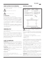
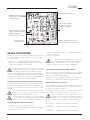
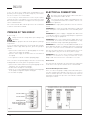
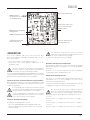
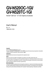
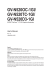
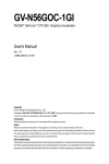
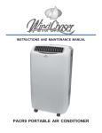
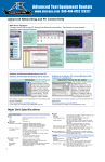
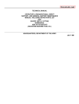
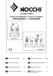
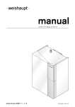
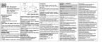
EASYBOOST
GRUPPI DI PRESSIONE CON 2 POMPE
BOOSTER SETS WITH 2 PUMPS
253PB090-10-1407
IT
Originale Istruzioni per l‘uso
EN
Instruction Manual
www.pentair.com
2
ITALIANO
INDICAZIONI DI SICUREZZA
INSTALLAZIONE
Prestare particolare attenzione alle diciture contrassegnate
con la seguente simbologia.
Schema di installazione normalmente utilizzato.
Pericolo generico per le persone
Pericolo tensione elettrica
ATTENZIONE!
Pericolo per macchinari e funzionamento
Il presente apparecchio può essere utilizzato da bambini a
partire da 8 anni e da persone con disabilità fisiche, sensoriali
o mentali o carenza di esperienza e conoscenze, se sottoposti
alla supervisione o sono state istruite sull'uso dell'apparecchio e ne hanno compreso i pericoli risultanti. Ai bambini non
è consentito giocare con l'apparecchio. La pulizia e la manutenzione dell'utente non può essere eseguita da bambini
senza supervisione.
Prima di procedere all'installazione, leggere attentamente il
contenuto del presente manuale. I danni provocati dal mancato rispetto delle indicazioni riportate non potranno essere
coperti dalla garanzia.
GENERALITA’
I nostri gruppi di pressurizzazione sono costruiti per il pompaggio di acqua pulita.
Devono essere installati in locali protetti dalle intemperie e
dal gelo, ben aerati e in atmosfera non pericolosa. Ogni nostro
gruppo è collaudato in tutte le sue parti nei nostri stabilimenti.
Al momento della consegna verificare che il gruppo non abbia
subito danni durante il trasporto; in tal caso avvertire immediatamente il rivenditore. In ogni caso entro e non oltre dieci
giorni dalla data di acquisto.
LIMITI D'IMPIEGO
ATTENZIONE: prima di procedere al controllo dell’adescamento delle pompe, verificare che la loro pressione massima,
riportata sulla targa delle pompe stesse, sia compatibile con
la pressione sopportata dall’impianto e dalle sue apparecchiature e che eventuali valvole di sicurezza abbiano un valore di intervento superiore a quello della pressione massima
delle pompe.
ATTENZIONE! Il gruppo non è adatto al pompaggio di liquidi
chimicamente aggressivi o infiammabili.
ATTENZIONE! Evitare tassativamente il funzionamento a secco delle elettropompe.
Temperatura
Massima temperatura del liquido pompato: 40°C
Massima temperatura ambiente: 40°C, (50°C per le elettropompe DHR, VLR)
Fig. 1
Tutte le operazioni relative alla installazione devono
essere effettuate con gruppo scollegato dalla rete di
alimentazione.
Nel caso che il gruppo dì pressurizzazione venga alimentato
da pozzo, per evitare che si verifichino fenomeni di disadescamento, si consiglia di controllare i dati caratteristici dello
stesso:
- Livello statico ( livello iniziale dei pozzo )
- Livello dinamico ( livello raggiunto durante il funzionamento dei gruppo)
- Portata
- Hmax aspirazione
Per ridurre le perdite di carico è necessario installare il gruppo il più vicino possibile al punto di prelievo e predisporre una
tubazione d'aspirazione con il minor numero possibile di curve che dovranno essere in ogni caso ad ampio raggio.
Anche il diametro della tubazione dovrà essere calcolato in
modo da ridurre al minimo le perdite di carico per cui è necessaria una dimensione maggiore o uguale a quella delle
bocche di aspirazione delle pompe.
Per evitare la formazione di sacche d'aria nelle tubazioni
d'aspirazione è necessario che queste abbiano sempre una
pendenza positiva, dal basso verso l'alto, evitando contropendenze o "colli d'oca”, e che nei collegamenti non vi siano infiltrazioni d'aria.
Collegare il collettore di mandata del gruppo al collettore di
distribuzione interponendo un giunto antivibrante. Questo
collegamento può essere effettuato sia dal lato destro o sinistro del collettore spostando la calotta filettata.
ATTENZIONE! E' buona norma prevedere lo smaltimento di
perdite di acqua provenienti dalla eventuale cattiva tenuta di
guarnizioni, tenute meccaniche, tracimazione di serbatoi, ecc.
3
ITALIANO
Nel caso che nelle immediate vicinanze dei gruppo, sulla tubazione di mandata, non ci siano punti di prelievo consigliamo
l'installazione di un rubinetto di prova.
COLLEGAMENTI ELETTRICI
L’alimentazione del quadro deve prevedere un dispositivo differenziale con corrente di intervento non superiore a 30 mA.
E’ necessario controllare periodicamente la pressione di precarica dei vasi a membrana che deve risultare 0,2 ÷ 0,3 BAR
inferiore alla pressione minima di chiusura del pressostato
tarato più basso.
Detto controllo deve essere effettuato in assenza di pressione
nell’impianto o a serbatoi smontati.
ADESCAMENTO DEL GRUPPO
Riferirsi alla Fig.1
Operare sempre con l’alimentazione elettrica disinserita.
ATTENZIONE! Prima di mettere in funzione il gruppo è necessario provvedere al suo riempimento.
Nel caso di aspirazione con battente positivo, deposito fuori
terra, acquedotto o condotta in pressione, provvedere all'adescamento del gruppo come segue:
∙∙ aprire tutte le valvole e togliere i tappi di carico sia sul collettore di aspirazione che sulle pompe;
∙∙ aprire la valvola di intercettazione dell’alimentazione idrica
sino alla fuoriuscita dell'acqua;
∙∙ richiudere il rubinetto di alimentazione ed i tappi di carico.
Nel caso che l'alimentazione del gruppo sia con battente negativo, pozzo o serbatoio interrato, provvedere all'ade-scamento del gruppo come segue:
∙∙ aprire tutte le valvole e togliere i tappi di carico sulle pompe
e sul collettore d'aspirazione;
∙∙ effettuare il riempimento d'acqua attraverso la tubazione
d'aspirazione;
∙∙ effettuare i rabbocchi necessari attraverso i tappi di carico
sui corpi pompa fino al riempimento completo;
∙∙ rimontare i tappi.
Accertarsi che l’alimentazione elettrica sia provvista
di un efficiente impianto di terra secondo le vigenti
normative.
ATTENZIONE! Nel quadro monofase standard, non è previsto
un interruttore generale.
ATTENZIONE! Accertarsi che la tensione e la frequenza di targa corrispondano a quelle di alimentazione disponibile.
ATTENZIONE! L'impianto di alimentazione elettrica deve essere dotato di un interruttore magnetotermico differenziale
con sensibilità richiesta dalla normativa per il tipo di installazione.
ATTENZIONE! Prima di collegare il cavo d'alimentazione al
quadro di comando, assicurarsi che il suo dimensionato sia
sufficiente per sopportare la corrente massima richiesta dalle
pompe del gruppo.
ATTENZIONE! Il collegamento dei quadri elettrici alla rete di
alimentazione deve essere effettuato seguendo le indicazioni
riportate sullo schema dei collegamenti elettrici contenuti nel
quadro di comando.
I nostri gruppi vengono consegnati con i morsetti "LIV" ponticellati (L1-L2 per il quadro Monofase, Fig.2; 5-6 per il quadro
Trifase, Fig.3).
ATTENTIONE! In questo caso il gruppo non è protetto contro il
funzionamento a secco. E’ quindi necessario rimuovere i ponti
elettrici e collegarvi il dispositivo di controllo prescelto.
Tramite interruttore a galleggiante
Il galleggiante deve essere installato nella vasca collegato con
due conduttori agli appositi morsetti del quadro di comando.
Tramite un pressostato di minima inverso
Nel caso in cui il gruppo venga alimentato da una condotta
idrica in pressione ( ad esempio acquedotto comunale ) è necessario installare un pressostato di minima pressione che
interdica il funzionamento del gruppo se la pressione nella
condotta scende al di sotto del valore prestabilito.
Pressostato 1
Pressostato 2
Protezione Marcia a secco
Tagliare I ponticelli per
il collegamento agli altri
apparecchi di controllo
Fig. 2
4
Fig. 3
ITALIANO
Quadro Elettrico Monofase
Pompa 2, 1x230V
Pompa 1, 1x230V
Contatti BMS (Building
Management System)
Morsettiera
Dispositivi Esterni
Scheda EB1
LED di sistema
BMS LEDs
Porta fusibili
Trim di regolazione
Temporizzazione 0-180’’
Connettori
Alimentazione 230V
& Contatto di Terra
Connettori di uscita
Pompa 1 (M1) & Pompa 2 (M2)
Fig. 4
AUT Spia Verde Seganlazione Automatico
MAN Spia Rossa Segnalazione Manuale
LINE Spia Verde Segnalazione Presenza Rete
Spia Verde
Segnalazione
Pompa 1/2 in Moto
Pulsante MAN/AUT
Pulsante ON/OFF Pompa 1/2
5
ITALIANO
Quadro Elettrico Trifase
SCHEDA EB3
Fig. 5
Hydraulic fault = Spia Rossa
segnalazione basso livello acqua
vasca
Electric fault = Spia Rossa
segnalazione blocco termico
Line = Spia Verde Segnalazione
Presenza Rete
AUT - Spia Verde Seganlazione Automatico
MAN - Spia Rossa Segnalazione Manuale
AUT/MAN = Pulsante
Automatico/Manuale
Spia Verde Segnalazione
Pompa in Moto
Pulsante ON/OFF pompa 1/2
6
ITALIANO
Contatti BMS (con fusibile)
S1-S2 Commutatore
Impostazione assorbimento
elettropompa 1 e 2
Connettore per comandi
elettropompe, controllo
pressostati ed assorbimenti
S3 Communtatore Configurazione modalità di lavoro
Trim di regolazione
Temporizzazione 0-180''
Comunicazioni e
Funzioni avanzate
Fusibile di comando contattori F1
Fusibile di alimentazione scheda F2
Fig. 6
MESSA IN FUNZIONE
Una volta effettuati tutti i collegamenti idraulici ed elettrici ed
il riempimento idraulico delle pompe e dei collettori, procedere come segue:
∙∙ chiudere tutte le valvole dell'impianto di distribuzione.
∙∙ aprire tutte le valvole del gruppo, comprese quelle dell’ autoclave a membrana o a cuscino d’aria.
Da questo momento tutte le operazioni sui conduttori
delle pompe dei pressostati, ecc. devono essere effettuate dopo aver tolto tensione la quadro elettrico.
Premere il tasto [AUT/MAN] e predisporre il gruppo al funzionamento in MANUALE e successivamente premere il pulsante [ON/OFF] della pompa interessata mettendola in funzione.
Verificare il senso di rotazione dell’elettropompe.
Controllo del senso di rotazione solo per pompe trifase
Per ogni pompa: Dopo avere avviato l’elettropompa, premere
nuovamente il tasto [ON/OFF] per arrestare la pompa e controllarne il senso di rotazione. Effettuare l’operazione su tutte
le pompe.
Se le due pompe hanno il senso di rotazione invertito:
Togliere tensione generale ed invertire due fasi del
cavo di alimentazione del quadro elettrico.
Se solo una delle due pompe ha il senso di rotazione
contrario: Riferirsi alla figura della tastiera ed agli
schemi elettrici inseriti nel quadro di comando.
Controllo dell’adescamento delle pompe
Mantenendo le valvole di tutti i prelievi chiuse:
∙∙ Premere il pulsante [AUT/MAN] per impostare il gruppo in
funzionamento manuale.
∙∙ Avviare una pompa e verificare il raggiungimento della
pressione massima
∙∙ Arrestare la pompa
Nel caso non si dovesse raggiungere la pressione massima, effettuare di nuovo le operazioni di riempimento
del collettore di aspirazione sino al corpo pompa.
∙∙ Ripetere l’operazione sulla seconda elettropompa
Avviamento in automatico del gruppo standard
Dopo aver portato in pressione il gruppo attraverso l’azionamento manuale delle pompe, premere il tasto [AUT/MAN] e
posizionare in modalità AUTOMATICO.
Da questo momento il gruppo funzionerà automaticamente
sulla base della quantità di acqua prelevata dall’utenza.
Modifica della pressione di lavoro
I nostri gruppi sono collaudati e tarati in fabbrica e la pressione di lavoro viene impostata in funzione della curva caratteristica delle elettropompe utilizzate.
E’ comunque possibile modificare i valori della pressione di
lavoro variando la taratura dei pressostati utilizzati.
I valori di taratura dei pressostati devono essere
compresi tra il valori di minima e di massima pressione di lavoro prevista per le pompe utilizzate nel
gruppo e riportate sulla targa applicata sulle pompe stesse.
∙∙ Ciclo 1
Pressostato 1 -> Pompa 1 | Pressostato 2 -> Pompa 2
∙∙ Ciclo 2
Pressostato 1 -> Pompa 2 | Pressostato 2 -> Pompa 1
∙∙ Ciclo 3
Pressostato 1 -> Pompa 1 | Pressostato 2 -> Pompa 2
7
ITALIANO
La rotazione automatica delle pompe avviene anche se si avvia una sola pompa.
∙∙ Ciclo 1: Pressostato 1 -> Pompa 1
∙∙ Ciclo 2: Pressostato 1 -> Pompa 2
S3=0000:1 duty - 1 assist ciclico (configurazione standard)
S3
POS
1
0
ATTENZIONE! Per una corretta taratura dei pressostati eseguire le operazione seguendo esattamente la sequenza sottoindicata.
ATTENZIONE! Per una corretta taratura eseguire le operazione seguendo esattamente la sequenza indicata nel paragrafo
relativo alla taratura dei pressostati e verificare la compatibilità con la precarica dei vasi.
Avviamento personalizzato in automatico del gruppo
Operare sempre con l’alimentazione elettrica disinserita.
Pin
1
2
3
4
S3=0100: 1 duty - 1 assist non ciclico
S3
POS
1
0
Pin
1
2
3
4
S3=0010: 1 duty - 1 standby ciclico
S3
POS
1
0
Pin
Versione monofase
Nella configurazione standard (ponticelli JMP2 e JMP3 scollegati) il gruppo funziona in maniera ciclica (1duty – 1 assist).
Agendo sui ponticelli di configurazione JMP2 e JMP3 presenti
sulla scheda è possibile modificare la modalità di lavoro.
JMP2 collegato: modalità 1 duty – 1 standby: in questo caso
verrà attivata una sola elettropompa in modo ciclico (salvo
caso di allarme o rimozione di un’elettropompa). L’elettropompa di riserva verrà attivata solo in caso di allarme elettrico della prima elettropompa o al ciclo successivo.
JMP3 collegato: elettropompa 2 esclusa. Quest’ultima configurazione può essere utilizzata ad esempio nel caso di manutenzione o se necessario scollegare un’elettropompa dal
gruppo.
1
2
3
4
S3=0110: 1 duty - 1 standby non ciclico
S3
POS
1
0
Pin
1
S3=0001
2
3
4
1 duty – 1 assist ciclico
Riarmo allarme elettrico temporizzato: Dopo 5 minuti per tre
volte il sistema prova a riavviare la/e elettropompa/e in condizione di allarme elettrico.
S3
POS
1
Nota: i ponticelli devono essere collegati quando il quadro
elettrico non è alimentato.
0
Pin
Versione trifase
Nella configurazione standard il gruppo funziona in maniera
ciclica (1duty – 1 assist). Modificando le posizioni dei contatti del selettore S3, posizionato nella parte posteriore della
scheda, è possibile modifi-care le modalità di lavoro.
S3
1
S3=1000
2
3
4
1 duty – 1 assist ciclico
Configurazione avanzata (service): Nota: questa configurazione disabilita il normale funzionamento del gruppo.
S3
POS
1
POS
0
1
0
Pin
1
2
3
4
Il pin 4 la temporizzazione automatica nel riarmo allarme
(0: non attivo, 1: attivo).
Il pin 3 determina la modalità (0: seconda pompa elettropompa assist, 1: seconda elettropompa standby)
Il pin 2 ciclicità (0: ciclo attivo – 1: ciclo non attivo)
Il pin 1 determina la modalità di controllo avanzato (comunicazione/service).
8
Pin
1
2
3
4
ITALIANO
Taratura pressostati
Taratura dei pressostati mod. XMP 12
Taratura dei pressostati mod. PY06
Fig. 7
∙∙ Avvitare la vite A del pressostato quasi totalmente
∙∙ Allentare la vite B del pressostato quasi totalmente
∙∙ Chiudere tutti i punti di prelievo e portare l’impianto alla
massima pressione facendo funzionare una pompa in manuale. Arrestare la pompa.
∙∙ Lasciare il quadro elettrico predisposto per il funzionamento in manuale.
∙∙ Aprire un prelievo e chiuderlo quando la pressione di rete
ha raggiunto il valore di avvio che intendiamo attribuire alla
prima pompa.
∙∙ Serrare la vite B del pressostato N. 1 sino a quando il suo
contatto elettrico chiude.
∙∙ Facendo funzionare una pompa manualmente, innalzare la
pressione di rete portandola al valore di arresto che vogliamo attribuire alla prima pompa.
∙∙ Allentare la vite A sino a quando il pressostato N. 1 apre.
Ripetere l’operazione sull’altro pressostato.
Taratura dei pressostati mod. PM/5 e PM12
Fig. 9
∙∙ Avvitare la vite A del pressostato circa a metà posizione.
∙∙ Avvitare la vite B del pressostato circa a metà posizione.
∙∙ Chiudere tutti i punti di prelievo e, con una pompa funzionante in manuale, portare lentamente la pressione del collettore di mandata al valore di apertura (arresto pompa)
che vogliamo attribuire al pressostato n.1 (il contatto del
pressostato rimanere deve essere chiuso – ON -- )
∙∙ Allentare la vite B del pressostato N. 1 sino a quando il suo
contatto elettrico apre (OFF).
∙∙ Aprire un piccolo prelievo e portare lentamente la pressione di rete al valore di chiusura (avvio pompa)che vogliamo
attribuire al pressostato n.1.
∙∙ Allentare la vite A sino a quando il pressostato N. 1 chiude.
Ripetere l’operazione sull’altro pressostato
ATTIVAZIONE TEMPORIZZAZIONE
ELETTROPOMPE
La temporizzazione inizia dall’istante in cui il pressostato apre
i suoi contatti. La temporizzazione è attiva solo in modalità
AUTOMATICO [AUT].
ATTENZIONE! Con la temporizzazione attivata, le pompe possono raggiungere la loro pressione massima. Verificare che
questa pressione non sia dannosa per l’impianto, la rete di
distribuzione o le apparecchiature utilizzatrici.
Agendo sul potenziometro della pompa interessata si può inserire e disinserire la temporizzazione delle pompe.
Fig. 8
∙∙ Avvitare la vite A del pressostato circa a metà posizione.
Allentare la vite B del pressostato.
∙∙ Chiudere tutti i punti di prelievo e, con una pompa funzionante in manuale, portare lentamente la pressione del collettore di mandata sino a raggiungere l’apertura del contatto del pressostato (OFF).
∙∙ Aprire un piccolo prelievo portando la pressione al valore
di chiusura (avvio pompa) che vogliamo attribuire al pressostato n.1
∙∙ Stringere la vite B del pressostato N. 1 sino a quando il suo
contatto elettrico chiude (ON).
∙∙ Con una pompa funzionante in manuale portare lentamente la pressione di rete al valore di apertura (arresto pompa)
che vogliamo attribuire alla prima pompa. Allentare la vite
A sino a quando il pressostato N. 1 apre. Ripetere l’operazione sull’altro pressostato.
Per pompe monofasi
La scheda elettronica prevede la possibilità
di temporizzare il funzionamento delle due
pompe da un minimo di 3” sino ad un massimo di circa 180”.
Ruotando verso destra i potenziometri P1 e P2 il tempo di
spegnimento aumenta.
Per pompe trifasi
di circa 180”.
La scheda elettronica prevede la possibilità
di temporizzare lo spegnimento dell’ultima
pompa in funzionamento che si arresta con
un ritardo rispetto al comando del pressostato da un minimo di 3” sino ad un massimo
9
ITALIANO
Ruotando verso destra il potenziometro T1, accessibile all’interno del quadro sulla scheda di controllo, il tempo aumenta.
Operare sempre con l’alimentazione elettrica disinserita.
ANOMALIE DI FUNZIONAMENTO
Le pompe non si avviano
Tutte le spie sono spente
∙∙ Manca l'alimentazione elettrica al quadro = Alimentare il
quadro elettrico
∙∙ I fusibili di alimentazione o di uscita del trasformatore (versione trifase) sono interrotti = Sostituire i fusibili interrotti
Spia linea (LINE) accesa, - Spia configurazione (MAN) accesa
∙∙ Il gruppo è predisposto per il funzionamento Manuale = Attivare funzionamento in automatico premendo il pulsante
[AUT/MAN]
Spia linea (LINE) accesa, - Spia livello (B.LIV) o (HYDRAULIC FAULT) accesa
∙∙ Manca acqua nel serbatoio di prima raccolta = Ripristinare
il livello dell'acqua
∙∙ Il controllo di livello è disinserito o guasto = Installare il
controllo di livello o sostituirlo
∙∙ In mancanza di controllo livello, il ponticello è scollegato =
Verificare il ponticello
Spia linea (LINE) accesa, - Spia automatica (AUT) accesa Spia marcia pompa/e accesa/e
∙∙ I fusibili di una o delle due pompe sono interrotti = Sostituire i fusibili della/e pompa/e
Spia linea (LINE) accesa, - Spia automatica (AUT) accesa, Spia ELECTRIC FAULT accesa
∙∙ Condizione di sovraccarico o mancato assorbimento di una
o entrambe le elettropompe = Verificare il corretto funzionamento delle pompe in condizione manuale. Qualora
funzionino, riconfigurare in automatico. In caso contrario
contattare il centro assistenza.
Spia linea (LINE) accesa, - Spia automatica (AUT) accesa, Spia marcia pompa/e spenta/e
∙∙ I pressostati sono starati, scollegati o guasti = Controllare i
pressostati ed i loro collegamenti
10
Le pompe non si arrestano
Spia linea (LINE) accesa, Spia marcia pompa/e accesa/e
∙∙ Le pompe funzionano in configurazione manuale = Attivare
funzionamento in automatico premendo il pulsante [AUT/
MAN]
∙∙ Uno o entrambi i pressostati hanno il contatto chiuso per
difetto di taratura = Tarare corretamente i pressostati
∙∙ La linea pressostati è ostruito = Eliminare l'ostruzione
∙∙ Il cavo dei pressostati è in corto circuito = Verificare le connessioni elettriche dei pressostati
∙∙ Le valvole di ritegno sono sporche o guaste = Pulire o sostituire le valvole
∙∙ La temporizzazione delle pompe è attivata = Portare a il
tempo minimo di lavoro
Le pompe non raggiungono la pressione di
targa
Spia linea (LINE) accesa, - Spia marcia pompa/e accesa/e
∙∙ Valvole di ritegno parzialmente ostruite = Pulire le valvole
∙∙ Valvola di intercettazione socchiusa o ostruita = Aprire totalmente o pulire le valvole
∙∙ Rotazione inversa della pompa = Invertire il senso di rotazione dei motori (caso gruppo trifase)
∙∙ Pompa disinnescata = Togliere eventuali sacche d'aria nel
collettore di aspirazione o nella pompa
ENGLISH
SAFETY INSTRUCTIONS
INSTALLATION
Pay particular attention to the signs and their symbols
Assembly diagrams normally used
General danger to people
Warning of electrical voltage
ATTENTION!
Danger to equipment and operation
This appliance can be used by children aged 8 years or over
and by persons with limited physical, sensory or intellectual
capabilities, or with limited experience and knowledge, provided that they are supervised or have been instructed in the
safe use of the appliance and are aware of the dangers involved. Children must not be allowed to play with the appliance. Cleaning and user maintenance must not be carried out
by children unless they are supervised.
Before assembling, carefully read the contents of this manual. The non-observance of the instructions will result in the
annulment of the warranty.
Fig. 1
GENERAL INFORMATION
Our pressurization groups are manufactured for pumping
clean water. They must be installed in places protected from
bad weather and ice, well ventilated and in non-dangerous
environment.
Each of our groups is entirely tested in our establishments.
Upon delivery, check that the group has not suffered any damage during transportation; in this case, contact immediately
the retailer. In case of claims, contact immediately the retailer
within ten days of purchase.
LIMIT OF USE
ATTENTION! Before checking the pumps priming make sure
that their max. pressure, shown on their nameplate, is compatible both with the system pressure and with its devices.
Furthermore make sure that eventual security valves are set
to have an higher intervene pressure than the max. pressure
of the pumps.
ATTENTION! The group is not suitable for pumping chemically aggressive or flammable liquids.
ATTENTION! Avoid any dry-operating of the motor pump.
Temperature
Maximum temperature of the pumped liquid: 40°C
Maximum ambient temperature: 40°C, (50°C per le elettropompe DHR, VLR)
All the assembly operations must be carried out
withgroup disconnected from the power grid.
In the case where the pressurization group is fed by a tank,
avoid any unpriming phenomena; we recommend to control
the following characteristic data:
- Static level (initial level of the well)
- Dynamic level (level reached during the group operation)
- Flow rate
- Hmax suction
To reduce losses during replenishment it is necessary to install the group as close as possible to the pumping point and
to install a suction pipe with a minor number of curvatures
that should have a sufficiently wide radius.
Even the diameter of the pipe should be calculated so as to
reduce load losses, what requires dimensions greater than or
equal to those of the pump aspiration inlet.
In order to avoid the formation of air locks into the suction
pipes, these ones must have a positive gradient, from bottom
to top, avoiding counter gradients or “goosenecks”, and there
must not any air infiltration in the connections.
Connect the delivery collector to the distribution collector by
interposing vibration-damping joint. This connection can be
done either on the right side or on the left side of the collector
by displacing the blind flange or the threaded cover.
ATTENTION! It is a good rule to foresee the evacuation of water losses in case of bad seal of joints, mechanical seal, tanks
overflowing, etc.
11
ENGLISH
In the case where there would not be any pumping in close
proximity from the group, on the discharge line, the installation of a test faucet is recommended.
ELECTRICal CONNECTION
The panel must be powered by a differential device
with on/off power under 30 mA.
It is necessary to control from time to time the pre-replenishment pressure of membrane vessel that must be 0.2÷0.3
bar lower than the minimum closing pressure of the pressure
switch calibrated lower.
This control must be done without pressure in the installation
or with the tanks disassembled.
PRIMING OF THE GROUP
Refers to Fig. 1
Always shut off the voltage before proceeding to any
operation.
ATTENTION! The group needs to be filled up before putting it
in operation.
In case of aspiration with positive suction head, open storage,
aqueduct or water pipe under pressure, prime the group as
follows:
∙∙ open all valves and remove the priming plugs on the aspiration collector and on the pumps;
∙∙ open the water supply on-off valve until the evacuation of
the liquid;
∙∙ close again the feed faucet and the pumping plugs.
In the case where the group supply is with lower suction head,
underground well or tank, prime the group as follows:
∙∙ open all valves and to and remove the priming plugs on the
aspiration collector and on the pumps;
∙∙ fill with water through the suction pipe;
∙∙ make the necessary topping-up through the priming plugs
on the pump casing until complete filling-up
∙∙ re-assemble the plugs.
Check that the power supply is provided with an efficient ground installation in accordance with the current regulations.
ATTENTION! The single-phase panel does not have a master
switch.
ATTENTION! Check that the voltage and frequency indicated
on the nameplate correspond to those of the available power
grid.
ATTENTION! The power supply is equipped with differential
circuit breaker with the sensitivity required by the regulations
in force for this type of equipment.
ATTENTION! Before connecting the power supply cable to the
control board, check that it has sufficient dimensions to support the maximum voltage required by group pumps.
ATTENTION! The connection of the distribution boards to the
power grid must be done according to indications reported on
the electric connection scheme situated in the control board.
Our units are delivered with "LIV" jump terminals (L1-L2 for
the single-phase, Fig.1; 5-6 for the three-phases, Fig.2).
ATTENTION! In this case the unit is not protected against dry
operation. It is therefore necessary to remove the electric
bridges and connect them to the control device selected.
Float switch
The float must be installed in the tank and connected thanks
to two wires to the special terminals on the control board.
Inverted minimal pressure sensor
In the case where the group is fed by a water duct under pressure (for example municipal water system), it is necessary to
install a minimal pressure sensor which prevents from the
working of the group if the pressure in the duct descends below the preset value.
Pressure switch 1
Pressure switch 2
Run dry protection
Cut the electric bridges and
connect them to the control
device selected
Fig. 3
Fig. 2
12
ENGLISH
Single-phase unit
Pump 2, 1x230V
Pump 1, 1x230V
BMS contacts (Building
Management System)
External device
terminal board
EB1 board
BMS LEDs
System LEDs
0-180’’ Timing adjustment
Fuses
Output connectors
Pump 1 (M1) & Pump 2 (M2)
Input connectors
230V line & Ground
terminal board
Fig. 4
AUT Green light for automatic mode
MAN Red light for manual mode
LINE Green light for power on
Green lights for
running pump1 and
pump2
Switch MAN/AUT
Switch ON/OFF Pump 1/2
13
ENGLISH
Three-phase unit
BOARD EB3
Fig. 5
Hydraulic fault = Red light
low level water tank
Electric fault = Red light for
thermical block
Line = Green light for power on
AUT - Green light for automatic mode
MAN - Red light for manual mode
AUT/MAN = Switch Automatic/
Manual
Green light for running pump
ON/OFF buttons
14
ENGLISH
BMS contacts (with fuse)
S1-S2 Dipswitch
setting current for overload
cut off pump1 and 2
Pump control connectors,
pressure switch and absorption control
S3 Dipswitch Configuring
working mode
0-180'' timing adjustment
Communications and
Advanced Features
Contactor control fuse F1
Power board fuse F2
Fig. 6
Operation
Once all the hydraulic and electric connections have been
done for the hydraulic priming of the pumps and collectors,
proceed as follows:
∙∙ close all the valves of the distribution system
∙∙ open all the valves of the group, included those of the
membrane ways
From this moment any operations on pump ducts,
pressure sensor, etc. must be done after having cut
the voltage off from the distribution board.
Press the [AUT/MAN] pushbutton for MANUAL start and subsequently push the [ON/OFF] pushbutton to start the desired
pump. Verify the rotational direction of the pumps.
Check the direction of rotation (only three-phase pumps)
After starting the pump, press the [ON / OFF] button to stop
the pump and check the direction of rotation. Perform the operation on all pumps.
If the two pumps have the direction of rotation reversed:
Disconnect the power supply and invert two phases of
the general power cable from the electrical panel.
If only one pump has the wrong direction of rotation:
Remove power and reverse the wires in the terminals
of the contactor power for that pump.
Check the priming of the pumps
Keeping all the drawing valves closed:
∙∙ Press the [AUT/MAN] button for MANUAL mode start
∙∙ Start one pump and verify that max pressure is reached
∙∙ Stop the pump
Check that the circuit pressure reaches the maximum value. If not, repeat the filling operations of the
collection of aspiration to the pump.
∙∙ Repeat the operation on the other pump
Automatic Starting of the standard unit
After having forced pressure into the unit through the manual
driving of the pump, set the pump selectors to the AUTOMATIC position.
From then on, the unit will automatically work according to
the quantity of water withdrawn by its use.
Change of the working pressure
Our units are set and tested during manufacture and the
working pressure is set up according to the characteristic
curve of the motor pumps used.
It is however possible to modify the working pressure value by
changing the setting of the pressure switch used.
The values of pressure switch calibrations must be
between the minimum and maximum working pressure levels foreseen for the pump used in the unit
and reported on the plate applied to the pumps themselves.
∙∙ Cycle 1
Pressure switch 1 -> Pump1 | Pressure switch 2 -> Pump 2
∙∙ Cycle 2
Pressure switch 1 -> Pump 2 | Pressure switch 2 -> Pump 1
∙∙ Cycle 3
Pressure switch 1 -> Pump 1 | Pressure switch 2 -> Pump 2
15
ENGLISH
Automatic rotation of the pumps is carried out also if only one
pump starts.
∙∙ Cycle 1: Pressure switch 1 -> Pump 1
∙∙ Cycle 2: Pressure switch 1 -> Pump 2
S3=0000: 1 duty - 1 cycle assist (standard configuration)
S3
POS
1
0
ATTENTION! For correct calibration of the pressure switches
the following operations must be carried out exactly in the sequence reported.
ATTENTION! For correct calibration of the pressure switches
the following operations must be carried out exactly in the sequence reported.
Pin
Always shut off the voltage before proceeding to any
operation.
2
3
4
S3=0100: 1 duty - 1 non cycle assist (standard configuration)
S3
POS
1
0
Pin
Customized automatic starting of the booster
1
1
2
3
4
S3=0010: 1 duty - 1 cycle standby
S3
POS
1
Single-phase version
0
In the standard configuration (jumpers JMP2 and JMP3 disconnected) the group operates in a cyclical manner (1duty - 1
assist). Acting on the configuration jumpers JMP2 and JMP3
on the card it is possible to modify the working mode.
JMP2 connected: Mode 1 duty - 1 standby: in this case one
pump will be activated in a cyclic manner (except in case of
alarm or removal of an electric pump). The reserve pump will
be activated only in the event of an alarm or electric pump
before the next cycle.
JMP3 connected: second electric pumpd excluded. This configuration can be used for example in the case of maintenance
or if necessary to disconnect an electric pump from the group.
Note: The jumpers must be connected when the electric power is off.
Pin
1
2
3
4
S3=0110: 1 duty - 1 non cycle standby
S3
POS
1
0
Pin
1
S3=0001
2
3
4
1 duty – 1 cycle assist
Rearming the electric timing alarm: After 5 minutes, the system will try three times to restart the electric pump under
electric alarm condition.
S3
POS
Three-phase version
1
In the standard configuration, the group operates in a cyclical
manner (1duty - 1 assist). By changing the positions of the
contacts of the switch S3, located at the back of the card, it is
possible to modify the working mode.
0
S3
POS
1
0
Pin
1
2
3
1
S3=1000
2
3
4
1 duty – 1 cycle assist
Advanced configuration (service): Note: this configuration disables the normal operation of the group.
S3
POS
1
4
Pin 4 timing in automatic reset alarm (0: not active, 1: active).
Pin 3 determines the mode (0: second pump assists, 1: second pump standby)
Pin 2 cycles (0: active cycle - 1: cycle is not active)
Pin 1 determines the advanced control mode (communication
/ service).
16
Pin
0
Pin
1
2
3
4
ENGLISH
Pressure switches calibration
Calibration of the pressure switches mod. XMP 12
Calibration of the pressure switches mod. PY06
Fig. 9
Fig. 7
∙∙ Tighten almost to the maximum screw A of the pressure
switch
∙∙ Unscrew almost totally screw B of the pressure switch
∙∙ Close all the points of collection and bring the plant to
the maximum pressure by manual use of pump. Stop the
pump.
∙∙ Leave the switchboard predisposed for MANUAL operation.
∙∙ Open a point of collection and close it when the circuit
pressure has reached the level which we intend to assign
to the first pump.
∙∙ Tighten screw B of the pressure switch n.1 to the point
where its electric contact closes.
∙∙ Manually use the pump to raise the network pressure and
bring it to the level that we want to assign to the first pump.
∙∙ Unscrew screw A to the point where the pressure switch n.
1 is opened.
∙∙ Repeat the operation on the other pressure switch.
Calibration of the pressure switches mod. PM/5 e PM12
∙∙ Tighten screw A of the pressure switch to half-way position.
∙∙ Tighten screw B of the pressure switch to half-way position.
∙∙ Close all the connection points and with a pump in MANUAL mode, slowly bring the collector discharge pressure to
the opening level (stop/arrest pump) that we want to assign
to pressure switch n.1 (the pressure switch contact must
be closed - ON -)
∙∙ Unscrew screw B of pressure switch n. 1 to the point where
its electric contact opens (OFF).
∙∙ Open a small collection/connection and slowly bring the
circuit pressure to the closing level (start pump) that we
want to assign to pressure switch n. 1
∙∙ Unscrew screw A to the point where pressure switch n.1
closes.
∙∙ Repeat the operation on the other pressure switch.
ACTIVATION OF ELECTROPUMP
TEMPORIzATION
Temporization begins from the moment in which the thrust
meter opens its contacts. Temporization is activated only in
AUTOMATIC [AUT] mode.
ATTENTION! With temporization activated, the pumps can
reach their maximum pressure. Check that this pressure is
not harmful to the system, the distribution system or the devices.
Acting on the potentiometer of the desired pump, you can activate and inactivate the temporization of the pumps
Fig. 8
∙∙ Tighten screw A of the pressure switch to half-way position.
∙∙ Unscrew screw B of the pressure switch.
∙∙ Close all the collection points and with a pump in MANUAL
mode, slowly bring the discharge collector pressure up to
reach the opening of the pressure switch contact (OFF).
∙∙ Open a small collector by bringing the pressure to the level
(start pump) that we want to assign to pressure switch n.1
∙∙ Tighten screw B of pressure switch n.1 to the point where
its electric contact closes (ON).
∙∙ With a pump in MANUAL mode, slowly bring the circuit
pressure to the starting level (arrest pump) that we want to
assign to the first pump.
∙∙ Unscrew screw A to the point where pressure switch n. 1
opens.
Always shut off the voltage before proceeding to any
operation.
Single-phase pumps
The electronic card foresees the possibility
of temporizing the functioning of the two
pumps from a minimum of 3’’ up to a maximum of 180’’.
Rotating potentiometers P1 and P2 towards right, the switching-off time increases.
17
ENGLISH
Three-phases pumps
The electronic card foresees the possibility of
temporizing a delayed switching-off of the
last running pump subordinate to the pressure switch input, with a delay of a minimum
3’’ up to a maximum of 180’’.
Rotating the potentiometer T1 towards right, accessible on
the control board inside the control panel, the switching-off
time increases.
FUNCTIONING ANOMALIES
The pumps do not start
All the pilot lights are off
∙∙ No power supply at the distribution board = Supply power to
the distribution board
∙∙ The supply or the exit fuses of the transformer (three-phases version) are disconnected = Replace the disconnected
LINE pilot light and MAN pilot light are on
∙∙ The group is set to manual mode = Activate the AUTOMATIC mode pressing the [AUT/MAN] pushbutton
LINE pilot light on, B.LIV or HYDRAULIC FAULT pilot light
on
∙∙ Lack of water in the first collection tank = Restore the water level
∙∙ The level control is not operating or is damaged = Install or
replace the level control
∙∙ The level control is not operating due to the disconnected
bridge = Verify the bridge
LINE pilot light on; AUT pilot light on; Running pump pilot
light(s) on
∙∙ The fuses of one or more motor pumps are disconnected =
Replace the fuses of the motor pump(s)
LINE pilot light on; AUT pilot light on; ELECTRIC FAULT pilot
light on
∙∙ Overload or missing electrical absorption of one or more
motor pumps = Verify the correct MANUAL mode selection.
In case the pumps are working, reactivate the AUTOMATIC
mode. On the contrary, contact the service center.
LINE pilot light on; AUT pilot light on; Running pump pilot
light(s) off
∙∙ The pressure switches are not calibrated, disconnected or
damaged = Control the pressure switches and their connections
The motorpumps do not stop
LINE pilot light on; Running pump pilot light(s) on
∙∙ The pump(s) operate in MANUAL mode = Activate the AUTOMATIC mode pressing the [AUT/MAN] pushbutton
18
∙∙ The contact of one or more pressure switch is closed because of a calibrating defect = Calibrate the pressure
switch(es)
∙∙ The connecting tube of the pressure switches are obstructed = Eliminate the obstruction
∙∙ The pressure switches cable is by-passed = Verify pressure
switches electric connections
∙∙ The check valves are dirty or damaged = Clean or replace
the valves
∙∙ The timing of the pumps is activated = Bring to the minimal
operating time
The motor pumps do not reach the pressure
reported on the nameplate
LINE pilot light on; Running pump pilot light(s) on
∙∙ Check valves partially obstructed = Clean the valves
∙∙ Shut-off valves partially closed or obstructed = Open entirely and clean the valves
∙∙ Reversed direction of rotation = Invert the direction of rotation of the motor pumps (three-phases version)
∙∙ Motor pump disabled = Eliminate possible air locks in the
∙∙ suction pipe or in the motor pump
PENTAIR INTERNATIONAL Sarl - Ave. de Sevelin 18 - 1004 Lausanne - Suisse
PENTAIR WATER ITALY Srl - Via Masaccio, 13 - 56010 Lugnano - Pisa - Italia
Tel. +39.050.71.61.11 - Fax +39.050.70.31.37 - eMail: [email protected]