1
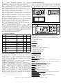
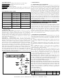
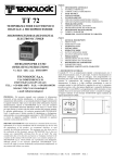
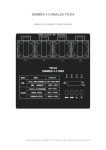
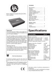
TDV 03
VISUALIZZATORE ELETTRONICO
DIGITALE A MICROPROCESSORE
MICROPROCESSOR-BASED DIGITAL
ELECTRONIC PANEL METER
ISTRUZIONI PER L'USO
OPERATING INSTRUCTIONS
INDICE
1
1.1
1.2
2
3
4
4.1
4.2
5
5.1
6
DESCRIZIONE GENERALE
PANNELLO FRONTALE
CODIFICA DELLO STRUMENTO
DATI TECNICI
INSTALLAZIONE
PROGRAMMAZIONE
PROGRAMMAZIONE DEI PARAMETRI
IMPOSTAZIONE DEI LIMITI DI INGRESSO
DESCRIZIONE DEI PARAMETRI
TABELLA PARAMETRI
PROBLEMI , MANUTENZIONE E GARANZIA
INDEX
1
1.1
1.2
2
3
4
4.1
4.2
5
5.1
6
GENERAL DESCRIPTION
FRONT PANEL
INSTRUMENT CODE
TECHNICAL DATA
INSTALLATION
PROGRAMMING
PROGRAMMING OF PARAMETERS
PROGRAMMING OF INPUT LIMITS
DESCRIPTION OF PARAMETERS
PARAMETERS TABLE
TROUBLES, MAINTENANCE, GUARANTEE
1 - DESCRIZIONE GENERALE
Il modello TDV 03 è un visualizzatore digitale a microprocessore a 3 cifre
programmabile. Lo strumento prevede un ingresso per sonde di temperatura
del tipo PTC (KTY 81), o RTD (Pt100 o Ni100), o Termocoppie (J, K, S)
o per sonde di qualsiasi tipo aventi uscita normalizzata in corrente o in
tensione 4..20 mA, 0..20 mA o 0..10 V.
Vr. 01 (I - GB) - cod.: ISTR 00260
*** GESINT S.r.l. ***
Via Perosi, 5
20010 Bareggio (MI) - ITALY
Tel. +39-02-9014633 / +39-335-6282615
Fax +39-02-90362295
WWW.GESINTSRL.IT
E-mail: [email protected]
PREMESSA: Nel presente manuale sono contenute le informazioni
necessarie ad una corretta installazione e le istruzioni per l'utilizzo e la 1.1 - PANNELLO FRONTALE
manutenzione del prodotto, si raccomanda pertanto di leggere attentamente
le seguenti istruzioni. Ogni cura è stata posta nella realizzazione di questa
documentazione, tuttavia la TECNOLOGIC S.p.A. non può assumersi
alcuna responsabilità derivante dall'utilizzo della stessa. Lo stesso dicasi
per ogni persona o società coinvolta nella creazione del presente manuale.
La presente pubblicazione è di esclusiva proprietà della TECNOLOGIC
S.p.A. la quale pone il divieto assoluto di riproduzione e divulgazione,
anche parziale, se non espressamente autorizzata. La TECNOLOGIC S.p.A.
si riserva di apportare modifiche estetiche e funzionali in qualsiasi
momento e senza alcun preavviso.
1 - Tasto P : Utilizzato per la programmazione dei parametri di
PREVIOUS STATEMENT: In this manual are contained all the necessary funzionamento
information for a correct installation and the instructions for the use and 2 - Tasto DOWN : Utilizzato per il decremento dei valori da impostare o
the maintenance of the product; we recommend, therefore, to read per la selezione dei parametri
carefully the following instructions. The maximum care has been used in 3 - Tasto UP : Utilizzato per l'incremento dei valori da impostare o per la
the realisation of this document, anyway TECNOLOGIC S.p.A. does not selezione dei parametri
assume any responsibility deriving from the use of itself. The same 4 - Led SET : Indica l'ingresso in programmazione parametri
consideration has to be done for each person or Company involved in the (lampeggiante).
creation of this manual. The herewith issue is an exclusive property of
TECNOLOGIC S.p.A. which forbids any reproduction and divulgation, 1.2 - CODIFICA DELLO STRUMENTO
although partial, if not expressly authorised. TECNOLOGIC S.p.A. TDV 03 a b cc
reserves the right to execute aesthetically and functional modifications, at a = ALIMENTAZIONE
any moment and without any notice.
F : 12 VAC/VDC
G : 24 VAC/VDC
TECNOLOGIC - TDV 03 USER MANUAL (I - GB) - Vr. 01 - ISTR 00260 - PAG. 1
b = INGRESSO
C : Termocoppie (J, K, S)
D : Termoresistenze (Pt100, Ni100 IEC)
E : Termistori PTC (KTY 81-121)
F : Segnali normalizzati 4..20 mA
A : Segnali normalizzati 0..20 mA
V : Segnali normalizzati 0..10 V
cc = CODICI SPECIALI
2 - DATI TECNICI
CARATTERISTICHE ELETTRICHE
Alimentazione: 12, 24 VAC/VDC +/- 10%
Frequenza AC: 50/60 Hz
Assorbimento: 2 VA circa
Ingresso/i: 1 ingresso. Per sonde di temperatura tc J, K, S o RTD Pt 100
IEC, Ni 100 o PTC (KTY 81-121 990 Ω a 25 °C) o per segnali
normalizzati 4..20 mA, 0..20 mA o 0..10 V
Classe di protezione contro le scosse elettriche: Classe III
Isolamenti: Nessun isolamento tra alimentazione e ingresso
CARATTERISTICHE MECCANICHE
Contenitore: Plastico autoestinguente UL 94 V0
Dimensioni: 33 x 75 mm, prof. 64 mm
Peso: 90 g circa
Installazione: Incasso a pannello in foro 29 x 71 mm
Connessioni: Morsetti a vite 2,5 mm2
Grado di protezione frontale: IP 65 con guarnizione
Situazione di polluzione: Normale
Temperatura ambiente di funzionamento: 0 ... 55 °C
Umidità ambiente di funzionamento: 30 ... 95 RH% senza condensazione
Temperatura di trasporto e immagazzinaggio: -10 ... +60 °C
CARATTERISTICHE FUNZIONALI
Range di misura: Secondo la sonda utilizzata (vedi tabella)
Risoluzione visualizzazione: Secondo la sonda utilizzata. 1/0,1/5/0,5
Precisione totale: +/- 0,5 % fs
Velocità di acquisizione: 1 acquisizione al secondo
Conformita':Direttiva CEE EMC 89/336 (EN 50081-1, EN 50082-1),
Direttiva CEE BT 73/23 e 93/68 (Apparecchio funzionante ad una tensione
nominale inferiore a 50 VAC e 75 VDC)
TABELLA RANGE DI MISURA
PROBE
3 DIGIT
-50 ... +150 °C
PTC
-58 ... +302 °F
-99 ... +600 °C
Pt 100 (Pt)
-99 ... +999 °F
-50 ... +150 °C
Ni 100 (ni)
-58 ... +302 °F
0 ... +800 °C
tc J (FE)
+32 ... 999 °F
0 ... +999 °C
tc K (Cr)
+32 ... +999 °F
0 ... +999 °C
tc S (rh)
+32 ... +999 °F
- 99 ... 999
4..20 mA, 0..20 mA,
0..10 V (gener.)
3 DIGIT with D.P.
-9.9 ... +99.9 °C
-9.9 ... +99.9 °F
-9.9 ... +99.9 °C
-9.9 ... +99.9 °F
-9.9 ... +99.9 °C
-9.9 ... +99.9 °F
-------9.9 ... 99.9
sovracorrenti, si raccomanda pertanto di proteggere adeguatamente tutti i
circuiti connessi allo strumento con dispositivi (es. fusibili) adeguati alle
correnti circolanti. Si raccomanda di utilizzare cavi con isolamento
appropriato alle tensioni e alle temperature di esercizio e di fare in modo
che i cavi degli ingressi siano tenuti distanti dai cavi di alimentazione e da
altri cavi di potenza. Se il cavo degli ingressi è schermato è preferibile
collegarlo a terra da un solo lato. Per l'alimentazione dell'apparecchio si
raccomanda l'uso dell'apposito trasformatore TCTR, o di trasformatore con
caratteristiche equivalenti, e di utilizzare un trasformatore per ogni
apparecchio.
4 - PROGRAMMAZIONE
4.1 - PROGRAMMAZIONE DEI PARAMETRI
Per avere accesso ai parametri di funzionamento dello strumento occorre
premere il tasto P e mantenerlo premuto per circa 5 secondi, trascorsi i
quali il led SET lampeggierà e il display visualizzerà il codice che
identifica il primo parametro. A questo punto è possibile rilasciare il tasto P
e agendo sui tasti UP o DOWN selezionare il parametro desiderato. Una
volta selezionato il parametro sul quale si intende operare premere il tasto
P e mantenerlo premuto, verrà quindi visualizzato il valore impostato. Per
modificare tale valore mantenere sempre premuto il tasto P e agire
contemporaneamente sui tasti UP o DOWN. Una volta impostato il valore
desiderato rilasciare il tasto P e il display mostrerà nuovamente la sigla del
parametro selezionato. Agendo sui tasti UP o DOWN è quindi possibile
selezionarne un altro e modificarlo come descritto. Per uscire dal modo di
programmazione non agire su alcun tasto per circa 20 secondi, lo strumento
si riporterà automaticamente al modo di funzionamento normale
visualizzando il valore di processo.
Attendere sempre l'uscita dalla fase di programmazione poichè se lo
strumento viene spento prima dell'uscita tutti i dati inseriti durante l'ultima
sessione non saranno memorizzati.
4.2 - IMPOSTAZIONE DEI LIMITI DI INGRESSO
Se lo strumento è predisposto con ingresso per segnali normalizzati 4..20
mA, 0..20 mA o 0..10 V è necessario impostare i limiti di ingresso per la
corretta visualizzazione della misura. Ad esempio se la sonda da collegare
ha un range 0..100 bar sarà necessario impostare 0 come al parametro
"Lci" ( riferimento minimo o inizio scala) e 100 al parametro "Hci"
(riferimento massimo o fine scala). Analogamente se si decide di avere una
visualizzazione con punto decimale occorrerà modificare detti parametri.
Ad esempio se lo strumento è collegato ad una sonda di umidità con un
range 20..99 %RH e si decide di visualizzare la grandezza con il punto
decimale occorrerà prima impostare il par. "dP" come "on" e
successivamente i parametri "Lci" a 20.0 e "Hci" a 99.9.
3 - INSTALLAZIONE
MONTAGGIO MECCANICO: Lo strumento, in contenitore 33 x 75 mm,
è concepito per il montaggio ad incasso a pannello. Praticare quindi un foro
29 x 71 mm ed inserirvi lo strumento fissandolo con l'apposita staffa
fornita. Si raccomanda di montare l'apposita guarnizione per ottenere il
grado di protezione frontale IP 65. Evitare di collocare la parte interna
dello strumento in luoghi soggetti ad alta umidità o sporcizia. Installare lo
strumento il più lontano possibile da fonti che possono generare disturbi
elettromagnetici e quindi anche da motori, teleruttori, relè, elettrovalvole
ecc.
COLLEGAMENTI ELETTRICI: Effettuare le connessioni collegando
un solo conduttore per morsetto e seguendo lo schema riportato,
5 - DESCRIZIONE DEI PARAMETRI
controllando che la tensione di alimentazione sia quella indicata sullo
Di seguito vengono descritti tutti i parametri di cui lo strumento può essere
strumento. Lo strumento, essendo previsto per collegamento permanente
dotato, si fa presente che alcuni di essi potranno non essere presenti o
entro un'apparecchiatura, non è dotato di dispositivi interni di protezione da
perchè dipendono dal tipo di strumento utilizzato.
TECNOLOGIC - TDV 03 USER MANUAL (I - GB) - Vr. 01 - ISTR 00260 - PAG. 2
Lci
LIMITE
INFERIORE
INGRESSO
PER
SEGNALI
NORMALIZZATI : Valore che lo strumento deve visualizzare quando al
circuito di ingresso è presente il valore minimo (4 mA, 0 mA, 0 V).
Hci - LIMITE SUPERIORE INGRESSO PER SEGNALI
NORMALIZZATI:Valore che lo strumento deve visualizzare quando al
circuito di ingresso è presente il valore massimo (20 mA, 10 V).
CAL - CALIBRAZIONE: Offset positivo o negativo che viene sommato al
valore letto dalla sonda prima della visualizzazione. Questo parametro può
rendersi necessario per una ritaratura dello strumento.
PSE - SONDA IN INGRESSO: Permette di selezionare, se il modello dello
strumento è per termocoppie o per termoresistenze, vari eventuali tipi di
sonda in ingresso: per termocoppie J (FE), K (Cr) , S (rh) e per
termoresistenze Pt100 (Pt), Ni100 (ni). Al cambio di questo parametro si
raccomanda di attendere l'uscita dalla fase di progammazione e quindi di
spegnere e riaccendere lo strumento.
dP - PUNTO DECIMALE: Permette di inserire il punto decimale nella
visualizzazione e quindi di stabilire la risoluzione del display (1 o 0,1) (on=
con punto decimale, oF=senza punto decimale). (disponibile solo nei
modelli con ingresso PTC, RTD o per segnali normalizzati)
rou - UNITA' DI MISURA: Stabilisce, per misure di temperatura, la
visualizzazione in gradi Centigradi o Fahrenheit.
hdd
APPROSSIMAZIONE
ULTIMA
CIFRA:
Permette
l'approssimazione della cifra meno significativa. In quest'ultima infatti, se
inserita la funzione, verrà visualizzato 0 se il valore effettivo è compreso tra
0 e 4, oppure 5 se il valore è compreso tra 5 e 9. Ad esempio se la funzione
è inserita e la misura fatta dallo strumento risulta essere 78 il display
visualizzerà 75, oppure se la misura è 70.3 il display visualizzerà 70.0
(n=senza approssimazione, y=con approssimazione).
tAb - PARAMETRO NON MODIFICABILE
5.1 - TABELLA PARAMETRI
Par.
Descrizione
Lci Limite inferiore ingresso
per segnali normalizzati
Hci Limite superiore ingresso
per segnali normalizzati
CAL Calibrazione
PSE
Sonda in ingresso
Def.
-99
-99 ... 999
999
-99 ... +999
0
Note
Tc: FE - Cr - rh Tc: FE
Rtd: Pt - Ni
Rtd: Pt
on - oF
oF
dP
Punto decimale
rou
Unità di misura
hdd
Approssimazione
ultima
cifra
Parametro non modificabile
tAb
Range
-99 ... 999
°C - °F
°C
y-n
n
---
---
6 - PROBLEMI, MANUTENZIONE E GARANZIA
SEGNALAZIONI DI ERRORE: Lo strumento prevede la visualizzazione
dei messaggi di errore sonda "EEE" , in caso la sonda sia interrotta o in
overrange, oppure "- - -" nel caso la sonda (PTC, RTD o per segnali
normalizzati) sia in cortocircuito o in underrange, in tal caso verificare la
corretta connessione della sonda con lo strumento e successivamente
procedere alla verifica della stessa.
PULIZIA: Si raccomanda di evitare l'utilizzo di detergenti abrasivi o
contenenti solventi che possono danneggiare lo strumento.
GARANZIA E RIPARAZIONI: Lo strumento è garantito da vizi di
costruzione o difetti di materiale riscontrati entro i 12 mesi dalla data di
consegna. La garanzia si limita alla riparazione o la sostituzione del
prodotto. L'eventuale apertura del contenitore, la manomissione dello
strumento o l'uso e l'installazione non conforme del prodotto comporta
automaticamente il decadimento della garanzia. In caso di prodotto
difettoso in periodo di garanzia o fuori periodo di garanzia contattare
l'ufficio vendite TECNOLOGIC per ottenere l'autorizzazione alla
spedizione. Il prodotto difettoso, quindi , accompagnato dalle indicazioni
del difetto riscontrato, deve pervenire con spedizione in porto franco presso
lo stabilimento TECNOLOGIC salvo accordi diversi.
1 - GENERAL DESCRIPTION
TDV 03 is a programmable digital microprocessor based panel meter with
3 digit. The instrument has 1 input for PTC (KTY 81), or RTD (Pt 100 or
NI100), or Thermocouple (J-K-S) temperature probes or for any kind of
probe having normalised output in current (4..20 mA, 0..20 mA) or voltage
(0..10 V).
1.1 - FRONT PANEL
1 - Key P : Used to program the functioning parameters
2 - Key DOWN : Used to decrease the values or to select parameters
3 - Key UP : Used to increase the values or to select parameters
4 - Led SET : Signalize the parameters programming mode (flashing)
1.2 - INSTRUMENT CODE
TDV 03 a b cc
a = SUPPLY
F : 12 VAC/VDC
G : 24 VAC/VDC
b = INPUT
C : Termocouples (J, K, S)
D : Termoresistances (Pt100, Ni100 IEC)
E : Termistors PTC (KTY 81-121)
F : Normalized signals 4..20 mA
A : Normalized signals 0..20 mA
V : Normalized signals 0..10 V
cc = SPECIAL CODES
2 - TECHNICAL DATA
ELECTRICAL DATA
Supply: 12, 24 VAC/VDC +/- 10%
Frequency AC: 50/60 Hz
Power consumption: 2 VA approx.
Input/s: 1 input. For temperature probes tc J, K, S or RTD Pt 100 IEC, Ni
100 or PTC (KTY 81-121 990 Ω at 25 °C) or for normalized signals 4..20
mA, 0..20 mA o 0..10 V
Protection class against electric shock: Class III
Insulation: No insulation between supply and input
MECHANICAL DATA
Housing: Self-extinguishing plastic, UL 94 V0
Dimensions: 33 x 75 mm, depht 64 mm
Weight: 90 g approx.
Mounting: Flush in panel in 29 x 71 mm hole
Connections: 2,5 mm2 screw terminal block
Degree of protection of front panel : IP 65 mounted in panel with gasket
Pollution situation: Normal
Operating temperature: 0 ... 55 °C
Operating humidity: 30 ... 95 RH% without condesation
Storage temperature: -10 ... +60 °C
TECNOLOGIC - TDV 03 USER MANUAL (I - GB) - Vr. 01 - ISTR 00260 - PAG. 3
FUNCTIONAL DATA
Measurement range: according to the used probe (see table range)
Display resolution: according to the probe used 1/0,1/5/0,5
Overall accuracy: +/- 0,5 % fs
Sampling rate: 1 sample per second
Compliance: ECC directive EMC 89/336 (EN 50081-1, EN 50082-1), ECC
directive LV 73/23 and 93/68 (Instrument oparating under 50 VAC and 75
VDC)
MEASUREMENT RANGE TABLE
PROBE
3 DIGIT
-50 ... +150 °C
PTC
-58 ... +302 °F
-99 ... +600 °C
Pt 100 (Pt)
-99 ... +999 °F
-50 ... +150 °C
Ni 100 (ni)
-58 ... +302 °F
0 ... +800 °C
tc J (FE)
+32 ... 999 °F
0 ... +999 °C
tc K (Cr)
+32 ... +999 °F
0 ... +999 °C
tc S (rh)
+32 ... +999 °F
- 99 ... 999
4..20 mA, 0..20 mA,
0..10 V (gener.)
3 DIGIT with D.P.
-9.9 ... +99.9 °C
-9.9 ... +99.9 °F
-9.9 ... +99.9 °C
-9.9 ... +99.9 °F
-9.9 ... +99.9 °C
-9.9 ... +99.9 °F
---
4 - PROGRAMMING
4.1 - PROGRAMMING OF PARAMETERS
To accede to the operating parameters it is necessary to press key P
holding it down for about 5 seconds, afterwhich the led SET will flash and
the code of the first parameter will be visualized on the display. At this
point key P can be released and by pressing UP or DOWN the desired
parameter can be selected. Once the parameter on which we intended to
operate has been selected to modify it press P, while holding it down, the
set of the parameter will show up. To modify this value keep P pressed
while acting on UP or on DOWN so as to increase or decrease the value.
Once the desired value has been set release P and the selected parameter
code can be read on the display. By pressing UP or DOWN it is therefore
possible to choose another one and modify it as previously mentioned. To
outgoing from the programming mode no key is to be pressed for about 20
seconds, the instrument will automatically return to normal functioning
mode, visualizing the process value.
The instrument must not to be switched off during the programming mode
otherwise the data inserted in the last session will not be memorized.
---
4.2 - PROGRAMMING OF INPUT LIMITS
If the instrument is provided with input for normalized signals 4..20 mA,
--0..20 mA or 0..10 V it is necessary to set input limits to have the correct
measure indication. For example: if the probe to connect has a range of
-9.9 ... 99.9
0..100 bar, it will be necessary to program 0 on "Lci" parameter (start
scale) and 100 on "Hci" parameter (end scale). At same time, we have to
modify the same parameters to have the decimal point. Example:
3 - INSTALLATION
instrument connected with relative humidity probe with 20..99 %RH as
MECHANICAL MOUNTING: The instrument, in case 33 x 75 mm, is
range, to have the decimal point it will occour to program "dP" in "on"
designed for panel mounting. Make an hole 29 x 71 mm and insert the
mode, "Lci" at 20.0 and "Hci" at 99.9.
instrument, fixing it with the provided special bracket . We recommend to
mount the gasket to obtain an IP 65 front protection. Avoid to place the
5 - DESCRIPTION OF PARAMETERS
instrument in areas with humidity or dirt. Connect the instrument as far as
Here following are described all the instrument parameters; pls. note that
possible from source of electromagnetic disturbances so as motors, power
some of them could do not appear or because are according to the kind of
relays, relays, electrovalves,etc.
used instrument or because are automatically not qualified, as they're not
ELECTRICAL
CONNECTIONS: Carry out the electrical wiring
necessary.
connecting only one wire for each terminal , according to the following
Lci - LOWER NORMALIZED SIGNALS INPUT LIMIT: Value that the
diagram, check that the power supply is the same as indicated on the
instrument must to indicate in correspondance of minumum value (4 mA, 0
instrument. The instrument, being a built in equipment with permanent
mA, 0 V).
connection into a cabinet, is not furnished with internal device protecting
Hci - HIGHER NORMALIZED SIGNALS INPUT LIMIT: Value that the
from overcurrent : it's recommended , therefore, to properly protect all the
instrument must to indicate in correspondance of maximum value (20 mA,
electric circuits connected to the instrument, with devices (ex. fuses)
10 V).
proportionate to the circulating currents. It's strongly recommended to use
CAL - CALIBRATION: Positive or negative offset which is calculated on
cables with proper insulation, according to the working voltages and
probe reading before visualizing. This parameter can be utilized when a
temperatures. Furthermore, the input cables has to be kept separate from
recalibration of the instrument is desired.
line voltage wiring. If the input cables is screened, it has to be connected
on the ground with only one side. It's recommended to supply the PSE - INPUT PROBE: Allows selecting, if the instrument type is for
instrument using the Tecnologic TCTR transformer or equivalent type, and thermocouples or for thermoresistances, various types of probe: J (FE), K
(Cr), S (rh) for thermocouples and Pt100 (Pt), Ni100 (ni) for
to use one transformer for each instrument.
thermoresistances. On changing this parameter it is to be remember that
the exit programming phase is to be carried out first afterwhich the
instrument is to be switched off and then on again.
dP - DECIMAL POINT : Allows the insertion of the decimal point on the
display and therefore to determine resolution of the reading value (1 or
0,1) (on= with decimal point, oF=without decimal point).(available only
for models provided for PTC, RTD and normalized signals input).
rou - UNIT OF MEASUREMENT: Determines the visualization of the
temperature in Centigrade or Fahrenheit degree.
hdd - HALF DIGIT DISPLAY: This parameter allows the approximation of
the last digit at right side. Infact when this parameter is in on mode, on this
digit will be show 0 when the real measuring value is between 0 and 4, and
will be show 5 when the real measuring value is between 5 and 9. For
example if the real measure is 78 display will show 75, or if the real
measure is 70.3 the display will show 70.0 (n=without approximation,
y=with approximation).
tAb - FIXED PARAMETER
6.1 - PARAMETERS TABLE
Par.
Description
Lci Lower limit for normalized
signal input
TECNOLOGIC - TDV 03 USER MANUAL (I - GB) - Vr. 01 - ISTR 00260 - PAG. 4
Range
-99 ... 999
Def.
-99
Notes
Hci
Higher limit for normalized
signal input
CAL Calibration
PSE
Input probe
dP
Decimal point
rou
Unit of measurement
hdd
tAb
-99 ... 999
999
-99 ... +999
0
Tc: FE - Cr - rh Tc: FE
Rtd: Pt - Ni Rtd: Pt
on - oF
oF
°C - °F
°C
Half digit display
y-n
n
Fixed parameter
---
---
7 - PROBLEMS, MAINTENANCE AND WARRANTY
ERRORS SIGNALLING: The instrument shows the error message
"EEE" , when the probe is interrupted or in overrange, or "- - -" when
the probe (PTC, RTD or normalised signals) is in short-circuit or
underrange; in this case verify the correct probe wiring with the
instrument and afterward proceed to verify itself.
HOW TO CLEAN: We recommend to avoid abrasive cleaners or
containing solvents which could damage the instrument.
WARRANTY AND REPAIRS: The instrument is under warranty against
construction vices or defected material, noticed within 12 months from
delivery date.The warranty is limited to the repairs or to the substitution of
the instrument. The eventual opening of the housing, the violation of the
instrument or the wrong use and installation of the product means the
automatically decay of the warranty. In case of defected instrument,
noticed in warranty period or out of warranty, do contact our sales
department to obtain the shipment authorisation. The defected product
must be shipped to TECNOLOGIC with the detailed description of the
failures found and without any fees or charge for Tecnologic, safe
different agreements.
TECNOLOGIC - TDV 03 USER MANUAL (I - GB) - Vr. 01 - ISTR 00260 - PAG. 5