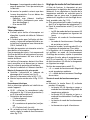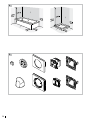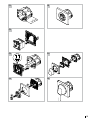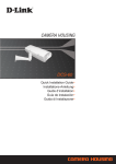
1
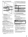
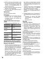
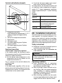
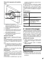
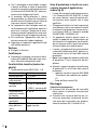
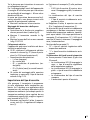
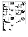
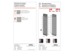
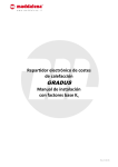
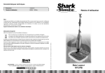
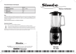
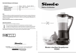
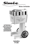
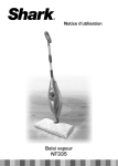
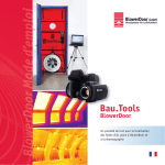
4
2
3
1
5
2013/08 • 6912014
DE –
EN –
IT –
FR –
Gebrauchs- und Montageanleitung Thermostat WKS für Elektro-Heizstab
Instructions for use and installation instructions, WKS thermostat for electrical heating
element
Istruzioni d'uso e di montaggio termostato WKS per barra termica elettrica
Instructions d'utilisation et de montage Thermostat WKS d'ambiance pour l'élément chauffant électrique
AKP®
Arbonia AG
Amriswilerstrasse 50
CH-9320 Arbon
T +41 71 447 47 47
F +41 71 447 48 47
www.arbonia.ch
AKP®
AFG Arbonia-Forster-Riesa
GmbH
Heinrich-Schönberg-Str. 3
DE-01591 Riesa
T +49 3525 74 60
F +49 3525 74 62 57
www.arbonia.de
AKP®
Arbonia Kermi France Sárl
17A rue d’Altkirch
CS 70053
FR-68210 Hagenbach
T +33 389 40 02 53
C +33 389 40 04 25
www.arbonia.fr
AKP®
Ufficio Arbonia AG /
Kermi GmbH
Strada degli Angariari, 8
RSM-47891 Falciano
T +378 549 941 372
F +378 549 974 931
www.arbonia.it
DE – Gebrauchsanleitung
Zulässiger Gebrauch
Der Thermostat dient zur Regulierung der
Raumtemperatur oder der Temperatur des
Heizkörpers, z. B. zum Wärmen von Handtüchern, in Verbindung mit einem Elektro-Heizstab in ortsfesten Heizkörpern.
Jeder andere Gebrauch ist nicht bestimmungsgemäß und daher unzulässig.
Sicherheitshinweise
►► Das Gerät nicht vor der endgültigen und
ordnungsgemäßen Installation benutzen.
WARNUNG
Verbrennungsgefahr! Einige Teile
des Heizkörpers können sehr
heiß werden.
►► Beaufsichtigen Sie Kinder, damit diese nicht mit dem Gerät
spielen.
►► Beachten Sie mitgeltende Anleitungen des Heizstabs und
des Heizkörpers.
Das Gerät kann von Personen mit
beschränkten körperlichen, sensorischen und geistigen Fähigkeiten
oder mangelnder Erfahrung und
Wissen sowie Kindern ab 8 Jahren und darüber benutzt werden,
wenn sie beaufsichtigt oder bezüglich des sicheren Gebrauchs des Gerätes unterwiesen wurden und die
daraus resultierenden Gefahren
verstehen.
Kinder jünger als 3 Jahre sind vom
Gerät fernzuhalten, es sei denn, sie
werden ständig überwacht.
2
Kinder ab 3 Jahren und jünger als
8 Jahre dürfen das Gerät unter
obigen Voraussetzungen nur einund ausschalten, sofern das Gerät
in seiner normalen Gebrauchslage
platziert oder installiert ist.
Kinder ab 3 Jahren und jünger als
8 Jahre dürfen das Gerät nicht reinigen und nicht die Wartung durch
den Benutzer durchführen.
Reinigung
►► Trennen Sie das Gerät vor der Reinigung
oder Wartung von der Stromversorgung.
►► Verwenden Sie nur milde, nicht scheuernde
Reinigungsmittel.
Reklamation
►► Wenden Sie sich an Ihren Fachhandwerker.
Montage und Reparaturen
►► Lassen Sie die Montage und Reparaturen
nur vom Fachhandwerker ausführen, damit
Ihre Gewährleistungsansprüche nicht erlöschen.
Entsorgung
►► Führen Sie das Gerät der ge-
trennten Sammlung von Elektround Elektronikgeräten zu. Beachten Sie die örtlichen Vorschriften.
Bedien- und Anzeigeelemente
Aus Sicherheitsgründen schaltet der Thermostat bei Erreichen einer Raumtemperatur von
ca. 28 °C (Betriebsart Raumtemperaturregelung) bzw. ca. 35 °C (Betriebsart Handtuchwärmen) ab.
Anzeigen
2
1
4
LED-Anzeige
Betriebsmodus (4)
Bedeutung
5
Leuchtet rot
Heizphase
6
3
Leuchtet gelb Solltemperatur ist erreicht,
Heizstab ist abgeschaltet
Blinkt rot
Boost-Modus ist aktiv
DE – Montageanleitung
1 Temperaturregler
Raumtemperatur ca. 7–27 °C
Heizkörpertemperatur ca. 40–65 °C
2 Skala des Temperaturreglers
3 Boost-Taste
4 LED-Anzeige Betriebsmodus
5 LED-Anzeige Betriebzustand fil pilote
(länderspezifisch)
6 LED-Anzeige Betriebzustand fil pilote
(länderspezifisch)
Funktionen / Bedienung
Komfort-Modus – Temperaturregelung
Im Komfort-Modus hält der Thermostat das
Temperaturniveau durch Ein- und Ausschalten
des Heizstabs konstant.
►► Stellen Sie am Temperaturregler (1) die
gewünschte Raumtemperatur bzw. das gewünschte Temperaturniveau des Heizkörpers ein.
Die Position "❄" auf der Skala (2) kennzeichnet die Frostschutz-Einstellung.
Boost-Modus
Im Boost-Modus heizt der Heizstab unabhängig vom eingestellten Temperaturniveau
durchgehend für 60 Minuten. Danach schaltet
der Thermostat in den Komfort-Modus zurück.
►► Um den Boost-Modus zu aktivieren oder
vorzeitig abzubrechen, drücken Sie kurz
die Taste (3).
Das Gerät darf nur von einer Elektrofachkraft
(in Deutschland gemäß BGV A3) angeschlossen
werden.
Sicherheitshinweise
►► Vor der Montage und Inbetriebnahme die-
se Anleitung gründlich lesen.
►► Nach der Montage die Anleitung dem End-
verbraucher überlassen.
WARNUNG
Lebensgefahr durch Stromschlag!
►► Gerät nur im spannungsfreien Zustand
montieren und anschließen.
Einsatzbedingungen
►► Thermostat nur in Verbindung mit Elektro-
Heizstäben aus dem Lieferprogramm des
Herstellers montieren.
►► Bei Montage in Räumen mit Bade- bzw.
Duscheinrichtungen: Schutzbereiche gemäß nationalen Installationsnormen (in
Deutschland DIN VDE 0100-701) beachten.
Darüber hinaus alle örtlichen Vorschriften
beachten.
►► Bei der Installation eine bauseitige Fehlerstromschutzeinrichtung vorsehen (Auslösegrenze kleiner gleich 30 mA).
3
►► Wird ein Gerät ohne Stecker direkt an die
fest verlegte elektrische Installation angeschlossen: Trennvorrichtung gemäß den
örtlichen Einrichtungsbestimmungen zur
Netztrennung einbauen.
►► Gerät nur mit der zugelassenen Spannung
betreiben (siehe Typenschild).
►► Gerät nur in der Schutzverpackung lagern
und transportieren.
Reklamation
►► An den Lieferanten wenden.
Entsorgung
►► Verpackung und nicht benötigte Teile dem
Recycling oder der ordnungsgemäßen
Entsorgung zuführen. Die örtlichen Vorschriften beachten.
Technische Merkmale (siehe Typenschild)
• Entspricht der Norm EN 60 730-1, -2-9
Nennspannung
Leitungsquerschnitt
Maximale Schaltleistung
Belastbarkeit des
Kontakts
230 V AC
2 x 1,5 mm²
1800 W
8 A / 250 V ~ bei cos φ = 1
bzw.
2 A / 250 V ~ bei cos φ = 0,6
Leistungsaufnahme ca. 0,6 W
im Stand-by-Modus
Isolationsart
Schutzklasse II
Thermostat
Schutzart
IPX4 nach sachgemäßer
Wandauslass
Montage
Schutzbereiche in Räumen mit Badebzw. Duscheinrichtung (Ausführungsbeispiele siehe Abb. A)
• Gemäß nationalen Installationsnormen (in
Deutschland DIN VDE 0100-701) dürfen in
Räumen mit Badewanne oder Dusche elektrische Betriebsmittel nur in bestimmten
Bereichen montiert werden.
• Elektrische Geräte in oben genannten
Räumen sind zulässig, wenn diese durch
eine Fehlerstromschutzeinrichtung (RCD)
(in Deutschland gemäß DIN EN 61008-1
(VDE 0664-10)) geschützt sind.
• Elektrische Geräte sind so zu installieren,
4
dass Schalter und andere Regel- und / oder
Steuereinrichtungen nicht von einer Person
in der Wanne oder der Dusche berührt werden können.
• Steckdosen sowie Schalt- und Steuergeräte
(Thermostat WKS) dürfen nur außerhalb
der Schutzbereiche montiert werden.
• Hinweis: Die Montage der Produkte im
Schutzbereich 1 ist vom Hersteller nicht zugelassen.
►► Folgende Produkte nur im Schutzbereich 2
oder außerhalb der Schutzbereiche montieren:
–– Heizkörper mit Heizstab (DIN 55900
"Beschichtungen für Raumheizkörper"
beachten)
–– Wandauslass IPX4
Montage
Vorbereitende Tätigkeiten
►► Sicherstellen, dass in Kabelreichweite des
Heizstabs eine Schalterdose vorhanden ist.
►► Sicherstellen, dass an der für den Ther-
mostateinsatz vorgesehenen Stelle eine
weitere Schalterdose mit Spannungsversorgung (230 V, Absicherung B16 A) vorhanden ist.
Zwischen beiden Schalterdosen wird eine Leitungsverbindung benötigt.
Für den Einbau der Geräteeinsätze empfiehlt
es sich, Schalterdosen mit einer Einbautiefe
≥40 mm und einem Durchmesser von 68 mm
zu verwenden.
Die Schalterdosen müssen frei zugänglich sein
und dürfen nicht in der Projektionsfläche des
Heizkörpers liegen.
►► Heizkörper und Heizstab montieren.
Thermostat und Wandauslass montieren
►► Lieferumfang auf Vollständigkeit und Schäden prüfen (siehe Abb. B).
►► Thermostat gemäß Abb. C1-C5 montieren.
►► Wandauslass gemäß Abb. C1 / D1-D2 montieren.
Elektrischer Anschluss
Das Gerät darf nur von einer Elektrofachkraft
angeschlossen werden.
►► C3 / D1: Elektrischen Anschluss gemäß Schema Abb. E1 (Schutzklasse I) bzw. E2 (Schutzklasse II) herstellen.
• Benennung der Adern:
––
––
––
––
L = Phase (braun)
N = Neutral (blau)
PE = Schutzleiter (grün / gelb)
FP = fil pilote (schwarz) (bauseits)
►► C4: Vor Montage der Abdeckungen bei Bedarf die Betriebsart gemäß Abb. F1-F3 einstellen.
Einstellung der Betriebsart
Der Thermostat ist im Auslieferungszustand
auf die Regulierung der Raumtemperatur
programmiert. Wird eine raumtemperaturunabhängige Regulierung der Temperatur des
Heizkörpers gewünscht (z. B. weil die Raumtemperatur über eine Flächenheizung geregelt wird), folgende Schritte gemäß Abb. F1-F3
ausführen:
►► Rahmen sowie Skalenblende (2) und Temperaturregler (1) vorsichtig abnehmen.
►► Drehschalter (7) auf Position "1" stellen.
–– Betriebsarten-LED (4) zeigt durch gelbes
Blinken die Umstellung an.
Die Anzeige der Betriebsart erlischt.
–– Betriebsart Handtuchwärmen ist aktiv.
►► Rahmen, Skalenblende (2) und Temperaturregler (1) wieder aufsetzen.
Wird anstelle der Betriebsart Handtuchwärmen wieder die Regulierung der Raumtemperatur gewünscht, die oben genannten Schritte
wiederholen. Dazu den Drehschalter (7) auf
Position "0" stellen. Die Betriebsarten-LED (4)
zeigt durch rotes Blinken die Umstellung an.
Position des Drehschalters (7):
• "0" = Betriebsart Raumtemperaturregelung
• "1" = Betriebsart Handtuchwärmen
Anzeige der eingestellten Betriebsart
►► Boost-Taste (3) ca. 10 Sekunden lang ge-
drückt halten.
–– LED-Anzeige (4) blinkt rot –> Betriebsart
Raumtemperaturregelung
–– LED-Anzeige (4) blinkt gelb –> Betriebsart
Handtuchwärmen
–– Die Anzeige der Betriebsart erlischt.
–– Der Thermostat ist betriebsbereit.
5
EN – Instructions for use
Permissible use
The thermostat is used for regulating the room
temperature or the temperature of the radiator, for e.g. for warming towels, in conjunction
with an electrical heating element in stationary radiators.
Any other use is contrary to its intended purpose and therefore not permissible.
►► Disconnect the device from the power sup-
Safety instructions
Complaint
►► Do not use the device before complete and
proper installation.
WARNUNG
Risk of burns! Some parts of the
radiator may be very hot.
►► Supervise children so that they
do not play with the device.
►► Observe the applicable instruction manuals of the heating element and the radiator.
The device may be used by persons
with limited physical, sensory and
mental abilities or by persons with
little experience and knowledge
as well as children above 8 years
under supervision or they are instructed regarding the safe use of
the device and understand the risk
resulting therefrom.
Children less than 3 years are to be
kept away from the device unless
they are monitored continuously.
Children above 3 years and less than
8 years may only switch on and off
the device under above mentioned
conditions, provided the device is
placed and installed in its normal
position.
6
Children above 3 years and less
than 8 years may not clean the
device and may also not carry out
maintenance by the user.
Cleaning
ply before cleaning or maintenance.
►► Use only mild, non-abrasive cleansing
agents.
►► Contact your local dealer.
Installation and repairs
►► Have the installation and repairs performed
by a specialized tradesman so that your
claims under warranty are not forfeited.
Disposal
►► Dispose of the unit in the sepa-
rate collection for electrical and
electronic devices. Observe local
regulations.
Control and indicator elements
2
1
►► To activate the boost mode or early cancel-
lation, press the button (3) briefly.
For safety reasons, the thermostat switches off
on reaching a room temperature of approximately 28 °C (room temperature regulation
mode) or approximately 35 °C (towel warming
mode).
4
5
6
3
Display
LED display
mode (4)
Meaning
Lights red
Heating phase
Lights yellow Setpoint temperature has
been reached, heating element is switched off
Blinks red
1 Temperature controller
room temperature approximately 7–27 °C
radiator temperature approximately
40–65 °C
2 Scale of the temperature controller
3 Boost button
4 LED display mode
5 LED display operating state fil pilote
(country-specific)
6 LED display operating state fil pilote
(country-specific)
Functions / operation
Comfort mode - temperature regulation
In the comfort mode, the thermostat retains
the temperature level by switching the heating
element on and off constantly.
►► Set the desired room temperature or the
temperature level of the radiator on the
temperature controller (1).
The "❄" position on the scale (2) indicates the
antifreeze setup.
Boost mode
In the boost mode, regardless of the set temperature level, the heating element heats continuously for 60 minutes. The thermostat then
switches back to the comfort mode.
Boost mode is active
EN – Installation instructions
The device may only be connected by an electrical specialist. An electrical specialist is someone whose technical training, knowledge,
experience and knowledge of the relevant
regulations allows him to assess the tasks assigned to him and recognise potential hazards.
Safety instructions
►► Read these instructions thoroughly prior to
installation and commissioning.
►► After installation pass the instructions on
to the end used.
WARNING
Danger of death from electric shocks!
►► Install and connect the device only in the
de-energized state.
Operating conditions
►► Install thermostat only in conjunction
with electrical heating elements from the
manufacturer's product range.
►► When installing in rooms with bath or shower facilities: take into account protective
areas according to national installation
standards (in Germany DIN VDE 0100-701).
Also follow all local regulations.
►► When installing , provide an on-site residual-current-operated protective device (with
trigger limit less than or equal to 30 mA).
7
►► If a device without a connector is directly
connected to the fixed electrical installations: install an isolator in accordance with
the local provisions for mains disconnection.
►► Operate the device only with the approved
voltage (see type plate).
►► Store and transport the device only in the
protective packaging.
Complaint
►► Contact the supplier.
Disposal
►► Packaging and any parts that are not nee-
ded should be recycled or disposed of properly. Observe local regulations.
Technical features (see type plate)
• Corresponds to the standard EN 60 730-1,
-2-9
Nominal voltage
Cable cross section
Maximum switching
capacity
Resilience of the
contact
230 V AC
2 x 1.5 mm²
1800 W
8 A / 250 V ~ at cos φ = 1
or
2 A / 250 V ~ at cos φ = 0,6
approximately 0.6 W
Power consumption in the stand-by
mode
Insulation type
Protection class II
Thermostat
Protection type
IPX4 after proper
wall outlet
installation
Protective areas in rooms with bath
or shower facilities (for installation
examples, see Fig. A)
• According to national installation stan-
dards (in Germany DIN VDE 0100-701) electrical equipment may only be installed in
specific areas in rooms with bathtubs or
shower facilities.
• Electrical equipment is permitted in the
rooms referred to above if it is protected by
a residual current protective device (RCD)
(in Germany according to DIN EN 61008-1
(VDE 0664-10)).
• Electric devices are to be installed such that
the switches and other control and/or regu8
lation equipment cannot be touched by a
person in the bathtub or the shower.
• Sockets, switches and control units (thermostat WKS) may only be installed outside
the protective areas.
• Note: the manufacturer does not approve
the installation of products in protective
area 1.
►► Install the following products only in pro-
tective area 2 or outside the protective areas:
–– radiator with heating element (DIN
55900 note "coatings for radiators".)
–– Wall outlet IPX4
Installation
Preparatory activities
►► Ensure that a outlet socket is there within
the reach of the cable of the heating element.
►► Ensure that there is an additional outlet
socket with power supply (230 V, fuse B16
A) at the location provided for inserting the
thermostat.
A line connection is necessary between the
two outlet sockets.
To install device inserts, it is advisable to use
outlet sockets with an installation depth
≥ 40 mm and diameter of 68 mm.
The outlet sockets must be freely accessible
and may not be in the projection surface of
the radiator.
►► Install radiator and heating element.
Install thermostat and wall outlet
►► Check the delivery for completeness and
damages (see Fig. B).
►► Install thermostat according to Fig. C1 / C5 .
►► Install wall outlet according to Fig. C1 / D1D2.
Electrical connection
The device may only be connected by an electrical specialist.
►► C3/D1: setup electrical connection accor-
ding to the diagram Fig. E1 (protection class
I) or E2 (protection class II).
• Designation of the wires:
–– L = phase (brown)
–– N = neutral (blue)
–– PE = protective conductor (green / yellow)
–– FP = fil pilote (black) (on-site)
►► C4: before installing the cover, set the operating mode according to Fig F1-F3 if necessary.
Setup of the operating mode
In the as-delivered condition, the thermostat
is programmed for regulating the room temperature. If a regulation independent of the
room temperature of the radiator temperature is desired (e.g. because the room temperature is regulated via panel heating), execute
the following steps according to Fig. F1-F3:
►► Remove the frame, the dial (2) and the temperature controller (1) carefully.
►► Set the rotary switch (7) to the "1" position.
–– LED (4) mode displays the conversion by
blinking yellow.
Display of the operating mode goes out.
–– Towel warming mode is active.
►► Attach the frame, the dial (2) and the temperature controller (1) again.
If regulation of room temperature is desired
instead of towel warming, repeat the above
mentioned steps. For this, set the rotary switch
(7) to the "0" position. The LED (4) mode displays the conversion by blinking red.
Position of the rotary switch (7):
• "0" = Room temperature regulation mode
• "1" = towel warming mode
Display of the set mode
►► Keep the boost button (3) pressed for ap-
proximately 10 seconds.
–– LED display (4) blinks red –> room temperature regulation mode
–– LED display (4) blinks yellow –> towel warming mode
–– Display of the operating mode goes out.
–– The thermostat is ready to operate.
9
IT – Istruzioni per l'uso
Uso consentito
Il termostato serve per la regolazione della
temperatura ambiente o della temperatura
del radiatore, ad esempio per il riscaldamento
degli asciugamani, in unione ad una barra termina elettrica in radiatori fissi.
Ogni altro uso non è considerato conforme alle
disposizioni ed è quindi non ammesso.
Pulizia
Indicazioni di sicurezza
►► Staccare l'apparecchio dall'alimentazione
►► Non utilizzare l'apparecchio prima dell'in-
stallazione definitiva e conforme alle norme.
ATTENZIONE
Pericolo di ustioni! Alcune parti
del radiatore possono diventare
molto calde.
►► Sorvegliare i bambini affinché
non giochino con l'apparecchio.
►► Osservare le istruzioni vigenti
della barra termica e del radiatore.
Questo apparecchio può essere utilizzato da persone con limitate capacità fisiche, sensoriali o mentali o
con scarsa esperienza o conoscenza
e da bambini dagli 8 anni in su, se
non lasciati soli o se istruiti sull’utilizzo sicuro dell’apparecchio e in
grado di capire i pericoli che possono sorgere.
I bambini di età inferiore ai 3 anni
devono essere mantenuti lontani
dall'apparecchio, a meno che non
vengano costantemente controllati.
I bambini dai 3 agli 8 anni possono
solo accendere e spegnere l'apparecchio nel rispetto delle condizioni
10
sopra indicate e con l'apparecchio
posizionato o installato nelle sua
posizione d'uso normale.
I bambini dai 3 agli 8 anni non possono pulire l'apparecchio e non
possono eseguire la manutenzione
ad apera dell'utente.
di corrente prima della pulizia o della manutenzione.
►► Utilizzare solo detergenti delicati e non
abrasivi.
Reclamo
►► Contattare l'installatore specializzato.
Montaggio e riparazioni
►► Per non perdere la garanzia sul prodotto,
far eseguire il montaggio e le riparazioni
solo da un installatore specializzato.
Smaltimento
►► Portare l'apparecchio presso i
punti di raccolta separata per
apparecchi elettrici ed elettronici.
Osservare le disposizioni locali.
Elementi di comando e di visualizzazione
2
1
4
5
6
3
1 Regolatore di temperatura
temperatura ambiente circa 7–27 °C
temperatura del radiatore circa 40–65 °C
2 Scala del regolatore di temperatura
3 Tasto Boost
4 Visualizzazione LED modalità di esercizio
5 Visualizzazione LED stato di esercizio fil
pilote (specifico del paese)
6 Visualizzazione LED stato di esercizio fil
pilote (specifico del paese)
Funzioni / Comando
Modalità comfort – regolazione della temperatura
Nella modalità comfort il termostato mantiene
costante il livello della temperatura attraverso
l'accensione e lo spegnimento della barra termica.
►► Sul regolatore di temperatura (1), impostare la temperatura ambiente desiderata o il
livello di temperatura desiderato del radiatore.
La posizione "❄" sulla scala (2) indica l'impostazione protezione antigelo.
Modalità boost
In modalità boost, la barra termica riscalda,
indipendentemente dal livello di temperatura
impostato, in modo continuo per 60 minuti.
Successivamente il termostato torna nella modalità comfort.
►► Per attivare la modalità boost o per inter-
romperla anticipatamente, premere brevemente il tasto (3).
Per motivi di sicurezza il termostato si spegne
al raggiungimento di una temperatura ambiente di circa 28 °C (tipo di esercizio regolazione della temperatura ambiente) o circa 35
°C (tipo di esercizio riscaldamento asciugamano).
Visualizzazioni
Visualizzazione LED
modalità di
esercizio (4)
Significato
Illuminato in
rosso
Fase di riscaldamento
Illuminato in
giallo
La temperatura nominale
è stata raggiunta, la barra
termica è spenta
Lampeggia in La modalità boost è attiva
rosso
IT – Istruzioni di montaggio
L'apparecchio può essere installato solo da un
elettricista specializzato. Elettricista qualificato è colui che per formazione, conoscenza ed
esperienza tecnica nonché conoscenza delle
direttive specifiche in materia, è in grado di
valutare i lavori che gli vengono affidati e di
riconoscere i possibili pericoli che ne derivano.
Indicazioni di sicurezza
►► Leggere attentamente le istruzioni prima
di procedere al montaggio e alla messa in
esercizio.
►► Dopo il montaggio cedere le istruzioni
all'utente finale.
ATTENZIONE
Pericolo di morte per scossa elettrica!
►► Montare e collegare l'apparecchio solo in
assenza di tensione.
Condizioni di utilizzo
►► Montare il termostato solo a barre termi-
che elettriche dal volume di fornitura del
produttore.
11
►► Con il montaggio in locali adibiti a bagno
►►
►►
►►
►►
o doccia: osservare le zone di protezione
secondo le norma di installazione nazionali
(in Germania DIN VDE 0100-701). Inoltre osservare tutte le disposizioni locali.
Al momento dell‘installazione il cliente
deve prevedere un dispositivo di protezione dalle correnti di guasto (con un limite di
intervento minore o uguale a 30 mA).
Se l'apparecchio viene collegato senza spina direttamente all'installazione elettrica a
posa fissa: installare il dispositivo di sezionamento secondo le disposizioni locali relative al dispositivo per la separazione di rete.
Far funzionare l'apparecchio solo con la
tensione consentita (vedere targhetta).
Depositare e trasportare l'apparecchio solo
nell'imballo protettivo.
Reclamo
►► Rivolgersi ai fornitori.
Zone di protezione in locali con vasca
o doccia (esempi di applicazione
vedere fig. A)
• In base alle norme di installazione naziona-
•
•
•
Smaltimento
►► Procedere al riciclaggio o al corretto smalti-
mento dell'imballo e delle parti non necessarie. Osservare le disposizioni locali.
Caratteristiche tecniche (vedere targhetta)
• Conforme alla norma EN 60 730-1, -2-9
Tensione nominale
Sezione del cavo
Capacità di controllo massima
Caricabilità del
contatto
230 V AC
2 x 1,5 mm²
1800 W
8 A / 250 V ~ con cos φ = 1
o
2 A / 250 V ~ con cos φ = 0,6
ca. 0,6 W
Assorbimento di
potenza in modalità stand-by
Tipo di isolamento Classe di protezione II
termostato
Tipo di protezione IPX4 secondo un monpresa dell'aria a
taggio corretto
muro
12
•
li (in Germania DIN VDE 0100-701) in locali
con vasca o doccia, i mezzi di esercizio elettrici possono essere montati solo in zone
specifiche.
Gli apparecchi elettrici nei locali sopra citati
sono ammessi, solo se sono protetti tramite
un dispositivo di protezione contro corrente di guasto (RCD) (in Germania secondo
DIN EN 61008-1 (VDE 0664-10)).
Gli apparecchi elettrici devono essere installati in modo tale che l'interruttore e gli
altri dispositivi di regolazione e/o di comando non possano essere toccati da persone
all'interno della vasca o della doccia.
Le prese, gli apparecchi di commutazione
e comando (termostato WKS), possono essere montati solo al di fuori delle zone di
protezione.
Nota: il montaggio del prodotto nella zona
di protezione 1 non è consentito dal produttore.
►► Montare i seguenti prodotti solo nella zona
di protezione 2 o al di fuori delle zone di
protezione:
–– radiatore con barra termica (DIN 55900
"Rivestimenti per radiatori per ambienti")
–– Presa dell'aria a muro IPX4
Montaggio
Operazioni di preparazione
►► Assicurarsi che alla portata del cavo della
barra termica sia presente una presa per
interruttore.
►► Assicurarsi che sul punto previsto per l'inserto per termostato sia presente un'ulteriore presa per interruttore con alimentazione di tensione 230 V, fusibile B16 A).
Tra le due prese per interruttore è necessaria
un collegamento con cavi.
Per il montaggio degli inserti dell'apparecchio
si consiglia di utilizzare prese per interruttore
con profondità di montaggio ≥ 40 mm ed un
diametro di 68 mm.
Le prese per interruttore devono essere facilmente accessibili e non devono trovarsi nelle
superfici di proiezione del radiatore.
►► Montare il radiatore e la barra termica.
Montaggio del termostato e della presa
dell'aria a muro
►► Controllare che la fornitura sia completa e
che non presenti danni (vedere fig. B).
►► Montare il termostato secondo la fig.
C1 / C5 .
►► Montare la presa dell'aria a muro secondo
la fig. C1 / D1-D2.
Collegamento elettrico
L'apparecchio può essere installato solo da un
elettricista specializzato.
►► C3 / D1: realizzare il collegamento elettrico
secondo lo schema fig. E1 (classe di protezione I) o E2 (classe di protezione II).
• Denominazione dei conduttori:
–– L = fase (marrone)
–– N = neutro (blu)
–– PE = conduttore di protezione (verde / giallo)
–– FP = fil pilote (nero) (a cura del committente)
►► C4: prima del montaggio delle coperture
impostare, se necessario, il tipo di esercizio
secondo la fig. F1-F3.
Impostazione del tipo di esercizio
►► Posizionare la manopola (7) sulla posizione
"1".
–– Il LED tipi di esercizio (4) mostra, attraverso il lampeggiare giallo, la commutazione.
La visualizzazione del tipo di esercizio
scompare.
–– Il tipo di esercizio riscaldamento asciugamano è attivo.
►► Riapplicare il telaio, la copertura con scala
(2) e il regolatore di temperatura (1).
Se al posto del tipo di esercizio riscaldamento
asciugamano si desidera nuovamente la regolazione della temperatura ambiente, ripetere i
passi sopra indicati. Allo scopo posizionare la
manopola (7) sulla posizione "0". Il LED tipi di
esercizio (4) mostra, attraverso il lampeggiare
rosso, la commutazione.
Posizione della manopola (7):
• "0" = tipo di esercizio regolazione della
temperatura ambiente
• "1" = tipo di esercizio riscaldamento asciu-
gamano
Visualizzazione del tipo di esercizio impostato
►► Tenere premuto il tasto boost (3) per circa
10 secondi.
–– La visualizzazione LED (4) lampeggia in
rosso –> tipo di esercizio regolazione
della temperatura ambiente
–– La visualizzazione LED (4) lampeggia in
giallo –> tipo di esercizio riscaldamento
asciugamano
–– La visualizzazione del tipo di esercizio
scompare.
–– Il termostato è pronto all'esercizio.
Alla consegna il termostato è programmato sulla regolazione della temperatura ambiente. Se si desidera una regolazione della
temperatura del radiatore dipendente dalla
temperatura ambiente (ad esempio perché la
temperatura ambiente viene regolata da una
riscaldamento superficiale), eseguire i seguenti
passi secondo la fig. F1-F3:
►► Rimuovere con cautela il telaio, la copertura con scala (2) e il regolatore di temperatura (1).
13
FR – Instructions d'utilisation
Utilisation conforme
Le thermostat sert à la régulation de la température ambiante ou de la température du radiateur, par ex. pour chauffer des serviettes, en
association avec l'élément chauffant électrique
dans les radiateurs fixes.
Toute autre utilisation n'est pas conforme à
l'usage prévu et est donc interdite.
Consignes de sécurité
►► Ne pas utiliser l'appareil avant l'installation
conforme et définitive.
AVERTISSEMENT
Risque de brûlure ! Certains éléments du radiateur peuvent être
brûlants.
►► Surveiller les enfants afin d'éviter qu'ils ne jouent avec l'appareil.
►► Respecter également les instructions relatives à l'élément
chauffant et au radiateur.
L'appareil peut être utilisé par des
personnes présentant un handicap physique, sensoriel et mental
ou manquant de connaissances et
d'expérience ainsi que par des enfants à partir de 8 ans s'ils sont sous
surveillance ou ont été instruits
sur une utilisation sécurisée de
l'appareil et s'ils comprennent les
dangers encourus.
Les enfants de moins de 3 ans
doivent être tenus à l'écart de
l'appareil, à moins d'être sous surveillance permanente.
14
Les enfants de plus de 3 ans et de
moins de 8 ans ne peuvent allumer
et éteindre l'appareil que si les conditions antérieures sont respectées
et dans la mesure où l'appareil est
installé ou situé dans sa position
habituelle de fonctionnement.
Les enfants de plus de 3 ans et de
moins de 8 ans ne sont autorisés
ni à nettoyer l'appareil ni à effectuer la maintenance relevant de
l'utilisateur.
Nettoyage
►► Avant le nettoyage ou la maintenance, dé-
brancher l'appareil de l'alimentation électrique.
►► N'utiliser que des détergents doux, non
agressifs.
Réclamation
►► Le cas échéant, s'adresser à un installateur
spécialisé.
Montage et réparations
►► Seul un installateur spécialisé est habilité à
effectuer le montage et les réparations afin
de préserver les droits de garantie.
Traitement des déchets
►► Apporter l'appareil au collecteur
d'appareils électriques et électroniques. Respecter les prescriptions
locales.
Éléments de commande et
d'affichage
Pour des raisons de sécurité, le thermostat se
désactive à l'atteinte d'une température ambiante de 28 °C (mode de fonctionnement
Régulation de température ambiante) ou de
35 °C (mode de fonctionnement Chauffage de
serviettes).
Témoins
2
1
4
5
6
3
Témoin LED
Mode de
fonctionnement (4)
Signification
Allumé en
rouge
Phase de chauffage
Allumé en
jaune
Température de consigne
atteinte, élément chauffant
désactivé
Clignotant en Mode Boost activé
rouge
1 Régulateur de température température
ambiante env. 7–27 °C
température radiateur env. 40–65 °C
2 Graduation du régulateur de température
3 Touche Boost
4 Témoin LED Mode de fonctionnement
5 Témoin LED État de fonctionnement fil
pilote (selon le pays)
6 Témoin LED État de fonctionnement fil
pilote (selon le pays)
Fonctions/Commande
Mode Confort – Régulation de température
En mode Confort, le thermostat maintient la
température à un niveau constant par allumage et extinction de l'élément chauffant.
►► La température ambiante souhaitée ou le
niveau de température du radiateur souhaité se règle sur le régulateur de température (1).
La position « ❄ » de la graduation (2) désigne
le réglage hors gel.
Mode Boost
Indépendamment du niveau de température
réglé, en mode Boost, l'élément chauffant
fonctionne de manière continue pendant
60 minutes. Ensuite, le thermostat revient en
mode Confort.
►► Pour activer ou interrompre prématurément le mode Boost, appuyer brièvement
sur la touche (3).
Témoins associés au signal fil pilote
Témoin
LED mode
de fonctionnement (4)
Témoin
LED État
de fonctionnement (5)
Témoin
LED État
de fonctionnement (6)
Signification
–
confort
= auto
Allumé
en blanc
confort
–1 K / –2 K
-
eco
–
Allumé
en blanc
hors gel
–
–
arrêt
Allumé en –
rouge ou
en jaune
Allumé
(voir cien blanc
dessus)
Allumé
en blanc
Clignote
en jaune
15
FR – Instructions de montage
Le raccordement de l'appareil ne doit être
exécuté que par un électricien spécialisé. Un
électricien spécialisé est une personne qui du
fait de sa formation, de ses connaissances, de
ses expériences ainsi que de sa connaissance
des prescriptions applicables sait évaluer les
travaux qui lui sont confiés et reconnaître les
éventuels dangers.
Consignes de sécurité
►► Avant le montage et la mise en service, lire
attentivement ces instructions.
►► Après le montage, remettre les instructions
à l'utilisateur final.
AVERTISSEMENT
Danger de mort par électrocution !
►► Monter et raccorder l'appareil uniquement lorsqu'il est hors tension.
Conditions d'utilisation
►► Monter le thermostat uniquement en as-
►►
►►
►►
►►
►►
sociation avec les éléments chauffants
électriques du programme de livraison du
fabricant.
En cas de montage dans des pièces équipées
de baignoires ou de douches : respecter
les zones de protection conformément
aux normes d'installations nationales (en
Allemagne DIN VDE 0100-701). Respecter
également l'ensemble des dispositions locales en vigueur.
Lors de l'installation : prévoir un système
de protection contre les courants de courtcircuit (limite de déclenchement inférieure
à 30 mA).
Si un appareil est raccordé sans connecteur
directement à l'installation électrique fixe :
monter un disjoncteur conformément aux
prescriptions locales d'équipement pour
l'isolation du réseau.
N'exploiter l'appareil qu'à la tension admissible (voir la plaque signalétique).
Toujours entreposer et transporter
l'appareil dans son emballage de protection.
Réclamation
►► S'adresser au fournisseur.
16
Traitement des déchets
►► Apporter l'emballage et les pièces non uti-
lisées dans un centre de recyclage ou un
centre d'élimination des déchets réglementaire. Respecter les prescriptions locales.
Caractéristiques techniques (voir la
plaque signalétique)
• Correspond à la norme EN 60 730-1, -2-9
Tension nominale
Section de câble
Puissance de coupure maximale
Charge admissible
du contact
230 V CA
2 x 1,5 mm²
1800 W
8 A / 250 V ~ à cos φ = 1
ou
2 A / 250 V ~ à cos φ = 0,6
env. 0,6 W
Puissance absorbée
en mode Veille
Type d'isolation
Classe de protection II
Thermostat
Indice de protection IPX4 après un monPrise murale
tage correct
Zones de protection dans les pièces avec installation de bain ou de
douche (exemples d'application, voir
fig. A)
• Conformément aux normes nationales
d'installation (en Allemagne DIN VDE 0100701), les appareils électriques ne peuvent
être installés que dans des zones définies
dans les pièces équipées d'une baignoire
ou d'une douche.
• Les appareils électriques sont admis dans
les pièces mentionnées ci-dessus lorsqu'ils
sont protégés avec un système de protection contre les courants de court-circuit
(RCD) (en Allemagne selon DIN EN 61008-1
(VDE 0664-10)).
• Les appareils électriques doivent être installés de sorte que les interrupteurs et
autres dispositifs de régulation et de commande ne puissent être touchés par une
personne se trouvant dans la baignoire ou
dans la douche.
• Les prises de courant ainsi que les dispositifs
de commutation et de commande (thermostat WKS) ne peuvent être montés qu'en
dehors des zones de protection.
• Remarque : le montage des produits dans la
zone de protection 1 n'est pas autorisé par
le fabricant.
►► Ne monter les produits suivants que dans
la zone de protection 2 ou en dehors des
zones de protection :
–– Radiateur avec élément chauffant
(DIN 55900 « Revêtements pour radiateurs de chauffage »)
–– Prise murale IPX4
Montage
Tâches préparatoires
►► S'assurer qu'un boîtier d'interrupteur est
disponible à portée du câble de l'élément
chauffant.
►► À l'endroit prévu pour l'utilisation du thermostat, s'assurer de la disponibilité d'un autre boîtier d'interrupteur avec alimentation
(230 V, fusible B16 A).
Un câble de connexion est nécessaire entre les
deux boîtiers d'interrupteur.
Pour le montage des inserts, il est recommandé
d'utiliser des boîtiers d'interrupteur d'une profondeur d'encastrement ≥40 mm et d'un diamètre de 68 mm.
Les boîtiers d'interrupteur doivent être librement accessibles et ne doivent pas se trouver
dans la surface de projection du radiateur.
►► Monter le radiateur et l'élément chauffant.
Monter le thermostat et la prise murale
►► Contrôler l'exhaustivité et l'absence de
dommage de la livraison (voir fig. B).
►► Monter le thermostat selon la fig. C1-C5 .
►► Monter la prise murale selon la fig. C1 / D1D2.
Raccordement électrique
Seul un électricien spécialisé est habilité à raccorder l'appareil.
►► C3 / D1 : effectuer le raccordement selon
schéma de la fig. E1 (classe de protection I)
ou E2 (classe de protection II).
• Désignation des conducteurs :
–– L = phase (marron)
–– N = neutre (bleu)
–– PE = conducteur de protection (vert/jaune)
–– FP = fil pilote (noir) (sur site)
►► C4 : au besoin et avant le montage des couvercles, régler le mode de fonctionnement
selon fig. F1-F3.
Réglage du mode de fonctionnement
À l'état de livraison, le thermostat est programmé pour la régulation de la température
ambiante. Si une régulation en fonction de la
température ambiante est souhaitée pour le
radiateur (par ex. parce que la température
ambiante est régulée via un chauffage de surface), procéder selon fig. F1-F3 :
►► Ôter avec précaution le cadre, le cache gradué (2) et le régulateur de température (1).
►► Placer le commutateur rotatif (7) sur la position « 1 ».
–– La LED des modes de fonctionnement (4)
affiche le changement en clignotant en
jaune.
Le témoin du mode de fonctionnement
s'éteint.
–– Le mode de fonctionnement Chauffage
de serviettes est activé.
►► Remettre le cadre, le cache gradué (2) et le
régulateur de température (1) en place.
Si la régulation de la température ambiante
est préférée au mode de fonctionnement
Chauffage de serviettes, répéter la procédure
antérieure. Ensuite, placer le commutateur rotatif (7) sur la position « 0 ». La LED des modes
de fonctionnement (4) affiche le changement
en clignotant en rouge.
Position du commutateur rotatif (7) :
• « 0 » = mode de fonctionnement Régulation de température ambiante
• « 1 » = Mode de fonctionnement Chauffage
de serviettes
Témoin du mode de fonctionnement paramétré
►► Maintenir la touche Boost (3) enfoncée
pendant 10 secondes.
–– Le témoin LED (4) clignote en rouge –>
mode de fonctionnement Régulation de
température ambiante
–– Le témoin LED (4) clignote en jaune –>
mode de fonctionnement Chauffage de
serviettes
–– Le témoin du mode de fonctionnement
s'éteint.
–– Le thermostat est prêt à fonctionner.
17
A
1
1
0
0
2
2
B
18
C1
C5
m
0m
≥4
C2
C3
D1
C4
D2
1
2
3
19
F1
E1
ϑ
FP N
L
1
L
N
L
N
2
2
1
F2
PE
7
4
01
54
3
F3
E2
ϑ
FP N
L
2
L
N
fil pilote
(optional)
L
20
N
1
2
3