1
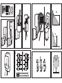
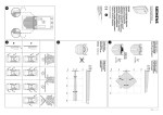
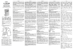
Max. 14 Ct./Min aus dem deutschen Festnetz.
Mobil max. 42 Ct./Min.
International calls may vary.
000926
MA00432602
GEV GmbH
Heidehofweg 16
25499 Tangstedt
Germany
www.gev.de
[email protected]
Hotline: +49 (0)180/59 58 555
11/2014 UW
www.gev.de
Typ: LBM 926
# 000926
C
F
D
H
10 m
A
1m
1
B
E2
E1
1212
V V12 V
1212
V V12 V
I
G
Power
Power
Power
1
2
2
3
90°
120°
90°
Beachten Sie die maximal Lasten!
4
Anschluss Beispiele:
Abb. E1 = Extern gespeiste Klingel
Abb. E2 = Leuchte mit gleicher Spannung wie der Bewegungsmelder LBM. Verbinden Sie die Kabel mit der Anschlussleitung gemäß
Schaltbild (Abb. E). und setzen den Bewegungsmelder auf die
Wandanschlussplatte Abb. F. Schalten Sie die Stromkreissicherung
wieder ein.
Reichweitentest
Stellen Sie den Regler TIME auf Minimum, den Regler LUX auf
„Sonne“ und den Regler METER auf Maximum (Abb. G). Falls
der Bewegungsmelder über einen separaten Schalter angeschlossen ist, schalten Sie ihn ein. Es beginnt ein 15 Sek. andauernder
Selbsttest. In dieser Zeit ist der angeschlossene Verbraucher dauernd eingeschaltet. Wenn sich der Verbraucher ausschaltet, beginnt der Reichweitentest. Der Verbraucher schaltet sich jetzt unabhängig von der Umgebungshelligkeit bei jeder Bewegung für
ca. 5 Sek. an. Diese Zeit beginnt bei jeder Bewegung von vorne.
Dieser Reichweitentest hilft Ihnen, den Erfassungsbereich zu
ermitteln. Der Bewegungsmelder lässt sich horizontal (Abb. I) und
DE
Recycling-Hinweise
Dieses Gerät darf nicht mit dem unsortierten Hausmüll
entsorgt werden. Besitzer von Altgeräten sind gesetzlich
dazu verpflichtet, dieses Gerät fachgerecht zu entsorgen.
Informationen erhalten Sie von Ihrer Stadt- bzw.
Gemeindeverwaltung.
GB
vertikal (Abb. H) ausrichten. Mit dem Regler METER können Sie
zusätzlich die Reichweite einstellen. Nach erfolgreicher Einstellung können Sie weitere Einstellungen vornehmen.
Einstellungen (Abb. G)
LUX Dämmerungsschalter ca. 5 bis 1000 Lux.
TIME Zeiteinstellung für die Einschaltdauer ca. 5 Sek.- 15 Min.
Störung
Bewegungsmelder schaltet zu spät
Maximale Reichweite wird nicht
erreicht
Bewegungsmelder schaltet ständig
oder unerwünschtes Schalten
Keine Reaktion bei Fahrzeugen
Ursache
•Einstellung Erfassungsbereich
•Bewegung frontal
•Bewegungsmelder zu niedrig angebracht
•Temperaturdifferenz von Umgebung zur Wärmequelle ist zu gering
•Ständige Wärmebewegungen: In den Erfassungsbereich fallen Bereiche, die nicht erfasst werden sollen, wie z. B. Gehwege, Straßen, Bäume reflektierendes Wasser u.s.w. Unerwartete Veränderungen von Wärmequellen durch Sturm, Regen oder Ventilatoren. Beeinflussung durch Sonneneinstrahlung direkt/indirekt
•Fahrzeug nicht warmgefahren
•Motorbereich ist stark isoliert
Abhilfe
•Erfassungsbereich durch Drehen des
Sensors einstellen
•Höher montieren
•Bewegungsmelder neu Ausrichten, ggf.
•Montage Ort ändern
Technische Daten
Erfassungsbereich120°
Zeiteinstellung
ca. 5 Sek. - 15 Min. stufenlos einstellbar
Reichweite
ca. 1 m bis ca. 10 m abhängig von der Montagehöhe und Außentemperatur
Dämmerungsschalter
ca. 5 - 1000 Lux stufenlos einstellbar
Schaltleistung potenzialfreies Relais 10 A, 12 V bis 30 V
Spannungsanschluss
12 V
Schutzart
IP 44
Empfohlene Montagehöhe ca. 2,5 m
Abmessungen
ca. B 100 x H 80 x T 117 mm
Technische und optische Änderungen ohne Ankündigung vorbehalten.
5
FR
Fehleranalyse – Praktische Tipps
IT
Installation
Der Bewegungsmelder LBM kann sowohl an Wände als auch
an Decken montiert werde (Abb. A). Je nach Montageart und
Einstellbereich eines der vorgestanzten Löcher ausbrechen
(Abb. B1 oder Abb. B2). Führen Sie die Kabel und das Gewinde des
Bewegungsmelderkopfes in das Loch und befestigen diese mittels
Unterlegscheibe und Mutter (Abb. C). Führen Sie das Anschlusskabel durch die Gummi Tülle Abb. D1 und montieren die Wandanschlussplatte gemäß Abb. D. Der Bewegungsmelder LBM verfügt
über ein potentialfreies Relais, zur Schaltung von Leuchten oder
anderen Geräten.
PL
Bewegungsmelder 12 Volt LBM 926, 120°
Arbeitsweise
Der Bewegungsmelder arbeitet nach dem Prinzip der PassivInfrarot-Technik. Über einen PIR-Sensor nimmt der Bewegungsmelder in seinem Erfassungsbereich sich bewegende Wärmequellen wahr und schaltet die angeschlossenen Verbraucher automatisch ein. Ruhende Wärmequellen schalten den
Bewegungsmelder nicht ein. Der einstellbare Dämmerungsschalter sorgt dafür, dass der Bewegungsmelder wahlweise bei Tag
und Nacht oder nur bei Dunkelheit arbeitet. Mit dem eingebauten
Timer wird die Einschaltdauer des angeschlossenen Verbrauchers
eingestellt.
Sicherheitshinweise
Die Montage darf nur von einem Fachmann unter Berücksichtigung der landesüblichen Installationsvorschriften ausgeführt werden. Es darf nur in spannungsfreiem
Zustand gearbeitet werden, dazu unbedingt die Stromkreissicherung abschalten.
Überprüfen Sie, ob die Anschlussleitung spannungsfrei ist!
Bei Schäden, die durch Nichtbeachtung dieser Bedienungsanleitung verursacht werden, erlischt der Garantieanspruch! Für
Folgeschäden übernehmen wir keine Haftung! Bei Sach- oder
Personenschäden, die durch unsachgemäße Handhabung oder
Nichtbeachtung der Sicherheitshinweise verursacht werden, übernehmen wir keine Haftung. In solchen Fällen erlischt jeder Garantieanspruch. Aus Sicherheits- und Zulassungsgründen ist das eigenmächtige Umbauen und/oder Verändern des Gerätes nicht gestattet.
Montageort
Die sicherste Bewegungserfassung wird erzielt, wenn man
sich quer zum Bewegungsmelder bewegt. Daher sollte ein
Bewegungsmelder immer so montiert werden, dass man sich nicht
direkt auf ihn zu bewegt.
Connection: Examples
Fig. E1 = Externally powered doorbell
Fig. E2 = Lights with the same voltage as the LBM motion detector.
Connect the cable to the power supply line according to the circuit
diagram (Fig. E) and place the detector on the wall connection plate
Fig. F. Switch the circuit protection back on.
Range test
Set the TIME controller to minimum, the LUX controller to “sun”
and the METER controller to maximum (fig. G). If the detector is
switched on via a separate switch, turn this on. A self-test is then
initiated lasting approx. 15 seconds. The connected device will
remain on throughout this time. When the device turns off, the range
test will begin. The device will now switch on for approx. 5 seconds
in response to any movement, regardless of the ambient lighting
level. This time period is initiated by any movement from the front.
This range test is designed to help you to determine the field of
detection. The motion detector can be adjusted horizontally (fig. I)
and vertically (fig. H). The METER controller also allows you to set
the range. Once this has been adjusted successfully you will be able
to make further settings.
Settings (fig. G)
LUX Twilight switch approx. 5 to 1000 lux
TIME Time setting for the ON period approx. 5 sec. – 15 min.
6
Troubleshooting – Practical tips
Problem
Cause
Remedy
Motion detector switches
• Detection range setting
• Adjust detection area by
the light on too late
• Movement from the front
turning the sensor
Motion detector fails to
• Motion detector is mounted too low
• Mount higher
achieve maximum range
• Difference in temperature between heat source
and surroundings is not big enough
Motion detector switches
• Constant warm movement: • Re-align detector and, if necessary,
light on constantly The field of detection encompasses areas change its location
or when not necessary that do not require monitoring, such as pathways,
roads, trees and reflective water.
Unexpected change in heat sources due to a
storm, rain or fans.
Influence of direct/indirect sunlight
Fails to react to vehicles
• Vehicle has not warmed up
• Engine area is very well insulated
Technical data
Field of detection120°
Time adjustment
approx. 5 sec. - 15 min., infinitely variable
Range
approx. 1 m to approx. 10 m depending on installation height
and outside temperature
Twilight switch
approx. 5 - 1000 lux, infinitely variable
Switching capacity floating relais 10 A, 12 V to 30 V
Power supply connections
12 V
Protection type
IP 44
Recommended installation height
approx. 2.5 m
Dimension
approx. H 100 x W 80 x D 117 mm
Subject to technical and design changes without prior notice.
7
DE
GB
contain substances which are harmful to the environment and to
human health and must therefore be disposed of correctly.
FR
Check maximum loads!
Recycling instructions
Used batteries must not be disposed of as unsorted
household waste. Used batteries must be recycled and may
be returned free-of-charge to the place of sale. Batteries
IT
(fig. B1 or fig. B2). Guide the cable and the thread of the detector
head into the hole and secure using a washer and nut (fig. C). Guide
the connecting cable through the rubber grommet fig. D1 and mount
the wall connection plate according to fig. D. The LBM motion
detector has a floating relay for switching lights or other devices.
Operation
The motion detector operates using passive infrared technology. Via
a PIR sensor, the detector notices any heat sources moving within
its field of detection and switches on automatically. Static heat
sources do not trigger it. The adjustable twilight switch lets you
choose whether you have the motion detector working day and night
or only when it is dark. The integrated timer also lets you adjust how
long the light stays on.
Safety information
To be fitted by qualified electricians only, observing all
standard national installation regulations.
No work to be carried out while live. The circuit trip switch
must therefore be switched off.
Check to make sure the connecting cable is not live!
All warranty claims will be null and void in the event of
any damage or loss caused by failure to observe these
operating instructions. We accept no liability for any consequential
losses or damage. We accept no liability for any personal injury or
material damage caused by improper use or by failure to observe
the safety advice.
In such cases all warranty claims will be null and void. For reasons
of safety and approval, no unauthorised conversion and/or
modification of the appliance is allowed.
Where to install
The motion detector is at its most effective when approached
diagonally. Motion detectors should therefore always be set up so
that they are not directly approached.
Installation
The LBM motion detector can be mounted either on a wall or on a
ceiling (fig. A). Unplug one of the pre-punched holes that is most
suitable for the type of installation and the programmable range
PL
Motion detector 12 volt LBM 926, 120°
Veillez à respecter la charge maximale !
Alimentation : Exemples
Fig. E1 = sonnette à alimentation externe
Fig. E2=luminaire avec une tension identique au détecteur de
mouvement LBM. Raccordez les câbles conformément au schéma
électrique (fig. E), puis positionnez le détecteur de mouvement sur
l‘embase de raccordement murale (fig. F). Remettez en place le
fusible secteur.
Test de la portée
Positionnez la molette TIME sur minimum, la molette LUX sur
le symbole „soleil“ et la molette METER sur maximum (fig. G).
Si le détecteur de mouvement est raccordé à un interrupteur,
assurez-vous que celui-ci est en position d‘allumage. Le système
procède à un test automatique d‘une durée de 15 secondes.
Pendant le test, l‘appareil raccordé reste allumé. Lorsqu‘il s‘éteint, un
test de portée démarre. À présent, en cas de mouvement, l‘appareil
s‘active pendant 5 secondes environ, indépendamment de la
uminosité ambiante (à chaque mouvement, le luminaire se rallumera
pendant 5 secondes). Ce test de portée vous permet de définir la
zone de détection. Le détecteur de mouvement peut être orienté
8
DE
Remarques concernant le recyclage
Cet appareil ne doit en aucun cas être jeté avec les ordures
ménagères. Les propriétaires d’équipements électriques ou
électroniques usagés ont en effet l’obligation légale de les
déposer dans un centre de collecte sélective. Informez-vous sur
les possibilités de recyclage auprès de votre municipalité.
GB
horizontalement (fig. I) et verticalement (fig. H). La molette
METER vous permet en outre de définir la portée. Une fois ce
paramétrage effectué, vous pouvez procéder à d‘autres réglages.
Réglages (fig. G)
LUX Interrupteur crépusculaire de 5 à 1000 lux env.
TIME Réglage de la durée d‘allumage entre 5 s et 15 min
IncidentCause
Remède
Détecteur de mouvements
• Réglage de la zone de détection
• Régler la zone de détection en
commute à retardement
• Déplacement frontal
tournant le senseur
La portée maximale n‘est • Le détecteur est monté trop bas
• Montage plus haut
pas atteinte
• La différence entre la température ambiante et la
source de chaleur est trop faible
Détecteur de mouvements
• Agitation thermique constante :
• Réorienter le détecteur de
commute en permanence ou la zone de détection contient des éléments impossibles à surveiller, mouvement, ou choisir un
commutation non souhaitée telles qu‘un trottoir, une rue, des arbres, des reflets sur de l‘eau, etc. autre emplacement
Modification inattendue des sources de chaleur à cause du vent,
de la pluie ou de ventilateurs.
Interférence liée à un ensoleillement direct/indirect
Pas de réaction au • Moteur de véhicule pas encore chaud
passage de véhicule
• Moteur comportant une forte isolation
Caractéristiques techniques
Zone de détection Réglage de délai
Portée
Interrupteur crépusculaire Puissance de commutation
Raccordement électrique
Type de protection
Hauteur de montage recommandée
Dimensions
120°
environ 5 s à 15 min, réglage en continu
1 m à 10 m env. selon la hauteur de montage et la température extérieure
environ 5 à 1000 Lux, réglage en continu
sec relais 10 A, 12 V - 30 V
12 V
IP 44
environ 2,5 m
environ H 100 x I 80 x P 117 mm
Modifications techniques et optiques réservées sans avertissement préalable.
9
FR
Analyse d‘incidents – Conseils pratiques
IT
Installation
Le détecteur de mouvement LBM se fixe aussi bien au mur qu‘au
plafond (fig. A). Détachez l‘une des languettes prédécoupées, selon
le type de montage et la zone de détection souhaitée (fig. B1 ou
fig. B2). Introduisez dans l‘orifice les câbles et le filetage de la tête
du détecteur, puis fixez-les au moyen de la rondelle et de l‘écrou
(fig. C). Insérez le câble de raccordement à l‘aide de l‘embout en
caoutchouc (fig. D1) et montez l‘embase de raccordement murale
(fig. D). Le détecteur de mouvement LBM est doté d‘un relais à contact
sec servant au branchement de luminaires ou d‘autres appareils.
PL
Détecteur de mouvement 12 V LBM 926, 120°
Fonctionnement
Le détecteur de mouvement travaille suivant le principe de la
technique infrarouge passive. Par l‘intermédiaire d‘un senseur PIR,
le détecteur de mouvement détecte les sources de chaleur en
mouvement dans son rayon d‘action, et commute automatiquement
un appareil. Les sources de chaleur immobiles ne font pas réagir
le détecteur. L‘interrupteur crépusculaire réglable fait en sorte que
le détecteur de mouvement travaille au choix le jour et la nuit ou
uniquement dans la pénombre. La minuterie intégrée détermine la
durée de fonctionnement.
Consignes de sécurité
Le montage doit être réalisé uniquement par un
spécialiste qui tiendra compte des directives national
habituelles de montage. Les travaux doivent être
exécutés uniquement hors tension, pour cela il faut
absolument débrancher les fusibles de protection du circuit secteur.
Vérifier si le câble de raccordement est bien hors tension !
Les recours en garantie sont supprimés en cas de dommages
causés par le non-respect des présentes instructions ! Nous
déclinons toute responsabilité pour les conséquences de
dommages ! Nousdéclinons toute responsabilité pour les
dommages sur les personnes ou les biens qui sont la conséquence
d‘une manipulation incorrecte ou de non-respect des consignes
de sécurité. Dans ces cas également la garantie n‘est plus en
vigueur. Pour des raisons de sécurité et d‘autorisation il est interdit
d‘apporter des modifications quelconques sur l‘appareil.
Lieu de montage
On obtient la meilleure détection quand les déplacements se font
perpendiculairement au détecteur. C‘est pourquoi le détecteur de
mouvement devrait toujours être monté de telle sorte que les
personnes ne se déplacent pas face au détecteur.
10
Collegamento: Esempi
Fig. E1 = Campanello alimentato dall’esterno
Fig. E2=Lampade con la medesima tensione del rilevatore di
movimento LBM. Collegare il cavo all‘alimentazione come indicato
nello schema elettrico (fig. E) e posizionare il rilevatore di
movimento nella piastra di fissaggio a parete fig. F. Inserire
nuovamente l’interruttore automatico del circuito elettrico.
Test del raggio di azione
Posizionare il regolatore TIME nella posizione di minimo, il regolatore
LUX su „Sole“ e il regolatore METER nella posizione di massimo
(fig. G). Nel caso il sensore di movimento sia collegato tramite
interruttore separato, questo deve essere inserito. Inizierà un
autotest della durata di ca. 15 secondi. In questo lasso di
tempo l‘utenza collegata è costantemente attivata. Quando il
dispositivo collegato si spegne, viene avviato il test del raggio di
azione. Il dispositivo si accende per circa 5 secondi quando rileva
un movimento, indipendentemente dalla luminosità dell’ambiente.
Questa temporizzazione riparte ad ogni movimento. Questo test del
raggio di azione è utile per stabilire l’angolo di copertura. Il rilevatore
di movimento può essere installato orizzontalmente (fig. I) o
verticalmente (fig. H). Utilizzando poi il regolatore METER sarà
possibile regolare la portata. Una volta terminata la regolazione con
successo, è possibile procedere ad altre impostazioni.
Analisi degli errori – Suggerimenti pratici
AnomaliaCausa
Rimedio
Il sensore di movimento
• Impostazione del campo di rilevamento
•Impostare il campo di rilevamento
interviene troppo tardi
• Movimento frontale
ruotando il sensore
La portata massima non • Il sensore di movimento è stato montato troppo basso
•Montare il sensore più in alto
viene raggiunta
• La differenza di temperatura fra l´ambiente e la fonte
di calore è troppo bassa
Il sensore di movimento
• Movimento del calore costante:
•Riposizionare il rilevatore di movimento,
si accende in modo Nell’area di rilevamento sono presenti elementi che ovvero cambiare il luogo di installazione
continuo o in modo non devono essere rilevati, come ad esempio sentieri,
inopportuno strade, alberi acqua riflettente, ecc.
Cambiamento imprevisto delle fonti di calore a causa
di tempeste, pioggia o ventilatori. Interferenza causata dalla
radiazione solare diretta o indiretta
Nessuna reazione in caso • Veicolo non caldo
di veicoli
• Il vano motore è fortemente isolato
Dati tecnici
Campo di rilevamento 120°
Impostazione dell‘ora
regolabile in modo continuo da 5 sec. a 15 min.
Portata
da 1 m a 10 m circa in base all’altezza di installazione e alla temperatura esterna
Interruttore crepuscolare 5 - 1000 Lux circa, regolazione continua
Potenza di interruzione
potenziale zero relais 10 A, 12 V to 30 V
Alimentazione
12 V
Grado di protezione
IP 44
Altezza di montaggio consigliata
circa 2,5 m
Dimensioni
circa H 100 x L 80 x P 117 mm
La ditta si riserva il diritto di apportare variazioni tecniche ed estetiche senza preavviso.
11
DE
GB
Indicazioni per il riciclaggio
Questo dispositivo non deve essere smaltito come rifiuto
indifferenziato. Chi possiede un vecchio dispositivo è
vincolato per legge allo smaltimento conformemente
alle normative in vigore. Per ulteriori informazioni rivolgersi
all’amministrazione comunale.
FR
Prestare attenzione al carico massimo!
Impostazioni (fig. G)
LUX Interruttore crepuscolare da 5 a 1000 Lux ca.
TIME Impostazione del tempo di accensione, 5 secondi - 15
minuti ca.
IT
Introdurre il cavo e la filettatura del rilevatore nel foro e fissarli con
una rondella e un dado (fig. C). Inserire il cavo di alimentazione
attraverso l’anello in gomma fig. D1 e montare la piastra di fissaggio
a parete come da fig. D. Il rilevatore di movimento LBM dispone
di un relè a potenziale zero per commutazione di lampade o altri
dispositivi.
PL
Rilevatore di movimento 12 Volt LBM 926, 120°
Funzionamento
Il sensore di movimento funziona secondo il principio della tecnica
passiva a infrarossi. Con un sensore PIR, il sensore di movimento
percepisce nel proprio campo di rilevamento eventuali fonti di
calore in movimento e interviene automaticamente. Il sensore di
movimento non interviene in presenza di fonti di calore
statiche. L‘interruttore crepuscolare regolabile fa sì che il sensore di
movimento funzioni, a scelta, di giorno e di notte oppure solo in caso
di buio. Il rapporto d‘inserzione viene impostato con il timer incorporato.
Indicazioni di sicurezza
Il montaggio deve essere eseguito solo da un tecnico
specializzato che rispetti le norme di installazione locali.
assenza di tensione, staccando in ogni caso il fusibile del
circuito elettrico. Verificare che la linea sia priva di tensione!
La garanzia decade in caso di danni dovuti alla mancata
osservanza delle presenti istruzioni per l‘uso. Non ci assumiamo alcuna
responsabilità per danni consequenziali. Non ci assumiamo alcuna
responsabilità in caso di danni a cose o a persone causati da un
utilizzo inadeguato o dalla mancata osservanza delle indicazioni di
sicurezza. In tali casi qualunque garanzia decade. Per motivi di
sicurezza e di omologazione, non è consentito smontare e/o
modificare di propria iniziativa l‘apparecchiatura.
Posizione di montaggio
È possibile ottenere un rilevamento più sicuro di ogni movimento se
quest‘ultimo ha luogo in direzione trasversale rispetto al sensore di
movimento. Pertanto, montare sempre il sensore di movimento in
modo che il moto non abbia luogo verso di esso.
Installazione
Il rilevatore di movimento LBM può essere montato sia a parete
sia a soffitto (fig. A). In base al tipo di installazione e al campo
di regolazione, aprire uno dei fori prefratturati (fig. B1 o fig. B2).
Należy uważać na maksymalne obciążenia!
12
Przykłady połączeń:
Rys. E1 = dzwonek z zasilaniem zewnętrznym
Rys. E2 = lampa na to samo napięcie, co czujka ruchu LBM. Podłącz
kabel z przewodem łączeniowym zgodnie ze schematem (rys. E) i
nasadź czujkę ruchu na ścienną płytkę łączeniową (rys. F). Włącz z
powrotem zabezpieczenie obwodu prądowego.
Test zasięgu
Ustaw regulator TIME na minimum, regulator LUX na „słońce”, a
regulator METER na maksimum (rys. G). Jeśli czujka ruchu jest
podłączona przez oddzielny wyłącznik, włącz go. Rozpoczyna się
test samoczynny trwający ok. 15 sekund. W tym czasie podłączony
odbiornik jest przez cały czas włączony. Po wyłączeniu odbiornika
rozpoczyna się test zasięgu. Odbiornik załącza się teraz przy każdym
poruszeniu, niezależnie od jasności otoczenia, na ok. 5 sekund. Czas
ten biegnie od początku przy każdym poruszeniu. Test zasięgu pozwala
każdemu użytkownikowi indywidualnie wyznaczyć obszar detekcji.
Położenie czujki ruchu można zmieniać w poziomie (rys. I) i w pionie
(rys. H). Regulator METER umożliwia dodatkowo regulację zasięgu. Po
pomyślnym dokonaniu ustawień możesz dokonać kolejnych ustawień.
Usterka
Czujka ruchu zbyt późno się włącza
Przyczyna
•Ustawienie obszaru detekcji
•Ruch na wprost
Nie jest uzyskiwany maksymalny zasięg •Czujka ruchu zamocowana zbyt nisko
•Zbyt mała różnica temperatury pomiędzy otoczeniem
a źródłem ciepła
Czujka ruchu załącza się ciągle lub w
•Nieprzerwany ruch ciepła: W obszarze detekcji znajdują się
niepożądany sposób
obszary, które nie powinny być nią objęte, np. ścieżka, ulica, drzewa, tafla wody odbijająca światło itd. Nieoczekiwane zmiany właściwości źródeł ciepła w wyniku burzy, deszczu lub wentylatorów. Bezpośrednie lub pośrednie oddziaływanie
promieni słonecznych
•Pojazd nie jest rozgrzany
Brak reakcji na pojazdy
•Obszar silnika jest mocno izolowany
Dane techniczne
Obszar detekcji
Ustawienie czasu
Zasięg
Wyłącznik zmierzchowy
Moc łączeniowa Przyłącze napięcia
Stopień ochrony
Zalecana wysokość montażu
Wymiary
Rozwiązanie
•Ustaw obszar detekcji obracając
czujnikiem
•Montaż wyżej
•Ustaw na nowo czujkę ruchu, w razie
potrzeby
•zmień miejsce montażu
120°
ok. 5 s – 15 min, regulowane bezstopniowo
ok. 1 m do 10 m w zależności od wysokości montażu i temperatury zewnętrznej
ok. 5 – 1000 lx, regulowany bezstopniowo
przekaźnik z galwaniczną separacją styków 10 A, 12 V do 30 V
12 V
IP 44
około 2,5 m
ok. 100 x 80 x 117 mm (szer. x wys. x głęb.)
Zastrzega się możliwość wprowadzania zmian technicznych i wizualnych bez wcześniejszego powiadomienia.
13
DE
GB
Analiza błędów — wskazówki praktyczne
Uwagi dotyczące recyklingu
Niniejszego urządzenia nie wolno usuwać razem z
niesortowanymi
odpadami
domowymi.
Posiadacze
zużytego sprzętu są ustawowo zobowiązani do zapewnienia
prawidłowej utylizacji urządzeń. Odpowiednie informacje można
uzyskać u odpowiednich władz miejskich lub gminnych.
FR
Ustawienia (rys. G)
LUX przełącznik zmierzchowy ok. 5 – 1000 lx.
TIME Ustawienie czasu załączenia oświetlenia ok. 5 s. – 15 min.
IT
Instalacja
Czujkę ruchu LBM można montować zarówno na ścianach, jak
i na sufitach (rys. A). W zależności od rodzaju montażu i zakresu
regulacji, należy wyłamać jeden ze wstępnie wytłoczonych otworów
(rys. B1 lub rys. B2). Wprowadź kabel i gwintowaną końcówkę
głowicy czujki ruchu w otwór i zamocuj je przy użyciu podkładki i
nakrętki (rys. C). Przeprowadź kabel łączeniowy przez gumową
tuleję (rys. D1) i zamontuj ścienną płytkę łączeniową zgodnie z
rys. D. Czujka ruchu LBM jest wyposażona w przekaźnik separowany
galwanicznie, umożliwiający przełączanie opraw oświetleniowych
lub innych urządzeń.
Sposób działania
Czujki ruchu działają według zasady biernej techniki podczerwieni.
Bierny czujnik podczerwieni powoduje wykrywanie przez czujkę
ruchu w zakresie detekcji poruszających się źródeł ciepła i
automatyczne załączenie dołączonego odbiornika. Nieruchome
źródła ciepła nie załączają czujki ruchu. Regulowany wyłącznik
zmierzchowy zapewnia wybór możliwości pracy: w dzień i w nocy
lub tylko w ciemności. Wbudowany wyłącznik czasowy umożliwia
ustawienie czasu załączenia dołączonego odbiornika.
Uwagi dotyczące bezpieczeństwa
Montaż może być wykonywany wyłącznie przez specjalistę,
przy przestrzeganiu obowiązujących w danym kraju
przepisów dotyczących instalacji elektrycznych. Dozwolona
jest wyłącznie praca przy odłączonym napięciu. W tym celu należy
bezwzględnie rozłączyć bezpiecznik obwodu prądowego.
Sprawdź, czy w przewodzie podłączeniowym nie ma napięcia!
W przypadku szkód spowodowanych nieprzestrzeganiem
niniejszej instrukcji obsługi gwarancja wygasa! Za szkody wtórne
nie przyjmujemy żadnej odpowiedzialności! Nie przyjmujemy
odpowiedzialności w przypadku szkód rzeczowych i obrażeń
ciała spowodowanych nieumiejętnym postępowaniem lub
niestosowaniem się do uwag związanych z bezpieczeństwem. W
takich przypadkach wszelkie roszczenia gwarancyjne wygasają.
Z przyczyn związanych z bezpieczeństwem i dopuszczeniami
technicznymi, samowolne przeróbki lub modyfikacje urządzenia są
niedozwolone.
Miejsce montażu
Najbardziej pewne wykrywanie ruchu można uzyskać, poruszając
się poprzecznie względem czujki ruchu. Z tego powodu czujkę ruchu
należy zawsze montować tak, aby nie poruszać się bezpośrednio w
jej stronę.
PL
Czujka ruchu 12 V LBM 926, 120°