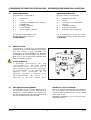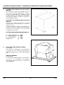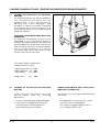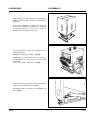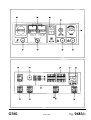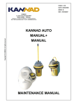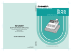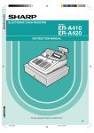
1
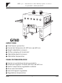
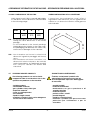
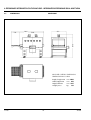
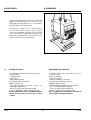
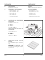
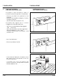
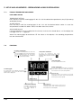
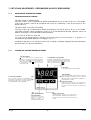
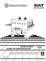
R
SHRINK TUNNEL
TUNNEL PER TERMORETRAZIONE
GT60
Type A
INSTRUCTIONS MANUAL AND SPARE PARTS LIST
MANUALE DI ISTRUZIONI E PARTI DI RICAMBIO
English edition
Edizione Italiana
Cod. pubbl.: 3.0.01759.02A
R
Manuale di istruzioni per l'uso, la sicurezza, la
manutenzione e le parti di ricambio del tunnel di
termoretrazione GT60 tipo A.
Instruction manual for the use, safety,
maintenance and spare parts concerning the
machine model GT60 Type A.
Pubblicazione di proprietà della Siat S.p.A.
Via Puecher, 22 - 22078 TURATE (CO) - ITALY
Tel. 02-964.951 - Fax 02-9689727
This publication is property of SIAT S.P.A.
Via Puecher, 22 - 22078 TURATE (CO) - ITALY
Tel. 02-964951 - Fax. 02-9689727
Edizione Febbraio 2002
Edition February 2002
Vietata la riproduzione. Tutti i diritti riservati
© Siat S.p.A. 2002.
The reproduction of this manual is strictly
forbidden. All rights reserved © Siat S.p.A. 2002.
il fabbricante si riserva di apportare modifiche alle
macchine senza preavviso.
The manufacturer reserves the right to modify the
product at any time without notice.
Pubblicazione n° 3.0.01752.02A
Revisione I
Publication n. 3.0.01752.02A
Release I
GT60
2
A0202
siat S.p.A. - Via Puecher, 22 - 22078 TURATE (CO) ITALY - P.O. BOX 1
Tel. (02) 964951 - Telefax (02) 9689727
GT60
SHRINK TUNNEL
●
●
●
●
●
●
Total thermic protection
Tunnel inlet dimensions: h. 320 mm x w. 600 mm
Height adjustable conveyor
Air flow swinging at tunnel inlet
Adjustable speed conveyor
Adjustable temperature
TUNNEL PER TERMORETRAZIONE
●
●
●
●
●
●
Tunnel con protezione termica completa
Dimensioni ingresso tunnel h. 320 mm x w. 600 mm
Nastro trasportatore regolabile in altezza
Flusso aria orientabile
Velocità tappeto regolabile
Regolazione temperatura
A0202
3
GT60
INDICE
INDEX
Sezione
Section
Manufacturing specifications
1.1
Norme costruttive
1.1
Manual, how to use it
1.2
Manuale, come utilizzarlo
1.2
Serial Number
2.1
Numero di matricola
2.1
After-sale service
2.2
Assistenza tecnica
2.2
Warranty
2.3
Garanzia
2.3
Safety
3
Sicurezza
3
Operators' skill levels
3.6
Qualifiche operatori
3.6
Technical specifications
4.2
Dati tecnici
4.2
Dimensions and weight
4.6
Dimensioni e pesi
4.6
Noise measurement
4.9
Rumorosità
4.9
Transportation
5
Trasporto
5
Unpacking
6
Disimballo
6
Installation
7
Installazione
7
Controls
8
Comandi
8
Theory of operation
9
Funzionamento
9
Safety devices
10
Dispositivi di sicurezza
10
Set-up and adjustments
11
Preparazione all'uso e regolazioni
11
Operation
12
Uso della macchina
12
Cleaning
12.4
Pulizia
12.4
Trouble shooting
12.7
Diagnosi inconvenienti
12.7
Maintenance
13
Manutenzione
13
Lubrication
13.4-13.5
Lubrificazione
13.4-13.5
Furnace cleaning
13.6
Pulizia forno
13.6
Equipment cleaning
13.7
Pulizia macchina
13.7
Motor thermic switch reset
13.8
Ripristino termica motore
13.8
Log of maintenance work
13.10
Registro interventi di manutenzione 13.10
Fire emergency
14.2
Incendio
14.2
Enclosures
15
Allegati
15
Electric Schema
16.1
Schema elettrico
16.1
Spare parts
last section
Ricambi
in fondo al manuale
GT60
4
A0202
ABBREVIATIONS AND ACRONYMS
ABBREVIAZIONI E SIGLE
LIST OF ABBREVIATIONS, ACRONYMS AND UNUSUAL
TABELLA DELLE ABBREVIAZIONI, SIGLE
TERMS TO BE FOUND IN THIS MANUAL
E TERMINI NON DI USO COMUNE UTILIZZATI
NEL MANUALE
Dwg.
= drawing
Dis.
= Disegno
Encl.
= enclosure
All.
= Allegato
Ex.
= example
Es.
= Esempio
Fig.
= figure showing spare parts
Fig.
= Figura ricambi
Max.
= maximum
Max.
= Massimo
Min.
= minimum
Min.
= Minimo/a
Mod.
= machine model
Mod.
= Modello della macchina
N.
= number
N.
= Numero
N/A
= not applicable
N/A
= Non si applica (Not Applicable)
OFF
= machine stopped
OFF
= Macchina ferma
ON
= machine running
ON
= Macchina in moto
OPP
= oriented polypropylene adhesive tape
OPP
= Polipropilene Orientato
PLC
= Programmable Logic Control
PLC
= Programmable Logic Control
PP
= polypropylene
(Apparecchiatura di controllo a
PTFE
= Polytetrafluorethylene
logica programmabile)
PVC
= Polyvinylchloride
PP
= Polipropilene
Ref.
= reference mark
PTFE
= Politetrafluoroetilene
SIAT SPA
= Società Internazionale Applicazioni
PVC
= Polivinilcloruro
Ric.
= Richiami
SIAT SpA
= Società Internazionale Applicazioni
Tecniche (Società per Azioni)
Tav.
= Illustration
Tecniche (Società per Azioni)
Tav.
= Tavola illustrata
w
= width
w
= Larghezza
h
= height
h
= Altezza
l
= length
l
= Lunghezza
A0202
5
GT60
1-INTRODUCTION
1-PREMESSE
1.1
MANUFACTURING SPECIFICATIONS
NORME COSTRUTTIVE
The Shrink Tunnel Mod. GT 40 has been
designed and manufactured following the
"Machine Directives 89/392" and subsequent
revisions, in compliance with the legal
requirements at the date of inception.
Il tunnel per termoretrazione mod. GT 40 è
stato progettato e costruito secondo la
Direttiva Macchine CEE 89/392 rispondendo
ai requisiti richiesti dalla legislazione alla data
di costruzione.
THE REFERENCE DOCUMENTS ARE:
89/392/CEE
91/368/CEE
93/44/CEE
93/68/CEE
89/336/CEE
I DOCUMENTI DI RIFERIMENTO SONO:
89/392/CEE
91/368/CEE
93/44/CEE
93/68/CEE
89/336/CEE
The following specifications have been carried
out, too:
Inoltre sono state applicate le seguenti norme
armonizzate:
EN 292 1^ 1991, September
EN 292 2^ 1991, September
EN 60335-1 1988, June
EN 60204-1 1993, September
EN 292 1^ Sett. 1991
EN 292 2^ Sett. 1991
EN 60335-1 Giugno 1988
EN 60204-1 Sett. 1993
HOW TO READ AND USE THE INSTRUCTION
MANUAL
COME LEGGERE E UTILIZZARE IL MANUALE
ISTRUZIONI
1.2.1 IMPORTANCE OF THE MANUAL
The manual is an important part of the
machine; all information contained herein is
intended to enable the equipment to be
maintained in per fect condition and
operated safely.
Ensure that the manual is available to all
operators of this equipment and is kept up to
date with all subsequent amendments.
Should the equipment be sold or disposed
of, please ensure that the manual is passed
on.
Electrical and pneumatic diagrams are
included in the manual. Equipment using
PLC controls and/or electronic components
will include relevant schemas or programmes
in the enclosure, and in addition the relevant
documentation will be delivered separately.
IMPORTANZA DEL MANUALE
Il manuale è parte integrante della
macchina, le informazioni in esso contenute
vi aiuteranno a mantenere la vostra
macchina in per fette condizioni ed a
lavorare in piena sicurezza.
Custodire il manuale per tutta la durata del
prodotto.
Assicurarsi che qualsiasi emendamento
pervenuto sia incorporato nel testo.
Passare il manuale a qualsiasi utente o
successivo proprietario della macchina.
Gli schemi elettrici e pneumatici sono
normalmente allegati al manuale.
Per le macchine più complesse dotate di
PLC o di elettronica dedicata, gli schemi
possono essere attaccati al quadro
comandi o consegnati a parte.
1.2
GT60
6
A0202
1-INTRODUCTION
1-PREMESSE
1.2.2 MANUAL MAINTENANCE
Keep the manual in a clean and dry place
near the machine. Do not remove, tear or
rewrite parts of the manual for any reason.
Use the manual without damaging it.
In case the manual has been lost or
damaged, ask your after sale service for a
new copy, quoting the code number of the
document.
CONSERVAZIONE DEL MANUALE
Conservare il manuale in luogo pulito e
asciutto, a portata di mano, vicino alla
macchina.
Non asportare, strappare o riscrivere per
alcun motivo parti del manuale
Usare il manuale senza danneggiarlo.
In caso di perdita o danneggiamento,
richiedere una copia al proprio servizio
assistenza/ricambi citando il codice
documento.
1.2.3 CONSULTING THE MANUAL
The manual is composed of:
- pages which identify the document and
the machine pag. 1÷3
- index of the subjects: pag. 4
- instructions and notes on the machine:
sections 2÷14
- enclosures, drawings and diagrams:
sections 15÷16
- spare parts: last section.
All pages and diagrams are numbered. The
spare parts lists are identified by the figure
identification number. All the notes on safety
measures or possible dangers are identified
by the symbol:
CONSULTAZIONE DEL MANUALE
Il manuale è composto da:
- pagine di identificazione del documento
e della macchina: pag. 1÷3;
- indice analitico per argomenti: pag. 4;
- istruzioni e note sulla macchina:
capitoli 2÷14;
- allegati, disegni e schemi: capitoli 15÷16;
- ricambi: in fondo al manuale.
Tutte le pagine e le tabelle sono numerate e
le tavole ricambi sono identificate con il
numero della figura.
Tutte le note sulla sicurezza e su possibili
pericoli sono identificate dal simbolo:
All the notes related to high temperature
dangers are identified by the symbol:
Tutte le note su possibili pericoli di alta
temperatura sono contrassegnate dal
simbolo:
All the important warning notes related to
the operation of the machine are identified
by the symbol:
The parts typed in bold refer to technical
data or technical notes on a specific
subject.
Tutte le note di avvertimento importanti per il
funzionamento della macchina sono
identificati dal simbolo:
Le parti evidenziate in grassetto contengono
particolari riferimenti a caratteristiche o note
tecniche specifiche per l'argomento in
questione.
1.2.4 HOW TO UPDATE THE MANUAL IN CASE OF
MODIFICATIONS TO THE MACHINE
Modifications to the machine are subject to
manufacturer’s internal procedures.
The user receives a complete and up-todate copy of the manual together with the
machine.
Afterwards the user may receive pages or
parts of the manual which contain
amendments or improvements made after
its first publication.
The user must use them to update this
manual.
METODOLOGIA DI AGGIORNAMENTO DEL
MANUALE IN CASO DI MODIFICHE ALLA
MACCHINA
Le modifiche alla macchina sono regolate
da opportuna procedura inter na del
costruttore.
L'utilizzatore riceve il manuale completo e
aggiornato insieme alla macchina e può
ricevere pagine o parti del manuale
contenenti emendamenti successivi alla
prima pubblicazione, che dovranno essere
integrate nel manuale a cura dell'utilizzatore.
☞
☞
A0202
7
GT60
2-INFORMAZIONI GENERALI
2-GENERAL INFORMATION
2.1
R
V
2.2
DATI DI IDENTIFICAZIONE DEL COSTRUTTORE E
DELLA MACCHINA
SERIAL NUMBER OF THE MACHINE AND NAME
OF THE MANUFACTURER
Hz
W
siat group
A
PER ASSISTENZA TECNICA E RICAMBI
RIVOLGERSI
FOR AFTER-SALE SERVICE AND SPARE PARTS
PLEASE APPLY TO:
Siat
AGENT/DISTRIBUTOR OR LOCAL
AFTER SALE SERVICE:
AGENTE/DISTRIBUTORE O SERVIZIO
ASSISTENZA TECNICA LOCALE:
S.p.a
Via Puecher, 22
22078 TURATE (CO) - ITALY
Tel. 02-964951
Fax. 02-9689727
GT60
8
A0202
2-INFORMAZIONI GENERALI
2-GENERAL INFORMATION
2.3
WARRANTY
GARANZIA
Within the limits of what is set forth below, Seller agrees
to repair or replace without cost to Buyer any
defective goods when such defect occurs within a
period of six (6) months from the date in which Seller's
goods have been put into use, but in no event
beyond eight (8) months from the date of shipment.
Expressly excluded from this warranty are those parts
subject to normal wear and tear (by way of illustration,
but not limitation, such parts as belts, rubber rollers,
gaskets, brushes, etc.) and electrical parts.
Buyer must immediately notify Seller of any defect,
specifying the serial number of the machine.
Buyer shall send to Seller the defective item for repair
or replacement. Seller will perform the repairs or
provide a replacement within a reasonable period of
time. Upon effecting such repair or replacement, Seller
shall have fulfilled its warranty obligations. In the event
the repairs or replacement must be effected at the
place where the machine is installed, all expenses for
labor, travel and lodging of Seller's personnel shall be
sustained by the Buyer. Buyer will be invoiced in
conformity with Seller's standard charges for the
services rendered.
Nei limiti di quanto sotto espresso il fornitore si
impegna a riparare tutti gli eventuali difetti di
costruzione che si manifestino durante i sei (6) mesi di
garanzia decorrenti dalla messa in servizio della
macchina, ma comunque non oltre otto (8) mesi
dalla data di spedizione.
Sono espressamente esclusi quei pezzi per i quali è
previsto un normale consumo (come cinghie, rulli in
gomma, guarnizioni, spazzole, etc.) nonché le parti
elettriche.
Per godere della garanzia il cliente deve
immediatamente notificare al fornitore i difetti che si
manifestano, citando il numero di matricola della
macchina. Il committente deve inviare al fornitore il
pezzo difettoso per la riparazione o sostituzione. Il
fornitore eseguirà le riparazioni in un ragionevole
periodo di tempo. Con tale riparazione o sostituzione
il fornitore adempie pienamente ai propri obblighi di
garanzia. Qualora le riparazioni o sostituzioni
debbano essere fatte nel luogo ove la macchina è
installata, le spese di manodopera, viaggio e
soggiorno dei tecnici o montatori saranno
interamente a carico del committente.
Seller is not responsible for defects resulting from:
l fornitore non è responsabile dei difetti derivanti da:
- Improper use of the machine
- Lack of proper maintenance
- Tampering with the machine or repairs effected by
the Buyer.
- Cattivo uso della macchina
- Mancata manutenzione
- Manomissioni o riparazioni eseguite dal
committente.
Seller will not be liable for any injury to persons or things
or for the failure of production. With respect to the
materials not manufactured by Seller, such as motors
and electrical equipment, Seller will grant to Buyer the
same warranty Seller receives from its supplier of such
materials. Seller does not warrant the compliance of its
machines with the laws of non-EEC countries in which
the machines may be installed, nor does it warrant
compliance with laws or standards relating to the
prevention of accidents or pollution. Adaptation of
Seller's machines to the aforesaid laws or standards
shall be the responsibility of Buyer who assumes all
liability therefore. Buyer shall indemnify and hold Seller
harmless against any claim by third parties resulting
from failure to comply with the aforesaid laws and
standards.
Il fornitore non sarà inoltre responsabile di eventuali
danni a persone o cose distinte dalla macchina
oggetto della garanzia, né di eventuale mancata
produzione.
Per i materiali non costruiti dal fornitore, come
apparecchiature elettriche e motori, questi
concede al committente la stessa garanzia che egli
riceve dai fornitori di detti materiali.
Il fornitore non garantisce la conformità delle
macchine alle disposizioni di legge vigenti nei paesi
extra U.E. in cui esse verranno installate ed in
particolare a quelle relative alla prevenzione degli
infortuni ed all'inquinamento. L'adeguamento delle
macchine alle suddette norme è posto a carico del
committente il quale si assume ogni relativa
responsabilità, mandandone indenne il fornitore ed
impegnandosi a sollevarlo da ogni responsabilità a
qualsivoglia pretesa dovesse insorgere da terzi per
effetto dell'inosservanza delle norme stesse.
A0202
9
GT60
3-SAFETY
3-SICUREZZA
3.1
GENERAL SAFETY INFORMATION
AVVERTENZE GENERALI DI SICUREZZA
Read all the instructions carefully before
starting the work with the machine; please
pay particular attention to sections marked
by the symbol
Leggere attentamente tutte le istruzioni
prima di utilizzare la macchina; prestare
particolare attenzione alle sezioni dove si
incontra questo simbolo
3.2
GT60
The GT 60 sealer is equipped with
a STOP EMERGENCY lockable
button, located on the control
board. If it is pressed, it stops the
machine at any point of the
cycle.
Il tunnel per termoretrazione GT 60
dispone di un pulsante STOP
EMERGENZA a ritenuta posto sul
pannello comandi, se premuto
arresta la macchina in qualsiasi punto
del ciclo.
Disconnect the machine from the
mains before any maintenance
operation.
Staccare la spina di alimentazione
dalla presa di corrente prima di ogni
operazione di manutenzione.
Keep this manual in a handy place near the
machine: its information will help you to
maintain the machine in good and safe
working condition.
Conservare questo manuale di istruzioni: le
informazioni in esso contenute vi aiuteranno
a mantenere la vostra macchina in perfette
condizioni ed a lavorare in piena sicurezza.
DEFINITION
OF
QUALIFICATIONS
DEFINIZIONE DELLE QUALIFICHE DEGLI
OPERATORI
THE
OPERATORS'
- Machine operator
- Maintenance technician
- Electrician
- Manufacturer’s technician
-
Only persons who have the skills described in
the following page should be allowed to
work on the machine.
It is the responsibility of the user to appoint
the operators having the appropriate skill
level and the appropriate training for each
category of job.
Il lavoro con la macchina può essere svolto
solo da persone aventi le qualifiche definite
qui di seguito.
Sarà responsabilità dell'utilizzatore definire le
persone qualificate ai vari livelli di intervento
e dare alle stesse l'idoneo addestramento e
le consegne operative come definite in
questo manuale.
10
Operatore conduttore di macchina;
Manutentore meccanico;
Manutentore elettrico;
Tecnico del costruttore
A0202
3-SICUREZZA
3-SAFETY
SKILL 1
QUALIFICA 1
MACHINE OPERATOR
Operator trained and qualified for the
operation of the machine using the control
board, loading the glue into the melter, sizing
the machine, starting, stopping and
restarting the machine in case of interruption
of the cycle with the emergency button.
NOTE: The supervisors of the factory and the
foremen will make sure that the machine
operator has been trained to all operations
before starting to operate the machine.
CONDUTTORE DI MACCHINA
Operatore addestrato e abilitato alla
conduzione della macchina attraverso
l’uso del pulsante di marcia e di tutti i
comandi che regolano il ciclo di lavoro, la
pulizia e l’uso del pulsante stop emergenza a
ritenuta.
NOTA: i responsabili di stabilimento e di
reparto
presteranno
estrema
attenzione che il conduttore macchina
sia stato addestrato a tutte le
operazioni prima di cominciare a
lavorare
con
la
macchina.
SKILL 2
QUALIFICA 2
MECHANICAL MAINTENANCE TECHNICIAN
This operator is trained to use the machine as
the MACHINE OPERATOR and in addition is
able to work with the safety protection
disconnected, to check and adjust
mechanical parts, to carry out maintenance
operations and repair the machine.
He is not allowed to work on live electrical
components.
MANUTENTORE MECCANICO
Tecnico
qualificato
in
grado
di
condurre
la
macchina
come
il
CONDUTTORE MACCHINA e in più di
farla
funzionare
con
protezioni
disabilitate, di intervenire sugli organi
meccanici per regolazioni, manutenzioni, riparazioni.
Non è abilitato a interventi su impianti
elettrici sotto tensione.
SKILL 2a
QUALIFICA 2a
ELECTRICAL MAINTENANCE TECHNICIAN
This operator is trained to use the machine as
the MACHINE OPERATOR and in addition is
able to work with the safety protection
disconnected, to make adjustments, to carry
out maintenance operations and repair the
electrical components of the machine.
He is allowed to work on live electrical
panels, connector blocks, control equipment
etc.
MANUTENTORE ELETTRICISTA
Tecnico
qualificato
in
grado
di
condurre
la
macchina
come
il
CONDUTTORE MACCHINA e in più di
farla
funzionare
con
protezioni
disabilitate,
di
intervenire
sulle
regolazioni e sugli impianti elettrici per
manutenzione
e
riparazione.
Opera
in
presenza
di
tensione
all'interno di quadri elettrici e scatole di
derivazione,
apparecchiature
di
controllo etc.
SKILL 3
QUALIFICA 3
SPECIALIST FROM THE MANUFACTURER
Skilled operator sent by the manufacturer or
its agent to perform complex repairs or
modifications, when agreed with the
customer.
TECNICO SPECIALIZZATO DEL COSTRUTTORE
Tecnico qualificato del costruttore o
del suo rappresentante per operazioni
complesse, quando concordato con
l'utilizzatore.
A0202
11
GT60
3-SAFETY
3-SICUREZZA
3.3
INSTRUCTIONS FOR A SAFE USE OF THE
MACHINE
Only persons who have the skills described
on the following paragraph 3.6 are allowed
to work on the machine.
It is responsibility of the user to appoint the
operators having the appropriate skill level
and the appropriate training for each
category of job.
PRESCRIZIONI PER INTERAGIRE IN MODO
SICURO CON LA MACCHINA
Il lavoro con la macchina può essere svolto
solo da persone aventi le qualifiche definite
al paragrafo 3.6 che segue.
Sarà responsabilità dell'utilizzatore definire le
persone qualificate ai vari livelli di intervento
e dare alle stesse l'idoneo addestramento e
le consegne operative come definite in
questo manuale.
3.4
STATE OF THE MACHINE
List of the modes which are possible with this
machine:
- automatic running;
- running with safety protections removed or
disabled;
- Stop with stop button;
- stopped by using the lockable emergency
stop button;
- electric power disconnected;
STATI DELLA MACCHINA
Elenco degli stati possibili con questa
macchina:
- Marcia automatica;
- Marcia con protezioni ridotte;
- Arresto con pulsante stop;
- Arresto con pulsante di emergenza ritenuto;
- Collegamento elettrico disconnesso;
GT60
12
A0202
3-SAFETY
3.5
NUMBER OF THE OPERATORS
The operations described hereinafter have been analized by the manufacturer; the number
of operators shown for each operation is suitable to perform it in the best way.
A smaller or larger number of operators could be unsafe.
3.6
OPERATORS’ SKILL LEVELS
The table below shows the minimum operator's skill for each operation with the machine.
OPERATION
STATE OF THE MACHINE
OPERATOR'S
SKILL
NUMBER OF
OPERATORS
2 and 2a
2
Installation and set up of the
Running with safety protections
machine.
disabled.
Conveyor speed adjustment.
Running.
1
1
Temperature adjustment.
Running.
1
1
Air stream adjustment.
Running.
1
1
1
1
1
1
2a
1
3
1
3
1
Equipment cleaning.
Electric and pneumatic power
disconnected.
Ordinary maintenance
Electric and pneumatic power
(mechanical).
disconnected.
Ordinary maintenance
Electric and pneumatic power
(electrical).
disconnected.
Extraordinary maintenance
Running with safety protections
(mechanical).
disabled.
Extraordinary maintenance
Running with safety protections
(electrical).
disabled.
A0202
13
GT60
3-SICUREZZA
3.5
NUMERO DEGLI OPERATORI
Le operazioni sotto descritte sono state analizzate dal fabbricante; il numero degli operatori
indicato per ciascuna di esse è adeguato per svolgere la funzione in modo ottimale. Un
numero di operatori inferiore o superiore potrebbe mettere in pericolo la sicurezza del
personale coinvolto.
3.6
QUALIFICA DEGLI OPERATORI
È indicata per ogni operazione la qualifica minima dell'operatore.
QUALIFICA
OPERATORE
NUMERO
OPERATORI
2 e 2a
2
1
1
1
1
1
1
Collegamento elettrico disconnesso.
1
1
Collegamento elettrico disconnesso.
2
1
Collegamento elettrico disconnesso.
2a
1
Marcia con protezioni ridotte.
3
1
Marcia con protezioni ridotte.
3
1
OPERAZIONE
STATO DELLA MACCHINA
Installazione e preparazione
all'uso.
Marcia con protezioni ridotte.
Regolazione velocità
tappeto.
Regolazione della
Marcia.
Marcia.
temperatura.
Regolazione flusso aria.
Pulizia della macchina.
Manutenzione meccanica
ordinaria.
Marcia.
Manutenzione elettrica
ordinaria.
Manutenzione meccanica
straordinaria.
Manutenzione elettrica
straordinaria.
GT60
14
A0202
3-SAFETY
3-SICUREZZA
3.7
RESIDUAL HAZARDS
PERICOLI RESIDUI
The shrink tunnel mod. GT60 has been
designed and manufactured in order to give
the best protection to the operator.
In spite of the precautions taken by the
designers, the essential thing is that the
operator and the maintenance specialists
are infor med of the following residual
hazards which can not be eliminated.
Il tunnel per termoretrazione mod. GT 60 è
stato progettato e costruito in modo di
garantire la massima protezione per
l’operatore.
Nonostante le precauzioni adottate dai
progettisti per la sicurezza, è essenziale che
l’operatore e i tecnici addetti alla
manutenzione siano preventivamente
informati dei seguenti pericoli residui non
eliminabili.
WARNING! Running conveyor.
Do not touch and put your hands into the
running rollers. Danger to be squashed.
ATTENZIONE! Rulliera in movimento.
Non toccare e non inserire le mani nei rulli
quando questi sono in movimento.
Pericolo di schiacciamento.
WARNING! High temperature furnace.
Do not put your hands inside the safety
curtain once the machine is running.
Danger to be burnt.
ATTENZIONE! Forno a temperatura elevata.
Non inserire le mani all’interno della tendina
di protezione quando la macchina è in
funzione.
Pericolo di scottature!
A0202
15
GT60
3-SICUREZZA
3-SAFETY
WARNING! Do not try to stop or hold the box
while it is being driven by the belts.
Danger to be burnt!
ATTENZIONE! Non ostacolare e non
accompagnare il prodotto da termoretrarre
in ingresso al tunnel.
Pericolo di scottature!
WARNING! Do not clean the inside of the
tunnel before it is fully cold.
Danger to be burnt.
ATTENZIONE! Non eseguire nessuna
operazione di pulizia della parte interna del
tunnel,
prima
che
questo
sia
completamente freddo.
Pericolo di scottature.
GT60
16
A0202
3-SAFETY
3-SICUREZZA
3.8
RECOMMENDATIONS AND MEASURES TO
PREVENT OTHER HAZARDS WHICH CANNOT BE
ELIMINATED
The operator must stay on the working
position shown on pag. 44. He must never
touch the running driving belts or put his
hands inside any cavity. He must use the
machine keeping his hands in the right
position.
RACCOMANDAZIONI E MISURE DI PREVENZIONE
CONTRO I PERICOLI RESIDUI CHE NON POSSONO
ESSERE ELIMINATI
L'operatore è invitato a restare nella posizione di
lavoro indicata a pag. 44, a non toccare mai i rulli
in movimento, a non toccare mai nessun punto
all'interno della macchina in funzione, a non
mettere le mani in nessuna cavità, ad alimentare
la macchina tenendo le mani nella giusta
posizione.
3.9
PERSONAL SAFETY MEASURES
(Safety glasses, safety gloves, safety
helmet, safety shoes, air filters, ear
muffs). None is required, except when
recommended by the user.
MEZZI PERSONALI DI PROTEZIONE
(Occhiali, guanti per alte temperature,
elmetto, scarpe, filtri/respiratori, cuffie
antirumore).
Nessuno,
se
non
raccomandati
dall'utilizzatore.
DIVIETI RELATIVI A COMPORTAMENTI NON
CONSENTITI
O
NON
CORRETTI,
RAGIONEVOLMENTE PREVEDIBILI
- Non inserite le mani nel tunnel.
Utilizzare sempre il pulsante STOP EMERGENZA.
3.10 PREDICTABLE ACTIONS WHICH ARE
INCORRECT AND NOT ALLOWED
- Do not put your hands in the tunnel.
Use only the EMERGENCY STOP BUTTON.
- Never work without the safety protections.
- Non utilizzate la macchina con le protezioni
smontate.
- Never remove or disable the safety devices.
- Non smontare le protezioni.
- Only authorised personnel should be
allowed to carry out the adjustments,
repairs or maintenance which require
operation with reduced safety
protections. During such operations,
access to the machine must be restricted.
When the work is finished, the safety
protections must immediately be
reactivated.
- Solo il personale autorizzato avrà facoltà
di effettuare le regolazioni, riparazioni e
manutenzioni che richiedono l'azionamento
della macchina con le protezioni ridotte.
Durante tali operazioni l'accesso alla
macchina sarà ristretto ai soli operatori
aventi idonee qualifiche. Al termine di ogni
intervento sarà subito ripristinato lo stato
della macchina con protezioni attive.
- The cleaning and maintenance
operations must be performed after
disconnecting the electric power and the
compressed air.
- Le operazioni di pulizia e manutenzione
devono essere fatte dopo aver tolto
l'energia elettrica e atteso il
raffreddamento del tunnel.
- Clean the machine using only dry clothes
or light detergents.
Do not use solvents, petrols etc.
- Pulire con panni asciutti o blande soluzioni
detergenti. Non usare solventi, benzine
etc.
- Do not modify the machine or any part of
it. The manufacturer will not be
responsible for any modifications.
- Non modificare la macchina o parti della
macchina. La Siat non risponde delle
conseguenze.
- We advise to apply directly to Siat for
modifications.
- Consigliamo di richiedere eventuali
modifiche alla Siat S.p.A.
- Follow carefully the installation instructions
of this manual. The manufacturer will not
be responsible for damages caused by
improper installation.
- Seguire attentamente le istruzioni di
installazione di questo manuale.
La Siat S.p.A. non risponde di
inconvenienti causati da caso contrario.
A0202
17
GT60
3-SICUREZZA
3-SAFETY
3.11
a
TABLE OF WARNINGS, LABELS, PLATES AND DRAWINGS TO BE FOUND ON THE MACHINE
RIEPILOGO DEGLI AVVERTIMENTI, ETICHETTE, TARGHE, DISEGNI RIPORTATI SULLA MACCHINA
SYMBOLS
LEGENDA SIMBOLI
COLOURS
LEGENDA COLORI
DANGER AND PARTS IN MOVEMENT
PERICOLO E PARTI IN MOVIMENTO
YELLOW COLOUR
COLORE GIALLO
COMPULSORY ACTIONS/PROHIBITION
OBBLIGO/DIVIETO
RED COLOUR
COLORE ROSSO
CONTROLS AND INFORMATION
COMANDI E INFORMAZIONI
LIGHT BLUE COLOUR
COLORE AZZURRO
Attention! Danger to be burnt.
Attenzione! Pericolo di scottature.
Label code:
3.0.01103.96A
Codice etichetta:
b
Attention! High voltage.
Attenzione! Pericolo alta tensione.
Label code:
3.0.01100.96A
Codice etichetta:
Indica la rotazione del motore ventola.
3.0.01494.99A
Shows the rotation of the fan motor.
c
Label code:
3.0.01494.99A
Codice etichetta:
GT60
18
A0202
3-SICUREZZA
3-SAFETY
GRAMEGNA siat group
R
Identification data of the machine.
d
Contiene i dati di identificazione della macchina.
V
Hz
W
A
380
50
7200
11
Mod.
60
GT 40
n˚
Label code:
3.4.03582.95
Codice etichetta:
Shows the point for earth wire connection on the
machine frame.
e
Indica il punto in cui il filo di protezione è
collegato al corpo macchina (messa a terra).
Label code:
3.0.01039.96A
Codice etichetta:
Attention! Disconnect the electric plug from the mains
before any cleaning/servicing operation and before
opening the electrical panel.
f
di
A0202
Attenzione! Staccare la spina di alimentazione
Label code:
dalla presa di corrente prima di qualsiasi
3.0.01099.96A
operazione di pulizia/manutenzione e prima Codice etichetta:
aprire il quadro elettrico.
19
GT60
4-PRELIMINARY INFORMATION ON THE MACHINE - INFORMAZIONI PRELIMINARI SULLA MACCHINA
4.1
GENERAL DESCRIPTION OF THE MACHINE
Shrink tunnel designed to wrap products
having sizes and features compatible with
the machine.
DESCRIZIONE GENERALE DELLA MACCHINA
Tunnel per la termoretrazione di film per
avvolgere prodotti con dimensioni e
caratteristiche compatibili con la macchina.
4.2
TECHNICAL SPECIFICATIONS
- Tunnel inlet dimensions = w: 600 mm h: 320 mm
- Strength = w: 6900
- Motor (HP 0,11) kW 0,8
- Fan motor (HP 0,24) kW 0,18
- Weight = kg 330
- Standard power supply 240/400V 50Hz 3F
DATI TECNICI
- Dimensione ingresso tunnel = w: 600 mm h:
320 mm
- Resistenza = w: 6900
- Motore (HP 0,11) kW 0,8
- Motore ventola (HP 0,24) kW 0,18
- Peso = kg 220
- Alimentazione standard 240/400V 50Hz 3F
4.3
PURPOSE OF THE MACHINE
Shrinking of PVC, PPL,
Polythene, Poliolefine film with
max. thickness of 40 microns.
USO PREVISTO
Termoretrazione di film in PVC, polipropilene,
politene, poliolefine da massimo 40 micron
di spessore.
WARNING: the machine can not be used in
explosive atmosphere.
ATTENZIONE: la macchina non è adatta per
l’impiego in atmosfera esplosiva.
GT60
20
A0202
4-PRELIMINARY INFORMATION ON THE MACHINE - INFORMAZIONI PRELIMINARI SULLA MACCHINA
DIMENSIONE MASSIMA DELLA CONFEZIONE
4.4 MAX. DIMENSION OF THE PACKING
Shrink tunnel mod. GT60 is manually adjustable
to seal boxes whose dimensions are included
in the following range:
GT60
W
H
L
600
310
800
Il tunnel per ter moretrazione mod. GT60 è
regolabile manualmente per la sigillatura di
scatole le cui dimensioni rientrino nella gamma
sotto indicata:
W
L
N.B.: - Do not introduce in the tunnel packings
having the same dimensions of the tunnel
passage.
- Do not introduce in the tunnel packings
having dimensions inferior to the rollers step;
the packagings fall between the rollers may
cause serious damages to the machine.
H
N.B.: - Non introdurre nel tunnel confezioni di
dimensioni uguali al passaggio del tunnel
stesso.
- Non introdurre nel tunnel confezioni con
dimensioni inferiori al passo dei rulli del
nastro trasportatore; la caduta dei prodotti
tra i rulli può causare seri danni alla
macchina.
4.5
UNSHRINK-WRAPPED PRODUCTS
PRODOTTI NON CONFEZIONABILI
The following products can not be shrinkwrapped in order to avoid serious risks to the
operator and problems to the machine.
É vietato confezionare i prodotti sotto
elencati perchè possono provocare seri
rischi all’operatore e possono danneggiare
la macchina.
- prodotti instabili
- materiali infiammabili
- bombolette con gas a pressione o di
qualsiasi altro tipo
- materiali esplosivi
- polveri sciolte o volatili
- prodotti bagnati
- liquidi in contenitori fragili
- materiali o prodotti che possono essere
pericolosi per l’utilizzatore o per la
macchina.
- instable products
- inflammable materials
- gas cylinders or any other type
- explosive materials
- loose or volatile powders
- wet materials
- liquids in fragile vessels
- materials or products that can be dangerous
for the user or the machine.
A0202
21
GT60
4-PRELIMINARY INFORMATION ON THE MACHINE - INFORMAZIONI PRELIMINARI SULLA MACCHINA
4.6
DIMENSIONI
DIMENSIONS
2000
900
1300
1495
700
MACHINE OVERALL DIMENSIONS
DIMENSIONI MACCHINA
length/lunghezza
width/larghezza
height/altezza
weight/peso
GT 60
22
mm. 2000
mm. 900
mm. 1495
kg.
330
A0202
4-PRELIMINARY INFORMATION ON THE MACHINE - INFORMAZIONI PRELIMINARI SULLA MACCHINA
4.7
MAIN COMPONENTS
The machine is composed of:
COMPONENTI PRINCIPALI
La macchina è composta da:
N. 1
N. 3
N. 1
N. 1
N. 3
N. 1
N. 1
N. 1
N. 1
steel frame
motors
catenary equipped with silicone
coated rollers
insulating material
control board
stop emergency button
N. 1
N. 1
N. 1
Per le caratteristiche tecniche dei
componenti elettrici, vedere la sezione
15-ALLEGATI.
For the technical features of the
electric parts refer to section
15-ENCLOSURES
4.8
struttura in acciaio
motori
catenaria con rulli rivestiti in
silicone
materiale isolante
pannello comandi
pulsante stop emergenza
OPERATIVE FLOW
The product coming from a packaging
machine or a motorized roller conveyor goes
into the tunnel to be shrinked. The
temperature and the speed of the belt are
checked by a control-board. The product
goes out ot the tunnel automatically and
stays on an idle conveyor.
FLUSSO OPERATIVO
Il
prodotto
proveniente
da
una
confezionatrice o da una rulliera
motorizzata entra nel tunnel per la
termoretrazione del film che lo avvolge.
La temperatura e la velocità del
tappeto sono controllate da un
pannello comandi. Il prodotto esce
automaticamente dal tunnel e si
deposita su di una rulliera folle.
4.9
MACHINE NOISE MEASUREMENT
Acoustic pressure at 1 meter distance from
the machine: 60 dB. Acoustic pressure at a
height of 1,6 meter above the machine: 60
dB. The measurement has been performed
by a SPYRI-MINOPHON phonometer.
A0202
MISURA DEL LIVELLO DI RUMORE
Pressione acustica rilevata ad una distanza
di 1 metro dalla macchina: 60 dB. Pressione
acustica ad una altezza di 1,6 metri dalla
macchina: 60 dB.
Rilevazioni effettuate con uno strumento tipo
SPYRI-MINOPHON
23
GT60
5-SHIPMENT-HANDLING-STORAGE - TRASPORTO-MOVIMENTAZIONE-IMMAGAZZINAMENTO
5.1
SHIPMENT AND HANDLING OF THE PACKED
MACHINE
The mac hine is fixed on the pallet with four
bolts and can be uplifted by using a
forktruck. The packaging is suitable to travel
by land and by air. Optional seafreight
packaging available. During the shipment it
is not possible to stack.
TRASPORTO E MOVIMENTAZIONE MACCHINA
IMBALLATA
La macchina è fissata al bancale con 4 bulloni
passanti e può essere sollevata con un normale
carrello a forche.
L’imballo standard è adatto per viaggiare via
terra e per via aerea. Imballo via mare a richiesta.
Durante la fase di trasporto non è possibile
sovrapporre le macchine.
PACKING DIMENSION/DIMENSIONE IMBALLO
l = length/lunghezza
w = width/larghezza
h = height/altezza
Weight/Peso
5.2
mm
mm
mm
kg
1650
1200
1800
390
PACKAGING FOR OVERSEAS SHIPMENT
(OPTIONAL)
The machines shipped by sea freight are
covered by an aluminum/polyester/
polythene bag which contains dehydrating
salts.
IMBALLO OLTREMARE
(OPZIONALE)
Le macchine spedite via mare sono avvolte in
un sacco in materiale accoppiato
alluminio/poliestere/ politene, contenente
sali disidratanti.
GT60
24
A0202
5-SHIPMENT-HANDLING-STORAGE - TRASPORTO-MOVIMENTAZIONE-IMMAGAZZINAMENTO
5.3
SHIPMENT AND HANDLING OF THE UNPACKED
MACHINE
The unpacked machine can only be handled for
very short distances and indoor only. The
transportation of the machine without
packing can cause damages and
accidents. In case it is necessary to relocate
the machine, lift it with a forktrucks or a
crane paying attention to the cables placed
under the machine.
TRASPORTO E MOVIMENTAZIONE MACCHINA
DISIMBALLATA
La macchina disimballata non deve essere
trasportata se non per brevissime distanze e
all’interno dei reparti. Il trasporto della macchina
priva di imballo può causare danni e infortuni. Nel
caso si rendesse necessario spostarla, sollevarla
con un carrello elevatore o con una gru
prestando particolare attenzione ai cavi
elettrici posti sotto la macchina.
MACHINE OVERALL DIMENSIONS
DIMENSIONI MACCHINA
length/lunghezza mm 1752
width/larghezza mm 930
height/altezza
mm 1455
Weight/Peso
5.4
kg
220
STORAGE OF THE PACKED OR UNPACKED
MACHINE
IMMAGAZZINAMENTO DELLA MACCHINA
IMBALLATA O DISIMBALLATA
If the machine is left inactive for a long
period, please take the following
precautions:
Precauzioni per una lunga inattività della
macchina:
- store the machine in a dry and clean place;
- if the machine is unpacked it is necessary
to protect it from the dust and do not
stack anything over the machine.
- immagazzinare in luogo asciutto e pulito;
- se la macchina è disimballata è
necessario proteggerla dalla polvere e
non sovrapporre alcunché.
A0202
25
GT60
6-UNPACKING
6.1
6-DISIMBALLO
MACHINE UNPACKING
DISIMBALLO DELLA MACCHINA
The envelope attached to the external side
of the packing case contains the instructions
concerning the unpacking of the machine.
Busta all'esterno dell'imballo contenente le
istruzioni per il disimballo della macchina.
Machine layout inside the packing.
Posizione della macchina all'inter no
dell'imballo.
Cut the polypropylene straps. Use a cutter to
remove the part of the carton fixed by the
staples along the entire perimeter of the
packing (Otherwise remove the staples by
using a suitable tool).
Tagliare le regge in polipropilene.
Tagliare con un cutter la parte del cartone
fissata con le graffe, lungo tutto il perimetro
dell’imballo (oppure, se si hanno attrezzi
adatti, si possono rimuovere i punti metallici).
GT60
26
A0202
6-UNPACKING
6-DISIMBALLO
After having cut the carton or removed the
staples, lift the case to free the machine (2
persons).
Dopo aver tagliato il cartone (o dopo la
rimozione dei punti metallici), sollevare
completamente il cartone in modo di
liberare la macchina (2 persone).
Use a forktruck to carry the machine to its
working location.
(Weight of machine + pallet = kg 370).
Trasportare la macchina con un muletto o
un traspallet fino al punto in cui essa sarà
collocata.
(Peso macchina + bancale = kg 370).
Unscrew the nuts and remove the brackets
which fix the machine to the pallet.
Allentare le viti e rimuovere le squadrette di
bloccaggio.
A0202
27
GT60
6-UNPACKING
6-DISIMBALLO
Using strong lifting belts (machine weight kg
330) lift the machine as shown in the
drawing paying attention to the cables
placed under the shrink tunnel.
Utilizzando cinghie di sollevamento
sufficientemente robuste (peso della
macchina kg 330) sollevare la macchina
come mostrato nella Figura prestando
particolare attenzione ai cavi elettrici posti
sotto il tunnel per termoretrazione.
6.2
GT60
PACKING DISPOSAL
SMALTIMENTO DELL'IMBALLO
The packing of the machine Mod. GT60 is
composed of:
-wooden pallet
-carton box
-steel fixing brackets
-polythene foam protection
-plastic straps (PP)
-clay dehydrating pouches (only for
seafreight shipments)
-aluminum/polyester/polythene bag
(only for seafreight shipments) (optional).
For the disposal of these materials please
follow the provisions of the law in your
country.
L'imballo della macchina Mod. GT60 è
composto da:
-bancale in legno;
-cassa in cartone;
-staffe di fissaggio in acciaio;
-protezione in politene espanso;
-regge in plastica (PP)
-sali disidratanti in argilla (solo via mare)
-sacco in materiale accoppiato
composto da poliestere-alluminiopolitene (solo via mare) (opzionale).
Per lo smaltimento comportarsi secondo le
norme vigenti nel proprio paese.
28
A0202
7-INSTALLATION
7-INSTALLAZIONE
7.0
SAFETY MEASURES
(Read section 3 carefully).
SICUREZZA
(Leggere attentamente il capitolo 3).
7.1
ENVIRONMENTAL CONDITIONS REQUIRED
CONDIZIONI AMBIENTALI
-
Min. temperature = 5° C
Max. temperature = 40° C
-
Temperatura min. = 5° C
Temperatura max. = 40° C
-
Min. humidity 30%
Max. humidity 80%
-
Umidità min. 30%
Umidità max. 80%
-
Dust-free environment
-
Ambiente esente da polvere
7.2
SPACE REQUIRED FOR OPERATION AND
MAINTENANCE
Min. distance from the wall:
A = 1000 mm.
B = 1000 mm.
Min. height = 2500 mm.
A
SPAZIO NECESSARIO PER L'USO E LA
MANUTENZIONE
Distanza dal muro min.
B
A = 1000 mm
B = 1000 mm
Altezza min. = 2500 mm
7.3
SPARE PARTS SUPPLIED WITH THE
MACHINE
For a detailed description see section
13.1.
SET RICAMBI IN DOTAZIONE ALLA
MACCHINA
Per la descrizione dettagliata vedere
la sezione 13.1.
A0202
29
GT60
7-INSTALLAZIONE
7-INSTALLATION
7.4
MACHINE POSITIONING
PIAZZAMENTO
Lift the machine with a fork truck, placing the
belts as shown in the drawing and paying
attention to the cables placed under the
shrink tunnel.
Sollevare con un carrello elevatore la
macchina, posizionando le cinghie come
mostrato nella Figura e prestando
particolare attenzione ai cavi elettrici posti
sotto il tunnel per termoretrazione.
Place the machine on a flat and leveled
surface.
Lock the wheels by the brake.
Posizionare la macchina su una superficie
piana e ben livellata.
Bloccare le ruote con il freno.
GT60
30
A0202
7-INSTALLATION
7-INSTALLAZIONE
7.5
PRELIMINARY ELECTRIC CHECK-OUT
CONTROLLI ELETTRICI PRELIMINARI
Before connecting the machine to the mains
please carry out the following operations:
Prima di collegare la macchina alla presa
di corrente compiere i seguenti controlli:
7.5.1 Make sure that the socket is provided with a
ground protection circuit and that both the
mains voltage and frequency meet the
indications on the name plate.
Accertarsi che la presa sia munita di
circuito di protezione di terra e che la
tensione e la frequenza di alimentazione
corrispondano a quelle riportate sulla
targhetta della macchina.
7.5.2 Check that the connection of the machine
to the mains meets the provisions of law
and/or the safety regulations in your country.
È responsabilità dell'utilizzatore accertare
che il collegamento della macchina alla
rete rispetti le norme in vigore nel luogo
dell'installazione.
7.5.3 The machine is fitted with a main switch
having a maximum breaking power of 6 kA
and a short-circuit breaker pre-set at 120 A.
The user will be responsible of testing the
short-circuit current in its facility and should
check that the short-circuit amperage
allowed on the main switch of the machine
be compatible with all the elements of the
mains system.
La macchina è dotata di interruttore
generale con potere di interruzione di 6 kA
e sganciatore di corto circuito che
interviene a 120 A.
È responsabilità dell'utilizzatore controllare
la corrente di corto circuito del suo
impianto e verificare che l'intensità di
corrente prevista ai morsetti dell'interruttore
generale sia compatibile con l'impianto
stesso.
7.6
MACHINE CONNECTION TO THE MAINS
AND CHECK-OUT
ALLACCIAMENTO ALLE FONTI DI ENERGIA E
RELATIVI CONTROLLI
Power supply = kW 7
Maximum breaking power of the main
switch = 6 kA (230/400 V)
For technical features of the main
switch: see section 15-ENCLOSURES.
Potenza installata = kW 7
Potere di interruzione dell'interruttore
generale = 6 kA (230/400V)
Per
le
caratteristiche
tecniche
dell'interruttore generale: vedere sezione
15-ALLEGATI.
-
A0202
-
Push the LOCKABLE EMERGENCY STOP
BUTTON
The magnetother mic main switch is
normally turned OFF.
Connect the cable supplied with the
machine to a plug which complies with
the safety regulation of your country.
-
31
Premere il tasto STOP EMERGENZA a
ritenuta.
L'interruttore principale magneto-termico
è normalmente sulla posizione OFF.
Collegare, al cavo for nito con la
macchina, una spina confor me alla
normativa del paese dell'utilizzatore.
GT60
7-INSTALLATION
7.7
7-INSTALLAZIONE
CONTROLLO DELLE FASI
(PER ALIMENTAZIONE TRIFASE)
CHECK-OUT OF PHASES
(FOR THREE-PHASE MAINS ONLY)
Procedure to be followed in order to
connect correctly the position of the phases:
- Remove possible tools placed on the
machine.
- Release the lockable emergency stop by
turning it clockwise.
- Set the main switch at position ON.
Procedura da seguire per il corretto
collegamento dell'ordine delle fasi:
- Rimuovere eventuali attrezzi appoggiati
sulla macchina.
- Sbloccare il pulsante stop di emergenza a
ritenuta, girandolo in senso orario.
- Portare l’interruttore principale sulla
posizione ON.
- Press the start button.
- Premere il pulsante marcia.
- Check that the direction of rotation of the
fan wheel motor corresponds to the one
shown by the arrow.
- Controllare che il senso di rotazione del
motore ventola corrisponda a quello
indicato dalla freccia.
GT60
32
A0202
7-INSTALLATION
7-INSTALLAZIONE
In case it is the reverse direction, invert the
position of the wires on the connection
plug (L1 with L2).
L2
L1
N
Nel caso girasse nel senso contrario,
invertire la posizione dei fili sulla spina di
collegamento (L1 con L2).
N.B.: il controllo del senso di rotazione deve
essere fatto ogni volta che si cambia
la presa di alimentazione elettrica.
N.B.: the check of the direction of rotation
must be done every time you change
the outlet.
A0202
L3
33
GT60
8-COMANDI
8-CONTROLS
8.1
PANNELLO COMANDI
CONTROLS BOARD
1
2
6
2
3
1) MAIN SWITCH
Turn it in a clockwise direction to position 1 to
power the machine.
2) TUNNEL TEMPERATURE THERMOREGULATOR
This is pressed to adjust the tunnel temperature
according
to
the
film
used.
3) TUNNEL RESISTANCE SWITCH
By turning it to position 1, the resistance unit for
the air heating inside the tunnel is connected.
4) SWITCH OF THE BELT CONVEYOR MOTOR
By pressing the green button you have the belt
conveyor rotation. When the red one O is
pressed,
the
belt
is
stopped.
5) EMERGENCY STOP BUTTON
When this is pressed, the machine is stopped at
any point in the working cycle (to release it,
rotate it in a clockwise direction).
N.B.: the emergency stop button must be used
only for safety reasons; on the contrary the
resistances can be damaged.
GT60
4
8
7
5
9
1) INTERRUTTORE PRINCIPALE
Per dare tensione alla macchina ruotarlo in
senso orario sulla posizione 1.
2) TERMOREGOLATORE TEMPERATURA TUNNEL
Permette la regolazione della temperatura del
tunnel in base al tipo di film utilizzato.
3) INTERRUTTORE RESISTENZA TUNNEL
Ruotando l’interruttore sulla posizione 1, si
inserisce il gruppo resistenza per il
riscaldamento dell’aria all’interno del tunnel.
4) INTERRUTTORE MOTORE TAPPETO TRASPORTATORE
Premendo il pulsante verde si permette la
rotazione del tappeto trasportatore. Premere il
tasto rosso O per fer mare il tappeto.
5) PULSANTE STOP EMERGENZA
Se premuto arresta la macchina in qualsiasi
punto del ciclo (per sbloccarlo ruotarlo in senso
orario).
N.B.: non utilizzare il pulsante stop emergenza
per motivi che non siano di sicurezza;
l’utilizzo del pulsante stop emergenza
come fine produzione può danneggiare le
resistenze.
34
A0202
8-COMANDI
8-CONTROLS
1
2
6
2
4
3
6) TENSION WARNING LIGHT
This is lighted when there is tension in the
electric plant.
7) THERMIC WARNING LIGHT
This is lighted when there is a motor overheating
(to
release
it
see
pag.
35).
8) REGULATOR OF THE BELT CONVEYOR SPEED
By tur ning the knob, the conveyor speed
changes. The speed is increased or reduced
according to the furnace temperature and the
type of film used.
9) WARNING LIGHT FOR RESISTANCES COOLING
SIGNALING
It is ON when the stop button or the emergency
stop button are pressed and the fur nace
temperature is higher than 70°. Warning: the
operator must not switch the machine ot the fan
motor off till the temperature of the furnace is not
lower than 70° .
7
5
9
6) SPIA TENSIONE
Quando è accesa segnala la presenza di
tensione nell’impianto elettrico.
7) SPIA TERMICA
Si accende quando c’è un surriscaldamento
del motore (per il ripristino vedere pag. 35).
8) REGOLATORE VELOCITÀ TAPPETO
Ruotando la manopola varia la velocità del
tappeto, quest’ultima viene aumentata o
diminuita in base alla temperatura del forno e
al tipo di film utilizzato.
9) SPIA SEGNALAZIONE VENTOLA DI RAFFREDDAMENTO
Si accende quando si preme il pulsante stop
ciclo o il pulsante d’emergenza e la
temperatura del for no è superiore a 70°.
Si segnala così all’operatore di non spegnere la
macchina o il motore ventola fino a quando la
temperatura del forno non sia inferiore a 70°.
IMPORTANTE AL TERMINE DEL CICLO DI PRODUZIONE:
prima di spegnere la macchina ruotando
l’interruttore generale sulla posizione O o
premendo il pulsante stop ciclo (n° 4), ruotare il
selettore (n° 3) sulla posizione O e aspettare
che la temperatura scenda sotto i 70°.
AT THE END OF THE PRODUCTION CYCLE IT IS VERY
IMPORTANT TO CARRY OUT THE FOLLOWING OPERATIONS:
Turn the selector (n° 3) to position O and wait
that the temperature goes under 70° before
switching the machine off by turning the main
switch to position O or pressing the stop cycle
button (n° 4).
Questa procedura consente di evitare che i
rullini del tappeto nel forno vengano fermati a
temperatura elevata.
This procedure avoids that the belt rollers in the
furnace are stopped at high temperature.
A0202
8
35
GT60
9-THEORY OF OPERATION
9-FUNZIONAMENTO
9.1
DESCRIPTION OF THE WORKING CYCLE
DESCRIZIONE DEL FUNZIONAMENTO
- Turn the main switch to position 1.
- Turn the tunnel resistance switch to position
1.
- Adjust the furnace temperature by the
thermoregulator.
- Press the Start button of the belt conveyor
motor.
- Adjust the speed of the belt conveyor.
- Ruotare l’interruttore principale sulla
posizione 1.
- Ruotare l’interruttore resistenza tunnel sulla
posizione 1.
- Regolare tramite il ter moregolatore la
temperatura del forno.
- Premere il pulsante Start motore tappeto
trasportatore.
- Regolare la velocità del tappeto.
- In case the tunnel is not paired to an
automatic sealing unit, place the products
with the film on the belt conveyor at the
tunnel inlet.
- Se il tunnel non è abbinato ad una
saldatrice automatica posizionare i prodotti
con il film sul tappeto trasportatore in
ingresso al tunnel.
- Remove the packed product from the idle
conveyor at the tunnel exit in order not to
block the product inside the shrink tunnel.
- Rimuovere dalla rulliera folle, in uscita al
tunnel, il prodotto confezionato in modo di
non bloccare le confezioni all’interno del
tunnel di termoretrazione.
GT60
36
A0202
10-SAFETY DEVICES OF THE MACHINE - DESCRIZIONE DEI SISTEMI DI SICUREZZA DELLA MACCHINA
10
ANTI-ACCIDENT GUARD
PROTEZIONE ANTINFORTUNISTICA
10.1 AIR CONTAINMENT CURTAINS
The shrink tunnel mod. GT 60 is equipped
with a double set of curtains to protect the
operator from the furnace high temperature.
Never take them away. The machine
running without safety protections can cause
serious damages to the operator.
TENDINE DI CONTENIMENTO ARIA
Il tunnel per la termoretrazione mod. GT 60
dispone di una doppia serie di tendine per
proteggere l’operatore dall’elevata
temperata del forno.
Non rimuoverle per nessun motivo, l’utilizzo
della macchina senza le protezioni può
causare seri danni all’operatore.
10.2 EMERGENCY STOP
The lockable emergency stop button is
placed in handy position.
STOP EMERGENZA
Il pulsante di emergenza a ritenuta è
collocato in posizione facilmente
raggiungibile.
A0202
37
GT60
10-SAFETY DEVICES OF THE MACHINE - DESCRIZIONE DEI SISTEMI DI SICUREZZA DELLA MACCHINA
10.3 SUPPORT ROLLER AT THE TUNNEL OUTLET
This roller can be easily removed. It avoids
your fingers’ squashing.
N.B.: do not fasten the roller at the support
side shoulders.
RULLINO IN APPOGGIO USCITA TUNNEL
Rullino removibile alla minima pressione,
evita lo schiacciamento delle dita.
N.B.: non fissare il rullino alle spalle laterali di
sostegno.
IMPIANTO ELETTRICO
L’impianto elettrico è protetto da un filo di
terra, la cui continuità è oggetto di prova e
collaudo finale, insieme alla prova di
isolamento e di rigidità dielettrica
dell’impianto.
(Vedi sezione ALLEGATI 15).
10.4 ELECTRIC SYSTEM
The electric system is protected by a ground
wire whose continuity has been tested
during the final inspection. The system is also
subject to insulation and dielectric strength
tests.
(see section ENCLOSURES 15).
GT60
38
A0202
11-SET UP AND ADJUSTMENTS - PREPARAZIONE ALL'USO E REGOLAZIONI
SICUREZZA
11.0 SAFETY
Tutte le operazioni di preparazione e di
regolazione devono essere effettuate con
macchina fer ma e pulsante STOP
EMERGENZA ritenuto.
All the set-up operations and adjustments
must be carried out when the machine is
stopped and the EMERGENCY STOP BUTTON
is locked.
11.1 GT60 AND GS55A
ABBINAMENTO GT 60 CON GS 80A
In case the shrink tunnel mod. GT 60 is paired
to an automatic sealer mod. GS 80A, do as
follows:
Se in tunnel per termoretrazione mod. GT 60
viene abbinato ad una saldatrice
automatica mod. GS 80A procedere nel
seguente modo:
- Lower the table of the sealer GS 80A
completely by means of the knob.
- Tramite
la
manovella
abbassare
completamente il piano di saldatura della
confezionatrice GS 80A.
A0202
39
GT60
11-SET UP AND ADJUSTMENTS - PREPARAZIONE ALL'USO E REGOLAZIONI
- Approach the tunnel to the sealer placing
the furnace belt over the outlet supports as
shown in the drawing.
- Accostare il tunnel alla confezionatrice
posizionando il tappeto del forno al di
sopra dei supporti in uscita al tappeto della
confezionatrice come mostrato nella
Figura.
- Line up the furnace to the sealer as shown
in the drawing.
- Allineare il forno alla confezionatrice come
mostrato nella Figura.
- Screw the furnace to the sealer by the
holes of the legs.
- Tramite i fori predisposti sulle gambe unire
con delle viti il forno alla saldatrice.
GT60
40
A0202
11-SET UP AND ADJUSTMENTS - PREPARAZIONE ALL'USO E REGOLAZIONI
- Place and fasten the roller conveyor at the
outlet furnace.
It can be placed:
- Posizionare e fissare la rulliera in uscita al
forno.
Può essere posizionato:
a) in line with the furnace belt conveyor
a) in linea con il tappeto del forno
b) in a gravity position.
b) a gravità.
11.2 ADJUSTMENT OF THE BELT CONVEYOR HEIGHT
The adjustment of the belt conveyor height
at the tunnel inlet is automatic by adjusting
the height of the sealer table mod. GS 80A.
REGOLAZIONE ALTEZZA TAPPETO
La regolazione dell’altezza tappeto in
ingresso al tunnel avviene automaticamente
regolando l’altezza del piano di saldatura
della confezionatrice mod. GS 80A.
A0202
41
GT60
11-SET UP AND ADJUSTMENTS - PREPARAZIONE ALL'USO E REGOLAZIONI
11.3
FURNACE TEMPERATURE ADJUSTMENT
FUNCTIONS SETTING
TEMPERATURE SETTING
Press the key 7 until the warning light SP 9 is ON. Set the desired temperature by keys 5 (increase)
and 6 (decrease).
ALARM SETTING
Press the key 7 until the warning light AL 8 is ON. Set the desired alarm value. In case the
temperature exceeds the alarm value, the alarm becomes active.
SENSOR BREAKAGE
If the temperature sensor, located into the tunnel, short-circuit or break down, on the display the
message "FFF" or "---" appears.
Wenn the warning lights 8 and 9 are OFF the value on the display is the standing temperature
into the shrink tunnel.
11.4
FUNCTIONS
1 Deviation warning lights
Is ON when the temperature exceeds the
preset one.
Is ON when the temperature
is lower than the preset one. The green
light
is ON if the difference is between
±1% of the preset temperature.
2 Temperature visualization
It shows -in sequence- the real
temperature, the preset temperature and
the alarm value each time the key
is pressed.
3 Exit warning light
It is ON when the exit is active
4 Alarm warning light
It is ON when the temperature exceeds the
preset alarm value. No other alarm devices
are foreseen for excessive temperature.
8-9 Warning lights
SP is ON when on the display the preset
temperature is shown; AL is ON when the
alarm value is displayed.
5 Increase key
When pressed it increases the preset
temperature the alarm value. If kept pressed,
it increases the value rapidly.
6 Decrease key
When pressed, it decreases the preset
temperature/the alarm value. If kept pressed
it decreases the value rapidly.
7 Temperature visualization
Each time it is pressed,
the value indicated on
the main display is
changed.
GT60
42
A0202
11-SET UP AND ADJUSTMENTS - PREPARAZIONE ALL'USO E REGOLAZIONI
11.3
REGOLAZIONE TEMPERATURA FORNO
IMPOSTAZIONE DELLE FUNZIONI
PER IMPOSTARE LA TEMPERATURA
Premere il tasto 7 di visualizzazione della temperatura finchè la spia SP 9 non si accende.
Impostare quindi il valore di temperatura richiesto mediante i tasti di incremento 5 e
decremento 6.
PER IMPOSTARE IL VALORE DI ALLARME
Premere il tasto di visualizzazione della temperatura finchè la spia AL 8 non si accende.
Impostare quindi il valore di allarme richiesto. Se la temperatura rilevata supera il valore di
allarme impostato, l’uscita di allarme diventa attiva.
IN CASO DI ROTTURA DEL SENSORE
Se il sensore di temperatura, ubicato nel tunnel viene cortocircuitato o si guasta, sul
visualizzatore principale appare il messaggio "FFF" o "---".
Quando le spie 8 e 9 sono spente il valore che compare sul display rappresenta la temperatura
presente nel forno di termoretrazione.
11.4
FUNZIONI DEL QUADRO TERMOREGOLAZIONE
1 Spie di deviazione
si accende quando la temperatura
presente è maggiore della temperatura
impostata, mentre
si accende quando è
minore. La spia verde
si accende se lo
scostamento è compreso entro il ±1% del
valore impostato.
2 Visualizzazione di temperatura
Visualizza sequenzialmente la temperatura
presente, la temperatura impostata ed il
valore di allarme (in quest'ordine) ogni
volta che si preme il tasto
3 Spia uscita
Si accende quando l'uscita è attiva
4 Spia di allarme
Si accende quando la temperatura supera il
valore di allarme impostato. Non sono previsti
altri dispositivi di segnalazione dell'allarme temperatura eccessiva.
8-9 Spie di visualizzazione
SP si accende quando sul visualizzatore
principale è indicata la temperatura
impostata, mentre AL si accende quando
viene visualizzato il valore di allarme
5 Tasto di incremento
Quando viene premuto incrementa la
temperatura impostata/il valore di allarme. Se
tenuto premuto incrementa velocemente il
valore.
6 Tasto di decremento
Quando viene premuto decrementa la
temperatura impostata/il valore di allarme. Se
tenuto premuto decrementa velocemente il
valore
7 Tasto di visualizzazione
della temperatura
Ogni volta che viene
premuto cambia il
valore indicato sul
visualizzatore principale
A0202
43
GT60
11-SET UP AND ADJUSTMENTS - PREPARAZIONE ALL'USO E REGOLAZIONI
11.5 ADJUSTMENT OF THE BELT CONVEYOR SPEED
By rotating the potentiometer knob pos. 8
pag. 36, it is possible to change the belt
conveyor speed in order to increase or
reduce the stay time of the product inside
the tunnel. This adjustment is done
according to the technical features of the
used film.
REGOLAZIONE VELOCITÁ TAPPETO
Ruotando la manopola del potenziometro
pos. 8 pag. 36 è possibile variare la velocità
del tappeto in modo di aumentare o
diminuire il tempo di per manenza del
prodotto confezionato all’interno del tunnel.
Questa regolazione viene fatta in funzione
delle caratteristiche tecniche del film
utilizzato.
11.6 ADJUSTMENT OF THE AIR FLOW
By means of the knobs located at the tunnel
outlet, it is possible to adjust the air flow on
the product inside the tunnel.
REGOLAZIONE DIMENSIONE FLUSSO ARIA
Tramite le manopole poste in uscita al
tunnel, è possibile regolare il flusso dell’aria
sul prodotto all’interno del tunnel.
By rotating the knobs the position of the
baffles is changed varying the direction of
the warm air on the product. A better shrink
quality is, therefore, obtained.
Ruotando le manopole si varia la posizione
dei deflettori modificando così la direzione
dell’aria calda sul prodotto ottenendo una
migliore qualità di retrazione.
GT60
44
A0202
12-OPERATION
12.1
OPERATOR’S CORRECT WORKING POSITION
POSIZIONE CORRETTA DELL’OPERATORE
12.2
MACHINE STARTING
12-USO DELLA MACCHINA
MESSA IN MARCIA
- Girare l’interruttore principale sulla
posizione I.
- Sbloccare il pulsante Stop emergenza.
- Ruotare l’interruttore riscaldamento
resistenza sulla posizione 1.
- Regolare la velocità del tappeto.
- Turn the main switch to Pos. I.
- Release the emergency stop button.
- Turn the switch of the resistance heating
to Pos. 1.
- Adjust the speed of the belt conveyor.
AVVIO DELLA PRODUZIONE
12.3
PRODUCTION STARTING
Prima di iniziare il ciclo produttivo,
controllare le funzioni principali della
macchina.
Before starting the productive cycle, check
the main functions of the machine.
Premere il pulsante MARCIA tappeto e
controllare il funzionamento del pulsante
STOP EMERGENZA a ritenuta.
Press the conveyor START button and check
the working of the lockable STOP
EMERGENCY button.
A0202
45
GT60
12-USO DELLA MACCHINA
12-OPERATION
12.4 CLEANING
PULIZIA
Before carrying out any cleaning or
maintenance operation stop the machine
by turning the main switch to position O.
Prima di ogni operazione di pulizia o
manutenzione fermare la macchina
ruotando l’interruttore principale sulla
posizione O.
Disconnect the machine from the mains.
Staccare la
alimentazione.
GT60
spina
dal
quadro
di
CLEANING - Skill 1 operator
Use dry clothes or light detergents.
PULIZIA - Qualifica operatore 1
Utilizzare panni asciutti o blande soluzioni
detergenti.
Do not use solvents or water jets.
É vietato utilizzare solventi e getti d’acqua.
46
A0202
12-USO DELLA MACCHINA
12-OPERATION
TAVOLA RIASSUNTIVA DELLE REGOLAZIONI
12.5 TABLE OF ADJUSTMENTS
OPERATIONS
OPERATOR’S SKILL
Adjustment of the tunnel temperature
1
Adjustment of the belt conveyor speed
1
Safety check
1
Adjustment of the air flow
1
OPERAZIONI
QUALIFICA OPERATORE
Regolazione temperatura tunnel
1
Regolazione velocità tappeto
1
Controllo delle sicurezze
1
Regolazione flusso aria
1
CAPITOLI
CONTROLLO EFFICIENZA SICUREZZE
12.6 SAFETY DEVICES CHECKOUT
1 Lockable stop emergency button (Par.
10.2)
2 Heating containment curtains (Par. 10.1)
3 Support roller at the tunnel outlet (Par. 10.3)
A0202
SECTIONS
1 Pulsante stop emergenza a ritenuta (Par.
10.2)
2 Tendina contenimento calore (Par. 10.1)
3 Rullo in appoggio uscita tunnel (Par. 10.3)
47
GT60
12-USO DELLA MACCHINA
12-OPERATION
12.7
TROUBLE SHOOTING
SITUATION
CAUSE
SOLUTION
Turning the main switch to pos. I
the tension warning light is not
ON.
Pressed STOP EMERGENCY
button.
Release it by turning it
clockwise.
Fuses.
Check.
Motor thermic switch.
Reset.
Motor is shorted-circuit.
Check.
Fuse.
Check.
Motor thermic switch.
Reset.
Motor is shorted-circuit.
Check.
Fuse.
Check.
There are some bubbles after
the shrinking.
Film is not microperforated.
Check that during the
packaging the film goes
through the microperforators.
The shrinking is not complete.
Low furnace temperature.
Increase the temperature on
the thermoregulator.
Not suitable film.
Replace.
The resistance is not at
temperature.
Wait for the resistance to be at
temperature.
Too high furnace temperature.
Reduce the temperature on the
thermoregulator.
Too low speed of the belt
conveyor.
Increase the belt speed by the
potentiometer.
Too thin film.
Use a thicker film.
Connecting the resistances the
fan motor does not run.
By pressing the green button I
the motor of the belt conveyor
does not run.
The product at the furnace
outlet has some holes.
GT60
48
A0202
12-USO DELLA MACCHINA
12-OPERATION
12.7
DIAGNOSI GUASTI
SITUAZIONE
CAUSA
RIMEDIO
Girando l’interruttore principale
sulla posizione I la spia di
tensione non si illumina.
Pulsante STOP EMERGENZA
premuto.
Sbloccarlo girandolo in senso
orario.
Fusibili.
Controllare.
Termica motore.
Ripristinare.
Motore in corto circuito.
Controllare.
Fusibile.
Controllare.
Termica motore.
Ripristinare.
Motore in corto circuito.
Controllare.
Fusibile.
Controllare.
Dopo la termoretrazione ci sono
delle bolle.
Film non microforato.
Controllare che durante la fase
di confezionamento il film passi
attraverso i microperforatori.
La termoretrazione non è
completa.
Temperatura del forno bassa.
Aumentare la temperatura sul
termoregolatore.
Film non idoneo.
Sostituire.
La resistenza non è in
temperatura.
Attendere che la resistenza si
porti in temperatura.
Temperatura forno troppo
elevata.
Diminuire la temperatura sul
termoregolatore.
Velocità del tappeto troppo
bassa.
Aumentare con il
potenziometro la velocità del
tappeto.
Film troppo sottile.
Utilizzare un film più spesso.
Inserendo le resistenze il motore
ventola non gira.
Premendo il pulsante verde I il
motore del tappeto non gira.
Il prodotto in uscita al forno
presenta dei buchi.
A0202
49
GT60
13-MAINTENANCE AND REPAIRS
13-MANUTENZIONE E RIPARAZIONE
13.0
SICUREZZA
(Vedi punto 3)
Lo svolgimento di operazioni di manutenzione e
riparazione comporta situazioni pericolose. Nella
progettazione di questa macchina si è fatto
specifico riferimento alle norme EN292 Nov. 92/6.1.2
ed EN292/2, Nov. 92/5.3.
SAFETY MEASURES
(see section 3)
Carrying out maintenance and repairs may imply
the necessity to work in dangerous situations. This
machine has been designed making reference to
the standards EN292 NOV. 92/6.1.2 and EN292/2
NOV. 92/5.3.
13.1 SPARE PARTS SUPPLIED WITH THE MACHINE
N.1 Instructions and spare parts manual
(code.3.0.01488.99A)
ATTREZZI E RICAMBI IN DOTAZIONE ALLA
MACCHINA
N. 1 Manuale istruzioni e ricambi
(cod. 3.0.01488.99A)
13.2
GT60
NATURA E FREQUENZA DI VERIFICHE E
INTERVENTI DI MANUTENZIONE
RECOMMENDED FREQUENCY OF CHECKOUTS AND MAINTENANCE OPERATIONS
OPERATIONS
Chain lubrication
Machine cleaning
Check out of safety devices
FREQUENCY
Weekly
Weekly
Daily
OPERATOR’S SKILL
2
1
1
SECTION
OPERAZIONI
Lubrificazione catena
Pulizia macchina
Controllo dispositivi di sicurezza
FREQUENZA
Settimanale
Settimanale
Giornaliera
QUALIFICA OPERATORE
2
1
1
CAPITOLO
50
A0202
13-MANUTENZIONE E RIPARAZIONE
13-MAINTENANCE AND REPAIRS
13.3 CHECK-OUT TO BE PERFORMED BEFORE AND
AFTER EVERY MAINTENANCE OPERATION
Before every maintenance operation turn
the main switch to position O.
During the maintenance phase only the
maintenance operator must be on the
machine and nobody else. After any
maintenance operation check the
operation of all safety devices and of the
anti-accident guards.
VERIFICHE DA ESEGUIRE PRIMA E DOPO OGNI
OPERAZIONE DI MANUTENZIONE
Prima di ogni operazione di manutenzione
girare l'interruttore principale sulla posizione
O. Durante la fase di manutenzione deve
essere presente sulla macchina solo la
persona addetta alla manutenzione stessa e
nessun altro. Al termine di ogni operazione di
manutenzione controllare lo stato di
funzionamento di tutte le sicurezze e delle
protezioni antinfortunistiche.
PRODOTTI PER LUBRIFICAZIONE
13.4 SUGGESTED PRODUCTS FOR LUBRICATION
GREASE TYPE:
Use heat-resistant grease:
GRASSO TIPO:
Utilizzare grasso
temperature:
- Malykote
- Silicone grease
- Infusible grease
- Malykote
- Grasso siliconico
- Grasso infusibile
A0202
51
resistente
alle
alte
GT60
13-MANUTENZIONE E RIPARAZIONE
13-MAINTENANCE AND REPAIRS
13.5 CHAIN LUBRICATION
Lubricate the chain with heat-resistant
grease weekly (operations to be carried out
with cold tunnel).
LUBRIFICAZIONE CATENA
Lubrificare settimanalmente la catena con
grasso per alte temperature (operazioni da
effettuarsi con tunnel freddo).
13.6
FURNACE CLEANING
This operation must be compulsorly carried
out with the cold tunnel. Clean the tunnel
inside frequently taking away the film residuals.
PULIZIA FORNO
Operazione da effettuarsi obbligatoriamente
a tunnel freddo. Pulire frequentemente la
parte interna del tunnel rimuovendo tutti i
residui di film staccatosi dai prodotti
confezionati.
13.7
MACHINE CLEANING
Clean the machine weekly by using a wet
cloth.
No solvents are allowed.
PULIZIA MACCHINA
Pulire settimanalmente la macchina
utilizzando un panno umido.
É assolutamente vietato utilizzare solventi.
GT60
52
A0202
13-MANUTENZIONE E RIPARAZIONE
13-MAINTENANCE AND REPAIRS
13.8
RESET OF THE MOTOR THERMIC SWITCH
- Turn the main switch to Pos. O.
- Disconnect the machine from the mains.
- Unscrew the electric board from the
machine.
- Unthread the panel from the machine.
RIPRISTINO TERMICA MOTORE
- Girare l’interruttore principale sulla
posizione O.
- Staccare la spina di alimentazione dal
quadro elettrico.
- Svitare le viti che fissano il quadro elettrico
alla macchina.
- Sfilare il pannello dalla macchina.
- Press the buttons to reset the thermic
switch.
- Close and fasten the electric board by
the screws, previously, taken away.
- Premere i pulsanti per ripristinare la
termica.
- Chiudere e fissare il quadro elettrico con
le viti precedentemente tolte.
A0202
53
GT60
13-MANUTENZIONE E RIPARAZIONE
13-MAINTENANCE AND REPAIRS
13.9
FUSE REPLACEMENT
SOSTITUZIONE FUSIBILE
- Turn the main switch to position O.
- Disconnect the machine from the electric
board.
- Girare l’interruttore principale sulla
posizione O.
- Staccare la spina di alimentazione dal
quadro elettrico.
- Unscrew the electric board from the
machine.
- Unthread the panel from the machine.
- Svitare le viti che fissano il quadro elettrico
alla macchina.
- Sfilare il pannello dalla macchina.
- Open the fuse carrier and check it;
replace it if it is necessary.
- Close and screw the electric board.
- Aprire il portafusibile, controllarne lo stato,
se è necessario sostituirlo.
- Chiudere e fissare con le viti
precedentemente tolte il quadro
elettrico.
GT60
54
A0202
13-MAINTENANCE AND REPAIRS
13-MANUTENZIONE E RIPARAZIONE
13.10 LIST OF THE MAINTENANCE OPERATIONS
CARRIED OUT ON THE MACHINE
REGISTRO DEGLI INTERVENTI DI RIPARAZIONE
EFFETTUATI SULLA MACCHINA
Date/Data
DESCRIZIONE INTERVENTO
A0202
DESCRIPTION OF OPERATION
55
GT60
14-ADDITIONAL INSTRUCTIONS
14-ISTRUZIONI SUPPLEMENTARI
14.1 INSTRUCTIONS FOR SCRAPPING AND DISPOSAL
OF THE MACHINE
INDICAZIONI PER LA ROTTAMAZIONE E
L'ELIMINAZIONE
The machine is made of the following
materials:
Materiali che compongono la macchina:
-
-
Steel frame;
Insulating material;
Motors;
Curtains.
Struttura in acciaio;
Materiale isolante;
Motore;
Tendine.
Nel caso di smaltimento dei materiali che
compongono la macchina: comportarsi
secondo le norme vigenti nel proprio paese.
In order to dispose of the above materials
please comply with the law in force in your
country.
14.2 INSTRUCTIONS ON EMERGENCY SITUATIONS
ISTRUZIONI PER SITUAZIONI DI EMERGENZA
In case of danger/fire:
disconnect the electric power.
In caso di pericolo/incendio:
staccare la spina dal quadro generale.
FIRE
In case of fire use an extinguisher containing
CO2.
DO NOT use water.
INCENDIO
In caso di incendio utilizzare estintore
contenente CO
2.
NON utilizzare acqua.
GT60
56
A0202
15-ENCLOSURES
15-ALLEGATI
15.1
STATEMENT OF CONFORMITY
to the Directives on Machinery EEC 89/392 of 8906-14, 91/368 of 91-06-20, 93/44 of 93-06-14 and
93/68 of 93-07-22
DICHIARAZIONE DI CONFORMITÀ
alla direttiva 89/392 CEE del 89-06-14 e 91/368 del
91-06-20, 93/44 del 93-06-14 e 93/68 del 93-07-22
15.2
SAFETY LABELS
The safety labels are important for the correct use
of the machine.
In case any label is damaged or removed, it is
responsibily of the user to replace it immediately.
SEGNALETICA DI SICUREZZA
Le etichette applicate sulla macchina sono
importanti per la sicurezza dell'operatore.
Nel caso di danneggiamento o di asportazione di
qualsiasi etichetta, é responsabilità dell'utilizzatore
sostituirla immediatamente.
15.3
EMISSIONS OF RADIATIONS, GAS, VAPOURS AND
DUST
Nothing to report
INDICAZIONI SULLE EMISSIONI DI RADIAZIONI,
GAS, VAPORI, POLVERI
Nulla da segnalare
15.4
SAFETY COMPONENTS
- LOCKABLE EMERGENCY STOP BUTTON
N.B. The safety components must be well known
to every machine operator and in case of failure
they should be ordered with top priority.
USE ONLY ORIGINAL SPARE PARTS
COMPONENTI DI SICUREZZA
- Interruttore STOP EMERGENZA a ritenuta
N.B. i componenti di sicurezza devono essere
segnalati a tutti gli operatori macchina/ufficio
ricambi, perché essi non siano fatti mancare o
siano ordinati con assoluta precedenza.
UTILIZZARE SOLO RICAMBI ORIGINALI
15.5
ELECTRIC TESTS
Electric tests:
1 - Continuity of the ground circuit
2 - Insulation resistance
3 - High voltage insulation
Reference: EN 60204-1 Section 20.2, 20.3, 20.4
PROVE ELETTRICHE
Prove elettriche:
1 - Continuità del circuito di protezione
2 - Resistenza di isolamento
3 - Tensione di isolamento
In riferimento EN 60204-1, Par. 20.2, 20.3, 20.4
A0202
57
GT60
15-ALLEGATI
15-ENCLOSURES
A0202
59
GT60
15-ALLEGATI
15-ENCLOSURES
GT60
60
A0202
15-ALLEGATI
15-ENCLOSURES
A0202
61
GT60
15-ALLEGATI
15-ENCLOSURES
MOTORI LAFERT
GT60
62
A0202
15-ALLEGATI
15-ENCLOSURES
A0202
63
GT60
ELECTRIC DIAGRAM
L2(S)
L3(T)
N
PE
PE L1 L2 L3
-QS1
1
3
5
3x25 A. 2
4
6
-TR1
-FU4
415 V.
0 V.
400 V.
230 V.
10x38 16 A.
2
4
-FU2 1
5
10x38 16 A.
6
2
3
4
-Q1 1
5
3
0 V.
5
PE
0 V.
-FU5
400 VA
-FU6
10x38 6 A.
10x38 6 A.
2
4
N
PE L
I >> I >> I >>
6
64
1
3
2.8
2
4
6
-KMV
5
1
3
5
2.9
2
4
6
2.5
2
4
-KMT
6
PE L1
27 SC
N
FC
FR
FS
MB
29 SF
MC
PE U V W
2.7
R1 R1 R1
R2 R2 R2
U1 V1 W1
PE U
3
-R1
RESISTENZA 1
RESISTANCE 1
-R2
RESISTENZA 2
RESISTANCE 2
V
W
M
U2 V2 W2
PE U
3
V
W
M
-GS1
-HC1
24
25
-P1
26
16
2.11
9
1
10
2
-HC2
22
23
9
1
10
2
27
28
0
U3 V3 W3
PE U
3
V
W
M
-M1
-M2
-M3
VENTILATORE 1
FAN 1
VENTILATORE 2
FAN 2
NASTRO
BELT CONVEYOR
0
2.1
16-DISEGNI E SCHEMI
-KMR2
5
2
N
SCHEMA ELETTRICO
3
-GS2
FILTRO
PE L
1
2.1
0
6
GV2-M06
1-1,6 A.
-KMR1
2
10x38 2 A. 230 V.
10x38 2 A.
3
2
10x38 4 A.
440 V.
-FU3
-FU1 1
-FU7
1
24 V.
16-DRAWINGS AND SCHEMATICS
16.1
GT60
L1(R)
A0204
16-DRAWINGS AND SCHEMATICS
A0204
2
2
1.12
-KA2
-KMT
-Q1
2.12
-HC1
-HC2
4
-SPE
4
2.7
1.4
5
5
7
4
7
-SPM
4
2.7
2.7
4
-KA2
-KMV
2.5
2.7
3
PASTIGLIA TERMICA VENT. 2
THERMAL FAN 2
13
9
5
-S1
9
65
21
-Q1
16
-KA2
1.4
14
6
-HC2
7
-KMR1 -KMR2
2.8
8
8
15
29
2.9
10
21
-HL2
7
-KMV
-KMT
LC1-D0910-B7
LC1-D0910-B7
-HL3
-KMR1
-KMR2
LC1-D0910-B7
LC1-D0910-B7
17
-HL4
-KA2
0
0
1.12
1.4
1.4
1.4
2.9
1.7
2.9
2.7
2.4
2.4
1.1
1.1
1.1
2.10
1.2
1.3
1.3
2.11
2.9
2.7
2.1
16-DISEGNI E SCHEMI
-HC1
-HL1
14
2.12
10
3
1.8
12
-SPA
04
16
2.12
8
04
-HL5
11
8
PASTIGLIA TERMICA VENT. 1
THERMAL FAN 1
-KMT
-KMT
-KMT
GT60
SONDA TERMOREG. HC2
PROBE THERMOREGULATOR HC2
PULSANTIERA
PUSH-BUTTON PANEL
SONDA TERMOREG. HC1
PROBE THERMOREGULATOR HC1
PULSANTIERA
PUSH-BUTTON PANEL
PASTIGLIA TERMICA VENT. 2
THERMAL FAN 2
PASTIGLIA TERMICA VENT. 1
THERMAL FAN 1
PULSANTIERA
PUSH-BUTTON PANEL
NASTRO
BELT CONVEYOR
VENTILATORE 2
FAN 2
VENTILATORE 1
FAN 1
RESISTENZA 2
RESISTENCE 2
RESISTENZA 1
RESISTENCE 1
LINEA
LINE
16-DRAWINGS AND SCHEMATICS
GT60
66
16-DISEGNI E SCHEMI
L1
L2
L3
R1
R1
R1
R2
R2
R2
U1
V1
W1
U2
V2
W2
U3
V3
W3
0
2
3
4
4
04
04
5
7
8
9
10
13
14
15
17
21
22
23
24
25
26
29
27
28
A0204
-PE
MORSETTIERA
JUNCTION-BOX
CATALOGO PEZZI DI RICAMBIO
CATALOGUE REPLACEMENT PARTS
HOW TO ORDER
COME ORDINARE
When ordering spare parts, please define each
part as follows:
Per ordinare i pezzi di ricambio si prega di
indicare nell’ordine:
- MODEL OF MACHINE
- SERIAL NUMBER OF MACHINE
- NUMBER OF THE FIGURE IN THE SPARE PARTS
CATALOGUE IN WHICH THE REQUESTED PART
APPEARS
- NUMBER OF POSITION OF THE REQUESTED PART
IN THE FIGURE
- PART NUMBER
- DESCRIPTION
- DESIRED QUANTITY
- MODELLO ESATTO DELLA MACCHINA
- NUMERO DI MATRICOLA DELLA MACCHINA
- NUMERO DELLA FIGURA DEL CATALOGO
RICAMBI IN CUI COMPARE IL PEZZO RICHIESTO
- NUMERO DI POSIZIONE DEL PEZZO RICHIESTO
NELLA FIGURA
- NUMERO DI CODICE DEL PEZZO
- DESCRIZIONE DEL PEZZO
- QUANTITÁ DESIDERATA
WARNING
ATTENZIONE
THE MACHINE IS CONSTANTLY REVISED AND
IMPROVED BY OUR DESIGNERS. THE SPARE
PARTS CATALOGUE IS ALSO PERIODICALLY
UPDATED. IT IS VERY IMPORTANT THAT ALL THE
ORDERS OF SPARE PARTS MAKE REFERENCE TO
THE SERIAL NUMBER OF THE MACHINE, WHICH IS
PUNCHED ON THE METAL NAME PLATE ON THE
MACHINE.
LA MACCHINA VIENE COSTANTEMENTE
MIGLIORATA DAI PROGETTISTI, E IL CATALOGO
DEI
RICAMBI
SUBISCE
PERIODICI
AGGIORNAMENTI. É INDISPENSABILE CHE OGNI
ORDINE DI PARTI DI RICAMBIO MENZIONI IL
NUMERO DI MATRICOLA DELLA MACCHINA,
LEGGIBILE SULLA TARGHETTA METALLICA DI
IDENTIFICAZIONE DELLA MACCHINA.
The manufacturer reserves the right to modify
the machine at any time without notice.
Il costruttore si riserva la facoltà di apportare
modifiche alle macchine senza preavviso.
A0204
67
GT60
GT60
68
A0202
Cod. prod.: 7.8.05312.00A
Feb. 2002
GT60
GT60
Feb. 2002
Fig.
9481
GT60
Feb. 2002
Fig.
9482
GT60
Feb. 2002
Fig.
9483/1
GT60
Feb. 2002
Fig.
9483/2