1
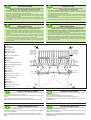
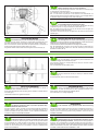
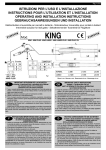
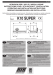
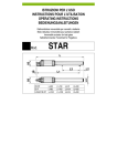
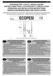
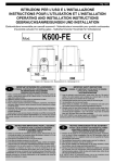
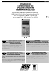
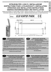
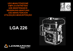
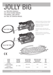
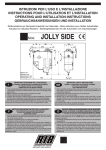
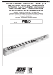
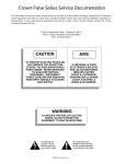
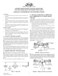
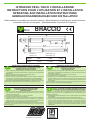
ISTRUZIONI PER L'USO E LÕINSTALLAZIONE INSTRUCTIONS POUR L'UTILISATION ET LÕINSTALLATION OPERATING AND INSTALLATION INSTRUCTIONS GEBRAUCHSANWEISUNGEN UND INSTALLATION Elettroriduttore irreversibile per cancelli a battente - MotorŽducteur irreversible pour portails ˆ battant Irreversible actuator for leaf gates - Selbsthemmender Torantrieb fŸr Flugeltore Mod. BRACCIO Misure in mm Mesures en mm Measurements in mm Abmessungen in mm NORMAL L=990 L1=860 L2=350 LUNGO L=1370 L1=1240 L2=700 IMPORTANTI ISTRUZIONI PER LA SICUREZZA IMPORTANT SAFETY INSTRUCTIONS I GB ATTENZIONE - ƒ IMPORTANTE PER LA SICUREZZA DELLE PERSONE CHE VENGANO SEGUITE TUTTE LE ISTRUZIONI CONSERVARE CON CURA QUESTE ISTRUZIONI 1¡ - Tenete i comandi dell'automatismo (pulsantiera, telecomando etc.) fuori dalla portata dei bambini. I comandi devono essere posti ad unÕaltezza minima di 1,5mt dal suolo e fuori dal raggio dÕazione delle parti mobili. 2¡ - Effettuare le operazioni di comando da punti ove l'automazione sia visibile. 3¡ - Utilizzare i telecomandi solo in vista dell'automazione. 4¡ - Avvertenze: Sulle altre misure di Protezione contro rischi attinenti l'installazione o l'utilizzazione del Prodotto vedi, a completamento di questo libretto di Istruzioni, le Avvertenze RIB allegate. Qualora queste non siano pervenute chiederne l'immediato invio all'Ufficio Commerciale RIB. LA DITTA RIB NON ACCETTA NESSUNA RESPONSABILITË per eventuali danni provocati dalla mancata osservanza nell'installazione delle norme di sicurezza e le leggi attualmente in vigore. WARNING - IT IS IMPORTANT FOR THE SAFETY OF PERSONS TO FOLLOW ALL INSTRUCTIONS SAVE THESE INSTRUCTIONS 1¡ - Keep the automatism control (push-button, remote control, etc) out of the reach of children. The control systems must be installed at a minimum hight of 1.5 mt from the groundsurface and not interfere with the mobile parts. 2¡ - Command pulses must be given from sites, where You can see the gate. 3¡ - Use transmitters only if You can see the gate. 4¡ - Warnings: when you have finished reading this instruction booklet, please refer to the RIB instructions attached for the other precautionary measures against risks connected with the installation or use of the product. If you have not received these, ask RIB Export Office to send them immediately. R.I.B. ACCEPTS IS NOT LIABLE for any damage caused by the not abiding ofthe safety regulations and laws at present in force not being observed during installation. WICHTIGE GEBRAUCHSANWEISUNGEN F†R DIE SICHERHEIT INSTRUCTIONS IMPORTANTES POUR LA SECURITE F D ACHTUNG - UM PERSONEN VOLLKOMMEND GARANTIEREN ZU KšNNEN IST ES WICHTIG DASS ALLE INSTALLLATIONSVORSCHRIFTEN BEOBACHTET WERDEN 1¡ - Bewahren Sie die GerŠte fŸr die automatische Steuerung (Drucktaster, Funksender, u.s.w.) an einem fŸr Kinder unzugŠnglichen Platz auf. Die Steuerungen mŸssen mindestens auf einer minimal Hšhe von 1,5 mt gestellt werden und sich ausserhalb der Raum der bewegenden Teile befinden. 2¡ - Die BetŠtigung der automatischen Steuerungs soll nur ausgefŸhrt werden wenn die automatische Anlage sichtbar ist. 3¡ - Die Funksender nur inn den FŠllen benŸtzen wenn die automatische Anlage sichtbar ist. 4¡ - Achtung: FŸr weitere Schutzma§nahmen im Rahmen der Installation und Anwendung der Produkte siehe die beiliegenden RlB-Sicherheitshinweise, die diese Gebrauchsanleitung ergŠnzen. Sollten Sie diese nicht erhalten haben, fšrdern Sie sie bitte sofort bei der RlB Exportabteilung an. DIE FIRMA R.I.B. HAFTET NICHT fŸr eventuelle SchŠden, die bei der Installation durch Nichtbeachtung der zur Zeit gŸltigen Sicherheitsvorschriften vertrommen entstanden sind. IL EST IMPORTANT POUR LA SECURITE DES PERSONNES DE SUIVRE ATTENTIVEMENT TOUTES INSTRUCTIONS GARDER MODE DÕEMPLOI 1¡ - Gardez les commandes de l'automatisme (boutons poussoirs, telecommande etc.) hors de la portŽe des enfants. Les commandes doivent •tre placŽes au minimum ˆ 1,5 m du sol, et hors de rayon dÕaction des pi•ces mobiles. 2¡ - Il faut donner les commandes d'un lieu, o• on peut voir l'automatisme. 3¡ - Il faut utiliser les Žmetteurs seulement si on voit le portail. 4¡ - Avertissements: Sur les autres mesures de Protection contre les risques relatifs a l'installation ou l'utilisation du Produit, voir, ˆ titre de complŽment de ce livret d'instructions, les Avertissements RIB ci-jointes. Dans le cas o• celles-ci ne vous seraient pas parvenues, en demander l'envoi immŽdiat au Bureau Commercial Etranger RIB (Ufficio Commerciale Estero RIB). L'ENTREPRISE R.I.B. N'ACCEPTE AUCUNE RESPONSABILITƒ pour des dommages Žventuels provoquŽs par le manque d'observation lors de l'installation des normes de sŽcuritŽ et lois actuellement en vigueur. ¨ automatismi per cancelli automatic entry systems I IMPORTANTI ISTRUZIONI DI SICUREZZA PER LÕINSTALLAZIONE GB ATTENZIONE - UNA SCORRETTA INSTALLAZIONE PUî PORTARE A DANNI RILEVANTI SEGUIRE TUTTE LE ISTRUZIONI PER UNA CORRETTA INSTALLAZIONE 1¡ - Questo libretto d'istruzioni • rivolto esclusivamente a del personale specializzato che sia a conoscenza dei criteri costruttivi e dei dispositivi di protezione contro gli infortuni per i cancelli, le porte e i portoni motorizzati (attenersi alle norme e alle leggi vigenti). 2¡ - Se non Ž previsto nella centralina elettrica, installare a monte della medesima un'interruttore di tipo magnetotermico (onnipolare con apertura minima dei contatti pari a 3mm) che riporti un marchio di conformitˆ alle normative internazionali. 3¡ - Per la sezione ed il tipo dei cavi la RIB consiglia di utilizzare un cavo di tipo NPI07VVF con sezione minima di 1,5mm2 e comunque di attenersi alla norma IEC 364 e alle norme di installazione vigenti nel proprio Paese. F IMPORTANT MODE DÕEMPLOI DE SECURITE POUR LÕINSTALLATION ❶ Elettroriduttore BRACCIO ❷ Antenna radio ❸ Lampeggiatore ❹ Selettore a chiave ❺ Fotocellule esterne ❻ Fotocellule interne WARNING -INCORRECT INSTALLATION CAN LEAD TO SEVERE INJURY FOLLOW ALL INSTALLATION INSTRUCTIONS 1¡ - This instruction booklet is exclusively dedicated to specialized staff who are aware of the construction criteria and of the accident prevention protection devices for motorized gates and doors (according to the current regulations and laws). 2¡ - To maintain electrical parts safely it is advisable to equip the installation with a differential thermal magnetic switch (onnipolar with a minimum opening of the contacts of 3mm) and must comply with the international rules. 3¡ - As for electric cable type and section RIB suggests cable type NPI07VVF with minimum section of 1,5mm2 and however respect IEC 364 rule and general national security regulations. D ATTENTION - UNE INSTALLATION INCORRECTE PEUT CAUSER DE GRANDS DOMMAGES SUIVRE TOUTES INSTRUCTIONS POUR UNE CORRECTE INSTALLATION 1¡ - Ce manuel d'instruction est adresse seulement au personnel specialisŽ qui a une connaissance des crit•res de construction et des dispositifs de protection contre les accidents en ce qui concerne les portails, les portes et les portes coch•res motorisees (suivre les normes et les lois en vigueur). 2¡ - A fin de proceder al'entretien des parties electriques, connecter ˆ l'installation un distonteur differentiel magneto thermique (qui disconnait toutes les branchements de la ligne avec ouverture min. des branchements de 3 mm ) et qui soit conforme aux normes internationales. 3¡ - Pour la section et le type des c‰bles ˆ installer nous vons conseillons di utiliser un cable NPI07VVF avec une section min de 1,5 mm 2 en respectant quand m•me la norme IEC 364 et les normes nationales d'installation. IMPORTANT SAFETY INSTRUCTION FOR INSTALLATION WICHTIGE SICHERHEITSVORSCHRIFTEN F†R DIE INSTALLATION ACHTUNG - EINE FALSCHE INSTALLATION KANN ZU BEDEUTENDE SHADEN F†HREN. F†R EINE KORREKTE ANLAGE ALLE GEBRAUCHSANWEISUNGEN FOLGEN 1¡ - Diese Montageanweisung kann ausschlie§lich von der Fachleuten gebraucht werden, die die Instandsetzung und die Schutzvorrichtungen zur Verhinderung von UnfŠllen bei motorisierten Toren kennen (nach die aktuellen Normen und Gesetze). 2¡ - FŸr die Wartung der elektrischen Teile ist es ratsam, zwischen der Anlage und dem Netzanschlu§ einen magnetisch-thermischen Differenzialschalter (mit der minimale …ffnung allen Kontakte von 3 mm) unterbricht die ein KonformitŠtzeichen aller internationaler Normen vortrŠgt. 3¡ - FŸr den Kabelguerschnitt und die Kabeltypen halten Sie sich an den Normen IEC 364 (minimale Kabelquerschnitt von der 1,5 mm2 mit der Bezeichnung NPI07VVF) und fŸr die Montage an die Normen des jeweiligen Landes. ❷ ❸ ❹ ❶ Electro-reducteur BRACCIO ❷ Antenne radio ❸ Signal electrique ❹ Selecteur ❺ Photocellules p/protection externe ❻ Photocellules p/protection interne ❶ BRACCIO operator ❷ Tuned aerial ❸ Flashing lamp ❹ Key selector ❺ Photoelectric cells (external) ❻ Photoelectric cells (internal) ❶ E-Torantrieb BRACCIO ❷ Antenne ❸ Blinkleuchte ❹ Schlusselschalter ❺ Photozelle Toraussenseitig ❻ Photozellen - innen ❻ ❺ ❶ ❻ ❶ ❺ ❹ ❻ ❻ Fig. 1 I CONTROLLO PRE-INSTALLAZIONE F CONTROLE PRE-INSTALLATION Il cancello a battente deve esserre solidamente fissato ai cardini delle colonne e non deve flettere durante il movimento. Prima d'installare il BRACCIO • meglio verificare tutti gli ingombri necessari per poterlo installare. Se il cancello si presenta come da Fig. 1 non occorrono modifiche. N.B. é obbligatorio uniformare le caratteristiche del cancello alle norme e leggi vigenti. Le pontai ˆ battant doit •tre solidement fixŽ aux cardans des colonnes et ne doit pas flechir pendant le mouvement. Avant d'installer le BRACCIO, il convient de verifier tous les encombrements necessaires pour proceder ˆ l'installation. Si le portail se presente comme indiquŽ Fig. 1, aucune modification n'est necessaire. N.B.: Il est obligatoire dÕadapter les caracteristiques du portail aux normes et lois en vigueur GB PRE-INSTALLATION CHECKS D PR†FUNG VON DER MONTAGE The leaf must be fixed firmily on the hinges to the pillars and must not be flexible during the movement. Before the installation of BRACCIO, verify all dimensions etc. There's no need for any modification, if the gate is like that shown in Fig. 1. ATTENTION: It is compulsory to conform the gate characteristics to the current regulations and laws. Das Flugeltor mu§ fest an der Angelpunkten der Trager fixiert sein und darf sich wahrend der Bewegung nicht biegen. Bevor BRACCIO montiert wird ist es besser alle Hindernisse, die bei der Montage auftreten konnen. festzustellen. Bei einem Tor wie in Abbildung 1 mussen keine Veranderungen vorgenommen werden. ACHTUNG: Mann ist verpflichtet die Eigenschaften des Gittertures zu die Gesetznormen in Einklang zu bringen CARATTERISTICHE TECNICHE CARACTERISTIQUES TECNIQUES TECHNICAL DATA TECHNISCHE EIGENSCHAFTEN NORMALE Lunghezza max.anta Longueur maxi du battant Max. leaf length Max. TorflŸgelweite m. Peso max cancello Poids maxi du portail Max. leaf weight Max. Torgewicht Kg Corsa max di traino Course maxi d'entrainement Max. travel Max. Hub cm 35 70 70 Tempo medio di apertura Temps moyen d'ouverture Average opening time Mittlere …ffnungszeit zirka s 17 20 35 Velocitˆ di traino Vitesse de traction Operating speed Laufgeschwindigkeit m/sec 0,013 Forza max di spinta Force maxi de poussŽe Thrust force Max. Schubkraft N 1500 Alimentazione e frequenza CEE Alimentation et frequence CEE EEC Power supply Stromspannung und frequenz CEE Potenza motore Puissance moteur Motor capacity Motorleistung W 150 230 Assorbimento Absorption Power absorbed Stromaufnahme A 0,85 1 Condensatore Condensateur Capacitor Kondensator mF 16 8 n¡ di cicli Nbre de cycles No. cycles Anzahl der Zyklen n¡ Alimentazione e frequenza Alimentation et frequence Power supply Stromspannung und frequenz Potenza motore Puissance moteur Motor capacity Motorleistung W 175 270 Assorbimento Absorption Power absorbed Stromaufnahme A 1 1,2 Condensatore Condensateur Capacitor Kondensator mF 16 8 n¡ di cicli Nbre de cycles No. cycles Anzahl der Zyklen n¡ Alimentazione e frequenza Alimentation et frequence Power supply Stromspannung und frequenz Potenza motore Puissance moteur Motor capacity Motorleistung W 165 250 Assorbimento Absorption Power absorbed Stromaufnahme A 1 1,1 Condensatore Condensateur Capacitor Kondensator mF n¡ di cicli Nbre de cycles No. cycles Anzahl der Zyklen n¡ Alimentazione e frequenza Alimentation et frequence Power supply Stromspannung und frequenz V Potenza motore Puissance moteur Motor capacity Motorleistung Assorbimento Absorption Power absorbed Stromaufnahme Condensatore Condensateur Capacitor Kondensator n¡ di cicli Nbre de cycles No. cycles Anzahl der Zyklen n¡ Tipo di olio Type d'huile Lubrification …lsorte Peso max Poids maximun Weight of electroreducer Motorgewicht Kg Rumorositˆ Bruit Noise GerŠusch db Volume Volume Volume Volumen m3 Grado di protezione Ind“ce de protection Protection Schutzart IP LUNGO LUNGO SPECIAL 3 4,5 2 300 450 0,0085 1000 220-230V~ 50Hz 50 - 20s/2s 14 - 35s/2s 220V~ 60Hz 45 - 20s/2s 10 - 35s/2s 240V~ 50Hz W 16 8 30 - 20s/2s 12 - 35s/2s 110~ Hz 60 190 210 A 2 1,9 mF 60 25 37 - 20s/2s 20 - 35s/2s IP MELLANA 100 17 15 <70 0,0171 0,0124 557 N¡ cicli = Numero di manovre complete minime garantite (apre+chiude), ammettendo un tempo massimo di funzionamento di 120 secondi con 2 secondi di pausa tra i movimenti (tempo massimo di funzionamento e tempo minimo di pausa tra le manovre settati su centralina RIB S111). No. cycles = minimum number of guaranteed complete movements (open+close), allowing 120 seconds maximum operating time with a two second pause between movements (maximum operating time and minimum pause time for the movements set on the RIB S111 control board). Il N¡ cicli aumenta quanto pi• breve • il tempo di funzionamento e lungo il tempo di pausa tra le manovre. The number of cycles increases as the operation time decreases, with respect to the pause time between movements. N¡ cicli = N¡ di manovre complete conteggiate fino al raggiungimento di una temperatura del motore di 125¡C (con motore a pieno carico con temperatura di avvio di 25¡C). No. cycles = number of complete movements carried out before the motor temperature reaches 125¡C (with motor at full load and starting temperature of 25¡C). I N¡ cicli = Non indica che il motore subito dopo aver eseguito queste manovre vada in termica. GB No. cycles = the motor shows no sign of overheating after completing these cycles. Nbre de cycles = Nbre minimum de manoeuvres compl•tes garanties (ouverture + fermeture), en admettant un temps maximum de fonctionnement de 120 secondes avec 2 secondes de pause entre les mouvements (temps maximum de fonctionnement et temps minimum de pause entre les mouvements programmŽs sur le coffret Žlectronique RIB S111). Anzahl der Zyklen = Mindestanzahl der garantierten kompletten Bewegungen (…ffnen + Schlie§en), wobei die max. Betriebszeit 120 Sekunden mit 2 Sekunden Pause zwischen den Bewegungen (auf der Steuertafel RIB S111 programmierte max. Betriebszeit und minimale Pause zwischen den Bewegungen). Plus le temps de fonctionnement est bref et plus le temps de pause entre les manoeuvres est long, plus le nombre de cycles augmente. Die Zyklenanzahl erhšht sich, wenn die Betriebszeit kŸrzer und die Pause zwischen den Bewegungen lŠnger wird. Nbre de cycles = Nbre de manoeuvres compl•tes comptŽes avant que le moteur nÕait atteint une tempŽrature de 125 ¡C (avec moteur ˆ pleine puissance et tempŽrature de dŽmarrage de 25 ¡C). Anzahl der Zyklen = Anzahl der kompletten Bewegungen bis der Motor eine Temperatur von 125¡C erreicht (bei voller Motorleistung mit einer Anfangstemperatur von 25¡C). Nbre de cycles = Ne signifie pas que le moteur se met en veille immŽdiatement apr•s lÕexŽcution de ces manoeuvres. Anzahl der Zyklen = Zeigt nicht an, da§ der Motor sofort nach diesen Bewegungen blockiert wird. F D I CARATTERISTICHE TECNICHE MOTORIDUTTORE F CARACTERISTIQUES TECHNIQUES MOTOREDUCTEUR I FISSAGGIO ATTACCHI MOTORE F FIXATION MOTEUR Braccio • un motoriduttore irreversibile utilizzato per movimentare cancelli a battente di lunghezza max di 2 m (Normal), 3 m (LUNGO), o 4,5 m (LUNGO SPECIAL). Braccio • stato concepito per funzionare senza finecorsa elettrici, ma solo meccanici. Quando • arrivato in battuta il motore funziona ancora per qualche secondo frizionando, fino a quando non interviene il timer di funzionamento. Braccio est un motorŽducteur irrŽversible, utilisŽ pour la commande de portails ˆ battants de longueur maximum de 2 m (Normal), 3 m (LONG), ou 4,5 m (LONG SPECIAL). Braccio a ŽtŽ con•u pour fonctionner sans fins de course Žlectriques, mais seulement mŽcaniques. Quand il arrive en butŽe le moteur fonctionne encore pendant quelques secondes en dŽbrayant, jusqu'ˆ ce qu'intervienne le temporisateur de fonctionnement. Se la colonna • in ferro le si pu˜ saldare direttamente l'attacco. Se la colonna • in cemento si utilizza la piastra come in Fig. 2 e la si fissa con quattro Fischer di ¯ 8 mm. Altro intervento possibile consiste nel murare l'attacco nella colonna saldandogli alla base una zanca come in Fig. 3. Proseguendo nell'installazione si deve saldare sull'anta l'attacco per la chiocciola di traino del cancello, osservando naturalmente le quote previste (Fig. 4, 5). Saldare lo zocchetto alla giusta altezza, montare il cavallotto con serratura e stringere la vite nella posizione che si crede pi• adatta (Fig. 4). Installare il BRACCIO provando pi• volte ad aprire e chiudere controllando che il profilo coprivite non sfreghi nel cancello in movimento, altrimenti riposizionare il cavallotto (Fig. 5). In caso si abbia il muro parallelo al cancello quando questo • aperto, si rende necessario praticare una nicchia per dare una sede al motoriduttore. Installando il BRACCIO • necessario rispettare alcune misure per avere un corretto movimento dell'anta (Fig. 6). Si la colonne est en fer, il est possible de sonder directement la fixation. Si la colonne est en ciment, proceder toujours avec une plaque comme indique Fig. 2, et la fixer avec quatre Fischer de ¯ 8 mm. Il est aussi possible de sceller la fixation dans la colonne en soudant une agrafe a sa base, voir Fig. 3. Ensuite poursuivre l'installation en soudant sur le vantail la fixation pour le dispositif d'entrainement du portail, en respectant les mesures prevues (Fig. 4, 5). Souder le socle ˆ la juste hauteur, monter le cavalier avec serrure et serrer la vis dans la position la plus appropriŽe (Fig. 4). Installer le BRACCIO en essayant plusieurs fois d'ouvrir et de fermer en controlant que le profile cache-vis ne frotte pas lorsque le portail est en mouvement, dans le cas contrarie, repositionner le cavalier (Fig. 5). En cas de mur parall•le au portail lorsque celui-ci est ouvert il est necessaire de pratiquer une niche pour loger le motoreducteur. Lors de l'installation du BRACCIO, il est necessaire de respecter certaines mesures afin d'obtenir un mouvement correct du vantail (Fig. 6). Fig. 2 Fig. 3 Fig. 4 GB GEARMOTOR TECHNICAL CHARACTERISTICS D TECHNISCHE DATEN GETRIEBEMOTOR GB MOTOR INSTALLATION D BEFESTIGUNG DER MOTORVERANKERUNG ÒBraccioÓ is an irreversible geared motor without electrical limitswitches, designed to move hinged gates with maximum length 2 m (NORMAL), 3 m (LONG) or 4.5 m (SPECIAL). ÒBraccioÓ has been designed to operate with mechanical limitswitches and not electrical ones. When the gate reaches its rest position, the motor continues to operate for a few seconds with the clutch engaged until it is interrupted by the operation timer. Braccio ist ein ausgestatteter selbsthemmender Getriebemotor zum Antrieb von FlŸgeltoren mit einer max. LŠnge von 2 m (Normal), 3 m (LANG) bzw. 4,5 m (SPEZIALL€NGE). Braccio ist fŸr einen Betrieb ohne elektrische Endschalter, aber mit mechanischen EndanschlŠgen ausgelegt. Nach Erreichen des Anschlags arbeitet der Antrieb noch einige Sekunden bis zum Ansprechen des Timers. If there is an iron pillar you can weld the anchorage directly. If there is a cement pillar, you can use the fixing plate as in Fig. 2 which is fastened with 4 Fischer-screws of ¯ 8 mm. There is also the possibility to cement the anchorage welding an anchor Fig. 3 with the base. Afterwards you must weld the actuator to the gate. Naturally you have to respect the measures predetermined Afterwards you must weld the actuator to the gate (Fig. 4, 5). Weld the base at the right height, assemble the emergency release mounting and thigten the screw in the right position (Fig. 4). Fix the BRACCIO and try several times to open and to close the gate, controlling that the screwcover does not touch the moving gate, otherwise you have to readjust the emergency release mounting (Fig. 5).In the case you have a wall parallel with the open gate, you must provide a niche in which to place to reducer. To obtain a correct movement of the leaf gate it is necessary to respect the measures (Fig. 6). Falls der Tortrager aus Eisen ist, kann man die Verankerung direkt anschwei§en. Bei einem TortrŠger aus Zement bedient man sich einer Platte wie in Abb. 2, die man mit 4 Fischer-DŸbel ¯ 8 mm anschraubt. Man kann die Verankerung auch in den TrŠger einmauern. Dazu schwei§t man am Sockel einem Haken an (wie in Abb. 3). Nacher wird auf den TorflŸgel der Anschlu§ fur die Fšrderschneke geschwei§t. Die vorgesehenen Ma§e sind naturlich zu beachten (Abb. 4, 5). Schwei§en Sie den Sockel in der richtigen Hohe, montieren Sie den Bugel mit dem Schlo§ und ziehen Sie die Schraube so an, wenn Sie ihnen in der richtigen Position scheint (Abb. 4). Befestigen Sie BRACCIO und versuchen Sie mehrere Male zu offnen und zu schlie§en, kontrolieren Sie dabei, da§ das Profil der Schraubenabdeckung das Tor in Bewegung nicht beruhrt. In diesem Fall, stellen Sie den Bugel neu ein (Abb. 5). Im Falle, es existiert eine Maurer, die parallel zum Tor im offenen Zustand lŠuft, ist es notwendig eine Wandvertiefung zu schaffen, um Platz fŸr den Motorantrieb zu haben. Um BRACCIO zu montieren, mu§en einige Ma§e beachtet werden, damit eine richtige Bewegung des Torflugels gegeben ist (Abb. 6). Fig. 5 MISURA ANTA MOTORE CONSIGLIATO MESURE PORTE MOTEUR CONSEILLƒ LEAF LENGHT MOTOR SUGGESTED TORFLUGELWEITE a A 0 Ö 1,5 m B C D 85 125 100 Normale 850 1,5 Ö 2 m GERATET ANTRIEB 100 150 130 100 150 170 Lungo 120 170 200 Lungo Special 85 150 90 Normale 95¡ 2Ö3m 1220 3 Ö 4,5 m 850 0Ö2m 1 2Ö3m 2 Lungo 115¡ 1220 3 Ö 4,5 m A 120 260 130 Lungo Special Fig. 6 I Qualora il pilastro fosse molto largo e non fosse possibile installare l'elettroriduttore rispettando la misura (D), • indispensabile creare una nicchia nel pilastro o spostare il cancello sullo spigolo. GB If the pillar is too large, and it is not possible to adjust the actuator respecting the measure (D), you must make a niche in the pillar or you have to move the gate to the edge of the pillar. F Si le pilier est tr•s large et n'est pas possible d'installer le motoreducteur en respectant la mesure (D), il faut realiser une niche dans le pilier ou deplacer le portail sur l'arete. D Falls der Torantrieb nicht mit dem richtigen Ma§ (D) montiert werden kann, da der Tortrager zu breit ist, mu§ man in der Saule eine Wandvertiefung schaffen oder das Tor an den Rand versetzen. F REGLAGE FINS DE COURSE MECANIQUES GB MECHANICAL LIMIT SWITCH CAM ADJUSTMENT D EINSTELLUNG DES MECHANISCHEN ENDSCHALTERS L'utilisation du moteur BRACCIO ne necessite pas de fixation de butŽe au sol ou autre car, a l'interieur, il est equipŽ de colliers d'arr•t reglables tant pour l'ouverture que pour la fermeture. Pour acceder aux colliers, il est necessaire d'oter le carter de protection vis en agissant selon les indications du schema, dans le sens de la fleche (Fig. 7). Pour obtenir l'ouverture desirŽe, il suffit de dŽplacer le collier (A) et de le bloquer ˆ la vis mere avec une clŽ allen n¡4. Pour obtenir la fermeture desirŽe, il est necessarie de deplacer le collier (B) en faisant attention que le motorŽducteur se decroche de la fixation portail sans effort. Using the actuator BRACCIO it isn't necessary to fix any stops on the ground or elsewhere, because in the inside it is fitted with a adjustable nut-stops, to limit the opening and closing the gate. To adjust the nuts you have to remove the screw-cover and you must turn it in the sense of the arrow shown as in the scheme (Fig. 7). To obtain the desired opening limit it's sufficient to adjust the nut (A) and to tighten it with a key n¡4. To obtain the desired closing limit you must adjust the nut (B), paying attention that the actuator can be released without any force from the gate using the emergency release. Fig.7 I REGOLAZIONE FINECORSA MECCANICI Usando il motore BRACCIO non • necessario fissare fermi a terra o altro perchŽ • dotato all'interno di ghiere di fermo registrabili sia per l'apertura che per la chiusura. Per accedere alle ghiere si deve sfilare il carter copri vite agendo come da schema nel senso della freccia (Fig. 7). Per ottenere l'apertura desiderata • sufficiente spostare la ghiera (A) e bloccarla alla vite madre con una chiave a brugola n¡4. Per ottenere la chiusura desiderata si dovrˆ spostare la ghiera (B) e fare attenzione che l'elettroriduttore si sganci senza sforzo dall'attacco cancello. Mit dem Motor BRACCIO ist es nicht notwendig, Endanschlage am Boden oder anderswo zu fixieren, weil dieser Motor im Inneren mit einstellbaren Anschlagsnutmuttern ausgestattet ist, die sowohl beim Offnen wie beim Schliessen reagieren. Um die Nutmuttern einzustellen mu§en Sie das Gehause der Schraubenabdeckung abnehmen und diese wie in der Abbildung im Sinne des Pfeils drehen (Abb. 7). Um die erwunschte Offnungsweite einzustellen genungt es, die Nutmuttern (A) zu verstellen und sie mit Hilfe eines Imbusschlu§els an der Mutterschraube festzuziehen. Um die erwunschte Schliesselweite einzustellen, mu§en Sie die Nutmuttern (B) verstellen. Beachten Sie dabei, da§ sich der Torantrieb muhelos vor der Torbefestigung abkuppelt. F REGLAGE DE L'EMBRAYAGE DE SECURITE GB SAFETY CLUTCH ADJUSTMENT Effectuer seulement apres avoir coupŽ l'alimentation. Pour accŽder au groupe d'embrayage, ˆ bain d'huile, il faut retirer le couvercle (B) et agir sur les bagues qui compriment le ressort. Pour augmenter la force, tourner dans le sens des aiguilles d'une montre. N.B. : Il ne faut donner au portail que la force nŽcessaire ˆ son actionnement, une personne doit donc •tre en mesure de l'arr•ter avec la main. Un fois le rŽglage effectuŽ, se rappeler de bloquer les deux bagues l'une contre l'autre (Fig. 8). To be undertaken after disconnecting power supply. To gain access to the oil-cooled clutch unit, remove cover (B) and tighten the spring compression ring nuts. Turn ring nuts clockwise to increase thrust force. N.B.: The geared motor's thrust force must only be sufficient to move the gate, thus making it possible to stop the gate manually. Take care to secure the two ring nuts one against the other once the clutch has been adjusted (Fig. 8). Fig. 8 I REGOLAZIONE FRIZIONE Da effettuare dopo aver tolto l'alimentazione elettrica al motore. Per accedere al gruppo frizione, a bagno d'olio, si deve togliere il coperchietto (B) e agire sulle ghiere che comprimono la molla. Per dare maggior forza, awitare in senso orario. N.B.: La forza da dare al cancello deve essere solo quella necessaria a movimentarlo e quindi una persona deve essere in grado di fermarlo con la mano. A regolazione awenuta ricordarsi di bloccare le due ghiere una contro l'altra (Fig. 8). D EINSTELLUNG DER RUTSCHKUPPLUNG F MANOEUVRE DE SECOURS GB EMERGENCY RELEASE D NOTENTRIEGELUNG Die Wartungsarbeit nur nach der Ausschliessung der Spannung auszufŸhren. FŸr einen freien Zugang zum Kupplungsaggregat im …lbad den Deckel (B) abnehmen und auf die Nutmuttern zur Federspannung einwirken. FŸr eine hšhere Antriebskraft sind die Muttern im Uhrzeigersinn anzuziehen. N.B.: Die Antriebskraft des Tors darf nur so hoch sein, da§ das Tor geschlossen wird, aber per Hand angehalten werden kann. Nach der Einstellung sind die beiden Nutmuttern zu sichern (Abb. 8). Avec le modele Braccio, pour actionner le portail manuellement il est necessaire de dŽgager les motorŽducteurs du portail. Par consequent, introduire la clŽ appropriŽe dans la serrure, la tourner et soulever Braccio vers le haut (Fig. 9). Ainsi, le motorŽducteur sera decrochŽ du portail. Using the model Braccio manually it is necessary to release the actuator from the gate (Fig. 9). Insert the special key and turn it than lift the STAR actuator. Fig. 9 I SBLOCCO DI EMERGENZA I MANUTENZIONE Nel modello Braccio per poter agire manualmente sul cancello • necessario svincolare i motoriduttori dal cancello. Inserire quindi l'apposita chiave nella serratura, girare la medesima e sollevare il Braccio verso l'alto (Fig. 9). L'elettroriduttore risulterˆ cos“ sganciato dal cancello. Da effettuare solamente da parte di personale specializzato dopo aver tolto l'alimentazione elettrica al motore. Ogni anno ingrassare i cardini, controllare la forza di spinta esercitata dal motoriduttore sull'anta e verificare il livello dell'olio. Ogni due anni • consigliabile sostituire l'olio e lubrificare la madrevite con del grasso siliconico. In caso di problemi nell'installazione consultare la "TABELLA DEI POSSIBILI PROBLEMI. F ENTRETIEN Effectuer soulement par personnel specialisŽ apr•s avoir coupŽ l'alimentation. Tous les ans, graisser les gonds, contr™ler la force de poussŽe exercŽe par le motorŽducteur sur le portail et vŽrifier le niveau d'huile. Tous les deux ans, il est conseillŽ de changer l'huile et de lubrifier la vis-m•re avec une graisse ˆ base de silicone. En cas de difficultes lors de l'installation, consulter le "TABLEAU DES DIFFICULTES POSSIBLES" Um das Tor des Modells Braccio manuell zu bedienen, mŸ§en Sie den Torantrieb vom Tor lšsen. Sie mŸ§en also den dafŸr vorgesehenen Schlu§el in das Schlo§ stecken, drehen und das Braccio hochheben (Abb. 9). Der Torantrieb ist so vom TorflŸgel ausgehangt. GB MAINTENANCE To be undertaken only by specialized staff after disconnecting power supply. Lubricate the hinges and check the oil level and thrust force generated by the actuator on the gate once a year. Change the oil and lubricate the nut screw with silicon grease every two years. If there are any problems during installation, consult the ÒLIST OF POSSIBLE PROBLEMSÓ. D WARTUNG Die Wartungsarbeit nur durch spezialiesierten Fachleuten nach der Ausschliessung der Spannung auszufŸhren. Einmal jŠhrlich sind die Angelzapfen zu schmieren, die vom Getriebemotor ausgeŸbte Antriebskraft sowie der …lstand zu ŸberprŸfen. Es wird empfohlen, alle zwei Jahre einen …lwechsel durchzufŸhren und die Schnecke mit Silikonfett zu schmieren. Sofern Installationsprobleme auftreten, ziehenSie die ÒTABELLE VON EVENTUELLEN PROBLEMENÓ zu Rate. I SICUREZZE ELETTRICHE F SECURITES ELECTRIQUES I TABELLA DEI POSSIBILI PROBLEMI Oltre alle sicurezze meccaniche giˆ citate • obbligatorio, nel caso in cui il cancello abbia una lunghezza d'anta maggiore di 1,80 m, l'utilizzo di due coppie di fotocellule in grado di interromperne il moto. Una coppia di fotocellule deve essere collocata a un'altezza variabile da 40 a 60 cm tra le colonne del cancello in posizione esterna al fabbricato. L'altra coppia di fotocellule deve essere collocata, alla stessa altezza della prima, alle estremitˆ delle ante del cancello quando questo • aperto. Il movimento del cancello deve essere sempre segnalato da un lampeggiatore collocato vicino al cancello. Si consiglia l'utilizzo delle centraline elettroniche di comando DE22FE-iec (per 2 motori monofasi) e DE22FE-iec/R2 (per 2 motori trifasi). Se viene utilizzato un solo motore • possibile richiedere il quadro DE2 (per 1 motore monofase) e S111 (per 1 motore trifase). Per i collegamenti ed i dati tecnici degli accessori attenersi ai relativi libretti. En plus des sŽcuritŽs mŽcaniques prŽcitŽes, lorsque les dimensions du vantail dŽpassent 1,80 m de largeur, il est obligatoire d'utiliser deux paires de cellules photo-Žlectriques en mesure d'interrompre le mouvement. Placez une paire de cellules photo-Žlectriques ˆ une hauteur variant entre 40 et 60 cm entre les colonnes du portail ˆl'extŽrieur. Placez l'autre paire de cellules photo-Žlectriques ˆ la m•me hauteur que la premi•re, aux extrŽmitŽs des vantaux du portail quand celui-ci est ouvert. Le mouvement du portail doit toujours •tre signalŽ par un feu clignotant placŽ ˆ proximitŽ du portail. Nous vous conseillons dÕutiliser des coffrets Žlectroniques DE22FE-iec (pour 2 moteurs monophasŽs) et DE22FE-iec / R2 (pour 2 moteurs triphasŽs). Si vous nÕutilisez quÕun seul moteur, il est possible de demander le coffret Žlectronique DE2 (pour 1 moteur monophasŽ) et S111 (pour 1 moteur triphasŽ). Problema BRACCIO non apre, ma chiude GB ELECTRICAL SAFETY DEVICES D ELEKTRISCHE SICHERHEITEN GB LIST OF POSSIBLE PROBLEMS In addition to compliance to all mechanical safety regulations, gates with leaf length exceeding 1.8 m must be fitted with two pairs of photocells capable of interrupting gate movement. The photocells must be installed at a height of 40 - 60 cm between the gate posts on the outside of the structure. The other two photocells must be installed at the same height as the previous ones on the ends of the gate leafs to form a barrier between the leafs when open. Gate movement must be indicated by a flashing unit placed near the gate. Use the DE22FE-iec (for two single-phase motors) and the DE22FE-iec/R2 (for two three-phase motors) electronic control units. If only one motor is used, the DE2 (for one single-phase motor) or the S111 (for one three-phase motor) control units are available. Neben den bereits angefŸhrten mechanischen Sicherheiten ist bei TorflŸgellŠngen Ÿber 1,80 m die Installation von 2 Lichtschrankenpaaren zur Unterbrechung des Vorschubs erforderlich. Ein Lichtschrankenpaar ist in einer Hšhe zwischen 40 und 60 cm auf den TorsŠulen au§erhalb des WerkgelŠndes zu installieren. Das andere Lichtschrankenpaar ist in der gleichen Hšhe an den FlŸgelenden bei offenem Tor anzubringen. Der FlŸgelvorschub ist stets durch einen im Torbereich installierte Warnblinker zu melden. Es wird die Verwendung der elektronischen SteuergerŠte DE22FE-iec (fŸr 2 einphasige Motoren) und DE22FE-iec/R2 (fŸr 2 dreiphasige Motoren) empfohlen. Falls nur ein Motor verwendet wird, kann die Steuertafel DE2 (fŸr 1 einphasigen Motor) und S111 (fŸr 1 dreiphasigen Motor) bestellt werden. Soluzione Invertire V con W Il motore non ha la forza di muovere Agire sulla frizione dando pi• forza di l'anta. spinta (senza esagerare) (Fig. 8). Problem BRACCIO does not open, but closes Solution Invert on the motor V instead W Il motore non funziona. Controllare l'alimentazione. The motor has not the force to move the Adjust the safety clutch as much as it is necessary to reset the gate in movement gate without forcing it (Fig. 8). Il motore dopo pochi secondi si ferma. Regolare il timer di funzionamento . The motor does not work Control the connections The motor stops after few seconds Adjust the operating timer on the control box F TABLEAU DES DIFFICULTES POSSIBLES Probleme D Probleme Solution BRACCIO n'ouvre pas, mais il ferme Inverser V avec W. BRACCIO n'a pas de force de traction. Operer sur l'embrayage autant qu'il faut afin de retablir le mouvement de la grille sans le forcer (Fig. 8). Le moteur ne fonctionne pas. Controler l'alimentation. Le moteur s'‰rrete aprŽs quelques Regler le temps de fonctionnement sur le secondes. coffret electronique. I N.B.:ƒ obbligatoria la messa a terra dell'impianto F N.B:La mise ˆ la terre de l'installation est obligatoire I dati descritti nel presente manuale sono puramente indicativi. La RIB si riserva di modificarli in qualsiasi momento. Realizzare lÕimpianto in ottemperanza alle norme ed alle leggi vigenti. Les donnees techniques decrites dans ce present manuel sont purement a titre indicatif. La RIB se reserve le droit de les modifier ˆ n'importe quel moment. Adapter les installation du parties electriques aux normes et lois en vigueur. TABELLE EVENTUELL AUFTRETENDER PROBLEME Lšsung BRACCIO šffnet nicht, sondern schlie§t nur. Invertieren Sie V und W. BRACCIO hŠlt keine Zugkraft. Betatigen Sie die Kupplung so lange bis das Tor sich wieder norrnal bewegt, ohne es dabei zu belasten (Abb. 8). Der Motor funktioniert nicht †berpnifen Sie die Stromversorgung. Der Motor hŠlt nach wenigen Sekunden an. Stellen Sie den Timer richtig ein. GB N.B.: The system absolutely must be earthed. The technical data given in this manual are only aproximate. RIB reserves the right to modify technical data at any time without previous notice. The installation must be installed according to the current regulations and laws. D Bitte beachten Sie: Das Erden der Anlage ist obligatorish Die in dem vorliegenden Handbuch angegebenen technischen Dater sind rein informativ. Firma RIB behalt sich das Rech vor, sie jederzeit zu Šndern. Die Installation mu§ nach die aktuellen Gesetznormen installiert werden. BA10004 BA10005 BA10009 CAL1046 CAL1048 CAL1049 CAL1050 CAL1053 CCA1370 CCA1371 CBCRAX725 CCU6203 CEL1073 CEL1378 CEL1379 CEL1381 CEL1382 CEL1385 CME1023 CME2007 CME5065 CME5093 CME6028 CME6029 CME6900 CME7019 CME8051 CME8052 Denominazione Particolare Attacco cancello completo Gruppo frizione completo Gruppo chiocciola di movimento Calottina Tappo con marchio Coperchio superiore Coperchio laterale Attacco cancello alluminio Piatto attacco colonna Attacco colonna Cuscinetto combinato RAX 725 Cuscinetto 6203 Pressacavo ottone nichelato 3/8 Condensatore 60µF 450V Condensatore 25µF 450V Condensatore 20µF 450V Condensatore 16µF 450V Condensatore 8µF 450V Alberino centrale Corona elicoidale Flagetta frizione conica Ghierafinecorsa Perno posteriore Tirante Grano per finecorsa meccanico Attacco cancello Profilo coprimotore Profilo coprivite normale CME8053 CME8076 CME8077 CME8078 CME9015 CMO1086 CMO1087 CMO1089 CMO1093 CMO1094 CMO1095 CPL1086 CPL1087 CPL1088 CPL1089 CTC1004 CTC1034 CTC1041 CTC1042 CTC1096 CTC1117 CTC1151 CTC1160 CVA1027 CVA1048 Denominazione Particolare Profilo coprivite lungo Carcasa centrale Chiocciola Supporto posteriore Vite madre lunga Mot. Normale e Lungo 230V / 50Hz Mot. Normale e Lungo 220V / 60Hz Mot. Normale e Lungo 110V / 60Hz Mot. Lungo Special 230V / 50Hz Mot. Lungo Special 110V / 60Hz Mot. Lungo Special 220V / 60Hz Ingranaggio conico con mozzo Ingranaggio conico Cuscinetto nylon Cuscinetto nylon Chiavetta 6X6X12 Guarnizione Molla a tazza 18,3X35.5X2 Molla a tazza 16.3X31.5X1.75 Paraolio 20X40X10 Seeger E15 Spina cilindrica 4X10 Spina elastica 5X30 Ghiera KM3 17 X 1 Serratura sblocco BRACCIO ® Dir.89/336/CEE Dir.73/23/CEE Codice Cod. AA 10001/11001/12001 - 960117 - Rev. 01 Codice 25014 CASTENEDOLO (BS)-ITALY Via Matteotti, 162 Telefono 030.2135811 Telefax 030.21358279 automatismi per cancelli automatic entry systems http://www.ribind.it - email: [email protected] La presente macchina non pu˜ funzionare in modo indipendente ed • destinata ad essere incorporata in un impianto costituito da ulteriori elementi. Rientra perci˜ nellÕArt. 4 paragrafo 2 della Direttiva 89/392/CEE (Macchine) e successive modifiche, per cui segnaliamo il divieto di messa in servizio prima che lÕimpianto sia stato dichiarato conforme alle disposizioni della Direttiva Il Presidente