1
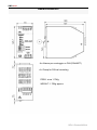
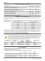
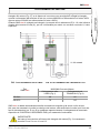
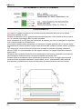
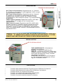
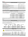
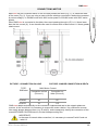
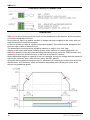
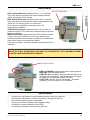
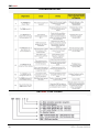
SMS-start
SOFT STARTER TRIFASE
3 PHASE SOFT STARTER
MANUALE D’USO
USER MANUAL
ITALIANO
ENGLISH
REV 0 PRINTED 09/2014
Printed 09/2014
SMS-start
DIMENSIONI/WEIGHT
A= Attacco per montaggio su DIN (DIN46277)
A= Clamp for DIN rail mounting
PESO: circa 1.75Kg
WEIGHT: 1.75Kg approx
REV 0 Printed 09/2014
SMS-start
IMPORTANTE
INTRODUZIONE
SMS-start è un avviatore per motori asincroni trifase, adatto per ridurre la corrente di avviamento.
Negli impianti di ascensore a sollevamento idraulico (tempo di avviamento 1 secondo), la corrente di avviamento si riduce a meno della metà della corrente di avviamento diretto, negli impianti
tradizionali a fune (tempo di accelerazione 3 secondi) si ottiene una corrente di avviamento di
circa 0,7 volte la corrente di avviamento diretto.
SMS-start prevede due taglie di dispositivi, di uguali caratteristiche meccaniche ma diverse
caratteristiche elettriche (vedi Cap. 3). Entrambe includono una funzione di Bypass interno per gli
SCR del soft starter durante la marcia.
AVVERTENZE IMPORTANTI PER LA SICUREZZA
Leggere attentamente questo manuale prima di procedere all’installazione o alla manutenzione.
Le avvertenze per la sicurezza non contemplano tutte le cause che provocano il malfunzionamento del dispositivo, ma danno evidenza delle cause più comuni.
I simboli elencati di seguito compaiono sul presente documento o sull’apparecchiatura per avvertire di potenziali pericoli e richiedono un’attenzione speciale.
QUESTO SIMBOLO INDICA DI PORRE
QUESTO SIMBOLO INDICA PERICOLO
PARTICOLARE ATTENZIONE
DI SCARICHE ELETTRICHE
Se il dispositivo è visibilmente danneggiato, se mancano componenti o se la taglia del dispositivo non è
adeguata a quella del motore, NON procedere all’installazione.
Quando il dispositivo è collegato alla linea è soggetto a tensioni pericolose.
L’installazione, il controllo e la manutenzione del dispositivo devono essere effettuate da personale autorizzato adeguatamente istruito, e devono essere eseguite solo quando è isolato dalla rete elettrica.
Un’installazione errata può causare il malfunzionamento dell’apparecchiatura, lesioni, o anche la morte.
Seguire scrupolosamente le norme di sicurezza vigenti.
Il dispositivo deve essere collegato a TERRA e i circuiti protetti adeguatamente, in conformità alle norme
vigenti.
Per garantire il corretto funzionamento del dispositivo e per non incorrere in rischi di incendio, utilizzare
cavi di sezione adeguata in funzione della corrente e della lunghezza del collegamento.
Evitare che qualsiasi tipo di oggetto esterno entri nel dispositivo, in quanto può portare al malfunzionamento dello stesso o a condizioni di pericolo, al momento della connessione alla rete elettrica.
Assicurarsi che ai morsetti di comando del dispositivo non siano presenti tensioni con potenziali riferiti alla
rete elettrica.
I conduttori di controllo e di potenza devono essere accuratamente isolati gli uni dagli altri.
Un eventuale gruppo di rifasamento statico deve essere connesso a monte del dispositivo (Terminali L1L2-L3) e mai a valle (Terminali U,V,W).
L’errata connessione può provocare condizioni di pericolo e/o la rottura del dispositivo.
Gli esempi e gli schemi contenuti in questo Manuale sono riportati a solo titolo dimostrativo.
Il contenuto del presente Manuale è soggetto a modifiche senza obbligo di preavviso.
In nessun caso verrà accettata la responsabilità per danni, indiretti o consequenziali, risultanti dall’utilizzo o
dall’applicazione del dispositivo.
REV 0 Printed 09/2014
01
ITALIANO
Prima di utilizzare il prodotto, leggere il presente manuale dell’utente.
Leggere con attenzione la presente sezione e attenersi con precisione alle istruzioni in essa
contenute. La garanzia non copre i danni derivanti dal mancato rispetto delle istruzioni in esso
contenute.
SMS-start
CARATTERISTICHE TECNICHE
Tipo SMS-start
SSV040
SSV070
Corrente nominale per carico leggero
Applicazione per ASCENSORI - Servizio INTERMITTENTE (*)
40A
70A
Corrente nominale per carico pesante
Applicazione INDUSTRIALE -Servizio CONTINUO
30A
45A
Massima corrente avviamento
120A
180A
Massima corrente istantanea
180A
270A
(*)Il servizio e’ da considerarsi intermittente se la motorizzazione avviene per un tempo inferiore o uguale a 60” ogni 120”.
Temperatura ambiente 0 ÷ 50°C Grado di protezione IP20
NUMERO DI AVVIAMENTI/ORA
SMS-start e’ progettato per poter eseguire un numero elevato di avviamenti/ora, anche in condizioni critiche.
Il numero massimo di avviamenti/ora dipende dalla durata dell’accelerazione, come riportato nella
tabella seguente:
Tempo di accelerazione
N° MAX Avviamenti/Ora
1 sec
75 avv./h
2 sec
40 avv./h
3 sec
25 avv./h
4 sec
18 avv./h
5 sec
15 avv./h
La tabella riporta il massimo numero di avviamenti/ora ottenibili con 50°C ambiente e correnti di
avviamento pari alla massima corrente sopportabile dal dispositivo. Con temperature inferiori e
correnti minori il numero di avviamenti/ora può essere maggiore.
FUSIBILI DI PROTEZIONE
Al fine di proteggere la parte di potenza (SCR) ed evitare condizioni di pericolo in caso
di corto circuito, si consiglia l’inserimento a monte della linea di alimentazione (L1L2-L3) di 3 fusibili con un I²t minore di quello massimo sopportato dall’SCR. I fusibili
indicati nella tabella garantiscono la protezione di Tipo 2.
Tipo SMS-start
I²t SCR @
45°C
Tipo
ITALWEBER
Codice
ITALWEBER
I²t Fusibile
SSV040
2120
CH14 50A aR
1461050
1800
SSV070
6810
CH22 80A aR
1462080
6600
COLLEGAMENTI
I collegamenti elettrici al dispositivo SMS-start devono essere eseguiti rispettando gli isolamenti e
le massime temperature ammesse dai cavi.
La Tabella riporta le sezioni minime in caso di utilizzo di cavo tipo N07V-K.
02
SSV040
SSV070
Terminali di potenza L1-L2-L3-U-V-W
10mm²
16mm²
Terminali di comando 1-2-3-4-5
1mm²
1mm²
REV 0 Printed 09/2014
SMS-start
COLLEGAMENTI AL MOTORE
FIG. 1-COLLEGAMENTO SULLA LINEA
Tipo
SMS-start
FIG. 2-COLLEGAMENTO NEL TRIANGOLO 6 FILI
MASSIMA Corrente Motore
Collegamento sulla
LINEA (Fig.1)
Collegamento nel
TRIANGOLO (Fig.2)
SSV040
40
65
SSV070
70
115
SMS-start si adatta automaticamente alla connessione eseguita ed al senso ciclico di rete.
Nel caso sia necessario invertire la rotazione del motore, sarà sufficiente invertire tra di loro due
fasi di alimentazione (es. R con S) e modificare opportunamente il collegamento all’eventuale
dispositivo di CONTROLLO SEQUENZA FASI, per mantenerlo funzionante.
IMPORTANTE!
Nel caso di connessione all’interno del triangolo del motore(Fig. 2) è necessario
invertire R con S e non L1 con L2!
REV 0 Printed 09/2014
03
ITALIANO
SMS-start può essere collegato sia sulla linea che alimenta il motore (Fig. 1), sia all’interno del
triangolo del motore (Fig. 2), se si dispone di un motore con avvolgimenti collegati a triangolo
quando è alimentato alla tensione di rete (es. motore 400/690 con alimentazione di rete a 400V
oppure motore 230/400 con alimentazione di rete a 230V).
Quando SMS-start è collegato nel triangolo, la corrente che lo attraversa (IF) è 1.6 volte inferiore
rispetto alla corrente di linea (IL), per cui è utilizzabile per motori con corrente nominale 1,6 volte
superiore.
SMS-start
COLLEGAMENTO CIRCUITI DI COMANDO
FUNZIONAMENTO
SMS-start e’ in grado di limitare sia la corrente di spunto assorbita dalla rete che la coppia
meccanica trasferita al carico.
Durante l’avviamento si ha un graduale aumento della tensione e della coppia fornita al motore,
con un costante monitoraggio della corrente assorbita.
A fine avviamento si ha il by-pass dei componenti di potenza, per ridurre la dissipazione e garantire un numero elevato di avviamenti/ora.
La funzione di decelerazione garantisce una riduzione di coppia graduale, per un arresto “dolce”.
L’avviamento del motore avviene a seguito della chiusura del contatto di marcia esterno (morsetti
1-2).
SMS-start avvia il motore fornendo inizialmente la coppia di partenza impostata mediante il
trimmer TORQ, e incrementandola fino alla coppia massima, nel tempo impostato mediante il
trimmer ACC.
All’apertura del comando di marcia inizia la decelerazione del motore, portando la tensione dal
valore massimo al valore minimo, nel tempo impostato dal trimmer DEC.
Durante la fase di avviamento viene monitorata la corrente di uscita. Al raggiungimento della
corrente di limite impostata mediante il trimmer IMAX, si ha il ”rallentamento” della rampa di
accelerazione, permettendo al motore di acquistare giri senza assorbire ulteriore corrente.
04
REV 0 Printed 09/2014
SMS-start
REGOLAZIONI
TRIMMER DI REGOLAZIONE
ITALIANO
ACC Tempo di accelerazione: Regolazione da 1 a 7 secondi.
E’ il tempo in cui la tensione di uscita raggiunge il 100%, a seguito di un comando di marcia.
DEC Tempo di decelerazione: Regolazione da 0 a 7 secondi.
E’ il tempo in cui la tensione di uscita passa dal 100% a 0,
all’apertura del comando di marcia. Se il trimmer è ruotato
completamente in senso antiorario (tempo = 0), la decelerazione
è disabilitata.
TORQ Coppia di partenza: Regolazione da10% a 25% della
coppia massima. E’ la coppia con cui il motore inizia
l’accelerazione.
IMAX Limite di corrente: Regolazione da 50% a 300% della
corrente nominale. E’ il massimo valore di corrente che si può
avere durante l’accelerazione. Al raggiungimento del valore
impostato si blocca la rampa di accelerazione, allungandone il
tempo. Se il tempo supera 7 secondi, il funzionamento si blocca
segnalando FAULT.
I TRIMMER SONO DOTATI DI PERNI PER FACILITARE LA REGOLAZIONE, SENZA USO
DI ATTREZZI. AL TERMINE DELLA MESSA IN MARCIA DEL DISPOSITIVO, E’ POSSIBILE RIMUOVERLI PER EVITARE SUCCESSIVE E INOPPORTUNE MODIFICHE.
SEGNALAZIONI
LED DI SEGNALAZIONE
PWR LAMPEGGIANTE = Alimentazione
scheda Logica presente.
RUN ON = Comando di MARCIA attivo.
END ON = Avviamento concluso, rimane attivo
durante la marcia e si spegne 0,5 secondi dopo
la fine della decelerazione: chiuso il contatto
3-4 e aperto il contatto 4-5.
FAULT ON= Stato di Blocco o di Fault generico. Per ripristinare il funzionamento, occorre
togliere il comando di marcia.
PROTEZIONI
•
•
•
•
•
•
Controllo della presenza delle fasi d’ingresso prima di effettuare l’avviamento.
Controllo della presenza del motore prima di effettuare l’avviamento.
Controllo termico sui componenti di potenza.
Controllo sul corretto funzionamento dei relè di bypass.
Controllo sul corretto funzionamento degli SCR.
Controllo di corrente massima durante l’avviamento.
REV 0 Printed 09/2014
05
SMS-start
RISOLUZIONE PROBLEMI
FORMATO CODICE SMS-start
06
REV 0 Printed 09/2014
SMS-start
NOTICE
INTRODUCTION
SMS-start is a three-phase asynchronous motor starter, designed to reduce starting current.
In hydraulic lift systems (1-second starting time), the starting current is reduced to less than half
of the direct starting current. In traditional rope lift systems (3-second acceleration time), a starting
current of approximately 0.7 times the direct starting current can be obtained.
SMS-start has two sizes with the same mechanical outfit but different electrical properties (see
Chapter 3). Both include an internal Bypass function for the soft starter SCRs during runtime.
IMPORTANT SAFETY WARNINGS ANT
Please read this manual carefully before proceeding with installation or maintenance.
The safety warnings do not cover all causes of device failure, but do identify the most common
causes.
The following symbols appear in this document or on the equipment to warn of potential hazards,
and they require special attention.
YOU MUST PAY PARTICULAR
RISK OF ELECTRIC SHOCK
ATTENTION
If the device is visibly damaged or missing components, or if the size of the device is not suitable for
the motor, DO NOT proceed with installation.
When the device is connected to the mains it is subject to hazardous voltages.
Installation, inspection and maintenance of the device must be performed by authorised and appropriately trained personnel, and should be performed only when it is disconnected from the electric
network.
Incorrect installation can cause equipment malfunction, injury or even death. Carefully follow the
safety regulations in force.
The device must be connected to GROUND and the circuits adequately protected, in accordance
with current standards.
To ensure correct device operation and in order to avoid the risk of fire, use cables with a suitable
cross section, depending on the current and the length of the connection.
Ensure that no type of external object enters the device, as it can lead to failure of the product or
hazardous conditions, when connecting to the electric network.
Make sure that there is no voltage on the device control terminals which could link to the electric
network.
The control and power conductors must be correctly isolated from each other.
Any static power factor correction unit must be connected upstream of the device (Terminals L1L2-L3) and never downstream (Terminals U, V, W).
Incorrect connection may cause hazardous conditions and/or device breakage.
The examples and diagrams in this manual are included solely for demonstration purposes.
The content of this manual is subject to change without notice.
In no event shall liability be accepted for damage, indirect or consequential, resulting from the use
or application of the device.
REV 0 Printed 09/2014
07
ENGLISH
Please read the manual before using and installing the device.
Read carefully the following paragraphs and pay attention to the instructions. Our warranty does
not cover any damage resulting from failure to follow instructions contained therein.
SMS-start
TECNICAL FEATURES
Type of SMS-start
SSV040
SSV070
Rated current for light load
Application for LIFTS - INTERMITTENT duty (*)
40A
70A
Rated current for heavy load
INDUSTRIAL application - CONTINUOUS duty
30A
45A
Maximum starting current
120A
180A
Maximum instantaneous current
180A
270A
(*)Duty is considered intermittent where the motor drive starts for a duration below or equal to 60” each 120”.Ambient temperature
0 ÷ 50°C . Degree of protection IP20
NUMBER OF STARTS/HOUR
SMS-start is designed to be able to carry out an increased number of starts per hour, even in
critical conditions.The maximum number of starts per hour depends on the acceleration duration,
as shown in the Table below:
Acceleration time
MAX No. Starts/Hour
1 sec
75 starts/h
2 sec
40 starts/h
3 sec
25 starts/h
4 sec
18 starts/h
5 sec
15 starts/h
The Table shows the maximum number of starts per hour which can be obtained at an ambient
temperature of 50°C and at starting currents equal to the maximum current supported by the
device.
PROTECTION FUSES
In order to protect the power component (SCR) and to avoid dangerous conditions in the event of
a short circuit, you are advised to install, upstream of the power line (L1-L2-L3), 3 fuses with an
I²t the the one is supported by the SCR.
The fuses shown in the Table ensure Type 2 protection.
Type of SMSstart
I²t SCR @
45°C
Type
ITALWEBER
Code
ITALWEBER
I²t Fuse
SSV040
2120
CH14 50A aR
1461050
1800
SSV070
6810
CH22 80A aR
1462080
6600
CONNECTIONS
The electrical connections to the SMS-start device must be carried out in accordance
with the isolations and maximum temperatures allowed by the cables.
The Table shows the minimum cross sections, where N07V-K type cables are used.
SSV040
SSV070
Power terminals L1-L2-L3-U-V-W
10mm²
16mm²
Command terminals 1-2-3-4-5
1mm²
1mm²
08
REV 0 Printed 09/2014
SMS-start
CONNECTIONS MOTOR
PICTURE. 1-CONNECTION ON LINE
TYPESMS-start
PICTURE. 2-INSIDE CONNECTION IN DELTA
MAX Motor Current
Connection on line
(Picture 1)
Connection on
delta (Picture 2)
SSV040
40
65
SSV070
70
115
SMS-start adapts automatically to the connection implemented and to the network phase sequence. In the event that it is necessary to reverse the motor rotation, it is sufficient to reverse
two supply phases between them (e.g. R with S), and consequently modify the connection of the
eventual PHASE CONTROL device, so that it keeps working fine.
IMPORTANT!
In the case of internal delta connection, it is necessary to reverse R with S and not
1 with L2!
REV 0 Printed 09/2014
09
ENGLISH
SMS-start can be connected either on the line that powers the motor (Fig. 1), or inside the delta
of the motor (Fig. 2), if you are using a motor with the windings connected in delta when powered
by mains voltage (i.e. 400/690 motor with 400V mains power or 230/400 motor with 230V mains
power).
When SMS-start is connected to the delta, the current passing through it (IF) is 1.6 times lower
than the line current (IL). It can therefore be used for motors with a rated current 1.6 times greater
rated current.
SMS-start
CONTROL CIRCUITS CONNECTION
OPERATION
SMS-start is able of limiting both the inrush current absorbed from the network, and the mechanical torque transferred to the load.
During start-up, there is a gradual increase in voltage and torque supplied to the motor, with constant monitoring of current consumption.
At the end of start-up, there is a power components bypass. This reduces power dissipation and
ensure a high number of starts per hour.
The deceleration function ensures a gradual reduction in torque, for a “soft” stop.
Starting of the motor takes place following closure of the external run contact (terminals 1-2).
SMS-start starts the motor by initially providing the starting torque set by the TORQ trimmer, and
increasing it up to the maximum torque, in the time set by the ACC trimmer.
Motor deceleration begins on opening of the run command, moving the voltage from the maximum
value to the minimum value, within the time set by the DEC trimmer.
During the starting phase the output current is monitored. On reaching the current limit set by the
IMAX trimmer, the “slowdown” of the acceleration ramp takes place, allowing the motor to rev
without using additional power.
10
REV 0 Printed 09/2014
SMS-start
ADJUSTMENT
ENGLISH
ADJUST TRIMMER
ACC Acceleration time:Adjustment from 1 to 7 seconds.
This is the time during which the output voltage reaches
100%, following a run command.
DEC Deceleration time: Adjustment from 0 to 7 seconds.
.
This
is the time during which the output voltage passes from
100% to 0, on opening of the run command.
If the trimmer is turned fully clockwise (time = 0),
deceleration is disabled.
TORQ Starting torque: Adjustment from 10% to 25% of
maximum torque. This is the torque with which the motor will
begin acceleration.
IMAX Current limit: Adjustment from 50% to 300% of rated
current.This is the maximum current value admit during
acceleration.When the set value is reached, the acceleration
ramp locks, thereby increasing its duration.
If the time exceeds 7 seconds, operation locks and FAULT is
indicated.
THE TRIMMERS ARE EQUIPPED WITH PINS IN ORDER TO FACILITATE ADJUSTMENT, WITHOUT
THE USE OF TOOLS. AT THE END OF THE START-UP OF THE DEVICE, YOU CAN REMOVE THEM
TO AVOID LATER INAPPROPIATE CHANGES.
INDICATORS
LED INDICATORS
PWR FLASHING = Logic board power supply present.
RUN ON= RUN command active.
END ON= Start complete, remains active during the run
and goes off 0.5 seconds after deceleration is complete: contact 3-4 closed and contact 4-5 open.
FAULT ON= Generic Lock or Fault state. To restore
operation, you must stop the run command.
SAFEGUARDS
•
•
•
•
•
•
Checking for the presence of input phases before carrying out start-up.
Checking for the presence of the motor before carrying out start-up.
Heat checking of the power components.
Checking of correct operation of the bypass relays.
Checking of correct operation of the SCRs.
Checking the maximum current during start-up.
REV 0 Printed 09/2014
11
SMS-start
TROUBLESHOOTING
SMS-start CODE FORMAT
12
REV 0 Printed 09/2014
REV 0 Printed 09/2014
13
SMS Sistemi e Microsistemi Srl (SASSI HOLDING Group)
Via Guido Rossa, 46/48/50 Loc. Crespellano, 40053 Valsamoggia (Bologna), Italy
Tel. +39 051/969 037 Fax +39 051/969 303
[email protected]
www.sms-lift.com