1
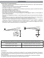
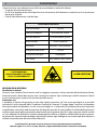
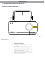
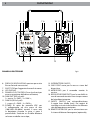
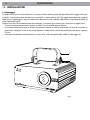
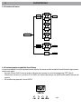
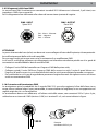
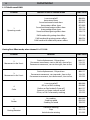
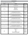
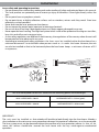
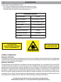
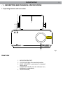
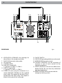
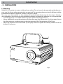
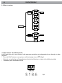
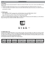
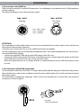
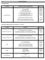
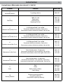
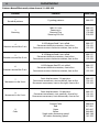
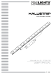
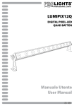
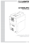
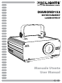
DIAMOND152
ENTERTAINMENT
LASER EFFECT
Manuale Utente
User Manual
I
GB
REV.002-10/10
DIAMOND152
3
INTRODUZIONE
Vi ringraziamo per aver scelto un prodotto PROLIGHTS.
DIAMOND152 è un proiettore laser realizzato con qualità
costruttiva e soluzioni tecniche in grado di unire performance
di spessore e ampia flessibilità nel controllo.
INDICE
Sicurezza
Avvertenze generali
Attenzioni e precauzioni per l’installazione
Sicurezza laser e istruzioni operative
Informazioni generali
4
4
5
6
1 Descrizione e specifiche tecniche
1. 1 Elementi di comando e collegamenti
1. 2 Descrizione
1. 3 Specifiche tecniche
7
9
9
2 Installazione
2. 1 Montaggio
10
3 Funzioni e impostazioni
3. 1 Funzionamento
3. 2 Impostazione base
3. 3 Struttura del menu
3. 4 Funzionamento in modalità Stand Alone
3. 5 Modalità Slave
3. 6 Collegamento
3. 7 Modalità DMX
3. 8 Indirizzamento DMX
3. 9 Collegamenti della linea DMX
3. 10 Costruzione del terminatore DMX
3. 11 Tabella canali DMX
11
11
12
12
13
14
14
14
15
15
16
4 Manutenzione
4. 1 Pulizia sistema ottico e manutenzione
19
Certificato di garanzia
CONTENUTO DELL’IMBALLO:
• DIAMOND152
• Cavo di alimentazione con spina
• Chiave (per safety switch) (2 p.zi)
• Connettore 2 poli per remote interlock
• Staffa di fissaggio
• Manuale utente
Music & Lights S.r.l. si riserva ogni diritto di elaborazione in qualsiasi forma delle presenti istruzioni per l’uso.
La riproduzione - anche parziale - per propri scopi commerciali è vietata.
Tutte le specifiche possono essere variate senza alcuna notifica.
DIAMOND152
4
ATTENZIONE! Prima di effettuare qualsiasi operazione con l’unità, leggere con attenzione
questo manuale e conservarlo accuratamente per riferimenti futuri. Contiene informazioni
importanti riguardo l’installazione, l’uso e la manutenzione dell’unità.
SICUREZZA
Avvertenze generali
• I prodotti a cui questo manuale si riferisce sono conformi alle Direttive della Comunità Europea e pertanto
recano la sigla .
• Il dispositivo funziona con pericolosa tensione di rete 230V~. Non intervenire mai al suo interno al di
fuori delle operazioni descritte nel presente manuale; esiste il pericolo di una scarica elettrica.
• È obbligatorio effettuare il collegamento ad un impianto di alimentazione dotato di un’efficiente messa a
terra (apparecchio di Classe I secondo norma EN 60598-1). Si raccomanda, inoltre, di proteggere le linee
di alimentazione delle unità dai contatti indiretti e/o cortocircuiti verso massa tramite l’uso di interruttori
differenziali opportunamente dimensionati.
• Le operazioni di collegamento alla rete di distribuzione dell’energia elettrica devono essere effettuate
da un installatore elettrico qualificato. Verificare che frequenza e tensione della rete corrispondono alla
frequenza ed alla tensione per cui l’unità è predisposta, indicate sulla targhetta dei dati elettrici.
• L’unità non per uso domestico solo per uso professionale.
• Il dispositivo è previsto solo per l’uso interno; evitare l’impiego in:
- luoghi soggetti ad elevata umidità dell’aria;
- luoghi a temperatura superiore ai 40°C o inferiori a 10°C.
• Evitare che nell’unità penetrino liquidi infiammabili, acqua o oggetti metallici.
• Non smontare e non apportare modifiche all’unità.
• Tutti gli interventi devono essere sempre e solo effettuati da personale tecnico qualificato. Rivolgersi al
più vicino centro di assistenza tecnica autorizzato.
• Se si desidera eliminare il dispositivo definitivamente, consegnarlo
per lo smaltimento ad un’istituzione locale per il riciclaggio.
Attenzioni e precauzioni per l’installazione
• Se il dispositivo dovesse trovarsi ad operare in condizioni differenti da quelle descritte nel presente manuale, potrebbero verificarsi dai danni; in tal caso la garanzia verrebbe a decadere. Inoltre, ogni altra
operazione potrebbe provocare cortocircuiti, incendi, scosse elettriche, rotture etc.
• Prima di iniziare qualsiasi operazione di manutenzione o pulizia sull’unità togliere la tensione dalla rete
di alimentazione.
• Ogni persona coinvolta con l’installazione e la manutenzione di questo dispositivo deve essere qualificata e seguire le istruzioni di questo manuale.
• Nell’eseguire qualsiasi intervento attenersi scrupolosamente a tutte le normative (in materia di sicurezza)
vigenti nel paese di utilizzo.
• È assolutamente necessario fissare l’unità per mezzo di una fune di sicurezza.
• La distanza minima tra il proiettore e le pareti circostanti deve essere superiore a 50cm e non devono
essere ostruite, in nessun caso, le aperture d’aerazione.
• Mantenere materiali infiammabili ad una distanza di sicurezza dall’unità.
• Assicurarsi che l’interruttore POWER è impostato su posizione di OFF prima di collegare il dispositivo alla
rete elettrica.
• Non accendere il dispositivo e spegnerlo dopo brevi intervalli in quanto ciò ridurrebbe la vita del diodo
laser.
• Non guardare direttamente il fascio luminoso. Tenere presente che i veloci cambi di luce possono provocare attacchi d’epilessia presso persone fotosensibili o epilettiche.
DIAMOND152
5
Sicurezza laser e istruzioni operative
• Non utilizzare il proiettore laser senza lettura e comprensione sulla sicurezza laser e sulle istruzioni operative
contenute in questo manuale.
• Il raggio laser può causare danni permanenti agli occhi ed alla pelle.
• Non dirigere il raggio laser su persone o animali.
• Non dirigere il raggio laser su superfici altamente riflettenti come finestre, specchi e metalli lucidi. Anche la
riflessione del laser può essere pericolosa.
• Non guardare mai l’apertura laser o i raggi laser.
• Non sottoporre l’uscita ottica (apertura), ai prodotti chimici di pulizia.
• Non utilizzare il proiettore laser se il corpo di alloggiamento è danneggiato o aperto, o se l’ottica appare in
qualche modo danneggiata.
• Non aprire mai l’alloggiamento del laser. I livelli di potenza del laser possono provocare lesioni alla pelle e
agli occhi.
• In alcuni Stati occorre sottostare a regole specifiche per l’impiego di apparecchiature laser. Si prega di chiedere informazioni specifiche, presso le autorità competenti, prima di adoperare il laser.
• Secondo le norme internazionali di sicurezza, il proiettore laser deve essere installato in modo che
il raggio laser presenta una distanza minima di 3 m dal pavimento se, sotto il raggio, si trattengono
delle persone. Tuttavia, il dispositivo può essere installato anche in modo che il raggio laser, in senso
orizzontale, sia ad una distanza minima di 2,5 m dalle persone.
Il presente laser, DIAMOND152, è attribuito alla classe 3B e presenta le seguenti caratteristiche:
POTENZA MAX DEL LASER = 50mW
LUNGHEZZA D’ONDA DEL LASER = 532nm (verde)
POTENZA MAX DEL LASER = 100mW
LUNGHEZZA D’ONDA DEL LASER = 650nm (rosso)
IMPORTANTE!
L’unità deve essere installata in modo tale da escludere che si possa guardare direttamente nel raggio laser. Anche una breve esposizione può provocare dei danni permanenti agli organi visivi. Si devono evitare
riflessi involontari.
Il funzionamento di un laser di classe 3B è consentito solo se controllato da un operatore qualificato.
Per impedire l’utilizzo non autorizzato servirsi dell’interruttore a chiave.
DIAMOND152
6
I dispositivi laser con radiazioni accessibili recano etichette in modo da indicare:
-- il segnale d’avvertimento laser;
-- la classe di appartenenza del dispositivo laser unitamente all’indicazione cautelativa e di avvertimento
pertinente, nonché
-- i dati di identificazione e i dati del tipo.
LASER EMISSION DATA
Laser Classification
Class 3B
Green Laser Medium
DPSS Nd:YVO4, 532nm
Red Laser Medium
LD GaAlAs 650nm, typical
Beam Diameter
<5mm at aperture
Pulse Data
All pulses < 4Hz (>0.25sec)
Divergence (each beam)
<2 mrad
Divergence (total light)
<160 degrees
Laser Power
Red<100mW, Green<50mW
LASER RADIATION
AVOID EXPOSURE TO THE BEAM
CLASS 3B LASER PRODUCT
LASER APERTURE
LASER RADIATION
INFORMAZIONI GENERALI
Spedizioni e reclami
Le merci sono vendute “franco nostra sede” e viaggiano sempre a rischio e pericolo del distributore/cliente.
Eventuali avarie e danni dovranno essere contestati al vettore. Ogni reclamo per imballi manomessi dovrà
essere inoltrato entro 8 giorni dal ricevimento della merce.
Garanzie e resi
Il prodotto è coperto da garanzia in base alle vigenti normative. Sul sito www.musiclights.it è possibile
consultare il testo integrale delle “Condizioni Generali di Garanzia”. Si prega, dopo l’acquisto, di procedere
alla registrazione del prodotto sul sito www.musiclights.it. In alternativa il prodotto può essere registrato
compilando e inviando il modulo riportato alla fine del manuale. A tutti gli effetti la validità della garanzia è
avallata unicamente dalla presentazione del certificato di garanzia. Music & Lights constata tramite verifica
sui resi la difettosità dichiarata, correlata all’appropriato utilizzo, e l’effettiva validità della garanzia; provvede quindi alla riparazione dei prodotti, declinando tuttavia ogni obbligo di risarcimento per danni diretti o
indiretti eventualmente derivanti dalla difettosità.
Le informazioni riportate in questo manuale sono state attentamente controllate.
Music & Lights S.r.l. non si assume, tuttavia, responsabilità derivanti da eventuali inesattezze.
DIAMOND152
7
- 1 - DESCRIZIONE E SPECIFICHE TECNICHE
1.1 Elementi di comando e collegamenti
2
1
43
Power
Music
LASER
APERTURE
152
5
VISTA FRONTALE
1. Staffa di montaggio.
2. Manopola di fissaggio per la staffa di
montaggio.
3. INDICATORE DEL SEGNALE MUSICALE: il LED
blu si accende se il microfono (15) rileva un
segnale musicale di volume sufficiente per
comandare il raggio laser.
4. Indicatore di funzionamento: quando il
LED rosso è acceso, il dispositivo è in funzione.
5. APERTURA RAGGIO LASER.
Fig.1
DIAMOND152
8
9
7 6
8
10
11
PANNELLO POSTERIORE
6. PRESA DI VENTILAZIONE: apertura per uscita
flusso d’aria da non ostruire.
7. SAFETY EYE per l’aggancio al cavo di sicurezza.
8. Led display.
9. PANNELLO DI CONTROLLO con 4 pulsanti per
accesso e gestione delle diverse funzioni;
10. DMX OUT (XLR a 3 poli):
1= massa, 2 = DMX -, 3 = DMX +;
11. DMX IN (XLR a 3 poli):
1 = massa, 2 = DMX -, 3 = DMX +;
12. POWER IN spina da pannello VDE per
il collegamento ad una presa di rete
(100-240V~/50-60Hz) tramite il cavo rete
in dotazione. Accanto la spina si trova il
portafusibile. Sostituire un fusibile difettoso
solo con uno dello stesso tipo;
18 17
12
16 15
13 14
Fig.2
13. INTERRUTTORE ON/OFF;
14. GND POINT usato per la messa a terra del
dispositivo;
15. MICROFONO per il comando tramite la
musica;
16. REGOLATORE SENSITIVITY per la sensibilità in
caso di comando tramite la musica per mezzo
del microfono integrato;
17. SAFETY SWITCH per attivare/disattivare
il raggio laser (diodo laser). Per ragioni di
sicurezza assicurarsi che la chiave sia utilizzata
solo dall’operatore autorizzato;
18. REMOTE INTERLOCK per la connessione con
il sistema di blocco d’emergenza (opzionale);
DIAMOND152
9
1.2 Descrizione
Prestazioni ed evoluzione tecnologica sono tra le prerogative nella progettazione e nello sviluppo delle
novità Prolights. La serie Diamond di proiettori laser è la più recente evoluzione del segmento destinato al
settore dell’intrattenimento multimediale. Sviluppati per rispondere sia alle necessità dei professionisti più
esigenti che degli appassionati del settore, i nuovi laser Diamond sono realizzati con qualità costruttiva e
soluzioni tecniche in grado di unire performance di spessore a ampia flessibilità nel controllo.
La serie comprende sia compatti proiettori mono-cromatici che professionali unità grafiche a 7 colori, ottenuti mediante miscelazione RGB.
Diversi per potenza e contenuti tecnologici, ciascuno dei laser Diamond consente la realizzazione di lasershow d’impatto, dalla riproduzione di vettori e grafiche animate alla generazione di fondali scenografici,
fino alla creazione di impressionanti sequenze e animazioni interamente in 3D.
I proiettori laser Diamond offrono numerose possibilità di funzionamento: protocollo DMX, attivazione
musicale, Master/Slave, esecuzione automatica di articolati show pre-programmati e protocollo ILDA per il
controllo completo delle funzioni tramite i software compatibili ILDA.
I proiettori Diamond sono equipaggiati con i dispositivi previsti dalle normative di sicurezza, ciascuna unità
è dotata di interruttore di sicurezza con chiave.
1.3 Specifiche tecniche
• Sorgente luminosa: diodo laser 50mW 532nm verde + 100mW 650nm rosso.
• Emissione di radiazioni: Classe 3B.
• Frequenza di scansione: 5kHz.
• Modalità di controlllo: protocollo DMX512 con 10 canali di funzionamento, Master/Slave, automaticomusicale con microfono incorporato, automatico con show preprogrammati.
• Software interno: gestione dal display LED a tre caratteri.
• Connessioni: ingresso/uscita XLR 3p.
• Sicurezza: conforme alle normative EN60825-1:1994, sistema di bloccaggio manuale con chiave e ingresso per pulsante di spegnimento di emergenza.
• Alimentazione: AC 230V, 50-60Hz.
• Consumo: 28W.
• Dimensioni (LxAxP): 240x110x250 mm.
• Peso: 2,6 kg.
10
DIAMOND152
- 2 - INSTALLAZIONE
2.1 Montaggio
Il DIAMOND152 può essere collocato su un piano solido. Inoltre, grazie alle possibilità di fissaggio sulla staffa (fig.3), l’unità può essere montata con versatilità su una traversa. Per il fissaggio occorrono dei supporti
robusti per il montaggio. L’area di collocazione deve avere una stabilità sufficiente e supportare almeno 10
volte il peso dell’unità.
Inoltre, assicurarsi di rispettare tutte le avvertenze, in materia di sicurezza, per i dispositivi a raggio laser.
• Fissare il proiettore attraverso l’apposita staffa (1) ad una collocazione idonea.
• È assolutamente necessario assicurare il proiettore contro la caduta utilizzando un cavo di sicurezza: in
particolare collegare il cavo in un punto adatto in modo che la caduta del proiettore non possa superare
i 20 cm.
• Orientare il proiettore intervenendo, se necessario, sulla manopola della staffa di montaggio (2).
1
2
Fig.3
DIAMOND152
11
- 3 - FUNZIONI E IMPOSTAZIONI
3.1 Funzionamento
Inserire la spina del cavo di alimentazione in una presa di rete (230V~ 50Hz). Accendere il DIAMOND152, con
l’interruttore (13). Si accende il LED rosso (4) di funzionamento. Per azionare il raggio laser, inserire la chiave
in dotazione nella serratura relativa (17) e girare la chiave in posizione ON.
Quando il laser è acceso, il display LED (8) sul pannello posteriore mostra la modalità di funzionamento corrente. L’unità può essere comandata da un’unità DMX di comando luce oppure svolgere autonomamente
il suo programma.
ATTENZIONE. Il raggio laser viene emesso entro 5 secondi dall’accensione dell’unità. Inoltre, il funzionamento di un laser di classe 3B è consentito solo se controllato da un operatore qualificato.
• Il proiettore laser non è progettato per un utilizzo continuato. Al fine di ottimizzare la vita del dispositivo
effettuare regolari pause durante il funzionamento.
• Non accendere e spegnere l’unità in brevi intervalli di tempo.
• Disconnettere l’unità quando non è utilizzata per lunghi periodi di tempo.
• In caso di gravi problemi di funzionamento, smettere di usare il dispositivo e contattare immediatamente un centro di assistenza tecnica autorizzato.
3.2 Impostazione base
Il laser DIAMOND152 dispone di un LED display e 4 pulsanti per l’accesso alle funzioni del pannello di controllo (fig.4).
Fig.4
[FUNC] Per scegliere la modalità di funzionamento del laser.
[ENTER] Per confermare o modificare tutte le impostazioni del pannello di controllo.
[UP]
Per cambiare la modalità di funzionamento, le impostazioni o l’indirizzo DMX.
[DOWN]
DIAMOND152
12
3.3 Struttura del menu
UP
DOWN
AUN
ENTER
Sod
Aud
Sop
AUP
FUNC
SoN
UP
DOWN
000
ENTER
512
SLA
ENTER
3.4 Funzionamento in modalità Stand Alone
In questa modalità l’unità è impostata come Master. Per entrare nella modalità Stand Alone bisogna procedere come segue:
• Premere il tasto FUNC fino a quando sul display non appare la scritta lampeggiante [AUN ] (fig.5).
• Selezionare, attraverso i pulsanti UP e DOWN, la funzione desiderata tra quelle nella tabella riportata di
seguito.
• Per confermare premere il tasto ENTER.
Fig.5
DIAMOND152
13
Display
Function
AUN
Auto running mixed show, Pattern effect + Grating effect
Sod
Sound activated grating effect show
Aud
Auto running grating effect show
Sop
Sound activated pattern effect show
AUP
Auto running pattern effect show
SoN
Sound activated mixed show, Pattern effect + Grating effect
Nelle modalità contrassegnate dalla descrizione “Sound activated” si può comandare il DIAMOND152 esclusivamente tramite il microfono integrato.
Impostare il regolatore SENSITIVITY (16) per la sensibilità del microfono in modo tale che il ritmo della musica venga riprodotto in modo ottimale dai movimenti del raggio laser. La maggiore sensibilità si ha con
il regolatore girato completamente a destra. Quando viene rilevato un segnale musicale il LED blu (3) si
accende.
NOTA: Se si modifica il volume dell’impianto musicale occorre adattare anche la sensibilità del microfono
con l’aiuto del relativo regolatore.
3.5 Modalità Slave
Questa modalità consente di collegare in linea più unità DIAMOND152 senza un controller. La prima unità
sarà impostata come master e le altre funzioneranno come slave con lo stesso effetto.
• Premere il tasto FUNC fino a quando sul display non appare [SLA ] (fig.6).
• Servirsi dei connettori DMX del DIAMOND152 e di un cavo XLR per formare una catena di unità. In certe
condizioni e lunghezze si consiglia di effettuare una terminazione come mostrato a pagina 15.
Fig.6
DIAMOND152
14
3.6 Collegamento
Si possono collegare più unità affinché tutte le unità secondarie abbiano lo stesso effetto luce dell’unità
principale (Master).
1. Collegare l’uscita DMX OUT dell’unità principale con l’ingresso DMX IN della prima unità secondaria servendosi di un cavo XLR a 3 poli.
2. Collegare l’uscita DMX OUT della prima unità secondaria con l’ingresso DMX IN della seconda unità secondaria ecc.
3.7 Modalità DMX
• Per poter entrare nella modalità DMX, premere il tasto FUNC fino a quando sul display non appare l’indirizzo DMX (fig.7).
• Premere il tasto UP e DOWN per selezionare il valore desiderato (001 fino a 512); tenere premuto invece
il tasto UP e DOWN per lo scorrimento veloce.
• Al termine dell’impostazione premere il tasto ENTER per confermare.
Fig.7
3.8 Indirizzamento DMX
Per poter comandare il DIAMOND152 con un’unità di comando luce, occorre impostare l’indirizzo di start
DMX per il primo canale DMX. Se, per esempio, sull’unità di comando è previsto l’indirizzo 33 per comandare la funzione del primo canale DMX, si deve impostare sul DIAMOND152 l’indirizzo di start 33. Le altre
funzioni del pannello saranno assegnate automaticamente agli indirizzi successivi. Segue un esempio con
indirizzo 33 di start:
Numero
canali DMX
Indirizzo di
start (esempio)
Indirizzo DMX
occupati
Prossimo indirizzo di start
possibile per unità n°1
Prossimo indirizzo di start
possibile per unità n°2
Prossimo indirizzo di start
possibile per unità n°3
10
33
33-42
43
53
63
DIAMOND152
15
3.9 Collegamenti della linea DMX
La connessione DMX è realizzata con connettori standard XLR. Utilizzare cavi schermati, 2 poli ritorti, con
impedenza 120Ω e bassa capacità.
Per il collegamento fare riferimento allo schema di connessione riportato di seguito:
DMX - INPUT
Spina XLR
1
DMX - OUTPUT
Presa XLR
Pin1 : Massa - Schermo
Pin2 : - Negativo
Pin3 : + Positivo
2
3
2
1
3
ATTENZIONE
La parte schermata del cavo (calza) non deve mai essere collegata alla terra dell’impianto; ciò comporterebbe malfunzionamenti delle unità e dei controller.
Per passaggi lunghi può essere necessario l’inserimento di un amplificatore DMX.
In tal caso, è sconsigliato utilizzare nei collegamenti cavo bilanciato microfonico poiché non è in grado di
trasmettere in modo affidabile i dati di controllo DMX.
• Collegare l’uscita DMX del controller con l’ingresso DMX della prima unità;
• Collegare, quindi, l’uscita DMX con l’ingresso DMX della successiva unità; l’uscita di quest’ultima con
l’ingresso di quella successiva e via dicendo finchè tutte le unità sono collegate formando una catena.
• Per installazioni in cui il cavo di segnale deve percorrere lunghe distanze è consigliato inserire sull’ultima
unità una terminazione DMX.
3.10 Costruzione del terminatore DMX
La terminazione evita la probabilità che il segnale DMX 512, una volta raggiunta la fine della linea stessa
venga riflesso indietro lungo il cavo, provocando, in certe condizioni e lunghezze, la sua sovrapposizione al
segnale originale e la sua cancellazione.
La terminazione deve essere effettuata, sull’ultima unità della catena, con connettori XLR a 5 pin o 3 pin,
saldando una resistenza di 120Ω (minimo 1/4W) tra i terminali 2 e 3, così come indicato in figura.
1
2
3
2
3
1
120 Ω
Esempio:
connettore XLR a 3 pin
DIAMOND152
16
3.11 Tabella canali DMX
Channel
1
Operating mode
Function in the 10 channel mode
DMX value
Laser turned off
Auto mixed show
Sound activated mixed show
Auto pattern effect show
Sound activated pattern effect show
Auto grating effect show
Sound activated grating effect show
000-024
025-049
050-074
075-099
100-124
125-149
150-174
DMX mode with grating dots effect
DMX mode with grating pattern effect
DMX mode with traditional pattern effect
175-199
200-224
225-255
Grating Dots Effect mode, when channel 1 is 175-199
Channel
Function
DMX value
2
Movement in the X axis
Static displacement: 128 positions
Permanent movement, start to the left, slow to fast
Permanent movement, start to the right, slow to fast
000-127
128-191
192-255
3
Movement in the Y axis
Static displacement: 128 positions
Permanent movement, start upwards, slow to fast
Permanent movement, start downwards, slow to fast
000-127
128-191
192-255
4
Color
Laser turned off
RG on, or R&G strobing
Red on, or Red strobe & Green off
Green on, or Green strobe & red off
RG on, or R & G alternately strobing
000-009
010-063
064-127
128-191
192-255
5
Strobe
No strobing
Strobing speed
Strobing to sound
000-009
010-249
250-255
6
Grating Rotation
Clockwise rotating
Stop
Anticlockwise rotating
000-075
076-150
151-255
DIAMOND152
17
Grating Patterns Effect mode, when channel 1 is 200-224
Channel
Function
DMX value
2
Standard patterns
11 grating patterns
000-255
3
Zooming
100%-5% size
Zooming In
Zooming Out
Zooming In & Out
000-127
128-169
170-209
210-255
4
Rotation around the Y axis
0-359 degree fixed Y axis rolled
Permanent clockwise rotation, slow to fast
Permanent counter-clockwise rotation, slow to fast
000-127
128-191
192-255
5
Rotation around the X axis
0-359 degree fixed X axis rolled
Permanent clockwise rotation, slow to fast
Permanent counter-clockwise rotation, slow to fast
000-127
128-191
192-255
6
Rotation around the Z axis
0-359 degree fixed Z axis rolled
Permanent clockwise rotation, slow to fast
Permanent counter-clockwise rotation, slow to fast
000-127
128-191
192-255
7
Movement in the X axis
Static displacement: 128 positions
Permanent movement, start to the left, slow to fast
Permanent movement, start to the right, slow to fast
000-127
128-191
192-255
8
Movement in the Y axis
Static displacement: 128 positions
Permanent movement, start upwards, slow to fast
Permanent movement, start downwards, slow to fast
000-127
128-191
192-255
9
Color
Red
Green
Red & Green ( Yellow)
Color rolling
000-016
017-031
032-049
050-255
10
Grating rotation
Clockwise grating rotating
No grating rotating
Anticlockwise grating rotating
001-075
076-150
151-255
DIAMOND152
18
Patterns Beam Effect mode, when channel 1 is 225-255
Channel
Function
DMX value
2
Standard patterns
11 grating patterns
000-255
3
Zooming
100%-5% size
Zooming In
Zooming Out
Zooming In & Out
000-127
128-169
170-209
210-255
4
Rotation around the Y axis
0-359 degree fixed Y axis rolled
Permanent clockwise rotation, slow to fast
Permanent counter-clockwise rotation, slow to fast
000-127
128-191
192-255
5
Rotation around the X axis
0-359 degree fixed X axis rolled
Permanent clockwise rotation, slow to fast
Permanent counter-clockwise rotation, slow to fast
000-127
128-191
192-255
6
Rotation around the Z axis
0-359 degree fixed ZY axis rolled
Permanent clockwise rotation, slow to fast
Permanent counter-clockwise rotation, slow to fast
000-127
128-191
192-255
7
Movement in the X axis
Static displacement: 128 positions
Permanent movement, start to the left, slow to fast
Permanent movement, start to the right, slow to fast
000-127
128-191
192-255
8
Movement in the Y axis
Static displacement: 128 positions
Permanent movement, start upwards, slow to fast
Permanent movement, start downwards, slow to fast
000-127
128-191
192-255
9
Color
Original Color
Red
Green
Yellow
Single color alternating speed
Mix color alternating speed
000-016
017-031
032-047
048-062
063-160
161-255
DIAMOND152
19
- 4 - MANUTENZIONE
4.1 Pulizia sistema ottico e manutenzione
• Durante gli interventi, assicurarsi che l’area sotto il luogo di installazione sia libera da personale non
qualificato.
• Spegnere l’unità, scollegare il cavo di alimentazione ed aspettare finché l’unità non si sia raffreddata.
• Tutte le viti utilizzate per l’installazione dell’unità e le sue parti devono essere assicurate saldamente e
non devono essere corrose.
• Alloggiamenti, elementi di fissaggio e di installazione (soffitto, truss, sospensioni) devono essere totalmente esenti da qualsiasi deformazione.
• I cavi di alimentazione devono essere in condizione impeccabile e devono essere sostituiti immediatamente nel momento in cui anche un piccolo problema viene rilevato.
• L’interno del dispositivo deve essere pulito ogni anno utilizzando un aspirapolvere o un getto d’aria.
• Si dovrebbe procedere, ad intervalli regolari, alla pulizia della parte frontale per asportare polvere, fumo
e altre particelle. Solo così la luce può essere irradiata con la luminosità massima. Per la pulizia usare un
panno morbido pulito e un detergente per vetri come si trovano in commercio. Quindi asciugare le parti
delicatamente.
Attenzione: consigliamo che la pulizia interna sia eseguita da personale qualificato!
DIAMOND152
1
INTRODUCTION
Thank you for purchasing a PROLIGHTS product.
DIAMOND152 combines build quality and technical solutions allowing outstanding performances and full flexibility
of control.
INDEX
Safety
General instructions
Warnings and installation precautions
Laser safety and operating instructions
General information
2
2
3
4
1 Description and technical specifications
1. 1 Operating elements and connections
1. 2 Description
1. 3 Technical specifications
5
7
7
2 Installation
2. 1 Mounting
8
3 Functions and settings
3. 1 Operation
3. 2 Basic
3. 3 Menu structure
3. 4 Operation in Stand Alone mode
3. 5 Slave Mode
3. 6 Linking
3. 7 DMX Mode
3. 8 DMX addressing
3. 9 Connection of the DMX line
3. 10 Construction of the DMX termination
3. 11 DMX control
9
9
10
10
11
12
12
12
13
13
14
4 Maintenance
4. 1 Cleaning the unit and maintenance
17
Warranty
PACKING CONTENT:
• DIAMOND152
• Power cable with plug
• Keys (for safety switch) (2 pcs)
• Remote interlock
• Mounting bracket
• User manual
All rights reserved by Music & Lights S.r.l. No part of this instruction manual may be.
Reproduced in any form or by any means for any commercial use.
Design and specifications are subject to change without notice.
DIAMOND152
2
WARNING! Before carrying out any operations with the unit, carefully read this instruction
manual and keep it with cure for future reference. It contains important information about the
installation, usage and maintenance of the unit.
SAFETY
General instructions
• The products referred to in this manual conform to the European Community Directives and are therefore
marked with .
• The unit is supplied with hazardous network voltage (230V~). Leave servicing to skilled personnel only.
Never make any modifications on the unit not described in this instruction manual, otherwise you will
risk an electric shock.
• Connection must be made to a power supply system fitted with efficient earthing (Class I appliance according to standard EN 60598-1). It is, moreover, recommended to protect the supply lines of the units
from indirect contact and/or shorting to earth by using appropriately sized residual current devices.
• The connection to the main network of electric distribution must be carried out by a qualified electrical installer. Check that the main frequency and voltage correspond to those for which the unit is designed as given
on the electrical data label.
• This unit is not for home use, only professional applications.
• The projector is for indoor use only; never use the fixture under the following conditions:
- in places subject to excessive humidity;
- in places with a temperature of over 40°C or less than 10°C.
• Make certain that no inflammable liquids, water or metal objects enter the fixture.
• Do not dismantle or modify the fixture.
• All work must always be carried out by qualified technical personnel. Contact the nearest sales point for
an inspection or contact the manufacturer directly.
• If the unit is to be put out of operation definitively, take it to a local recycling
plant for a disposal which is not harmful to the environment.
Warnings and installation precautions
• If this device will be operated in any way different to the one described in this manual, it may suffer damages and the guarantee becomes void. Furthermore, any other operation may lead to dangers like short
circuit, burns, electric shock, ect.
• Before starting any maintenance work or cleaning the projector, cut off power from the main supply.
• Every person involved with installation and maintenance of this device have to be qualified and follow
the instructions of this manual
• Always additionally secure the projector with the safety rope. When carrying out any work, always comply scrupulously with all the regulations (particularly regarding safety) currently in force in the country
in which the fixture’s being used.
• The minimum distance between the fixture and surrounding walls must be more than 50cm and the air
vents at the housing must not be covered in any case.
• Keep any inflammable material at a safe distance from the fixture.
• Make sure that the power-switch is set to off-position before you connect the device to the mains.
• Do not switch the fixture on and off in short intervals as this would reduce the laser diode life.
• Never look directly at the light beam. Please note that fast changes in lighting, e. g. flashing light, may
trigger epileptic seizures in photosensitive persons or persons with epilepsy.
DIAMOND152
3
Laser safety and operating instructions
• Do not operate laser without first reading and understanding all safety and technical data in this manual.
• This laser product can potentially cause instant eye injury or blindness if laser light directly strikes the
eyes.
• Do not point lasers at people or animals.
• Do not point lasers at highly reflective surfaces such as windows, mirrors and shiny metal. Even laser
reflections can be hazardous.
• Never look into the laser aperture or laser beams.
• Do not expose the output optic (aperture) to cleaning chemicals.
• Do not use laser if housing is damaged or open, or if optics appear damaged in any way.
• Never open the laser housing. The high laser power levels inside of the protective housing can start fires,
burn skin and will cause instant eye injury.
• As the safety regulations are different in each country, the regulations of the country where the unit will
be operated must be observed in any case.
• According to international safety regulations the laser must be installed so that the laser beam has a
minimum distance of 3 m to the floor when persons stand or sit under the beam. However, the unit
can also be installed so that in the horizontal plane the laser beam keeps a minimum distance of 2.5
m to persons.
This laser corresponds to the class 3B and has the following power and wavelength:
MAX. LASER POWER = 50mW
LASER WAVELENGTH = 532nm (green)
MAX. LASER POWER = 100mW
LASER WAVELENGTH = 650nm (red)
IMPORTANT!
The unit must be installed so that nobody will be able to look directly into the laser beam. Already a
short radiation on the retina may cause permanent damage. Unintentional reflections must be prevented.
The laser system must not be operated without the presence of a laser protection adviser. In case of absence, this advisor should have secured the laser beam with the key switch against unauthorized
operation.
DIAMOND152
4
LASER SAFETY LABEL REPRODUCTIONS
-- Class 3B laser radiation, when open, avoid exposure to beam.
-- Laser radiation avoid exposure to beam class 3B laser product.
-- The label indicates the laser beam output aperture.
LASER EMISSION DATA
Laser Classification
Class 3B
Green Laser Medium
DPSS Nd:YVO4, 532nm
Red Laser Medium
LD GaAlAs 650nm, typical
Beam Diameter
<5mm at aperture
Pulse Data
All pulses < 4Hz (>0.25sec)
Divergence (each beam)
<2 mrad
Divergence (total light)
<160 degrees
Laser Power
Red<100mW, Green<50mW
LASER RADIATION
AVOID EXPOSURE TO THE BEAM
CLASS 3B LASER PRODUCT
LASER APERTURE
LASER RADIATION
GENERAL INFORMATION
Shipments and claims
The goods are sold “ex works” and always travel at the risk and danger of the distributor. Eventual damage
will have to be claimed to the freight forwarder. Any claim for broken packs will have to be forwarded within
8 days from the reception of the goods.
Warranty and returns
The guarantee covers the fixture in compliance with existing regulations. You can find the full version of the
“General Guarantee Conditions” on our web site www.musiclights.it. Please remember to register the piece
of equipment soon after you purchase it, logging on www.musiclights.it. The product can be also registered
filling in and sending the form available on your guarantee certificate. For all purposes, the validity of the
guarantee is endorsed solely on presentation of the guarantee certificate. Music & Lights will verify the validity of the claim through examination of the defect in relation to proper use and the actual validity of the
guarantee. Music & Lights will eventually provide replacement or repair of the products declining, however,
any obligation of compensation for direct or indirect damage resulting from faultiness.
The information provided in this manual has been carefully checked.
However Music & Lights S.r.l. is not responsible for any possible inaccuracy.
DIAMOND152
5
- 1 - DESCRIPTION AND TECHNICAL SPECIFICATIONS
1.1 Operating elements and connections
2
1
43
Power
Music
LASER
APERTURE
152
5
FRONT VIEW
1. Mounting bracket;
2. Locking knob for the mounting bracket;
3. MUSIC INDICATOR: synchronize to detected
music signal;
4. power INDICATOR: when this indicator is on,
the fixture is switched on;
5. LASER APERTURE;
Fig.1
DIAMOND152
6
9
7 6
8
10
11
REAR PANEL
6. VENTILATION OPENINGS: the openings let
the air flow in. Do not obstruct them.
7. SAFETY EYE to attach safety cable.
8. Led display
9. CONTROL PANEL
10. DMX OUT (3-pole XLR):
1= ground, 2 = DMX -, 3 = DMX +.
11. DMX IN (3-pole XLR):
1= ground, 2 = DMX -, 3 = DMX +.
12. POWER IN mains plug for connection to a
socket (100-240V~/50-60Hz) via the supplied
mains cable. The support for he mains fuse is
located near the mains plug. Only replace a
blown fuse by one of the same type.
18 17
12
16 15
13 14
Fig.2
13. ON/OFF SWITCH
14. GND POINT grounding the fixture to the earth.
15. MICROPHONE for music control.
16. CONTROL SENSITIVITY for the sensitivity of
response in case of music control via the
internal microphone.
17. SAFETY SWITCH to turn the laser effect (laser
diode) ON/OFF. Be sure that only authorized
operator hold the key.
18. REMOTE INTERLOCK to connect with the
emergency locking system.
DIAMOND152
7
1.2 Description
Performances and technical innovations are the prerogatives in design and development of new PROLIGHTS products. Diamond series are latest laser-based projectors for multimedia lighting. Developed to
meet demands of high-end professionals and of enthusiastic LJs as well, project behind Diamond projectors combines build quality and technical solutions allowing outstanding performances and full flexibility
of control.
Diamond series goes from compact monochromatic lasers to professional graphic units displaying up to 7
colors obtained through RGB color mixing.
Featuring different power sources and technical profiles, each Diamond projector is able to generate impressive lasershows, from reproduction of simple vectors and scenic backgrounds, to fancy animations and
full-3D sequences.
All models offer multiple controlling modes: DMX protocol, sound activation, Master/Slave mode, automatic execution of built-in shows, ILDA protocol for full control through ILDA-compatible softwares.
Each model is compliant to international safety rules, mounting security key-switch.
1.3 Technical specification
• Light source: 50mW 532nm green diode + 100mW 650nm red diode.
• Laser radiation class: 3B class.
• Scan Frequency: 5kHz.
• Control mode: 10 DMX512 channels, Master/Slave, sound-activated with audio input and internal microphone, automatic mode with pre-programmed shows.
• Internal Software: control by 3-digit LED display.
• Connections: XLR 3p input/output.
• Safety: compliance with EN60825-1:1994 standards, manual key-switch and input for safety remoteinterlock.
• Power supply: AC 230V, 50-60Hz.
• Power consuption: 28W.
• Dimensions (WxHxD): 240x195x235 mm.
• Weight: 2,6kg.
8
DIAMOND152
- 2 - INSTALLATION
2.1 Mounting
DIAMOND152 may be set up on a solid and even surface. The unit can also be mounted upside down to a
cross arm. For fixing, stable mounting clips are required. The mounting place must be of sufficient stability
and be able to support a weight of 10 times of the unit’s weight.
The unit must be installed so that nobody will be able to look directly into the laser beam. Already a
short radiation on the retina may cause permanent damage. Unintentional reflections must be prevented.
• Install the projector at a suitable location by means of the mounting bracket (1).
• Always additionally secure the projector with the safety rope from falling down. For this purpose, fasten
the safety rope at a suitable position so that the maximum fall of the projector will be 20 cm.
• Adjust the projector and use the knob (2) to slightly release or tighten the locking mechanism of the
bracket if is necessary.
1
2
Fig.3
DIAMOND152
9
- 3 - FUNCTIONS AND SETTINGS
3.1 Operation
Connect the supplied main cable to a socket (230 V~/50 Hz). Switch on the DIAMOND152 with the mains
switch (13). The red LED POWER (4) lights up as a power indication. To switch on the laser beam, connect the
supplied key to the lock of the switch (17) and turn the key to position ON.
When laser is powered on, the LED monitor on rear panel shows the current operating mode.
Then the unit is ready for operation and can be operated via a DMX controller or it independently performs
its show program in succession.
WARNING! This laser corresponds to the class 3B. Do not permit operation by persons not qualified for operating the device.
Laser will be output from laser aperture in 5 seconds after the unit is powered on.
• Regular breaks during operation are essential to maximize the life of this device as it is not designed for
continual use.
• Do not switch the unit on and off in short time intervals.
• Always unplug the unit when it is not used for a longer time.
• In the event of serious operation problems, stop using the fixture and contact the manufacturer directly.
3.2 Basic
Access control panel functions using the four panel buttons located directly underneath the LED Display
(fig.4).
Fig.4
[FUNC] to choose the operating mode of laser.
[ENTER] to confirm all setting or change of LED control panel.
[UP]
to change operating mode, parameter or DMX address.
[DOWN]
DIAMOND152
10
3.3 Menu structure
UP
DOWN
AUN
ENTER
Sod
Aud
Sop
AUP
FUNC
SoN
UP
DOWN
000
ENTER
512
SLA
ENTER
3.4 Operation in Stand Alone mode
In this mode, the unit is set as Master. In this operation mode the unit independently runs through its show
program:
• Press the FUNC button so many times until the display shows [AUN ] (fig.5).
• Select, by using the Up and Down buttons, the desired function as shown in the following table.
• To confirm, press the button ENTER.
Fig.5
DIAMOND152
11
Display
Function
AUN
Auto running mixed show, Pattern effect + Grating effect
Sod
Sound activated grating effect show
Aud
Auto running grating effect show
Sop
Sound activated pattern effect show
AUP
Auto running pattern effect show
SoN
Sound activated mixed show, Pattern effect + Grating effect
Where the function is described as a “Sound activated” function, the movements of the laser beam are
music-controlled via the microphone (15)
For music control adjust the control SENSITIVITY (16) for the microphone sensitivity so that the dynamic
power of the music will be reproduced in an optimum way by the movements of the laser. When changing
the pattern or the movement by a music signal, the LED (3) shortly lights up.
NOTE: when changing the volume of the music system, the microphone sensitivity must be adapted accordingly via the rotary control.
3.5 Slave mode
This mode will allow you to link up the units together without a controller. Choose a unit to function as the
Master. The unit must be the first unit in line; other units will work as slave with the same effect. To get a
perfect program synchrony each unit has to have the same DMX address.
• Press the button FUNC so many times until the display shows [SLA ] (fig.6).
• Use standard DMX cables to daisy chain your units together via the DMX connector on the rear of the
units. For longer cable runs we suggest a terminator at the last fixture (see page 13).
Fig.6
DIAMOND152
12
3.6 Linking
Several units may be interconnected in order to control all further slave units to the same effect of the
master unit.
1. Connect the DMX OUT of the master unit via 3-pole XLR cable to the DMX IN of the first slave unit.
2. Connect the DMX OUT of the first slave unit to the DMX IN of the second slave unit, etc. until all units are
connected in a chain.
3.7 DMX mode
• Press the button FUNC so many times until the display shows the DMX address (fig.7).
• Press the buttons UP and DOWN to select the desired value (001 - 512).
• After the setting value for to confirm, press the button ENTER.
NOTE: In case of DMX cable disconnecting or no DMX signal is detected, the DMX address on LED DISPLAY
keeps flashing. Please check the DMX cable connection.
Fig.7
3.8 DMX addressing
To able to operate the DIAMOND152 with a light controller, adjust the DMX start address for the first a DMX
channel. If e. g. address 33 on the controller is provided for controlling the function of the first DMX channel, adjust the start address 33 on the DIAMOND152. The other functions of the light effect panel are then
automatically assigned to the following addresses.
An example with the start address 33 is shown below:
Numberof
DMXchannels
Start address
(example)
DMX Address
occupied
Next possible start
address for unit No. 1
Next possible start
address for unit No. 2
Next possible start
address for unit No. 3
10
33
33-42
43
53
63
DIAMOND152
13
3.9 Connection of the DMX line
DMX connection employs standard XLR connectors. Use shielded pair-twisted cables with 120Ω impedance
and low capacity.
The following diagram shows the connection mode:
DMX - INPUT
XLR plug
1
2
DMX - OUTPUT
XLR socket
2
Pin1 : GND - Shield
Pin2 : - Negative
Pin3 : + Positive
3
1
3
ATTENTION
The screened parts of the cable (sleeve) must never be connected to the system’s earth, as this would cause
faulty fixture and controller operation.
Over long runs can be necessary to insert a DMX level matching amplifier.
For those connections the use of balanced microphone cable is not recommended because it cannot transmit control DMX data reliably.
• Connect the controller DMX input to the DMX output of the first unit.
• Connect the DMX output to the DMX input of the following unit. Connect again the output to the input
of the following unit until all the units are connected in chain.
• When the signal cable has to run longer distance is recommended to insert a DMX termination on the
last unit.
3.10 Construction of the DMX termination
The termination avoids the risk of DMX 512 signals being reflected back along the cable when they reaches
the end of the line: under certain conditions and with certain cable lengths, this could cause them to cancel
the original signals.
The termination is prepared by soldering a 120Ω 1/4 W resistor between pins 2 and 3 of the 5-pin male XLR
connector, as shown in figure.
1
2
3
2
3
1
120 Ω
Example:
3 pin XLR connector
DIAMOND152
14
3.11 DMX control
Channel
1
Operating mode
Function in the 10 channel mode
DMX value
Laser turned off
Auto mixed show
Sound activated mixed show
Auto pattern effect show
Sound activated pattern effect show
Auto grating effect show
Sound activated grating effect show
000-024
025-049
050-074
075-099
100-124
125-149
150-174
DMX mode with grating dots effect
DMX mode with grating pattern effect
DMX mode with traditional pattern effect
175-199
200-224
225-255
Grating Dots Effect mode, when channel 1 is 175-199
Channel
Function
DMX value
2
Movement in the X axis
Static displacement: 128 positions
Permanent movement, start to the left, slow to fast
Permanent movement, start to the right, slow to fast
000-127
128-191
192-255
3
Movement in the Y axis
Static displacement: 128 positions
Permanent movement, start upwards, slow to fast
Permanent movement, start downwards, slow to fast
000-127
128-191
192-255
4
Color
Laser turned off
RG on, or R&G strobing
Red on, or Red strobe & Green off
Green on, or Green strobe & red off
RG on, or R & G alternately strobing
000-009
010-063
064-127
128-191
192-255
5
Strobe
No strobing
Strobing speed
Strobing to sound
000-009
010-249
250-255
6
Grating Rotation
Clockwise rotating
Stop
Anticlockwise rotating
000-075
076-150
151-255
DIAMOND152
15
Grating Patterns Effect mode, when channel 1 is 200-224
Channel
Function
DMX value
2
Standard patterns
11 grating patterns
000-255
3
Zooming
100%-5% size
Zooming In
Zooming Out
Zooming In & Out
000-127
128-169
170-209
210-255
4
Rotation around the Y axis
0-359 degree fixed Y axis rolled
Permanent clockwise rotation, slow to fast
Permanent counter-clockwise rotation, slow to fast
000-127
128-191
192-255
5
Rotation around the X axis
0-359 degree fixed X axis rolled
Permanent clockwise rotation, slow to fast
Permanent counter-clockwise rotation, slow to fast
000-127
128-191
192-255
6
Rotation around the Z axis
0-359 degree fixed Z axis rolled
Permanent clockwise rotation, slow to fast
Permanent counter-clockwise rotation, slow to fast
000-127
128-191
192-255
7
Movement in the X axis
Static displacement: 128 positions
Permanent movement, start to the left, slow to fast
Permanent movement, start to the right, slow to fast
000-127
128-191
192-255
8
Movement in the Y axis
Static displacement: 128 positions
Permanent movement, start upwards, slow to fast
Permanent movement, start downwards, slow to fast
000-127
128-191
192-255
9
Color
Red
Green
Red & Green ( Yellow)
Color rolling
000-016
017-031
032-049
050-255
10
Grating rotation
Clockwise grating rotating
No grating rotating
Anticlockwise grating rotating
001-075
076-150
151-255
DIAMOND152
16
Patterns Beam Effect mode, when channel 1 is 225-255
Channel
Function
DMX value
2
Standard patterns
11 grating patterns
000-255
3
Zooming
100%-5% size
Zooming In
Zooming Out
Zooming In & Out
000-127
128-169
170-209
210-255
4
Rotation around the Y axis
0-359 degree fixed Y axis rolled
Permanent clockwise rotation, slow to fast
Permanent counter-clockwise rotation, slow to fast
000-127
128-191
192-255
5
Rotation around the X axis
0-359 degree fixed X axis rolled
Permanent clockwise rotation, slow to fast
Permanent counter-clockwise rotation, slow to fast
000-127
128-191
192-255
6
Rotation around the Z axis
0-359 degree fixed ZY axis rolled
Permanent clockwise rotation, slow to fast
Permanent counter-clockwise rotation, slow to fast
000-127
128-191
192-255
7
Movement in the X axis
Static displacement: 128 positions
Permanent movement, start to the left, slow to fast
Permanent movement, start to the right, slow to fast
000-127
128-191
192-255
8
Movement in the Y axis
Static displacement: 128 positions
Permanent movement, start upwards, slow to fast
Permanent movement, start downwards, slow to fast
000-127
128-191
192-255
9
Color
Original Color
Red
Green
Yellow
Single color alternating speed
Mix color alternating speed
000-016
017-031
032-047
048-062
063-160
161-255
DIAMOND152
17
- 4 - MAINTENANCE
4.1 Cleaning the unit and maintenance
• Make sure the area below the installation place is free from unwanted persons during setup.
• Switch off the unit, unplug the main cable and wait until the unit has cooled down.
• All screws used for installing the device and any of its parts should be tightly fastened and should not
be corroded.
• Housings, fixations and installation spots (ceiling, trusses, suspensions) should be totally free from any
deformation.
• The main cables must be in impeccable condition and should be replaced immediately even when a
small problem is detected.
• The interior of the device should be cleaned annually using a vacuum cleaner or air-jet.
• It is recommended to clean the front at regular intervals, from impurities caused by dust, smoke, or other
particles to ensure that the light is radiated at maximum brightness. For cleaning, disconnect the main
plug from the socket. Use a soft, clean cloth moistened with a mild detergent. Then carefully wipe the
part dry. For cleaning other housing parts use only a soft, clean cloth. Never use a liquid, it might penetrate the unit and cause damage to it.
Warning: we strongly recommend internal cleaning to be carried out by qualified personnel!
• Si prega, dopo l’acquisto, di
procedere alla registrazione del
prodotto sul sito www.musiclights.it.
In alternativa il prodotto può essere
registrato compilando e inviando il
modulo riportato sul retro.
• Sono esclusi i guasti causati da
imperizia e da uso non appropriato
dell’apparecchio.
• La garanzia non ha più alcun effetto
qualora l’apparecchio sia stato
manomesso.
• La garanzia non prevede la
sostituzione dell’apparecchio.
• Sono escluse dalla garanzia le parti
esterne, le lampade, le manopole, gli
interruttori e le parti asportabili.
• Le spese di trasporto e i rischi
conseguenti sono a carico del
possessore dell’apparecchio.
• A tutti gli effetti la validità della
garanzia è avallata unicamente
dalla presentazione del certificato di
garanzia.
Estratto dalle
Condizioni Generali di Garanzia
Il prodotto è coperto da garanzia
in base alle vigenti normative.
Sul sito www.musiclights.it è
possibile consultare il testo
integrale delle “Condizioni
Generali di Garanzia”.
• Please remember to register the
piece of equipment soon after you
purchase it, logging on
www.musiclights.it. The product
can be also registered filling in and
sending the form available on your
guarantee certificate.
• Defects caused by inexperience
and incorrect handling of the
equipment are excluded.
• The guarantee will no longer be
effective if the equipment has
been tampered.
• The guarantee makes no provision
for the replacement of the
equipment.
• External parts, lamps, handles,
switches and removable parts are
not included in the guarantee.
• Transport costs and subsequent
risks are responsibility of the
owner of the equipment.
• For all purposes, the validity of
the guarantee is endorsed solely
on presentation of the guarantee
certificate.
Abstract
General Guarantee Conditions
The guarantee covers the unit
in compliance with existing
regulations. You can find the
full version of the “General
Guarantee Conditions” on our
web site www.musiclights.it.
CERTIFICATO DI GARANZIA
GUARANTEE CERTIFICATE
"
Place Stamp Here
Affrancare
Spett.le
Music&Lights S.r.l.
Via Appia Km 136.200
04020 Itri (LT) Italy
"
"
SURNAME / COGNOME
Purchased by / Acquistato da
SERIAL N° / SERIE N°
MODEL / MODELLO
SURNAME / COGNOME
Purchased by / Acquistato da
SERIAL N° / SERIE N°
MODEL / MODELLO
CITY / CITTA’
ADDRESS / VIA
NAME / NOME
N.
NAME / NOME
ADDRESS / VIA
CITY / CITTA’
Dealer’s stamp
and signature
Timbro e firma
del Rivenditore
Dealer’s stamp
and signature
ZIP CODE / C.A.P.
Timbro e firma
del Rivenditore
Purchasing date
Data acquisto
PROV.
Purchasing date
Data acquisto
FORM TO BE FILLED IN AND KEPT / CEDOLA DA COMPILARE E CONSERVARE
ZIP CODE / C.A.P.
FORM TO BE FILLED IN AND MAILED / CEDOLA DA COMPILARE E SPEDIRE
N.
PROV.
PROLIGHTS is a brand of Music & Lights S.r.l .company. ©2010 Music & Lights S.r.l.
entertainment technologies
Via Appia km 136,200 - 04020 Itri (LT) ITALY ISO 9001:2008
tel. +39 0771 72190 fax +39 0771 721955 Certified Company
www.musiclights.it
[email protected]
PROLIGHTS è un brand di proprietà della Music & Lights S.r.l.
Music & Lights S.r.l.