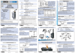
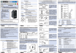
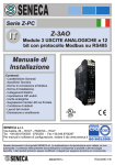
1
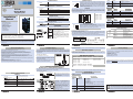
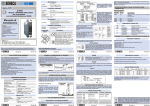
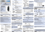
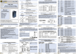
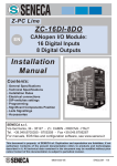
ALIMENTAZIONE
ALIMENTAZIONE
10 ..40 VDC
Tensione
19 ..28 VAC a 50 ..60 Hz
19 - 28 V
10 - 40 V
Tipico: 1.5 W, Max: 2.5 W
Assorbimento
Serie
Serie Z-PC
Z-PC
IT
In alternativa alla connessione mediante bus Z-PC-DINx, è
possibile usare i morsetti 2..3 per fornire l'alimentazione al modulo.I
Iimiti superiori non devono essere superati, pena gravi danni
al modulo.Nel caso in cui la sorgente di alimentazione non sia
protetta contro il sovraccarico, è necessario inserire un fusibile
nella linea di alimentazione: valore massimo ammesso 0.5 A.
2
3
CONDIZIONI AMBIENTALI
Z-D-IN
Modulo 5 INGRESSI DIGITALI
con protocollo Modbus su RS485
Temperatura
-10 ..+65°C
Umidità
30 ..90% a 40°C non condensante
Altitudine
Fino a 2000 m s.l.m.
Temperatura di
stoccaggio
-20 ..+85°C
INGRESSI DIGITALI
Ai morsetti di ingresso possono essere collegati sensori di tipo REED, PROXIMITY PNP ,
NPN, contatto. L'alimentazione per questi sensori può essere prelevata direttamente dal
morsetto 12 (+16 V). Tutti gli ingressi sono collegati in comune al morsetto 1 (GND). La
corrente che scorre attraverso un ingresso chiuso è di circa 3 mA.
Z-D-IN-1
16V
Grado di Protezione
IP20
7
CONNESSIONI
Manuale di
Installazione
Connessioni
8
#2
9
#3
Connettore posteriore IDC10 per barra DIN 46277
10
#4
11
#5
+
Dimensioni
L: 100 mm; H: 112 mm; W: 17,5 mm
Contenitore
PBT, colore nero
ISOLAMENTI
ISOLAMENTI
MODBUS RS485
Lo strumento è conforme alle seguenti normative:
EN61000-6-4/2002-10 (emissione
elettromagnetica, in ambiente industriale).
EN61000-6-2/2006-10 (immunità
elettromagnetica, in ambiente industriale).
EN61010-1/2001 (sicurezza). Tutti i circuiti
devono essere isolati con doppio isolamento
dai circuiti sotto tensione pericolosa.
Il trasformatore di alimentazione deve essere
a norma EN60742: “Trasformatori di
isolamento e trasformatori di sicurezza”.
SENECA s.r.l.
Via Germania, 34 - 35127 - Z.I. CAMIN - PADOVA - ITALY
Tel. +39.049.8705355 - 8705359 - Fax +39.049.8706287
Per manuali e software di configurazione, visitare il sito www.seneca.it
GND
B(-)
A(+)
Collegamento per la comunicazione RS485 con il sistema master
Modbus in alternativa al bus Z-PC-DINx.
N.B. L’indicazione della polarità della connessione RS485 non è
standardizzata, su alcuni master potrebbe essere invertita.
4
5
6
40006
TOTAL 4
Totalizzatore a 16 bit dell’ingresso 4. L’overflow
viene segnalato sul bit 40002.11
40007
TOTAL 5
Totalizzatore a 16 bit dell’ingresso 5. L’overflow
viene segnalato sul bit 40002.12
Input status
Nome
Registro
Descrizione
10001
INPUT 1
Stato attivo dell’ingresso 1. Vedi 40009.0
10002
INPUT 2
Stato attivo dell’ingresso 2. Vedi 40009.0
10003
INPUT 3
Stato attivo dell’ingresso 3. Vedi 40009.0
10004
10005
INPUT 4
INPUT 5
Stato attivo dell’ingresso 4. Vedi 40009.0
Stato attivo dell’ingresso 5. Vedi 40009.0
Coil register
Nome
Registro
Descrizione
00017
OFFTOTAL 1
Overflow del totalizzatore dell’ingresso 1
00018
OFFTOTAL 2
Overflow del totalizzatore dell’ingresso 2
00019
OFFTOTAL 3
Overflow del totalizzatore dell’ingresso 3
00020
00021
OFFTOTAL 4
OFFTOTAL 5
Overflow del totalizzatore dell’ingresso 4
Overflow del totalizzatore dell’ingresso 5
Segnalazioni tramite LED
Lunghezza bus Lunghezza
derivazione
1200 m
2m
ITALIANO 3/8
MI002053-I-E
Caratteristiche Generali
LED
STATO
Significato dei LED
PWR
Acceso fisso
FAIL
Lampeggiante
Acceso fisso
Lampeggiante
Acceso fisso
Lampeggiante
Acceso fisso
Il dispositivo è alimentato correttamente.
Impostazioni errate.
Anomalia o guasto.
Ricezione pacchetto avvenuta.
Verifica connessione.
Ricezione pacchetto avvenuta.
Verifica connessione.
RX
TX
ITALIANO 5/8
MI002053-I-E
MI002053-I-E
Per le massime prestazioni si raccomanda l’utilizzo di cavi schermati speciali, quali ad
esempio il BELDEN 9841.
Norme di Installazione
massima 10 KHz.
? Possibilità di configurazione ON-LINE.
? Comunicazione seriale RS485 con protocollo Modbus-Rtu, massimo 32 nodi.
? Isolamento degli ingressi 1500 Vac rispetto ai restanti circuiti in bassa tensione.
? Cablaggio facilitato dell'alimentazione e del collegamento seriale per mezzo di un bus
alloggiabile nella guida DIN.
? Inserimento ed estrazione dal bus senza interruzione della comunicazione o
dell'alimentazione del sistema.
? Tempi di comunicazione inferiori a 10 ms (@ 38400 Baud).
? Distanza di collegamento fino a 1200 m.
? Dip-Switch per settare indirizzo e baudrate del modulo, e per attivare o meno la
terminazione della linea RS485.
Totalizzatore a 16 bit dell’ingresso 3. L’overflow
viene segnalato sul bit 40002.10
Schema 1
ITALIANO 1/8
? 5 ingressi digitali con negativo comune autoalimentati 16 VDC.
2.
? Morsetti estraibili sezione 2.5 mm
? Protezione ingressi mediante soppressori di transienti TVS da 600 W/ms.
? 5 ingressi con contatore a 16 bit con frequenza massima 100 Hz, con filtro impostabile.
? Possibilità di impostare l’ingresso n°5 come contatore veloce a 32 bit con frequenza
TOTAL 3
Norme di connessione al Modbus
1) Installare i moduli nella guida DIN (max 120)
2) Connettere i moduli remoti usando cavi di lunghezza appropriata. Nella seguente tabella si
riportano i seguenti dati relativi alla lunghezza dei cavi:
-Lunghezza bus: lunghezza massima della rete Modbus in funzione del Baud Rate. Essa è la
lunghezza dei cavi che collegano i due moduli su cui è stata inserita la terminazione del bus
(vedere Schema 1).
-Lunghezza derivazione: lunghezza massima di una derivazione (vedere Schema 1) in
funzione del Baud Rate.
Questo documento è di proprietà SENECA srl. La duplicazione e la riproduzione sono vietate, se non
autorizzate. Il contenuto della presente documentazione corrisponde ai prodotti e alle tecnologie
descritte. I dati riportati potranno essere modificati o integrati per esigenze tecniche e/o commerciali.
MI002053-I-E
input #5: 0..10 KHz
1
NORMATIVE
1500 VAC a tre punti:
Input #1: 0..100 Hz
Input #2: 0..100 Hz
Input #3: 0..100 Hz
Input #4: 0..100 Hz
Input #5: 0..100 Hz
#1
Morsetti a vite sfilabili a 3 vie, passo 5,08 mm
INGOMBRI / CONTENITORE
Contenuti:
- Caratteristiche Generali
- Specifiche Tecniche
- Norme di Installazione
- Collegamenti Elettrici
- Norme di connessione al Modbus
- Impostazione DIP-switch
- Ingressi digitali
- Segnalazioni tramite LED
- Parametri di fabbrica
12
40005
Il modulo è progettato per essere montato su guida DIN 46277, in posizione verticale. Per un
funzionamento ed una durata ottimali, assicurare un’adeguata ventilazione, evitando di
posizionare canaline o altri oggetti che occludano le feritoie di ventilazione. Evitare il
montaggio dei moduli sopra ad apparecchiature che generano calore; è consigliabile il
montaggio nella parte bassa del quadro.
Impostazione DIP-switch
STATO DEI DIP SWITCH
Come illustrato in figura:
1) Inserire il connettore posteriore IDC10 del
modulo su uno slot libero della guida DIN
(l’inserimento è univoco essendo i connettori
polarizzati).
2) Per fissare il modulo nella guida DIN stringere i
due ganci posti ai lati del connettore posteriore
IDC10.
POSIZIONE BAUD RATE POSIZIONE INDIRIZZO
POSIZIONE TERMINATORE
00xxxxxxxx
9600
xx000001xx # 1
xxxxxxxxx0 Disabilitato
01xxxxxxxx
19200
xx000010xx # 2
xxxxxxxxx1 Abilitato
10xxxxxxxx
38400
11xxxxxxxx
57600
.....
.....
Parametri di fabbrica
Tutti i DIP-switch in OFF:
La posizione dei DIP-switch definisce i parametri di comunicazione Modbus del modulo:
Indirizzo e Baud Rate. Nella tabella seguente si riportano i valori del Baud Rate e
dell’Indirizzo in funzione dell’impostazione dei DIP-switch:
Inserimento nella guida DIN
ITALIANO 7/8
xx111111xx # 63
- Protocollo Modbus: - Parametri di comunicazione: 38400 8,N,1 Addr. 1
- Inversione stato degli ingressi : DISABILITATO
- Filtro digitale : 3 ms
- Totalizzatori : verso l’alto
- Canale a 10 KHz : DISABILITATO
- Tempo di latenza del Modbus : 5 ms
Per qualsiasi variazione dei parametri sono disponibili nell’area download del sito internet
www.seneca.it i software di comunicazione Z-NET e EASY-Z-PC.
Per maggiori informazione riguardo la lista di tutti i registri e le loro funzioni consulrare il
manuale UTENTE.
POSIZIONE BAUD RATE POSIZIONE INDIRIZZO
xx000000
Collegamenti Elettrici
From EEprom xx000000
From EEprom
ALIMENTAZIONE ED INTERFACCIA MODBUS
Alimentazione ed interfaccia Modbus sono disponibili utilizzando il bus per guida DIN
Seneca, tramite il connettore posteriore IDC10, o l’accessorio Z-PC-DINAL2-17.5.
Nota: quando i DIP da 3 a 8 sono in OFF, le impostazioni di comunicazione sono prese
da EEprom
Ingressi digitali
REGISTRI MODBUS
Connettore Posteriore (IDC10)
Specifiche Tecniche
RS485 GND
Power Supply AC +
Power Supply AC-
RS485 A
INGRESSI
1
Tipo di ingressi supportati
Reed, Contatto, Proximity PNP,
NPN (con resistenza esterna) ecc...
Numero Canali
5 (4+1)
Massima Frequenza Contatori
10 kHz solo per l’ingresso 5, se impostato
UL (stato OFF)
0 ..10 VDC , I < 2 mA
UH (stato ON)
12 ..30 VDC, I > 3 mA
Corrente assorbita
3 mA (per ciascun ingresso attivo)
MI002053-I-E
RS485 B
In figura si riporta il significato dei vari
pin del connettore IDC10 nel caso in
cui si desideri fornire i segnali
direttamente tramite esso.
IDC 10
Registro
40002
Utilizzo Accessorio Z-PC-DINAL2-17.5
Nel caso di utilizzo dell’accessorio ZPC-DINAL2-17.5, i segnali possono
essere forniti tramite morsettiere.
In figura si riporta il significato dei vari
morsetti e la posizione del DIP-switch
(presente in tutti i supporti per guida
DIN elencati in Accessori) per la
terminazione della rete CAN (non
usata nel caso di rete Modbus).
GNDSHLD: Schermo per proteggere i
cavi di connessione (consigliato).
ITALIANO 2/8
Holding register
MI002053-I-E
ITALIANO 4/8
Descrizione
Nome
OVERFLOW,
INPUT
Ingresso 1: 40002.0
Ingresso 2: 40002.1
Ingresso 3: 40002.2
Ingresso 4: 40002.3
Ingresso 5: 40002.4
I bit da 40002.8 a 40002.12 indicano
l'overflow dei rispettivi totalizzatori.
NOTA:I bit di overflow DEVONO essere
resettati da master.
40003
TOTAL 1
Totalizzatore a 16 bit dell'ingresso 1. L'overflow
viene segnalato sul bit 40002.8
40004
TOTAL 2
Totalizzatore a 16 bit dell'ingresso 2. L'overflow
viene segnalato sul bit 40002.9
MI002053-I-E
ITALIANO 6/8
Smaltimento dei rifiuti elettrici ed elettronici (applicabile nell’Unione Europea e negli altri paesi con raccolta
differenziata). Il simbolo presente sul prodotto o sulla confezione indica che il prodotto non verrà trattato come rifiuto
domestico. Sarà invece consegnato al centro di raccolta autorizzato per il riciclo dei rifiuti elettrici ed elettronici.
Assicurandovi che il prodotto venga smaltito in modo adeguato, eviterete un potenziale impatto
negativosull’ambiente e la salute umana, che potrebbe essere causato da una gestione non conforme dello
smaltimento del prodotto. Il riciclaggio dei materiali contribuirà alla conservazione delle risorse naturali. Per
ricevere ulteriori informazioni più dettagliate Vi invitiamo a contattare l’ufficio preposto nella Vostra città, il servizio
per lo smaltimento dei rifiuti o il fornitore da cui avete acquistato il prodotto.
MI002053-I-E
ITALIANO 8/8
POWER SUPPLY
POWER SUPPLY
Terminals 2 and 3 can be used to provide the module with power
supply as an alternative to connection using the Z-PC-DINx bus.The
upper limits mus not be exceeded as this can seriously damage
the module. If the power supply source is not protected against
overload, a safety fuse with a max. permissible value of 0.5 A must be
installed in the power supply line.
10 ..40 VDC
Voltage
19 ..28 VAC a 50 ..60 Hz
Typical: 1.5 W, Max: 2.5 W
Consumption
Z-PC
Z-PC Line
Line
2
3
19 - 28 V
10 - 40 V
ENVIRONMENTAL CONDITION
Z-D-IN
EN
Modbus Module
5 Digital Inputs
Temperature
-10 ..+65°C
Humidity
30 ..90% a 40°C non condening
Altitude
Up to 2000 m a.s.l.
Storage
Temperature
-20 ..+85°C
INPUTS
REED, PROXIMITY PNP, NPN, and contact-type sensor can be connected to the input
terminals. The power supply for these sensors can be taken directly from terminal 12 (+16 V).
All the inputs are connected in shared connection to terminal 1 GND. The current that flows
through a closed input is approx. 3 mA.
Z-D-IN-1
16V
Protection
IP20
7
CONNECTIONS
Installation
Manual
Connections
8
#2
9
#3
Rear IDC10 connector for DIN 46277 rail
10
#4
11
#5
+
Dimensioni
L: 100 mm; H: 112 mm; W: 17,5 mm
Contenitore
PBT, colore nero
ISOLAMENTI
ISOLATIONS
MODBUS RS485
The module complies with the following standards:
EN61000-6-4/2002-10 (electromagnetic
emission, industrial environment).
EN61000-6-2/2006-10 (electromagnetic
immunity, industrial environment)
EN61010-1/2001 (safety). All circuits must be
isolated from the other circuits under
dangerous voltage with double isolation. The
power supply transformer must comply with
En60742: “Isolated transformers and safety
transformers”.
SENECA s.r.l.
Via Germania, 34 - 35127 - Z.I. CAMIN - PADOVA - ITALY
Tel. +39.049.8705355 - 8705359 - Fax +39.049.8706287
For manuals and configuration software, see www.seneca.it
Connection for RS485 communication using the Modbus master
system as an alternative to the Z-PC-DINx bus.
Note: the indication of the RS485 connection polarity is not
standardised and in some masters may be inverted.
4
5
6
GND
B(-)
A(+)
40006
TOTAL 4
16 bit totalizer of input 1 . The overflow
is signalled on bit 40002.11
40007
TOTAL 5
16 bit totalizer of input 1 . The overflow
is signalled on bit 40002.12
Input status
Name
Register
INPUT 1
Active status input 1. See 40009.0
10002
INPUT 2
Active status input 2. See 40009.0
10003
INPUT 3
Active status input 3. See 40009.0
10004
10005
INPUT 4
INPUT 5
Active status input 4. See 40009.0
Active status input 5. See 40009.0
Coil registers
Name
Register
Description
00017
OFFTOTAL 1
Overflow input 1 totalizer.
00018
OFFTOTAL 2
Overflow input 2 totalizer.
00019
OFFTOTAL 3
Overflow input 3 totalizer.
00020
00021
OFFTOTAL 4
OFFTOTAL 5
Overflow input 4 totalizer.
Overflow input 5 totalizer.
LED
STATE
Meaning of LEDS
PWR
FAIL
On
Blinking
On
Blinking
On
Blinking
On
Power supply presence.
Error settings.
Fault/Failure.
Recived data from RS485.
Verify the connection.
Recived data from RS485.
Verify the connection.
RX
TX
Drop lenght
Bus lenght
Description
10001
2m
Scheme 1
ENGLISH 1/8
ENGLISH 3/8
MI002053-I-E
Installation Rules
General Specifications
housed in the DIN guide.
? Insertion and extraction of bus without interruption of communication or system power
supply.
? Communication times below 10 ms (@ 38400 Baud).
? Connection distance up to 1200 m.
? DIP-Switch settings for Modbus speed and address, and for RS485 line termination.
16 bit totalizer of input 1 . The overflow
is signalled on bit 40002.10
LEDS Signallings
1) Install the modules on the DIN rail (max 120).
2) Connect the remote modules using cables of proper length. On the table the following data
about the cables length are provided:
-Bus Length: Modbus network maximum length as a function of the Baud Rate. It is the lenght
of the cables which connect the two bus terminators modules (see Scheme 1).
-Drop Length: maximum length of a drop line (see Scheme 1) as a function of the Baud Rate.
1200 m
? 5 digital inputs with self-powered 16 VDC shared negative pole.
2
? Removable terminals with section of 2.5 mm
? Input protection by 600 W/ms TVS transient current suppressers.
? 5 inputs with 16 bit contactor with 100 Hz max. frequency, with settable filter.
? Possibility to set the input n° 5 for fast totalizer with 32bit, max frequency 10 KHz.
? Possibility of ON-LINE configuration.
? RS485 serial communication with Modbus-Rtu protocol, maximum 32 nodes.
? 1500Vac input insulation with respect to remaining low voltage circuits.
? Power supply and serial connection wiring facilitated by means of a bus that can be
TOTAL 3
Modbus connection rules
This document is property of SENECA srl. Duplication and reprodution are forbidden, if not authorized.
Contents of the present documentation refers to products and technologies described in it. All technical data
contained in the document may be modified without prior notice Content of this documentation is subject to
periodical revision.
MI002061-I-E
input #5: 0..10 KHz
1
STANDARDS
1500 VAC a tre punti:
Input #1: 0..100 Hz
Input #2: 0..100 Hz
Input #3: 0..100 Hz
Input #4: 0..100 Hz
Input #5: 0..100 Hz
#1
Removable 3-way crew terminals, 3,5 pitch
DIMENSIONS / BOX
Contents:
- General Specifications
- Technical Specifications
- Installation Rules
- Electrical connections
- Modbus connection rules
- DIP-switches settings
- Digital inputs
- Leds Signallings
- Factory Settings
12
40005
The module is designed to be installed in vertical position on a DIN 46277 rail. In order to
ensure optimum performance and the longest working life, the module(s) must be supplied
adequate ventilation and no raceways or other objects that obstruct the ventilation slots.
Never install modules above sources of heat; we recommend installation in the lower part of
the control panel.
ENGLISH 5/8
MI002053-I-E
For the best performances, the use of special shielded cables is recommended (BELDEN
9841 cable for example).
DIP SWITCH STATUS
Electrical Connections
POSITION
BAUD RATE POSITION ADDRESS
POSITION
00xxxxxxxx
9600
xx000001xx # 1
xxxxxxxxx0 Disable
01xxxxxxxx
19200
xx000010xx # 2
xxxxxxxxx1 Enable
10xxxxxxxx
38400
Factory settings
11xxxxxxxx
57600
POSITION
BAUD RATE POSITION ADDRESS
xx000000
From EEprom xx000000
- Modbus Protocol / - Communication parameters: 38400 8,N,1 Addr. 1
- Inversion input status : DISABLE
- Digital filter : 3 ms
- Totalizators : UP counter
- 10 KHz Channel : DISABLE
- Modbus latency time : 5 ms
TERMINATOR
.....
.....
ENGLISH 7/8
All DIP-switch OFF:
DIP-switch settings
The DIP-switches position defines the module Modbus communication parameters: address
and Baud Rate. In the following figure the Baud Rate and address values are listed as a
function of the DIP-switches position:
Inserting on the DIN rail
As it is illustrated in the next figure:
1) Insert the rear IDC10 connector on a DIN rail
free slot (the inserting is univocal since the
connectors are polarized).
2) Tighten the two locks placed at the sides of the
rear IDC10 connector to fix the module.
MI002053-I-E
xx111111xx # 63
Variation of standard parameters are possible by using configuration software Z-NET and
EASY-Z-PC (www.seneca.it).
For more information about a list of all register and their function consult the USER
manual.
From EEprom
POWER SUPPLY AND MODBUS INTERFACE
Power Supply and Modbus interface are available by using the bus for the Seneca DIN rail, by
the rear IDC10 connector or by Z-PC-DINAL1-17.5 accessory.
Note: when switches from 3 to 8 are in OFF, comunication settings are retrieved from
EEprom
Rear Connector (IDC10)
Technical Specifications
RS485 GND
Power Supply AC-
RS485 A
INPUTS
1
Type input
Reed, Contact, Proximity PNP,
NPN (with external resistor) etc...
Number of Channels
5 (4+1)
Maximum Counters frequency
10 KHz only for 5 if setted
UL (state OFF)
0 ..10 VDC , I < 2 mA
UH (state ON)
12 ..30 VDC, I > 3 mA
Absorbed Current
3 mA (for each input)
MI002053-I-E
RS485 B
Digital Inputs
MODBUS REGISTER
Power Supply AC +
In the figure the meaning of the IDC10
connector pins is showed, in the case
the user decides to provide the signals
directly through it.
IDC 10
Holding register
Register
40002
Z-PC-DINAL2-17.5 Accessory Use
In case of Z-PC-DINAL2-17.5
accessory use, the signals may be
provided by terminal blocks. The
figure shows the meaning of the
terminals and the position of the DIPswitch (present on each DIN rail
supports listed on Accessories) for
network termination (not used in case
of Modbus network).
GNDSHLD: Shield to protect the
connection cables ( recommended).
ENGLISH 2/8
MI002053-I-E
ENGLISH 4/8
Description
Name
OVERFLOW,
INPUT
Input 1: 40002.0
Input 2: 40002.1
Input 3: 40002.2
Input 4: 40002.3
Input 5: 40002.4
The bits from 40002.8 a 40002.12 indicate overflow of
the respective totalizers.
NOTE: The overflow bits MUST be reset from master.
40003
TOTAL 1
16 bit totalizer of input 1 . The overflow
is signalled on bit 40002.8
40004
TOTAL 2
16 bit totalizer of input 1 . The overflow
is signalled on bit 40002.9
MI002053-I-E
ENGLISH 6/8
Disposal of Electrical & Electronic Equipment (Applicable throughout the European Union and other European
countries with separate collections programs). This symbol, found on your producr or on its packaging, indicates
that this product should not be treated as household waste when you wish to dispose of it. Instead, it should be
handed over to an applicable collection point for the recycling of electrical & electronic equipment. By ensuring this
product is didposed of correctly, you will help prevent potential negative consequences to the environment and
human health, which could otherwise be caused by inappropriate disposal of this product. The recycling of materials
will help to conserve natural resources. For more detailed information about the recycling of the product, please
contact your local city office, waste disposal service of the retail store where you purchased this product.
MI002053-I-E
ENGLISH 8/8