1
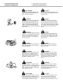
BARRIERE ARIA · ANNO 2010
AIR CURTAINS · YEAR 2010
BARRERAS DE AIRE · AÑO 2010
MANUALE UTENTE / USER’S MANUAL
MANUALE INSTALLATORE / INSTALLER’S MANUAL
MANUAL USUARIO / MANUAL INSTALADOR
Manuale di utilizzo e installazione per i seguenti modelli:
Usage and installation manual for the following models:
Manual de utilización y instalación para los siguientes modelos:
Tangenziali / Tangential / Tangenciales:
Assiali / Axial / Axiales:
T 06
A 06
T 12
A 12
T 09
T 15
A 09
A 15
Questo manuale è stato creato per scopo informativo. La ditta declina ogni responsabilità per i risultati di una progettazione o di una installazione basata sulle spiegazioni e le specifiche tecniche
riportate in questo manuale. E’ inoltre vietata la riproduzione anche parziale sotto qualsiasi forma dei testi e delle figure contenute in questo manuale.
This manual has been created for informative purpose. The company declines every responsibility for the results of projecting or installation based on the explanations and the technical specifications given in this manual. Is besides forbidden the reproduction under any form of the texts and of the figures contained in this manual.
Este manual fue creado con fines informativos. La empresa no acepta responsabilidades por los resultados de diseños o instalaciones basados sobre las explicaciones y las especificas tecnicas
contenidas en este manual. Es también prohibida la reproducción, aun parcial, bajo cualquier forma de los textos y figuras contenidos en este manual.
AIR CURTAINS
Serie / Series / Serie
Emissione / Issue /
Emissión
04-2005
Sostituise / Supersede
/ Remplace
03-2004
Catalogo / Catalogue / Catalogue
2
MUI1400950001
I prodotti elettrici ed elettronici di eventuale scarto non dovranno essere disposti con i normali rifiuti
domestici, ma smaltiti a norma di legge RAEE in base alle direttive Europee 2002/96/CE e successive
modifiche 2003/108/CE, informandosi presso il Comune di residenza o presso il rivenditore nel caso in
cui il prodotto venga sostituito con uno analogo.
Possible wasted electrical or electronic devices/products should not be located together with normal
domestic waste, but disposed according to the current WEEE law in compliance with the European
Directive 2002/96/EC and following modifications 2003/108/EC. Please inform yourself at your local
Administration or at your reseller in case the product will be replaced with a similar one.
Los productos eléctricos y electrónicos de eventual eliminación no deben ser eliminados con la basura
doméstica normal, pero dispuestos de acuerdo con la ley RAEE en conformidad con las Directivas
Europeas 2002/96/CE y modificaciones posteriores 2003/108/CE; consultarse con la Ciudad de residencia o con el revendedor si se sustituye el producto por otro similar.
ITALIANO
ENGLISH
3
INDICE / INDEX
1. Informazioni importanti / Important informations
1.1. Informazioni sulla sicurezza / Important safety information. . . . . . . . . . . . . . . . . . . . 5
2. Introduzione al prodotto / Product introduction
2.1. Dimensioni modello tangenziale / Tangential model dimensions . . . . . . . . . . . . . . . 6
2.2. Dimensioni modello assiale / Axial model dimensions . . . . . . . . . . . . . . . . . . . . . . . 7
3. Installazione / Installation
3.1. Precauzioni / Precautions . . . . . . . . . . . . . . . . . . . . . . . . . . . . . . . . . . . . . . . . . . . . . 8
3.2. Installazione a parete / Wall installation. . . . . . . . . . . . . . . . . . . . . . . . . . . . . . . . . . . 9
3.3. Installazione su acciaio e in controsoffitto /
Steelwork and ceiling installation . . . . . . . . . . . . . . . . . . . . . . . . . . . . . . . . . . . . . . . 10
4. Funzionamento e manutenzione / Operation and maintenance
4.1. Identificazione / Identification . . . . . . . . . . . . . . . . . . . . . . . . . . . . . . . . . . . . . . . . . . 11
4.2. Dati tecnici / Technical specifications. . . . . . . . . . . . . . . . . . . . . . . . . . . . . . . . . . . . 11
5. Schemi elettrici / Electrical layout
5.1. Modelli tangenziali / Tangential models . . . . . . . . . . . . . . . . . . . . . . . . . . . . . . . . . . 12
5.2. Modelli assiali / Axial models . . . . . . . . . . . . . . . . . . . . . . . . . . . . . . . . . . . . . . . . . . 13
4
1. INFORMAZIONI IMPORTANTI
1. IMPORTANT INFORMATIONS
1.1. Informazioni sulla sicurezza
1.1. Important safety informations
PRECAUZIONI
Non provare a installare l'unità da soli.
Questa unità richiede l'installazione da
parte di persone qualificate.
CAUTION
Do not attempt to install this unit by yourself. This unit requires installation by qualified personnel.
PERICOLO
Non provare da soli a fornire assistenza
alla macchina. Questa unità non ha
elementi di utilizzo che devono essere
aperti e la rimozione del coperchio può
esporvi a pericolosi voltaggi. Togliere l’
alimentazione non basta ad evitare possibili
shock elettrici.
DANGER
Do not attempt to service the unit by
yourself. This unit has no user serviceable components to be opened, and the
cover’s removing will expose you to dangerous voltage. Turning off the power supply
will not prevent from potential electric
shocks.
PERICOLO
Mai mettere le mani o oggetti nello sbocco
d'entrata e uscita dell'unità. Questa unità
contiene una ventola che gira ad alta
velocità. Un contatto con essa può causare serie lesioni.
DANGER
Never put hands or objects into the air
outlet of indoor and outdoor units. This
unit contain a fan running at high speed.
Contact with the moving fan will cause
serious injuries.
PERICOLO
Per evitare il rischio di serie scariche elettriche, mai spruzzare o versare acqua o
altri liquidi nell'unità.
DANGER
To avoid the risk of serious electrical
shock, never sprinkle or spill water or
liquid on the unit.
ATTENZIONE
Per prevenire una scarica elettrica, spegnere la corrente o staccare la spina
prima di iniziare ogni pulizia o altre varie
manutenzioni. Seguire le indicazioni per
la pulizia nel manuale utente.
WARNING
To prevent electric shock, turn off the
power or disconnect the power supply
plug before beginning any cleaning or
other routine maintenance. Follow the
cleaning directions in the owner's
manual.
ATTENZIONE
Non usare liquidi o aereosol per la pulizia. Usare un soffice e asciutto panno per
pulire l'unità. Per evitare scariche elettriche, mai provare a pulire l'unità spruzzando acqua su di essa.
WARNING
Do not use liquid cleaners or aerosol
cleaners. Use a soft and dry cloth for
cleaning the unit. To avoid electric
shocks, never attempt to clean the unit
by sprinkling water on it.
PRECAUZIONI
Non usare detergenti nell'unità. I solventi
possono velocemente distruggere gli elementi dell'unità (vaschetta di scarico e gli
elementi dello scambiatore di calore).
CAUTION
Do not use caustic household dry cleaners in the unit. Drain cleaners can
quickly destroy the unit components
(drain pan and heat-exchanger coil etc.).
5
2. INTRODUZIONE AL PRODOTTO
2. PRODUCT INTRODUCTION
2.1. Dimensioni modello tangenziale
2.1. Tangential model dimensions
Introduzione
Introduction
La barriera d'aria è un modello che ha le seguenti caratteristiche: alta efficienza, bassa rumorosità, struttura compatta e
modalità costruttive all'avanguardia.
Il risultato è un prodotto che si accoppia perfettamente con i
moderni sistemi di riscaldamento/climatizzazione, producendo
un effetto isolante tra l'interno e l'esterno di grande efficacia.
Si adatta perfettamente a qualsiasi luogo, come bar, ristoranti,
negozi, teatri etc.
This Air Curtain is a model having the following characteristic:
high efficiency, low noise, compact structure, and up-to-date
manufacturing procedures.
As a result, this model perfectly matches with the modern heating and cooling systems, and provides a very effective insulating effect between indoor and outdoor. Besides, it can be perfectly installed in any place such as pubs, restaurants, shops,
theaters and the like.
Dimensioni modello tangenziale / Tangential model dimensions
Piastra di montaggio / Mounting plate
Vista frontale / Front view
Presa d’aspirazione / Air inlet
Uscita aria
Vista posteriore / Rear view
Air outlet
Modello tangenziale
Tangential model
Fori di fissaggio / Installation bolt holes
Modello/Model
T 06
600
T 12
1200
T 09
T 15
6
A
900
1500
B
C
D
130
190
260
95
130
100
-
340
520
-
260
260
E
F
G
H
I
J
100
35
230
180
205
85
2. INTRODUZIONE AL PRODOTTO
2. PRODUCT INTRODUCTION
2.2. Dimensioni modello assiale
2.2. Axial model dimensions
Dimensioni modello assiale / Axial model dimensions
Modello assiale
Axial model
3-ø10
4-10 X 20
Fori di fissaggio
Mounting holes
Modello/Model
A
B
A 06
600
452
3
A 12
1200
1050
6
A 09
A 15
900
1500
750
1350
C
(numero motori/motors’ number)
5
8
7
3. INSTALLAZIONE
3. INSTALLATION
Interno / Indoor
8
3.1. Precauzioni
3.1. Precautions
Precauzioni
Precautions
Per l'installazione seguire attentamente la procedura di seguito riportata.
Follow these instructons to install the
Air Curtain.
* Installare l'apparecchio su una
parete solida per un montaggio in
sicurezza ed evitare vibrazioni.
* Install the unit in a sturdy place to
avoid shakings and ensure its security.
* Installare la barriera assicurandosi
che la distanza dal soffitto sia di
almeno 100mm (A≥100 mm).
* Make sure that the distance from
the ceiling is at least 100mm
(A≥100mm).
* Non installare l'apparecchio ad una
altezza superiore ai 3m, altrimenti l'effetto barriera potrebbe essere limitato.
* Do not install the equipment higher
than 3m to avoid a performance
reduction.
* Se l'apertura è maggiore della
laghezza della barriera, installare
due o più barriere affiancate mantenendo tra le varie apparecchiature
una distanza di 20 cm.
* When the entrance is wider than
the air curtain, it is recommended to
install two or more units in parallel.
In this case, keep a 20-40mm distance among the air curtain units.
* Non lasciare spazio tra la barriera e il
muro. Per il fissaggio a soffitto usare
l'apposita staffa di fissaggio.
* Do not allow gaps between the air
curtain and the wall. When hanging it
from the ceiling, use the provided ceiling brackets.
* Non installare l'apparecchio in presenza di forte umidità, vapore, liquidi, sostanze esplosive o corrosive.
* Do not install the unit in a place
where it is splashed by water or exposed to excessive steam, explosive
gas or corrosive gas.
esterno / outdoor
3. INSTALLAZIOME
3. INSTALLATION
3.2. Installazione a parete
3.2. Wall installation
Corpo
Unit body
Piastra fissaggio
Mounting plate
Installazione su pareti di calcestruzzo
Concrete wall installation
* Rimuovere la piastra di fissaggio.
Può essere fatto rimuovendo le viti
dal retro dell'apparecchio.
* Remove the mounting plate It can
be removed by unclamping the
screws on the back of main body.
* Fissare le viti nella posizione stabilita e cementare i fori. (Posizionare
la piastra di fissaggio)
* Fix the bolts in the proper positions. (Decide the position with the
mounting plate and pour cement
into the bolt holes).
* Dopo aver eseguito I fori fissare la piastra di montaggio alla parete.
* Once the cement has dried, fit the
mounting plate (use the appropriate
washers and nuts).
* Installare l'apparecchio inserendolo
dall'alto nelle estremità della piastra
di fissaggio.
* Install the equipment by inserting it
from the above onto the upper end of
the mounting plate as shown.
Installazione su parete in legno
Wooden wall installation
* Fissare la piastra nella posizione
stabilita.
* Fix the mounting plate in the proper
positions by means of the tapping
screws.
* Installare l'apparecchio inserendolo
dall'alto nelle estremità della piastra
di fissaggio.
* Install the equipment by inserting it
from the above onto the upper end of
the mounting plate as shown.
Vite regolazione inclinazione
Angle adjustment screw
40 - 50 mm
Cemento / Cement
13 - 15 mm
70 mm
Rondella / Washer
Piastra fissaggio
Mounting plate
Piastra fissaggio / Unit body
Circa / Approx
Vite regolazione inclinazione
Angle adjusment screw
Rondella / Washer
Vite / Screw
Piastra fissaggio / Unit body
Piastra fissaggio / Unit body
Circa / Approx
Vite regolazione inclinazione
Angle adjusment screw
9
3. INSTALLAZIONE
3. INSTALLATION
3.3. Installazione su acciaio e in controsoffitto
3.3. Steelwork and ceiling installation
Installazione su acciaio
Steelwork installation
Installazione in controsoffitto
Ceiling installation
4. FUNZIONAMENTO E MANUTENZIONE
4. OPERATION AND MAINTENANCE
Funzionamento
Operation
1. Premere il pulsante di accensione.
2. Regolare la velocità con il pulsante o con il telecomando.
3. Regolare l'inclinazione dell'apparecchio a richiesta.
1. Turn the power switch on.
2. Set the switch on Hi or Lo position by your hand or the
remote control.
3. Adjust the grate to obtain the best effect.
Piastra
fissaggio
Unit body
Vite regolazione inclinazione
Angle adjusment screw
Piastra
fissaggio
Unit body
Vite regolazione inclinazione
Angle adjusment screw
Manutenzione
Maintenance
1. Togliere l'alimentazione prima di fare manutenzione.
2. Usare una tensione di alimentazione adeguata alle esigenze
dell'apparecchio.
3. Non usare detergenti aggressivi o acidi per la pulizia
dell’apparecchio.
4. Evitare di fare entrare acqua nell'apparecchio.
1. Disconnect the power source before carrying on the maintenance.
2. Use the unit at the rated voltage and frequency as indicated
on the nameplate.
3. Never use petrol,benzese,thinner or any other similar chemicals for clearing the air curtain.
4. Do not allow water enter the motor.
5. When the power supply comes from socket, the plug has to
comply with IEC335-1.
10
4. FUNZIONAMENTO E MANUTENZIONE
4. OPERATION AND MAINTENANCE
Q
R
4.1. Identificazione
4.1. Identification
Identificazione
Identification
A
B
C
D
Modello
Potenza assorbita in W
Portata d’aria in m3/h
Velocità aria in m/sec
A
B
C
D
Model
Power input in W
Air flow in m3/h
Air speed in m/sec
P
Q
R
Numero di matricola unità inter
Marchio del rivenditore
Marchio CE
P
Q
R
Indoor unit serial number
Distributor brand name
CE marking
Identificazione CE
Il climatizzatore è marcato CE secondo
quanto dettato dalla Comunità Europea,
con le Direttive 89/392/CEE, 73/23/CEE,
89/336/CEE, e successive modifiche.
CE identification
The air conditioner is marked CE as established by the European Union in
89/392/ECC, 73/23/ECC, 89/336/ECC
Directives and subsequent modifications.
Important note
Nota Importante
L’utilizzo della barriera d’aria per scopi
diversi da quelli previsti, e non conformi a quanto descritto in questo manuale, farà decadere automaticamente
qualsiasi responsabilità diretta e/o indiretta della Ditta Costruttrice e del suoi
Distributori.
The use of the air curtains for purposes
other than those for which it has been
designed and built and failure to
comply with the instructions listed in
this manual shall relieve the
Manufacturer and its Distributors from
any direct and/or indirect responsibility.
4.2. Dati tecnici / Technical parameter
MODELLO
MODEL
Freq. Tens. Diametro
ventola
Freq. Volt. Diameter
of wheel
Hz
V
115
T 12
A 09
A 12
A 15
Rumorosità
Velocità aria
Peso
Dimensioni
Air volume
Noise
Air velocity
Weight
Dimensions
W
m /h
3
dB
m/s
Kg
LxHxP
Max/Hi Min/Low
Max/Hi
Max/Hi
Max/Hi
Min/Low
950
≤55
11
12
120
T 09
A 06
Portata aria
mm
T 06
T 15
Potenza
assorbita
Power input
220
140
230
280
50
80
136
130
160
215
100
120
180
250
70
120
145
195
1150
1750
2180
840
1400
1760
2240
≤57
≤58
≤59
≤48
≤51
≤53
≤56
11
17
600 x 215 x 215
900 x 215 x 215
11
20,5 1200 x 215 x 215
8,5
7,8
11
8,5
8,5
8,5
23,5 1500 x 215 x 215
600 x 220 x 157
11,2
900 x 220 x 157
18
1500 x 220 x 157
14,5 1200 x 220 x 157
Nota / Note
I valori di rumorosità sono rilevati attorno l’unità, ad una distanza di 1m.
The noise values were measured around the air curtain, from a distance of 1m inside the room.
11
5. SCHEMI ELETTRICI
5. ELECTRICAL LAYOUT
5.1. Modelli tangenziali
5.1. Tangential models
Modello a singola velocità
Single speed model
Modello a doppia velocità
Double speed model
Modello con telecomando
Remote controlling model
MATERIALI / MATERIALS:
DIS:
Codice / Code:
Schema elettrico modelli tangenziali
Tangential models electrical layout
12
N° Pezzi / N. Pieces:
REV:
SCALA / SCALE:
DATA / DATE: 15.01.2005
OGGETTO / OBJECT DISEGNO \ DRAWING:
QXD GRAPICS FORMAT
INDICE / INDEX:
Disegno proprietà della ditta - a termine di legge è fatto vietato riprodurlo o di renderlo comunque noto a terzi senza autorizzazione
Drawing property of the company - you may not copy, reproduce or transfer it to third parties without of the company authorization
5. SCHEMI ELETTRICI
5. ELECTRICAL LAYOUT
5.2. Modelli assiali
5.2. Axial models
Modello con comando a pulsante
Key-switch model
Modello con telecomando
Remote controlling model
Allacciamento
Wiring method
Cavo di alimentazione
Power cord
Terminali
Round contact terminal
Morsettiera
Terminal
Coperchio
Terminal cover
MATERIALI / MATERIALS:
DIS:
Codice / Code:
Schema elettrico modelli assiali
Axial models electrical layout
N° Pezzi / N. Pieces:
REV:
SCALA / SCALE:
DATA / DATE: 15.01.2005
OGGETTO / OBJECT DISEGNO \ DRAWING:
QXD GRAPICS FORMAT
INDICE / INDEX:
Disegno proprietà della ditta - a termine di legge è fatto vietato riprodurlo o di renderlo comunque noto a terzi senza autorizzazione.
Drawing property of the company - you may not copy, reproduce or transfer it to third parties without of the company authorization.
13
ESPAÑOL
14
ÍNDICE
1. Informaciones importantes
1.1. Informaciones sobre la seguridad . . . . . . . . . . . . . . . . . . . . . . . . . . . . . . . . . . . . . . 16
2. Introducción al producto
2.1. Tamaño modelo tangencial . . . . . . . . . . . . . . . . . . . . . . . . . . . . . . . . . . . . . . . . . . . 17
2.2. Tamaño modelo axial . . . . . . . . . . . . . . . . . . . . . . . . . . . . . . . . . . . . . . . . . . . . . . . 18
3. Instalación
3.1. Precaucciones . . . . . . . . . . . . . . . . . . . . . . . . . . . . . . . . . . . . . . . . . . . . . . . . . . . . . 19
3.2. Instalación en la pared. . . . . . . . . . . . . . . . . . . . . . . . . . . . . . . . . . . . . . . . . . . . . . . 20
3.3. Instalación en acero y en falso techo . . . . . . . . . . . . . . . . . . . . . . . . . . . . . . . . . . . 21
4. Funcionamiento y manutención
4.1. Identificación . . . . . . . . . . . . . . . . . . . . . . . . . . . . . . . . . . . . . . . . . . . . . . . . . . . . . . 22
4.2. Datos tecnicos . . . . . . . . . . . . . . . . . . . . . . . . . . . . . . . . . . . . . . . . . . . . . . . . . . . . . 22
5. Esquemas eléctricos
5.1. Modelos tangenciales . . . . . . . . . . . . . . . . . . . . . . . . . . . . . . . . . . . . . . . . . . . . . . . 23
5.2. Modelos axiales . . . . . . . . . . . . . . . . . . . . . . . . . . . . . . . . . . . . . . . . . . . . . . . . . . . . 24
15
1. INFORMACIONES IMPORTANTES
1.1. Informaciones sobre la seguridad
PRECAUCCIONES
No tratar de instalar la unidad por sí
mismo; esta unidad debe ser instalada
por personal calificado.
PELIGRO
No tratar de prestar asistencia a
la máquina por sí mismo; esta unidad no
tiene ningún elemento de utilización que
debe ser abierto y la remoción de la capa
puede exponer el usuario a tensiones
peligrosas. Quitar la alimentación no es
suficiente para evitar posibles descargas
eléctricas.
PELIGRO
Nunca poner las manos u objetos en el
punto de entrada y salida del aire de la
unidad; esta unidad contiene un ventilador
que gira a alta velocidad. El contacto con
el mismo puede causar lesiones graves.
PELIGRO
Para evitar el riesgo de descargas eléctricas graves, nunca rociar o derramar
agua u otros líquidos en la unidad.
CUIDADO
Para evitar una descarga eléctrica, apagar la corriente o desconectar el enchufe antes de cualquier operación de limpieza o mantenimiento de rutina.
Respectar las instrucciones en cuanto a
la limpieza contenidas en este manual.
CUIDADO
No utilizar líquidos o aerosoles para la
limpieza. Utilizar un paño suave y seco
para limpiar la unidad. Para evitar
descargas eléctricas, no intentar limpiar
la unidad rociando agua sobre la misma.
16
PRECAUCCIONES
No utilizar detergentes en la unidad. Los solventes pueden rápidamente
destruir los elementos de la unidad (la
bandeja de drenaje y los elementos del
intercambiador de calor).
2. INTRODUCCIÓN AL PRODUCTO
2.1. Tamaño modelo tangencial
Introducción
La barrera de aire es un modelo que tiene las siguientes
características: alta eficiencia, ruido bajo, diseño compacto y
métodos avanzados de construcción.
El resultado es un producto que se une a la perfección con los
sistemas modernos de calefacción/refrigeración, produciendo
un efecto de aislamiento entre el interior y el exterior de gran
eficacia.
Se adapta perfectamente a cualquier lugar, tales como bares,
restaurantes, tiendas, teatros, etc.
Tamaño modelo tangencial
Placa de montaje
Vista de frente
Toma aire
Salida aire
Vista posteriore / Rear view
t
Modelo tangencial
Agujeros de fijación
Modelo
A
T 06
600
T 12
1200
T 09
T 15
900
1500
B
C
D
130
190
260
95
130
100
-
340
520
-
260
E
F
G
H
I
J
100
35
230
180
205
85
260
17
2. INTRODUCCIÓN A EL PRODUCTO
2.2. Tamaño modelo axial
Tamaño modelo axial
Modelo axial
3-ø10
4-10 X 20
Agujeros de fijación
Modelo
A
B
A 06
600
452
3
A 12
1200
1050
6
A 09
A 15
18
900
1500
750
1350
C (nombre motores)
5
8
3. INSTALACIÓN
3.1. Precaucciones
Precaucciones
En cuanto a la instalación, respectar
las instrucciones a continuación.
* Instalar la unidad en una pared sólida para un montaje seguro y para
prevenir vibraciones.
* Instalar la barrera asegurandose de
que la distancia desde el techo sea
de al menos 100 mm (A ≥ 100 mm).
Interno / Indoor
esterno / outdoor
* No instalar la máquina a una altura
de más de 3 m, de lo contrario el
efecto barrera podría ser limitado.
* Si la apertura es mayor que la
anchura de la barrera, poner al lado
dos o más barreras manteniendo
entre los distintos equipos una distancia de 20 cm.
* No dejar espacio entre la barrera y
la pared. Para el montaje en la pared,
utilizar el soporte apropriado de fijación.
* No instalar el aparato en presencia
de alta humedad, vapor, líquido, substancias explosivas o corrosivas.
19
3. INSTALACIÓN
3.2. Instalación en la pared
Instalación en paredes de hormigón
Cuerpo
Placa montaje
* Retirar la placa de montaje; se
puede hacer quitando los tornillos de
la parte posterior del equipo.
Tornillo ajuste inclinación
40 - 50 mm
Hormigón
13 - 15 mm
* Fijar los tornillos en la posición establecida y cementar los agujeros (posicionar la placa de montaje).
70 mm
Rondana
* Después de perforar los agujeros,
fijar la placa de montaje en la pared.
Placa montaje
Placa montaje
* Instalar el equipo insertándolo
desde la parte superior en la extremidad de la placa de montaje.
Más o menos
Tornillo ajuste inclinación
Rondana
Instalación en la pared de madera
Tornillo
Placa montaje
Placa montaje
* Instalar el equipo insertándolo
desde la parte superior en la extremidad de la placa de montaje.
Más o menos
Tornillo ajuste inclinación
20
* Fijar la placa en la posición establecida.
3. INSTALACIÓN
3.3. Instalación en acero y en techo falso
Instalación en acero
Acero
Perno M8
Instalación en techo falso
Pared
Techo
Rejilla
4. FUNCIONAMIENTO Y MANUTENCIÓN
Funcionamiento
1. Presionar el botón de encendido.
2. Ajustar la velocidad por medio del botón o del mando a distancia.
3. Ajustar la inclinación del equipo como se desea.
Placa fijación
Placa fijación
Tornillo ajuste inclinación
Tornillo ajuste inclinación
Manutención
1. Quitar la alimentación antes de realizar el mantenimiento.
2. Utilizar una tensión de alimentación apropriada a las exigencias del equipo.
3. Nunca utilizar detergentes agresivos o ácidos para la limpieza del equipo.
4. No hacer entrar agua en el aparate.
21
4. FUNCIONAMIENTO Y MANUTENCIÓN
Q
R
4.1. Identificación
Identificación
A
B
C
D
Modelo
Potencia absorbida en W
Caudal aire en m3/h
Velocidad aire en m/sec
P
Q
R
Número matricula unidad interna
Marca del revendedor
Marca CE
Identificación CE
El climatizador es marcado CE según las
leyes de la Comunidad Europea, las
Directivas 89/392/CEE, 73/23/CEE,
89/336/CEE y modificaciones posteriores.
Nota importante
La utilización de la barrera de aire para
finalidades diferentes de las previstas
y que no cumplen con las instrucciones de este manual, anulará automáticamente cualquiera responsabilidad
directa y/o indirecta del Fabricante y de
sus Distributores.
4.2. Datos tecnicos
MODELO
Frec. Tens. Diámetro
rotor
Hz
V
115
T 12
T 15
A 06
A 09
A 12
A 15
220
Caudal aire
Ruido
W
m /h
3
dB
m/s
Kg
mm
T 06
T 09
Potencia
absorbida
Máx.
Mín.
Máx
Máx
Máx
Mín
120
100
950
≤55
11
12
140
230
280
50
80
136
130
160
215
120
180
250
70
120
145
195
1150
1750
2180
840
1400
1760
2240
≤57
≤58
≤59
≤48
≤51
≤53
≤56
NOTA:
Los valores del ruido han sido medidos alredador del equipo, con una distancia de 1m.
22
Velocidad aire Peso
11
17
Tamaño
LxHxP
600 x 215 x 215
900 x 215 x 215
11
20,5 1200 x 215 x 215
8,5
7,8
11
8,5
8,5
8,5
23,5 1500 x 215 x 215
600 x 220 x 157
11,2
900 x 220 x 157
18
1500 x 220 x 157
14,5 1200 x 220 x 157
5. ESQUEMA ELÉCTRICOS
5.1. Modelos tangenciales
Modelo con 1 sola velocidad
Modelo con doble velocidad
Modelo con mando a distancia
MATERIALES:
DIB:
Código
Esquema eléctrico modelos tangenciales
N° Piezas
REV:
ESCALA:
FECHA: 15.01.2005
OBJECTO DIBUJO:
QXD GRAPICS FORMAT
ÍNDICE:
Dibujo de propiedad de la empresa - en conformidad con la ley, está prohibido cualquiera reproducción o difusión sin previa autorización.
23
5. ESQUEMAS ELÉCTRICOS
5.2. Modelos axiales
Modelo con mando a botón
Modelo con mando a distancia
Conexiones
Cable de alimentación
Bornes
Terminaes de conexión
Capa
MATERIALES:
DIB:
Código:
Esquema eléctrico modelos axiales
N° Piezas:
REV:
ESCALA:
FECHA: 15.01.2005
OBJECTO DIBUJO:
QXD GRAPICS FORMAT
ÍNDICE:
Dibujo de propiedad de la empresa - en conformidad con la ley, está prohibido cualquiera reproducción o difusión sin previa autorización.
24
KEY (English)
Legenda (Español)
Black
Nigro
Brown
Marrón
Blu
Control
Display
Electrical box
Exhaust
Fan motor
Filter
Gray
Green
High
Indoor unit
Low
Outdoor unit
Overload
Panel
PE
Power
Pump
Pump motor
Receiver
Red
Superheat protection
Terminal
Transformer
Water
White
Yellow
25
Azul
Regulador
Pantalla
Caja eléctrica
Descarga
Motor ventilador
Filtro
Griso
Verde
Alto
Unidad interna
Bajo
Unidad externa
Sobrecarga
Panelo
Puesta a tierra
Alimentación
Bomba
Bomba motor
Recebidor
Rojo
Protección térmica
Borne
Transformador
Agua
Blanco
Amarillo