1
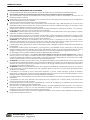
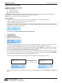
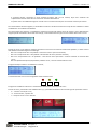
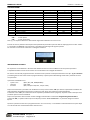
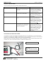
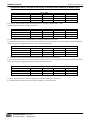
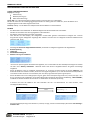
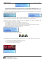
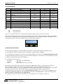
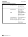
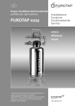
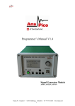
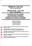
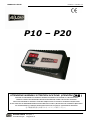
MANUALE UTENTE
Revisione n° 0 del 22/11/12
P10 – P20
ATTENZIONE! WARNING! ATTENTION! ACHTUNG! ¡ATENCIÓN!ご注意!
LEGGERE ATTENTAMENTE IL MANUALE OPERATIVO PRIMA DI UTILIZZARE IL CARICABATTERIA
CAREFULLY READ THE OPERATING INSTRUCTIONS BEFORE USING THE BATTERY CHARGER
LIRE ATTENTIVEMENT LE MANUEL D'INSTRUCTIONS AVANT D'UTILISER LE CHARGEUR DE BATTERIE
BITTE LESEN SIE DIE BEDIENUNGSANLEITUNG SORGFÄLTIG DURCH, BEVOR SIE DAS LADEGERÄT BENUTZEN
LEA ATENTAMENTE EL MANUAL OPERATIVO ANTES DE UTILIZAR EL CARGADOR DE BATERÍAS
必ず取扱説明書をお読みになってからご使用ください。
4LOAD GmbH
87700 Memmingen
Europastr. 9
[email protected]
MANUALE UTENTE
Revisione n° 0 del 22/11/12
INSTALLAZIONE E AVVERTENZE PER LA SICUREZZA
Errori di installazione ed utilizzo del caricabatteria possono determinare danni al caricabatteria ed incidenti all’operatore.
Solo personale specializzato ed autorizzato potrà eseguire interventi che richiedono l’apertura del caricabatteria.
Se il funzionamento in sicurezza del caricabatteria non può più essere garantito, fermare il caricabatteria e assicurarsi che non
possa essere rimesso in funzione.
Prima della messa in funzione del caricabatteria occorre verificare il buono stato delle guaine di isolamento dei cavi di collegamento
alla rete di alimentazione e dei cavi di batteria.
Premere il pulsante OK prima di effettuare il distacco della batteria.
Al fine di ridurre i rischi di incidente, caricare solo batterie di tipo Piombo Acido o Gel o AGM (assicurarsi che la curva di carica
selezionata sia adatta al tipo di batteria). Non cercare di caricare alcun altro tipo di batteria ricaricabile o non ricaricabile: queste
batterie possono esplodere, creando danni a cose o persone.
Studiare tutte le istruzioni di sicurezza specifiche indicate dal produttore della batteria, ad esempio se rimuovere, o non rimuovere,
i tappi degli elementi durante la carica e le modalità di carica consigliate.
ATTENZIONE !! La batteria genera gas esplosivi durante la carica. Nelle vicinanze delle batterie occorre quindi seguire le seguenti
avvertenze: non fumare ed evitare fiamme o scintille.
Evitare assolutamente di posizionare il caricabatteria nelle immediate vicinanze della batteria che deve essere caricata; Eventuali
gas prodotti/emessi dalla batteria durante la carica, corrodono e danneggiano il caricabatteria. Posizionare il caricabatteria il più
lontano possibile dalla batteria per quanto consentito da cavi di batteria.
ATTENZIONE !! La collocazione del caricabatteria deve avvenire tenendo in considerazione il fatto che lo stesso contiene
componenti elettrici/elettronici che possono produrre archi voltaici. Non deve essere esposto a pioggia, getti d'acqua, fonti di
vapore e lontano da fonti di calore. Soprattutto non deve essere installato in locali densi di polvere.
E’ assolutamente vietato posizionare e/o fissare il caricabatteria su piani di appoggio in materiali infiammabile (come mensole e/o
pareti di legno).
Per facilitare lo scambio termico del caricabatteria, e quindi garantire la sua affidabilità, occorre posizionarlo in modo che possa
scambiare facilmente calore con l’ambiente. Deve essere preferibilmente montato in posizione orizzontale (sfruttando i 4 fori di
fissaggio) e si deve garantire uno spazio di almeno 20÷30cm (12”) in corrispondenza della presenza delle ventole di areazione.
Per il montaggio a muro è possibile modificare la posizione delle bocchette di ventilazione.
Per evitare pericoli di folgorazione, il caricabatteria deve essere collegato ad una presa di corrente collegata a terra. Inoltre la
presa di corrente a cui si collega il caricabatteria deve essere proporzionata alla potenza assorbita dallo stesso e dovrà essere
protetta da apparecchiatura elettrica a norma (fusibili o interruttore automatico) dimensionata per una corrente almeno il 10%
superiore all’assorbimento di corrente dichiarato sulla matricola dell’apparecchio.
ATTENZIONE !! Controllare, prima di iniziare la carica, che l’apparecchio soddisfi la tensione della batteria, che la corrente di carica
sia appropriata alla capacità della batteria e che la curva di ricarica selezionata sia corretta per il tipo di batteria da caricare. Inoltre
verificare che la tensione di ingresso del caricabatteria indicata sui dati di targa soddisfi la tensione di alimentazione disponibile e
che l’impianto sia provvisto di messa a terra.
ATTENZIONE !! Verificare la compatibilità della spina rete in dotazione al caricabatteria. Il caricabatteria è fornito con uno spezzone
di cavo terminato con connettore IEC320-C14, al quale è possibile applicare il cavo rete con la spina idonea agli standard elettrici
per paese in cui è utilizzato.
Il caricabatteria non necessita di alcuna manutenzione particolare, a parte le normali operazioni di pulizia da effettuarsi
regolarmente e periodicamente in base alla tipologia dell’ambiente di lavoro. Prima di iniziare la pulizia dell’apparecchio, occorre
scollegare il cavo di alimentazione alla rete e i cavi di collegamento alla batteria.
La superficie esterna del caricabatteria può surriscaldarsi mentre il caricabatteria è in funzione e può rimanere calda anche dopo lo
spegnimento.
Il caricabatteria non deve essere utilizzato come componente critico in dispositivi per il supporto medico o altri sistemi senza
espressa approvazione scritta del costruttore.
La mancata osservanza di queste istruzioni nell’installazione e nell’uso del caricabatterie può pregiudicare la protezione fornita
dall’apparecchio e invalidare la garanzia del fabbricante.
Non consentire l’uso dell’apparecchio a persone (anche bambini) con ridotte capacità psico-fisico-sensoriali, o con esperienza e
conoscenze insufficienti, a meno che non siano attentamente sorvegliate e istruite da un responsabile della loro incolumità.
Sorvegliare i bambini, assicurandosi che non giochino con l’apparecchio.
Le specifiche menzionate in questo manuale sono soggette a cambiamenti senza preavviso. Questa pubblicazione sostituisce ogni
informazione precedentemente fornita.
4LOAD GmbH
87700 Memmingen
Europastr. 9
[email protected]
MANUALE UTENTE
Revisione n° 0 del 22/11/12
MANUALE D’USO PER L’UTENTE
ELEMENTI DI CONTROLLO E COMANDO
Display per visualizzare:
Corrente di carica (A)
Tensione batteria (U)
Barra stato carica in corso
Tasto “OK”: per entrare/confermare l’impostazione dei parametri di carica. E’ possibile fermare la carica premendo il
pulsante OK. Per riavviare occorre disconnettere la batteria e poi riconnetterla.
Tasti ↑ e ↓ : per scorrere il menù dei parametri di carica.
FUNZIONAMENTO
- Collegare il cavo rete allo spezzone di cavo presente sul caricabatteria con connettore IEC320-C14
- Inserire la spina del cavo di alimentazione in una presa di corrente.
- Collegare la batteria rispettando la polarità.
- A questo punto, sul display del carica batterie vengono visualizzate in sequenza diverse informazioni relative alla
programmazione interna del caricabatteria: con la scritta “4LOAD” viene presentata la versione del software
installato nel caricabatteria (ad es. U1.2):
Successivamente vengono visualizzati i parametri impostati per:
1.
2.
3.
4.
tensione di batteria,
corrente di carica,
modello di caricabatteria,
numero e tipo di curva di carica.
-
A questo punto viene eseguito un test sulla tensione di batteria per decidere se iniziare o meno il processo di carica
indicato con “Battery verification” , durante il quale viene eseguito un doppio lampeggio del led giallo.
Se la batteria non è connessa al caricabatterie sul display appare la scritta “Battery?”. La scritta permane anche in
caso di esito negativo del test come ad esempio, nel caso di polarità invertita, di batteria in Corto circuito o
connessione ad una batteria di tensione differente da quella programmata.
Se la batteria ha una tensione molto bassa, corrispondente a una tensione per Cella compresa tra 0,2 e 0,5 Vc (0,2 <
Vc < 0,5 V), il caricabatteria si pone in una condizione di anomalia e mostra sul display il messaggio “BATT.FAILURE”,
rimanendo in attesa del collegamento di una batteria di tensione corretta.
-
-
In questo caso l’operatore vede l’alternarsi ogni 2 secondi di due finestre come di seguito descritte
24V 20A
GEL
-
2 sec
24V 20A
Battery ?
Se la tensione di batteria non è compresa tra 1,4 e 2,4 Vc sul display appare la scritta “Out of Range - Confirm? OK
10s”
4LOAD GmbH
87700 Memmingen
Europastr. 9
[email protected]
MANUALE UTENTE
Revisione n° 0 del 22/11/12
E’ possibile attivare comunque la carica tenendo premuto “OK” per 10 secondi, dopo aver verificato che
l’impostazione del CB è coerente con la tensione nominale della batteria.
In questo caso il caricabatteria esegue un ciclo di carica a corrente costante pari alla corrente nominale per 30 min.
Se il test di batteria da esito negativo, il caricabatteria continua a verificare la tensione ai capi dei cavi di batteria in attesa
di identificare una condizione accettabile.
Se il test ha dato esito positivo, il caricabatteria visualizza la tensione di batteria prima di iniziare la carica della batteria,
vengono quindi visualizzati il valore della corrente (A), il valore della tensione (V) e la barra di stato della carica in corso.
Durante la carica, la riga inferiore visualizza, attraverso una barra scorrimento di massimo 16 quadretti, lo stato di carica
della batteria secondo la seguente simbologia:
- Barra con riempimento fino a 8 quadretti : Prima fase di carica (corrente costante)
- Barra con riempimento fino a 10 quadretti : Secondo fase di carica (Tensione costante)
- Barra con riempimento fino a 13 quadretti : Terza fase di carica (Corrente o Tensione costante in funzione della
curva)
- Barra completamente piena (16 quadretti) : Batteria carica, carica di mantenimento o Float
Di seguito esempio relativo a caricabatteria in Fase I1,
L’avanzamento del ciclo di carica è segnalato anche tramite tre led:
DL3
DL2
DL1
Di seguito una tabella che descrive le visualizzazioni led durante le diverse fasi di carica
Durante la carica, premendo il tasto “FRECCIA SU” (↑), è possibile visualizzare nella seconda riga altri parametri di carica
- C = numero di curva (da 1 a 4)
P= numero di fase, a partire da 1
- T = tempo di carica in ore e decimali
4LOAD GmbH
87700 Memmingen
Europastr. 9
[email protected]
MANUALE UTENTE
Revisione n° 0 del 22/11/12
VISUALIZZAZIONI
Rif.
Segnalazioni
Led DL3 (Rosso)
Led DL2 (giallo)
Alimentazione solo da rete
OFF
OFF
Start
Esecuzione Autostart
OFF
OFF
F1
Fase 1 : Carica iniziale a corrente costante
ON
OFF
F2
Fase 2 : Carica finale a tensione costante
OFF
ON
F3_I (*) Fase 3 : Carica finale a corrente costante
OFF
ON
F3_U (*) Fase 3 : Carica finale a tensione costante
OFF
ON
F4
Carica terminata
OFF
OFF
Anomalia distacco Batteria (10 sec)
ON
ON
Timout in fase o Eccesso di corrente
BLK
OFF
Mancanza Batteria
OFF
OFF
Inversione di polarità
OFF
OFF
Batteria in Corto
OFF
OFF
Tensione Batteria errata
OFF
OFF
Dove:
OFF =
il led è spento
ON =
il led è acceso fisso
Nota (*) : La sequenza delle fasi e delle relative segnalazioni differisce da curva a curva.
Led DL1 (Verde)
OFF
OFF
OFF
OFF
OFF
OFF
ON
ON
OFF
OFF
OFF
OFF
OFF
Durante la carica è possibile interromperla anticipatamente premendo il pulsante OK: sul display appare la scritta “STOP!”
e si accende il led VERDE di carica terminata, come descritto dalla figura di seguito riportata.
Per riavviare la carica occorre staccare e ricollegare la batteria.
IMPOSTAZIONI DI CARICA
Per impostare il caricabatteria in funzione della batteria da caricare occorre effettuare alcune piccole operazioni.
L’impostazione della curva di carica avviene con caricabatteria non collegato alla batteria.
Per entrare nel menù di programmazione è necessario tenere premuti contemporaneamente i tasti ↑ e ↓ per 1 secondo
(il Led DL2 giallo acceso indica la fase di programmazione) a questo punto utilizzando gli stessi tasti è possibile scorrere i
vari parametri.
I parametri modificabili sono:
- Tipo di curva
(WET, GEL, CAR, AGM/ODISSEY)
- Tensione
(12V, 24V)
- Corrente
(20A, 15A per il P20, 10 A, 5 A per il P10)
Dopo aver selezionato il parametro da modificare occorre premere il tasto “OK” per attivare la possibilità di modifica del
dato (segnalato dal Led Rosso DL3 acceso) e utilizzare i tasti ↑ e ↓ per impostare il valore desiderato.
Premere di nuovo “OK” per confermare il dato impostato (il Led Rosso DL3 si spegnerà). Inquesto modo uno dopo l’altro i
parametri possono essere modificati.
Dopo aver impostato i dati uscire dal menù di settaggio selezionando la schermata “Programming Save and Exit” e
premendo “OK”, in questo modo compare sul display la scritta “SAVE PARAMETERs” e i parametri vengono salvati in
Eprom.
Qualora l’operatore sia entrato in programmazione e non ne sia uscito, il caricabatteria automaticamente si riporta dopo
circa 30 secondi sulla visualizzazione dello stato di carica.
4LOAD GmbH
87700 Memmingen
Europastr. 9
[email protected]
MANUALE UTENTE
Revisione n° 0 del 22/11/12
MESSAGGI DI ERRORE SUL DISPLAY
In caso di anomalie possono essere visualizzati i seguenti codici di errore.
CODICE DI ERRORE
Srt:IB > IBmax
PROBLEMA
La corrente di uscita ha superato di
oltre il 10% il valore della corrente
nominale
E01:Open Circuit
La corrente è improvvisamente
andata a zero in modo inatteso
E03:timer T1
E’ scattato il timer di sicurezza della
fase 1
T1 : PreAllarm
Il caricabatteria non ha completato la
prima fase di carica in tempi standard
e proseguira per altre 3h prima di
andare in anomalia E03
SOLUZIONI
Verificare se non vi sono cortocircuiti
sulla batteria o sui cavi batteria, o se
vi sia un carico attivo sulla batteria
che assorbe più corrente di quanto il
caricabatteria possa fornire
Verificare la connessione delle pinze
alla batteria e verificare la tensione
degli elementi della batteria per
escludere che non vi siano elementi in
circuito aperto
Verificare di aver impostato una
corrente di carica idonea per la
capacità di batteria e che la tensione
selezionata corrisponda alla tensione
di batteria. Verificare inoltre che non
vi siano elementi in corto e che la
batteria non sia solfata.
Verificare di aver impostato una
corrente di carica idonea per la
capacità di batteria e che la tensione
selezionata corrisponda alla tensione
di batteria. Verificare inoltre che non
vi siano elementi in corto e che la
batteria non sia solfata o troppo
grande per la capacità del
caricabatteria.
CARICABATTERIA PER MONTAGGIO A BORDO
I caricabatteria con opzione per montaggio a bordo vengono forniti con un cavo addizionale, il cavo di inhibit realizzato
con piattina a 2 fili. Questo cavo è collegato al contatto libero di un relay normalmente chiuso (NC) che viene eccitato nel
momento in cui il caricabatteria è collegato alla rete e rileva la presenza della batteria.
Questo contatto viene normalmente utilizzato per sezionare l’alimentazione o il blocco chiave del mezzo elettrico al fine
di impedire che il mezzo sia movimentato quando il caricabatteria è collegato alla rete.
Cavo inhibit : contatto NC
Cavo batteria:
NERO = Polo negativo della batteria
ROSSO = Polo positivo della batteria
Cavo rete
4LOAD GmbH
87700 Memmingen
Europastr. 9
[email protected]
MANUALE UTENTE
Revisione n° 0 del 22/11/12
Definizione della Corrente di carica [A] in funzione della capacità di batteria [Ah]
Ampere
Tipo di Batteria
Pb WET
Pb GEL
5A
14 – 65 Ah
25 – 63 Ah
Curva 1: CAR
10 A
30 – 125 Ah
50 – 125 Ah
15 A
20 A
43 – 188 Ah
75 – 188 Ah
55 – 250 Ah
100 -250 Ah
Con la curva "CAR" possono essere caricate entrambe le tipologie di batteria WET e GEL.
Le batterie possono essere caricate sulla vettura .
Ampere
Tipo di Batteria
Pb WET
5A
28 – 65 Ah
Curva 2: WET
10 A
55 – 125 Ah
15 A
20 A
80 – 188 Ah
110 – 250 Ah
La curva "WET" è per la ricarica delle batterie che vengono utilizzate ciclicamente.
E 'anche possibile utilizzarla per ricaricare batterie avviamento. In tal caso però è necessario togliere le batterie da bordo
macchina in quanto si raggiungono tensioni di fine carica molto elevate.
Ampere
Tipo di Batteria
Pb GEL
5A
25 – 65 Ah
Curva 3: GEL
10 A
50 – 125 Ah
15 A
20 A
75 – 188 Ah
100 – 250 Ah
La curva"GEL" è per la ricarica delle batterie GEL che vengono utilizzate ciclicamente.
E 'anche possibile utilizzarla per ricaricare batterie avviamento.In tal caso però è necessario togliere le batterie da bordo
macchina in quanto si raggiungono tensioni di fine carica molto elevate.
Curve 4: AGM/Odyssey ( per uso normale e ciclico)
Ampere
5A
10 A
15 A
Tipo di Batteria
AGM
Odyssey
17 – 50 Ah
9 – 33 Ah
33 – 100 Ah
18 – 67 Ah
50 – 150 Ah
27 – 100 Ah
La curva "AGM / Odessey" è una curva speciale per le batterie AGM per carica ciclica.
E 'consentito utilizzare questa curva per caricare le batterie a bordo macchina.
4LOAD GmbH
87700 Memmingen
Europastr. 9
[email protected]
20 A
67 – 200 Ah
36 – 133 Ah
MANUALE UTENTE
Revisione n° 0 del 22/11/12
INSTALLATION AND SAFETY WARNINGS
Installation errors and the misuse of the battery charger can damage the battery charger and harm the operator.
Only specialized and authorized personnel can perform operations that require opening the charger.
If it’s safe operation cannot be ensured, stop the battery charger and make sure it cannot be not put back into operation.
Before operating the battery charger, the insulation of mains connection cables and of the battery connectors must be verified.
You have to press the stop button to stop the charging before disconnect the battery.
In order to prevent accidents, only charge Acid Lead, Gel or AGM batteries (ensure that the selected charging curve is suited to the
type of battery). Do not attempt to charge any other type of rechargeable or non-rechargeable battery: these batteries may
explode, causing damage to property or injury to persons.
Carefully read all the safety instructions specified by the battery's manufacturer, such as whether or not to remove the plugs of the
elements during the charging process and the recommended charging procedures.
CAUTION!! The battery generates explosive gases when it is charged. Therefore follow these instructions for areas near the
batteries: do not smoke and avoid flames or sparks.
Strictly avoid placing the charger near the battery that needs to be charged. Any gases produced/emitted by the battery during the
charging process corrode and damage the charger. Place the battery charger as far away as possible from the battery as permitted
by the battery cables.
CAUTION!! The battery charger must be positioned by taking into account the fact that it contains electrical/electronic components
that can produce voltaic arches. It must not be exposed to rain, water sprays and vapours and it must be stored away from heat
sources. Above all, it must not be installed in rooms full of dust.
It is strictly forbidden to place and/or fasten the battery charger on flammable surfaces (such as shelves and/or wooden walls).
To promote the heat exchange of the battery charger and therefore ensure it is reliable, it must be positioned so that it can easily
exchange heat with the environment. It should be preferably mounted in a horizontal position (using the 4 fixing holes). Ensure
there is a space of at least 20 to 30 cm (12") near the ventilation fans. For wall mounting you can change the position of the
ventilator outlets.
To avoid electric shocks, the battery charger must be connected to an earthed power outlet. Moreover, the power outlet the
battery charger is connected to must be proportional to the power absorbed by the charger itself and must be protected by
electrical equipment in line with the latest safety standards (fuses or automatic switch) designed for a current of at least 10%
higher than the power consumption stated on the appliance's serial number.
CAUTION!! Before you start charging the battery, make sure that the unit meets the voltage requirements of the battery, that the
charging current is suited to the capacity of the battery and that the selected charging curve is adequate for the type of battery to
be charged. Also make sure that the charger's input voltage indicated on the data plate meets the available supply voltage and that
the machine has an earth connection.
CAUTION!! Check the compatibility of the mains plug supplied with the charger. The charger is supplied with a piece of cable that
ends with an IEC320-C14 connection, on which it is possible to apply the mains cable with a plug in line with electrical standards for
the country of use.
The battery charger does not require any special maintenance, apart from the normal cleaning operations to be carried out
regularly and periodically according to the type of the working environment. Before you start cleaning the appliance, unplug the
power cord and the battery connection cables.
The outer surface of the battery charger may overheat during operation and remain hot even after being switched off.
The battery charger must not be used as a critical component in medical support devices or other systems without the
manufacturer's express written authorization.
Failure to follow these instructions when installing and using the charger may impair the protection provided by the equipment and
will void the manufacturer's warranty.
Not intended to be used by persons (including children) with reduced mental, physical or sensory capabilities, or without enough
experience and knowledge, unless closely supervised and instructed by someone responsible for their safety. Children must be
supervised. Make sure that they do not play with the appliance.
The specifications mentioned in this manual are subject to changes without prior notice. This publication replaces all previous
information provided.
4LOAD GmbH
87700 Memmingen
Europastr. 9
[email protected]
MANUALE UTENTE
Revisione n° 0 del 22/11/12
USER MANUAL
CONTROL COMPONENTS
Display to show:
Charging current (A)
Battery voltage (U)
Status bar indicating that the charging is in progress
“OK” button: to enter/confirm the set-up of the charging parameters.
You can stop the charging process with the OK button. For restart you have to disconnect the battery and connect the
battery new
↑ and ↓ keys: to browse through the menu of the charging parameters.
OPERATION
- Connect the network cable to the piece of cable on the battery charger with the IEC320-C14 connector.
- Insert the power cable plug into a power socket.
- Connect the battery according to the polarity.
- The display of the battery charger will now show in sequence information related to the internal programming of the
charger: "4LOAD" indicates the software version installed on the charger (e.g. U1.2):
It then displays the parameters set for:
1.
2.
3.
4.
battery voltage,
charging current,
battery charger model,
number and type of charging curve.
-
At this point a test is conducted on the battery voltage to decide whether or not to start the charging process. This is
indicated with "Battery verification" and the yellow LED flashes twice.
If the battery is not connected to the charger, the display shows “Battery?”. The message remains on the display
even if the test is unsuccessful, as for instance in the case of reversed polarity of battery in short circuit or connection
to a battery voltage that differs from the programmed one.
If the battery has a very low voltage, corresponding to a voltage value per cell between 0.2 and 0.5 Vc (0.2 <Vc <0.5
V), the battery charger reports an anomaly. The display shows "BATT.FAILURE", and the charger waits to be
connected to a battery with the correct voltage.
-
-
In this case, the operator two windows alternating on the display every 2 seconds as described below
24V 20A
GEL
4LOAD GmbH
87700 Memmingen
2 sec
Europastr. 9
[email protected]
24V 20A
Battery ?
MANUALE UTENTE
-
Revisione n° 0 del 22/11/12
If the battery voltage is between 1.4 and 2.4 Vc, the display shows “Out of Range - Confirm? OK 10s”
It is still possible to activate the charging process by pressing "OK" for 10 seconds, after checking that the set-up of
the BC matches the nominal voltage of the battery.
In this case the charger performs a charging cycle at constant current equal to the rated current for 30 min.
If the battery test is unsuccessful, the charger continues to check the voltage on the ends of the battery cables and waits
until it detects an acceptable condition.
If the test was successful, the battery charger displays the battery voltage before starting the charge, then
displays the current value (A), the voltage (V) and the status bar indicating that the charging is in progress.
During the charging process, the bottom line shows, through a scroll bar of up to 16 squares, the battery's charging status
with the following symbols:
- Bar with up to 8 squares: First charging stage (constant current)
- Bar with up to 10 squares: Second charging stage (constant voltage)
- Bar with up to 13 squares: Third charging stage (constant Current or Voltage in relation to the curve)
- Full bar (16 squares): Battery charged, float charge
Here below is an example related to the battery charger during the I1 stage.
The progress of the charging cycle is also indicated by three LEDs:
DL3
DL2
DL1
During the charge, using the bottom “ARROW UP” (↑), it is possible displays in the second row other charging
parameters:
- C = curve number (from 1 to 4)
- P= phase number, starting from 1
- T = time of charging in hours and decimal.
4LOAD GmbH
87700 Memmingen
Europastr. 9
[email protected]
MANUALE UTENTE
Revisione n° 0 del 22/11/12
MESSAGES DISPLAYED
Ref.
Messages reported
Power supply from mains only
Start
Autostart execution
F1
Stage 1: Initial charge at constant current
F2
Stage 2: Final charge at constant voltage
F3_I (*) Stage 3: Final charge at constant current
F3_U (*) Stage 3: Final charge at constant voltage
F4
Charging ended
Battery detachment anomaly (10 sec)
Phase timeout o too much current
No Battery
Inversion of polarity
Battery in Short Circuit
Incorrect Battery Voltage
Where:
OFF =
ON =
DL3 LED (red)
OFF
OFF
ON
OFF
OFF
OFF
OFF
ON
BLK
OFF
OFF
OFF
OFF
DL2 LED (giallo)
OFF
OFF
OFF
ON
ON
ON
OFF
ON
OFF
OFF
OFF
OFF
OFF
DL1 LED (green)
OFF
OFF
OFF
OFF
OFF
OFF
ON
ON
OFF
OFF
OFF
OFF
OFF
the LED is off
the LED is steady
Note (*): The sequence of stages and relative messages varies according to the curve.
During the charging process it is possible to stop the charger before the end of charge pressing the OK Push button: onto
the display it appears the text “STOP!” and the Green Led indicating the "end of charge" lit up like it is shown from the
following picture. To restart the charging it is requested to disconnect and reconnect the battery.
CHARGING SETTINGS
To set the charger in relation to the battery that needs to be charged, it is necessary to carry out a few steps.
The charging curve is set when the battery charger is not connected to the battery.
To enter the programming menu press and hold the ↑ and ↓ keys together for 1 second (the yellow DL2 LED indicates
the programming stage) . You can now use the keys to scroll through the various parameters.
The following parameters can be changed:
- Type of curve
(WET, GEL, CAR, AGM/ODISSEY)
- Voltage
(12V, 24V)
- Current
(20A, 15A for P20, 10 A, 5 A for P10)
After selecting the parameter you want to change, press "OK" to activate the option to edit the value (indicated by the
red DL3 LED that turns on) and use the ↑ and ↓ keys to set the desired value.
Press "OK" again to confirm the value set (the red DL3 LED will turn off ).
After setting the values, exit the setup menu by selecting "Programming Save and Exit" and press “"OK", so that the
display shows "SAVE PARAMETERS" and the parameters are saved in EPROM.
If the operator has entered into the programming section and is still in it, the battery charger automatically goes back to
the display showing the charging status after about 30 seconds.
4LOAD GmbH
87700 Memmingen
Europastr. 9
[email protected]
MANUALE UTENTE
Revisione n° 0 del 22/11/12
ERROR MESSAGES ON THE DISPLAY
In the event of anomalies, the following error codes may be displayed.
ERROR CODE
Srt:IB > IBmax
PROBLEM
The output current has exceeded the
nominal current value by more than
10%
E01:Open Circuit
The current suddenly went to zero
unexpectedly
E03:timer T1
The safety timer of one of the stages
has been activated
T1 : PreAllarm
The charger has not completed the
first phase of charging standard times
and will continue for another 3 hours
before going to the anomaly E03
SOLUTIONS
Make sure there are no short circuits
on the battery or the battery cables or
there is an active load on the battery
that draws more current than the
charger can provide
Check the connection of the clamps to
the battery and check the voltage of
the battery elements to make sure
that there are no elements in an open
circuit condition
Make sure you have set a charging
current suitable for the battery
capacity and that the selected voltage
corresponds to the voltage of the
battery. Also make sure that there are
no elements in short circuit and that
the battery is not sulphated.
Make sure you have set a charging
current suitable for the battery
capacity and that the selected voltage
corresponds to the voltage of the
battery. Also make sure that there are
no elements in short circuit and that
the battery is not sulphated or too big
for the charger.
ONBOARD MOUNTED CHARGER MOUNT BOARD
The chargers with the option for on board mounting are provided with an additional cable, the inhibit cable, realized with
2 wires . This cable is connected to a free contact of a relay normally closed (NC) which is energized when the battery
charger is connected to the mains and detects the presence of the battery.
This contact is normally used to disconnect the power supply or the key block of the electric vehicle in order to prevent
that the vehicle is moved when the charger is connected to the mains.
Inhibit Cable: free NC contact NC
Battery Cable:
BLACK = Battery Negative pole
RED = Battery Positive Pole
Mains Cable
4LOAD GmbH
87700 Memmingen
Europastr. 9
[email protected]
MANUALE UTENTE
Revisione n° 0 del 22/11/12
CHARGING CURRENT SELECTION [A] DEPENDING ON BATTERY CAPACITY [AH]
Ampere
Battery Type
WET
GEL
5A
14 – 65 Ah
25 – 63 Ah
Curve 1: CAR
10 A
30 – 125 Ah
50 – 125 Ah
15 A
20 A
43 – 188 Ah
75 – 188 Ah
55 – 250 Ah
100 -250 Ah
With the curve „CAR“ you can charge WETT- and GEL-Batteries. You can charge the battery in the car
Ampere
Battery Type
WET
Curve 2: WETT (cyclic use)
5A
10 A
28 – 65 Ah
55 – 125 Ah
15 A
20 A
80 – 188 Ah
110 – 250 Ah
The curve „WET“ is for cycli recharge of WET batteries. You can charge Starter-Batteries for refresh too.
It is not allowed to charge batteries in the car! High voltage is reached in the end of charge.
Kennlinie 3 / Curve 3: GEL (zyklischer Einsatz / cyclic use
Ampere
5A
10 A
15 A
Battery Type
GEL
25 – 65 Ah
50 – 125 Ah
75 – 188 Ah
20 A
100 – 250 Ah
The curve „GEL“ is for cyclic recharge of GEL batteries. You can charge Starter-Batteries for refresh too.
It is not allowed to charge batteries in the car! High voltage is reached in the end of charge.
Curve 4: AGM/Odyssey (normal and cyclic use)
Ladegerät / Ampere
5A
10 A
15 A
Battery Type
AGM Battery
17 – 50 Ah
33 – 100 Ah
50 – 150 Ah
Odyssey Battery
9 – 33 Ah
18 – 67 Ah
27 – 100 Ah
The curve “AGM/Odessey” is a special curve for AGM batteries in normal and cyclic use.
It is allowed to charge batteries in the car.
4LOAD GmbH
87700 Memmingen
Europastr. 9
[email protected]
20 A
67 – 200 Ah
36 – 133 Ah
MANUALE UTENTE
Revisione n° 0 del 22/11/12
INSTALLATION UND SICHERHEITSHINWEISE
Installations- und Benutzungsfehler des Ladegeräts können das Gerät beschädigen und Unfälle des Benutzers verursachen.
Das Öffnen des Batterieladegerätes darf nur von spezialisierten und autorisierten Personal durchgeführt werden.
Wenn der sichere Betrieb des Ladegeräts nicht mehr garantiert werden kann, muss das Ladegerät gestoppt werden und es sollte
sichergestellt werden, dass es nicht wieder in Betrieb genommen werden kann.
Vor der Inbetriebnahme des Ladegeräts, müssen die isolierenden Ummantelungen der Verbindungskabel ans Versorgungsnetz und
der Batterienkabel auf ihren einwandfreien Zustand kontrolliert werden.
Drücken Sie den OK Knopf um den Ladevorgang zu beenden, bevor Sie die Batterie vom Ladegerät trennen
Um Unfällen vorzubeugen, dürfen nur Batterien vom Typ Bleisäure oder Gelatine oder AGM geladen werden (Stellen Sie sicher,
dass die gewählte Ladekurve für den Batterientyp geeignet ist). Versuchen Sie nicht irgend einen anderen Typ von
wiederaufladbaren und nicht aufladbaren Batterien aufzuladen: Diese Batterien können explodieren und Schaden an
Gegenständen oder Personen verursachen.
Alle vom Batterienhersteller genannten besonderen Sicherheitsanleitungen sollten befolgt werden, wie zum Beispiel, ob die Deckel
von den Batterieeinheiten abgenommen werden sollen oder nicht und die empfohlene Ladeweise.
ACHTUNG ! Die Batterie erzeugt explosive Gase während der Aufladung. Es müssen deshalb in der Nähe der Batterie folgende
Hinweise beachtet werden: nicht rauchen und Flammen und Funkenbildung vermeiden.
Es muss absolut vermieden werden, dass das Ladegerät in die nächste Nähe der Batterie gestellt wird, die aufgeladen werden soll;
eventuelle erzeugte/ausweichende Gase von der Batterie während des Aufladens, korrodieren und beschädigen das Ladegerät.
Stellen Sie das Ladegerät, so weit wie es die Kabel der Batterie zulassen, von der Batterie weg.
ACHTUNG ! Bei der Platzierung des Ladegeräts muss darauf geachtet werden, dass das Gerät elektrische/elektronische
Bestandteile enthält, welche Lichtbogen erzeugen könnten, Das Gerät darf weder Regen noch Wasserspritzer oder Dampfquellen
ausgesetzt und muss von Wärmequellen ferngehalten werden. Vor allem darf es nicht in stark staubigen Räumen installiert
werden.
Es ist absolut verboten das Ladegerät auf brennbare Abstellflächen (wie Regale und/oder Holzwanne) zu stellen und/oder zu
befestigen.
Damit der Wärmeaustausch des Ladegeräts erleichtert und somit auch seine Zuverlässigkeit garantiert wird, muss er so aufgestellt
werden, dass es die Hitze leicht in die Umgebung abgeben kann. Es muss aus diesem Grund in horizontaler Stellung (mit den 4
Bohrlöchern für die Befestigung) montiert werden und es muss ein Luftraum von mindestens 20÷30cm (12”) beim
Belüftungsgebläse garantiert werden. Bei der Wandmontage können die Lüftungsöffnungen umgebaut werden.
Zur Vorbeugung von Stromschlägen muss das Ladegerät an eine geerdete Steckdose angeschlossen werden. Die Steckdose, an die
das Ladegerät angeschlossen wird, muss so bemessen/ausgeführt sein, dass diese die Leistung des Ladegeräts aufnehmen kann. Die
Steckdose und Leitungen müssen so bemessen sein, dass die Absicherung 10% höher ist als die Stromaufnahme des Gerätes. Die
Stromaufnahme des Ladegerätes finden Sie auf dem Typenschild.
ACHTUNG !! Bitte kontrollieren Sie vor Ladebeginn, dass die Batteriespannung und der Batterietyp zur Einstellung (Spannung und
Ladekurve) des Ladegerätes passen. Des Weiteren ist zu prüfen, ob der einstellte Strom des Ladegeräts zur Batterie passt. Die
Eingangsspannung und die Frequenz des Ladegeräts, die auf dem Typenschild angegeben sind, müssen mit der Spannung und
Frequenz des Stromnetzes übereinstimmen.
ACHTUNG ! Die Kompatibilität des Netzsteckers des Ladegeräts kontrollieren. Das Batterieladegerät ist mit einem Stück Kabel
ausgestattet, das am Ende einen Stecker IEC320-C14 hat, an dem ein Netzkabel mit einem entsprechenden Stecker für die
elektrischen Standards des Nutzerlandes angebracht werden kann.
Das Ladegerät bedarf, außer der normalen äußerlichen Reinigung, die je nach der Art des Arbeitsbereichs auszuführen sind, keiner
besondere Wartung. Bevor mit der Reinigung des Geräts begonnen wird, müssen die elektrische Versorgung und das
Verbindungskabel zur Batterie getrennt werden.
Die äußere Oberfläche kann sich erhitzen während das Ladegerät in Betrieb ist und kann auch nach dem Abschalten noch warm
bleiben.
Das Ladegerät darf nicht als kritischer Bestandteil in Unterstützungsvorrichtungen von medizinischen Apparaten angewandt
werden ohne die ausdrückliche und schriftliche Genehmigung des Herstellers.
Das Nichtbeachten dieser Installationsanleitungen und der Benutzung des Ladegeräts, können die Schutzvorrichtungen des
Apparats beeinträchtigen oder den Verfall der Herstellergarantie verursachen.
Personen mit reduzierter psychischer, körperlichen oder Sinneswahrnehmungsfähigkeit (auch Kinder), oder mit ungenügender
Erfahrung oder Fachwissen dürfen das Gerät nicht benutzen, außer sie werden von einer verantwortlichen und über die
Sicherheitsvorschriften geschulten Person beaufsichtigt. Kinder müssen beaufsichtig werden, dass sie mit dem Gerät nicht spielen.
Die in diesem Handbuch erwähnten technischen Angaben können ohne Vorankündigung verändert werden.
Diese
Veröffentlichung ersetzt alle zuvor gelieferten Informationen.
4LOAD GmbH
87700 Memmingen
Europastr. 9
[email protected]
MANUALE UTENTE
Revisione n° 0 del 22/11/12
BEDIENUNGSANLEITUNG FÜR DEN BENUTZER
STEUER- UND BEFEHLELEMENTE
Display für Anzeige:
Ladestrom (A)
Batteriespannung (U)
Status des Ladevorangs
Taste “OK”: um in die Einstellung der Ladeparameter zu kommen bzw. sie zu bestätigen.
Mit der OK-Taste kann der Ladevorgang gestoppt werden. Die Ladung setzt nur wieder ein, wenn die Batterie vom
Ladegerät getrennt und wieder angeschlossen wird.
Tasten ↑ und ↓ : um das Menü der Ladeparameter durchzublättern und auszuwählen
BETRIEB
- Das Netzkabel an das Kabelstück am Batterieladegerät mit Stecker IEC320-C14 anschließen.
- Stecken Sie den Stecker des Versorgungskabels in die Steckdose.
- Die Batterie mit Wahrung der Polarität anschließen.
- Jetzt werden auf dem Display des Ladegerätes nacheinander gewisse Informationen bezüglich der internen
Programmierung des Ladegerätes angezeigt. Mit “4LOAD” wird über die im Ladegerät installierte Softwareversion
informiert (z.B. U1.2):.
1.
2.
3.
4.
-
-
-
Nachfolgend werden die eingestellten Parameter, die aktuell im Ladegerät eingestellt sind dargestellt für:
Batteriespannung,
Ladestrom,
Modell Batterieladegerät
Nummer und Typ der Ladekurve.
Nun wird ein Spannungstest der Batterie durchgeführt, um zu entscheiden ob der Aufladeprozess begonnen werden
soll oder nicht. “Battery verification” Während dieses Tests wird ein doppeltes Blinken der gelben Led-Anzeige
ausgeführt
Wenn die Batterie nicht am Ladegerät angeschlossen ist, erscheint auf dem Display die Schrift “Battery?”. Die
Aufschrift bleibt auch weiterhin stehen, wenn der Test negativ ausgefallen ist, z.B. bei vertauschter Polarität, Batterie
in Kurzschluss oder Anschluss an eine Batterie, die nicht der programmierten Spannung entspricht.
Wenn die Batterie eine sehr niedrige Spannung hat, gleich einer Zellenspannung zwischen 0,2 und 0,5 Vc (0,2 < Vc <
0,5 V), versetzt sich das Ladegerät in einen Störungszustand und zeigt auf dem Display die Meldung “BATT.FAILURE”,
und bleibt in Wartezustand für den Anschluss an eine Batterie mit korrekter Spannung.
In diesem Fall sieht der Bediener alle zwei Sekunden das Hin- und Herwechseln von zwei Fenstern, siehe
nachfolgende Beschreibung.
24V 20A
GEL
-
2 sec
24V 20A
Battery ?
Wenn die Batteriespannung nicht zwischen 1,4 und 2,4 Vc liegt, erscheint auf dem Display die Schrift “Out of Range –
Confirm? OK!”
4LOAD GmbH
87700 Memmingen
Europastr. 9
[email protected]
MANUALE UTENTE
Revisione n° 0 del 22/11/12
Dennoch besteht die Möglichkeit zum Laden, indem man “OK” 10 Sekunden lang gedrückt hält, nachdem
sichergestellt wurde, dass die Einstellung des Ladegerätes mit der Nennspannung der Batterie übereinstimmt.
In diesem Fall führt das Batterieladegerät 30 Minuten lang einen Ladezyklus mit Gleichstrom gleich dem Nennstrom
aus.
Wenn der Test negativ ausfällt, prüft das Ladegerät weiterhin die Spannung an den Batterieklemmen und wartet darauf,
eine annehmbare Spannung zu erkennen.
Wenn der interne Teste erfolgreich war, zeigt das Ladegerät die Batteriespannung vor Ladebeginn an. Danach zeigt das
Display den Ladestrom und die Ladespannung an, sowie über den Rollblaken, dass das Ladegeräte nun läd.
Während des Ladens visualisiert die untere Zeile über einen Rollbalken von maximal 16 Rechtecke, den
Batterieladezustand gemäß der folgenden Symbologie:
- Leiste ausgefüllt bis zu 8 Rechtecke: Erste Ladephase (konstanter Strom)
- Leiste ausgefüllt bis zu 10 Rechtecke: Zweite Ladephase (konstante Spannung)
- Leiste ausgefüllt bis zu 13 Rechtecke: Dritte Ladephase (Spannung und Strom konstant im Verhältnis zur Kurve)
- Leiste vollständig ausgefüllt (16 Rechtecke): Batterie geladen, Erhaltungsladung
Nachfolgendes Beispiel bezüglich des Ladegerätes in Phase I1
Der Ablauf des Aufladezyklus wird mit drei LED signalisiert:
DL3
DL2
DL1
Während des Ladens kann man durch betätigen der “Pfeiltaste hoch” (↑) sich weitere Ladeparameter anzeigen lassen:
-
C = (curve) Nummer der eingestellten Ladekennlinie (von 1 bis 4)
P= Phase der Ladung, beginnend mit 1 für die I-Phase
T = Zeit der Ladung in Stunden (Dezimalangabe)
4LOAD GmbH
87700 Memmingen
Europastr. 9
[email protected]
MANUALE UTENTE
Revisione n° 0 del 22/11/12
VISUALISIERUNGEN
Bez.
Signalisierungen
Versorgung nur vom Netz
Start
Autostart-Durchführung
F1
Phase 1 : Anfangsladung mit Gleichstrom
Phase 2 : Schlussladung mit konstanter
F2
Spannung
F3_I (*) Phase 3 : Schlussladung mit Gleichstrom
Phase 3 : Schlussladung mit konstanter
F3_U (*)
Spannung
F4
Laden beendet
Störung Abtrennen Batterie (10 s)
Timeout in Phase oder Übermaß an Strom
Ausfall Batterie
Inversion der Polarität
Batterie in Kurzschluss
Fehlerhafte Batteriespannung
Led DL3 (rot)
OFF
OFF
ON
Led DL2 (gelb)
OFF
OFF
OFF
Led DL1 (grün)
OFF
OFF
OFF
OFF
ON
OFF
OFF
ON
OFF
OFF
ON
OFF
OFF
ON
BLK
OFF
OFF
OFF
OFF
OFF
ON
OFF
OFF
OFF
OFF
OFF
ON
ON
OFF
OFF
OFF
OFF
OFF
Wo:
OFF =
ON =
LED ausgeschaltet
LED eingeschaltet
Hinweis (*) : Die Phasensequenz der entsprechenden Signalisierungen ändert sich von Kurve zu Kurve.
Während des Ladevorgangs können Sie die Ladung vorzeitig durch drücken der OK-Taste stoppen. Das Display zeigt das
Wort "STOP!" und die grüne LED leuchtet (Ende des Ladevorgangs), wie in der folgenden Abbildung dargestellt. Um den
Ladevorgang zu starten, müssen Sie die Batterie trennen und nochmal verbinden.
EINSTELLUNG DER LADUNG
Um das Ladegerät gemäß der zu ladenden Batterie einzustellen, müssen einige Vorgänge ausgeführt werden.
Die Einstellung der Ladekurve erfolgt mit nicht an die Batterie angeschlossenem Ladegerät.
Um in das Programmierungsmenü zu kommen, müssen gleichzeitig die Tasten ↑ und ↓ 1 Sekunde lang gedrückt werden
Ist die gelbe LED DL2 eingeschaltet zeigt, so ist die Programmierungsphase an. Jetzt kann man mit Hilfe der Pfeil-Tasten ↑
und ↓ die verschiedenen Parameter durchblättern.
Die veränderbaren Parameter sind:
- Kurventyp
(WET, GEL, CAR, AGM/ODISSEY)
- Spannung
(12V, 24V)
- Strom
(20A, 15A für P20, 10 A, 5 A für P10)
Nach Auswahl des zu ändernden Parameters muss die Taste “OK” gedrückt werden, um den Bereich zu aktivieren.
War der Vorgang erfolgreich, so wird dies nun durch das Leuchten der roten und gelben LED signalisiert.
Nun kann wieder mit den Tasten ↑ und ↓ der gewünschte Wert ausgewählt werden, den man dann mit der Taste “OK”
bestätigt. Die rote LED erlischt. Auf diese Weise können nacheinander die Parameter verändert werden.
Nach dem Einstellen der Parameter erscheint “Programming Save and Exit”. Wenn Sie nun die Taste “OK”drückten, so
werden die Einstellwerte gespeichert und auf dem Display erscheint “PARAMETER SAVED”. Sollten Sie die Werte nicht
speichern möchten, so bitte nicht die Taste “OK” drücken.
Das Ladegerät versetzt sich selbst nach 30 Sekunden in den Lademodus, ohne die Werte zu speichern.
4LOAD GmbH
87700 Memmingen
Europastr. 9
[email protected]
MANUALE UTENTE
Revisione n° 0 del 22/11/12
FEHLERMELDUNGEN AUF DISPLAY
Im Falle von Störungen können die folgenden Fehlercode erscheinen:
FEHLERCODE
Srt:IB > IBmax
PROBLEM
Der Ausgangsstrom hat um 10% den
Wert des Nennstroms überschritten.
E01:Open Circuit
Der Strom geht plötzlich auf
unerwartete Weise auf Null
E03:timer T1
Der Sicherheitstimer Phase wurde
ausgelöst
T1 : PreAllarm
Das Ladegerät konnte in der
vordefinierten Maximalzeit der erste
Ladephase diese nicht abschließen.
Die Zeit wird um weitere maximal 3
Stunden verlängert, bevor der Fehler
E03 angezeigt wird und das Ladegerät
in die Sicherheitsabschaltung geht.
4LOAD GmbH
87700 Memmingen
Europastr. 9
[email protected]
LÖSUNGEN
Stellen Sie sicher, dass an der Batterie
oder an den Batteriekabeln kein
Kurzschluss vorliegt bzw. prüfen Sie,
ob an der Batterie ein aktiver
Verbraucher anliegt, der mehr Strom
aufnimmt als das Batterieladegerät
liefern kann.
Überprüfen Sie den Anschluss der
Zangen an der Batterie und die
Spannung der Batteriezellen und
dessen Druchgang, um
auszuschließen, dass nicht der
Stromfluss unterbrochen ist.
Bitte prüfen Sie ob der eigestellte
Ladestrom zur Batteriekapazität passt
und prüfen Sie ob die eingestellte
Nennspannung zur
Batterienennspannung passt.
Stellen Sie sicher, dass die Batterie
keinen Kurzschluss hat oder
sulphatiert ist
Bitte prüfen Sie ob der eigestellte
Ladestrom zur Batteriekapazität passt
und prüfen Sie ob die eingestellte
Nennspannung zur
Batterienennspannung passt.
Stellen Sie sicher, dass die Batterie
keinen Kurzschluss hat oder
sulphatiert ist.
Eventuell ist die Batterie zu goß für
das Ladegerät bzw. für den
eingestellten Ladestrom
MANUALE UTENTE
Revisione n° 0 del 22/11/12
LADEGERÄT MIT ON-BOARD-AUSFÜHRUNG:
Das Ladegerät mit der On-Board-Ausführung (Zusatzoption) ist mit einem zusätzlichen Kabel ausgerüstet. Mit diesem
Kabel wird ein potenzialfreier Kontakt (Öffner) zur Verfügung gestellt. Ist das Ladegerät an der Stromversorgung (Netz)
angeschlossen, so wird über ein Relais der Kontakt geöffnet, ist dieses nicht angesteckt, so schließt der Kontakt wieder.
Dieser Kontakt wird meist verwendet, um bei Elektrofahrzeugen der interne Stromkreis bzw. den Schlüsselschalter zu
unterbrechen solange das Ladegerät an der Stromversorgung (Netz) angesteckt ist, um somit das Losfahren während des
Ladevorgangs zu verhindern.
Kabel für Losfahrschutz (Öffner)
Ladekabel DC:
Schwarz: für Minus-Pol
Rot: für Plus-Pol
Zuleitungskabel AC
4LOAD GmbH
87700 Memmingen
Europastr. 9
[email protected]
MANUALE UTENTE
Revisione n° 0 del 22/11/12
ZUORDNUNG AMPERE [A] ZUR BATTERIEKAPAZITÄT [AH]:
Ladegerät
Battery-Typ
Nass-Batterie
GEL-Batterie
5A
Kennlinie 1: CAR
10 A
14 – 65 Ah
25 – 63 Ah
30 – 125 Ah
50 – 125 Ah
15 A
20 A
43 – 188 Ah
75 – 188 Ah
55 – 250 Ah
100 -250 Ah
Mit der Ladekennlinie „CAR“ können sowohl Nass-Batterien als auch GEL-Batterien geladen werden.
Die Batterien können im Fahrzeug geladen werden.
Ladegerät
Battery-Typ
Nass-Batterie
Kennlinie 2: WETT (zyklischer Einsatz )
5A
10 A
28 – 65 Ah
55 – 125 Ah
15 A
20 A
80 – 188 Ah
110 – 250 Ah
Die Kennlinie “WETT” ist zum Laden von Batterien, die zyklisch eingesetzt werden. Es können auch StarterBatterien zum Refresh geladen werden um Sulfationen abzubauen.
Die Batterien dürfen NICHT im Fahrzeug (PkW) geladen werden! Erhöhte Ladeschluss-Spannung.
Ladegerät
Battery-Typ
Gel-Batterie
Kennlinie 3: GEL (zyklischer Einsatz )
5A
10 A
25 – 65 Ah
50 – 125 Ah
15 A
20 A
75 – 188 Ah
100 – 250 Ah
Die Kennlinie “GEL” ist zum Laden von Batterien, die zyklisch eingesetzt werden. Es können auch StarterBatterien zum Refresh geladen werden um Sulfationen abzubauen.
Die Batterien dürfen NICHT im Fahrzeug (PkW) geladen werden! Erhöhte Ladeschluss-Spannung.
Kennlinie 4: AGM/Odyssey (normaler u. zyklischer Einsatz)
Ladegerät
5A
10 A
15 A
Battery-Typ
AGM-Batterie
Odyssey Batterie
17 – 50 Ah
9 – 33 Ah
33 – 100 Ah
18 – 67 Ah
50 – 150 Ah
27 – 100 Ah
20 A
67 – 200 Ah
36 – 133 Ah
Die Kennlinie “AGM/Odessey” ist speziell zum Laden von AGM-Batterien für den normalen und zyklischen
Einsatz. Die Batterien dürfen im Fahrzeug (PkW) geladen werden.
4LOAD GmbH
87700 Memmingen
Europastr. 9
[email protected]