1
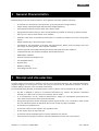
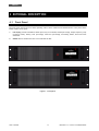
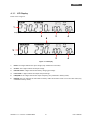
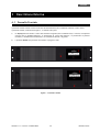
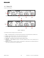
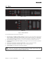
Uninterruptible Power Supply
EXA
EXA
EXA
EXA
EXA
1.1
1.5
2.2
2.6
3.2
Rack Mount
Rack Mount
Rack Mount
Rack Mount
Rack Mount
User’s manual
Manuale utente
Index
Safety Warnings ................................................................................ 1
1 Introduction ................................................................................. 2
2 General Characteristics ................................................................... 3
3 Receipt and site selection ................................................................ 3
4 EXTERNAL DESCRIPTION .................................................................. 4
4.1
Front Panel ............................................................................. 4
4.1.1
4.2
LCD Display .................................................................................5
Rear Side................................................................................ 6
5 Electrical Installation and First Start Up ............................................... 7
6 Functioning ................................................................................. 8
6.1
6.2
6.3
6.4
6.5
Normal Mode ........................................................................... 8
Battery Mode ........................................................................... 8
Low Battery and Automatic Restart ................................................. 8
Load Control............................................................................ 9
Fault Condition ........................................................................ 9
7 Communication Interfaces ............................................................... 9
8 Technical Characteristics ................................................................ 10
9 Maintenance ............................................................................... 11
9.1
9.2
9.3
UPS Cleaning ......................................................................... 11
Battery ................................................................................ 11
Operator Safety ...................................................................... 11
10 Troubleshooting ........................................................................... 12
Conformity to the European Directives ................................................... 13
Product Disposal ............................................................................... 13
Lead Batteries ................................................................................. 13
© Copyright 2012 TECNOWARE s.r.l. All rights reserved.
All trademarks are property of their respective owners.
TECNOWARE s.r.l.
Via Montetrini, 2E – Molino del Piano – Florence – Italy
www.tecnoware.com
Edition: January 2012 – version: 1.0
No part of this manual may be reproduced, even partially, without the
authorisation of TECNOWARE s.r.l.
TECNOWARE s.r.l. reserves the right to change specifications at any time
and without notice.
Indice
Avvisi di Sicurezza ............................................................................ 14
1 Introduzione ............................................................................... 15
2 Caratteristiche Generali ................................................................. 15
3 Ricevimento e Collocazione ............................................................. 16
4 Descrizione Esterna ....................................................................... 17
4.1
Pannello Frontale .................................................................... 17
4.1.1
4.2
Display LCD ............................................................................... 18
Retro................................................................................... 19
5 Installazione e Prima Accensione ...................................................... 20
6 Funzionamento ............................................................................ 21
6.1
6.2
6.3
6.4
6.5
Modo Normale ........................................................................ 21
Modo Batteria ........................................................................ 21
Fine Autonomia e Riaccensione Automatica ..................................... 21
Controllo del Carico ................................................................. 21
Segnalazioni di Guasto .............................................................. 22
7 Interfacce di Comunicazione ............................................................ 22
8 Caratteristiche Tecniche................................................................. 23
9 Manutenzione .............................................................................. 24
9.1
9.2
9.3
Pulizia dell’UPS ...................................................................... 24
Batterie ............................................................................... 24
Sicurezza dell’Operatore ........................................................... 24
10 Anomalie ed Interventi ................................................................... 25
Conformità alle Direttive Europee ......................................................... 26
Smaltimento del Prodotto ................................................................... 26
Batterie al Piombo ............................................................................ 26
ENGLISH
User’s Manual - English
Safety Warnings
Read this manual carefully and completely before installing and using the TECNOWARE EXA Rack
Mount Uninterruptible Power Supply, which, from here after, will also be referred to as UPS.
This manual should be kept close to the UPS and read before the UPS is installed and used.
The UPS must be used only by properly trained personnel. To ensure correct and safe
operations, it is necessary that operators and maintenance personnel observe the general
safety Standards as well as the specific instructions included in this manual.
Risk of electric shock: do not remove the cover. The UPS contains internal parts, which are at a
high Voltage and are potentially dangerous, capable of causing injury or death by electric
shock.
There are no internal parts in the UPS, which are user serviceable. Any repair or maintenance
work must be performed exclusively by qualified technical personnel authorized by
TECNOWARE. TECNOWARE declines any responsibility if this warning is disregarded.
Warning to the technical personnel authorized for Service: since internal components are
connected to the batteries, they will remain powered, and therefore dangerous, even after the
UPS has been disconnected from AC power mains. Before any repair or maintenance work,
disconnect the batteries, by removing the positive cable (red colour) from the positive pole of
the battery.
It is compulsory to ground the UPS according to Safety Standards. The AC mains power supply
socket used to power the UPS must have an earth connection.
In the event of AC main power supply failure (when the UPS works in Battery mode), do not
unplug the power supply cable to the UPS to ensure earth continuity to the connected loads.
Since the AC mains power supply cable acts as a separation device, the AC mains power socket
used to supply the UPS and/or the rear side of the UPS must be accessible to easily disconnect
the cable in case of dangerous conditions.
Risk of electric shock at the Output lines when the UPS is ON.
Risk of electric shock at the Output lines while the unit is connected to the AC utility line.
Do not obstruct ventilation slots or holes and do not rest any object on top of the UPS.
Do not insert objects or pour liquids in the ventilation holes.
Install the UPS indoors, in a protected, clean and moisture-free environment.
Do not expose to the direct sun light.
Do not keep liquids, flammable gases or corrosive substances near the UPS.
UPS EXA 1.1-1.5-2.2-2.6-3.2 Rack Mount
1
User’s manual
ENGLISH
1 Introduction
EXA Rack Mount is a Line Interactive Pure Sinewave UPS (Uninterruptible Power Supply) specifically designed to
protect your computer from any type of irregularities in the AC line (such as black-outs, under or over voltages,
micro-interruptions), which often cause damage to your Hardware and Software.
Under normal AC line condition, EXA Rack Mount performs output voltage regulation and filters frequently
occurring electrical disturbances (such as transients, spikes, interferences, etc.), this protecting all devices
connected to the outlets, and recharging the batteries in an ideal way. In case of anomaly to the AC line, the UPS
continues feeding the protected equipment.
EXA Rack Mount is equipped with a RS-232 or USB interface which can be used to notify a power failure or a low
battery condition directly to a computer: this makes it possible to automatically save your data during an
extended black-out with the most widespread operating systems (Windows, Linux, etc.).
Read this manual carefully before using the EXA Rack Mount; it includes important
safety warnings and useful advices for correct use and installation.
This manual is a guide that enables you to correctly install and use your EXA Rack
Mount. This manual includes important SAFETY instructions for the operator, for the
UPS correct installation, and gives useful advice on the product and battery
maintenance. For any type of problem, please refer to this manual before calling the
customer service.
EXA Rack Mount is constantly being developed and improved: consequently, your unit may differ somewhat from
the description contained in this manual.
This manual includes the following models:
• EXA 1.1 Rack Mount (1.1 KVA)
• EXA 1.5 Rack Mount (1.5 KVA)
• EXA 2.2 Rack Mount (2.2 KVA)
• EXA 2.6 Rack Mount (2.6 KVA)
• EXA 3.2 Rack Mount (3.2 KVA)
In this manual EXA Rack Mount will simply be referred to as UPS.
User’s manual
2
UPS EXA 1.1-1.5-2.2-2.6-3.2 Rack Mount
ENGLISH
2 General Characteristics
EXA Rack Mount has all the advanced features, which guarantee maximum reliability and safety:
•
All functions are controlled by a microprocessor, giving full guarantee of high reliability.
•
Output Voltage regulation through AVR (Automatic Voltage Regulation).
•
Overload protection both in normal mode and in battery mode.
•
High performance battery charger, which extends the battery medium life ensuring an optimal recharge.
•
Start up even if the electrical network is not available.
•
Automatic restart after an automatic shut down due to a low battery condition once the AC utility power
returns.
•
Adapts automatically to 50 or 60 Hz input frequency.
•
LCD display for the visualization of the Input and Output Voltage, Battery Level percentage, Load Level
percentage, functioning modes, alarm and fault conditions.
•
Acoustic signals of various kinds indicating functioning modes and alarm/fault condition.
•
Communication with the computer through RS-232 and USB interfaces.
•
SNMP Adapter (optional).
•
Protects and filters the telephone line.
•
Fast swappable battery.
•
High efficiency
•
Maximum reliability
•
Smart design and easy to use
3 Receipt and site selection
Carefully remove the UPS from its packaging, and carry out a meticulous inspection. We recommend keeping the
original packaging in a secure place, in case you need to send the UPS for maintenance purposes. In case of
transport damage, notify the carrier and dealer immediately.
We recommend paying attention to the below points in order to choose a correct placement for your UPS:
•
The UPS is designed to operate in a protected environment (e.g. offices). We therefore recommend
installing it in a place with very little or no humidity, dust or smoke.
•
In all circumstances, see the “Technical Characteristics” chapter for environmental specifications and
check that the selected area meets these specifications.
•
During normal operation the UPS discharges a minimal amount of heat. So it is necessary to leave at least
20 cm of unobstructed space all around the UPS in order to keep it properly ventilated.
•
Do not obstruct ventilation holes.
•
Do not insert objects or pour liquids in the ventilation holes.
•
Do not rest any object on top of the UPS.
•
Do not keep liquids, flammable gases or corrosive substances near the unit.
•
Install the UPS on a properly tiled floor. Avoid the installation on a floor that is not tiled flat.
UPS EXA 1.1-1.5-2.2-2.6-3.2 Rack Mount
3
User’s manual
ENGLISH
4 EXTERNAL DESCRIPTION
4.1
Front Panel
The front panel informs the user about operating status, alarm conditions and measurements. Front panel shown
below consists of two parts:
1.
LCD display provides information about input (only in line mode) and output voltage, output frequency (only
in battery mode), battery level percentage, load level percentage, functioning modes, alarm and fault
conditions.
2.
ON/OFF button: enables the user to turn ON/OFF the UPS.
1
2
1
2
Figure 1 – Front panel
User’s manual
4
UPS EXA 1.1-1.5-2.2-2.6-3.2 Rack Mount
ENGLISH
4.1.1 LCD Display
Please refer to figure 2.
1
Display visualizzato in modalità rete
2
6
3
4
3
4
5
Display visualizzato in modalità batteria
Figure 2 –LCD Display
1.
INPUT: the 3 digits indicate the input voltage (only visualized in line mode).
2.
OUTPUT: the 3 digits indicate the output voltage.
3.
BATTERY LEVEL: 3 digits indicate the battery charging percentage.
4.
LOAD LEVEL: 3 digits indicate the output load percentage.
5.
FREQUENCY: the 3 digits indicate the output frequency (only visualized in battery mode).
6.
BUZZER: this icon indicates the UPS works in battery mode and acoustic alarm in on in the same time (only
visualized in battery mode).
UPS EXA 1.1-1.5-2.2-2.6-3.2 Rack Mount
5
User’s manual
ENGLISH
4.2
Rear Side
5
6
3
4
1
2
EXA 1.1-1.5-2.2
3
6
5
1
4
2
2
EXA 2.6-3.2
Figure 3 – Rear Side
1.
Grounded AC Input power socket with input fuse: IEC C14 type; to connect the UPS to the AC utility line.
Fuse electrical specification: max current 6A (EXA 1.1–1.5 Rack Mount), max current 8A (EXA 2.2 Rack Mount)
or max current 10A (EXA 2.6-3.2 Rack Mount), voltage 250 V.
2.
Grounded UPS Output receptacles: IEC C13 type, black colour, to supply critical loads.
3.
Telephone protection (RJ11 IN/OUT connectors): to protect and filter a phone line (TNV-3 type
connections).
4.
Computer Interface (DB9 female connector): it is the communication RS-232 port.
5.
Computer Interface (USB connector): it is the communication USB port.
6.
ON/OFF button: to active the AC utility line.
In case of anomaly to the AC line (black-out), ONLY the UPS Output receptacles (black
colour, #2) continue supplying the correct power to all connected equipment. Please
connect all the non-critical devices to the UPS Output receptacles.
User’s manual
6
UPS EXA 1.1-1.5-2.2-2.6-3.2 Rack Mount
ENGLISH
5
Electrical Installation and First Start Up
We advise you to follow the steps below explained for greater safety:
1.
Switch off all the devices (Personal Computer or other electronic devices) that need to be supplied by the
UPS.
2.
Connect the UPS Input socket to the AC line outlet through the supplying input cable. It is mandatory to
ground the AC line outlet according to the Safety Standards. Carefully check the grounding, make sure that
the utility power is available, and that its range falls within the UPS specifications (refer to the
“Specifications” chapter).
3.
Switch ON the ON/OFF button on the rear panel and then press the ON/OFF button on the front panel for 3
seconds: the UPS emits a brief acoustic signal, turns the LCD display on, and performs a functioning SELFTEST. Leave the UPS in Normal mode for at least 4 hours in order to completely recharge the batteries.
4.
Switch the UPS off (by pressing again the ON/OFF button for 3 seconds and putting the switch in the rear side
in OFF position).
5.
Connect the devices to be supplied to the UPS outputs, by using only the included cables. Be sure all the
devices have the main switch in ON position.
6.
Turn on the UPS again. Check that it starts working correctly and it doesn’t signal any sort of anomaly.
Moreover be sure that all the devices connected to the UPS outputs are working correctly. By LCD display
check if the Output load percentage is less than 100%; otherwise it is necessary to remove part of the Output
load.
7.
Simulate a black-out by removing the AC Input line. The UPS starts working in Battery mode. Moreover the
UPS emits a brief acoustic signal every 10 seconds.
8.
Be sure that all the devices connected to the UPS outputs are working correctly and the UPS doesn’t signal
any sort of anomaly.
9.
Restore the AC Input line: after few seconds the UPS turns back in Normal mode.
Before using EXA Rack Mount normally, leave it in Normal mode in order to charge the batteries completely as
specified at point 3. The batteries reach the 90% of their capacity after about 4 hours of recharge.
It is compulsory to ground/earth the UPS according to the Safety Standards.
Risk of electric shock at the Output lines if the UPS is ON, even when the UPS is not
connected to AC utility line.
Risk of electric shock at the Output lines while the unit is connected to the AC utility
line.
Risk of electric shock: do not remove the cover. The UPS contains internal parts, which
are at a high Voltage and are potentially dangerous, capable of causing injury or death
by electric shock.
There are no internal parts in the UPS that are user serviceable. Any repair or
maintenance work must be performed exclusively by qualified technical personnel
authorized by TECNOWARE. TECNOWARE declines any responsibility if this warning is
disregarded.
Disregard for these warnings may lead to a risk of electric shock to operators.
UPS EXA 1.1-1.5-2.2-2.6-3.2 Rack Mount
7
User’s manual
ENGLISH
6 Functioning
6.1
Normal Mode
The UPS typically works in Normal mode: Input mains power is available and its amplitude is within specifications.
During Normal mode, the UPS recharges the batteries and keeps them in an optimal charging voltage.
6.2
Battery Mode
The UPS automatically runs in Battery mode if the AC Input Line voltage amplitude gets out of security limits (in
case of a black-out or over-voltage/low-voltage): in this case, the UPS supplies the required output power by its
internal battery and by the Inverter block.
The UPS automatically returns in Normal mode a few seconds after the AC Input Line is recovered.
The Battery mode is identified by an acoustic signal every 10 seconds.
6.3
Low Battery and Automatic Restart
In Battery mode, EXA Rack Mount indicates the Low Battery condition whenever the battery reaches a charge
level allowing connected devices to operate for approximately one more minute.
The UPS warns operators of Low Battery by emitting an acoustic signal every second.
If AC Input does not come back on within few minutes, the UPS shuts-down automatically thus preventing the
batteries from discharging excessively; the UPS stops supplying Output power, deactivates control panel indication
and goes to a waiting state. Once AC Input comes back on, the UPS restarts automatically and after some seconds
it goes back to work in Normal mode.
After a complete discharge, the UPS needs 4 hours to recharge completely the batteries. The UPS recharges
batteries automatically if it works in Normal mode or if it is off and connected to the AC Input Line.
User’s manual
8
UPS EXA 1.1-1.5-2.2-2.6-3.2 Rack Mount
ENGLISH
6.4
Load Control
The UPS indicates the Output Load level by LCD display (as described in the chapter 4).
When the Output load is higher than nominal value the UPS warns of Overload condition by LCD display, by
emitting a continuous acoustic alarm.
The UPS warns of an Overload less than 110% by acoustic alarm.
An Overload between 110% and 130% is accepted for about 30 seconds and after UPS switches automatically off.
The UPS switches immediately off if the Overload is higher than than 130%.
Once the requested power is back within range, the UPS switches automatically to the Normal mode.
Make sure that the UPS never indicates Overload condition.
Do not connect a load greater than rated value to the UPS (see POWER specifications in
the chapter “Technical Characteristics”), as this may damage the unit. In this case the
warranty is void.
6.5
Fault Condition
The UPS indicates the Fault condition by LCD display, by emitting a continuous acoustic alarm.
During Fault condition, the UPS doesn’t supply Output power and so all the supplied devices are switched off.
7
Communication Interfaces
The UPS is factory-equipped with RS232 and USB Communication Interfaces. On the UPS rear side there are the
connectors of the Interfaces.
Only one of the RS232/USB communications can be activated at one time. To activate RS232 communication it is
sufficient to connect the RS232 cable only; to activate USB communication it is sufficient to connect the USB cable
only.
The RS232 and USB signals are all isolated through photo-couplers from the dangerous voltages that are
present inside the UPS.
Connecting to the Web site www.tecnoware.com, it is possible to download, free of charge, the update UPS
management Software, compatible with the most popular Operative Systems
.
UPS EXA 1.1-1.5-2.2-2.6-3.2 Rack Mount
9
User’s manual
ENGLISH
8
Technical Characteristics
UPS EXA Rack Mount Model
Power
1.1
1.5
2.2
2.6
3.2
1100 VA
1500 VA
2200 VA
2600 VA
3200 VA
(550 W)
(750 W)
(1100 W)
(1300 W)
(1600 W)
Technology
Line Interactive Pure Sinewave with Stabilizer
Nominal Input Voltage
Single-phase 230 Vac
Input Voltage Range
+20% / -25%
Input/Output Frequency
50/60 Hz (automatic selection)
Input Frequency Range
+/- 10%
Nominal Output Voltage
Single-phase 230 Vac
Output Voltage Regulation
(Normal mode)
Through AVR (Automatic Voltage Regulation)
Output Voltage Regulation
(Battery mode)
+/- 5%
Output Inverter Waveform
Sinewave
Accepted Overload
110%-60sec / 120%-30sec / >120%-20msec
CE
Certifications
Standards: CEI EN 62040-1: 2008 (Low Voltage Directive) –
CEI EN 62040-2: 2006 (EMC Directive)
Efficiency
96%
Battery Type
Lead acid, sealed, free maintenance
Number of batteries
2
3
24 Vdc
36 Vdc
Nominal Battery Voltage
Battery Specifications
12 Vdc – 7 Ah
6 cells
12 Vdc – 7 Ah
6 cells
12 Vdc – 8 Ah
6 cells
12 Vdc – 8 Ah
6 cells
12 Vdc – 8 Ah
6 cells
Backup Time (typical)
12 min
10 min
8 min
8 min
6 min
Battery Charge Time (typical)
4 hours
Audible Noise (at 1 meter)
Environmental Operative Specification
< 45 dBA
Temperature: 0-40 °C - Humidity 0-95% (without condensation)
Altitude: max 3.000 mt
Computer Interface
1 RS232 port and 1 USB port
Included Software UPSilon 2000,
downloadable free of charge from www.tecnoware.com
UPS Management Software
SNMP Interface
Optional
Telephone and Modem protection
Output sockets
RJ11 plugs included
4 UPS Output sockets (IEC type)
6 UPS Output sockets (IEC type)
Dimension (W x H x D)
30,9 x 8,8 x 43,8 cm (2U)
36 x 13,2 x 43,8 cm (3U)
Net Weight
14,5 Kg
15,5 Kg
16,5 Kg
18,5 Kg
19.5 Kg
Technical data may change without prior notice
User’s manual
10
UPS EXA 1.1-1.5-2.2-2.6-3.2 Rack Mount
ENGLISH
9
9.1
Maintenance
UPS Cleaning
Before starting any cleaning operation, be sure that:
1. The AC Input Voltage for the UPS has been removed.
2. The UPS is OFF.
Use only a cloth dampened with water to clean the unit.
If UPS works in an environmental unusually dusty or dirty, remove the dirty from the ventilation holes.
Before restarting the UPS be sure it is completely dry. If any liquid gets inside the UPS, do not start the unit and
contact Technical Service immediately.
9.2
Battery
If the UPS is NOT going to be used for a long period of time, ensure that the batteries are left fully charged.
If the UPS has not been used for more than three months, go through the “First Start Up” procedure described in
the chapter 5 before using it again.
Please keep in mind that the batteries must be recharged at least once a month. Take in mind that batteries are
recharged automatically if the UPS works in Normal mode or if the UPS is off and connected to the AC Input Line.
Battery life strongly depends on the ambient temperature. There are also other factors like the number of chargedischarge cycles, the discharge depth, humidity and altitude.
The recommended environmental specifications for a correct use of batteries are listed in the “Technical
Specifications” section.
9.3
Operator Safety
Whenever the UPS is not responding anymore to original characteristics, the UPS must be made non-operative and
every usage not authorised must be avoided. After it will be necessary to refer to qualified technical personnel.
Original safety characteristics might not be if, for example, the UPS has visible damage or irregular operation.
UPS EXA 1.1-1.5-2.2-2.6-3.2 Rack Mount
11
User’s manual
ENGLISH
10 Troubleshooting
Alarms and problems you may encounter during operating the UPS are given in the table below. Apply
the suggestions corresponding to each anomaly as described into the table.
If your anomaly is excluded or the suggested actions do not solve your problem, consult the Technical Service.
Please give the following information to the Technical Service:
Model and serial number of the UPS, which can be found on the nameplate on the rear of the UPS.
Description of anomaly.
Risk of electric shock: do not remove the cover. The UPS contains internal parts that are
at a high Voltage and are potentially dangerous, capable of causing injury or death by
electric shock.
There are no internal parts in the UPS that are user serviceable. Any repair or
maintenance work must be performed exclusively by qualified technical personnel
authorized by TECNOWARE.
TECNOWARE declines any responsibility if this warning is disregarded.
Warning to the technical personnel authorized for service: since internal components
are connected to the batteries, they will remain powered, and therefore dangerous,
even after the UPS has been disconnected from AC power mains. Before any repair or
maintenance work, disconnect the batteries, by removing the positive cable (red colour)
from the positive pole of the battery.
ANOMALY
POSSIBLE CAUSE
The UPS does not
turn on
ON/OFF button
Press the ON/OFF button.
Batteries are flat
Recharge the batteries for at least 4 hours.
Electronic board failure
Refer to Technical Service.
Input mains power cable is
disconnected.
Check the input mains power cable.
Check the presence of the electrical mains.
The UPS always
function in Battery
mode
ACTION TO SOLVE
ON/OFF switch
Check if the rear ON/OFF switch is in ON position
Input mains fuse is burnt
Replace the fuse with another of the same type.
Black-out conditions / surge/
Wait until the AC Input Line returns to normal conditions.
Over-Voltage or Low-Voltage
Electronic board failure
Refer to Technical Service.
Battery Autonomy is Battery is not fully charged.
too short
Electronic board failure
Recharge the battery for at least 6 hours.
“OVERLOAD” alarm
“OVERLOAD” condition
Disconnect all devices that cause the overload condition.
“FAULT” alarm
“FAULT” condition
Check if UPS is in OVERLOAD condition.
Refer to Technical Service.
The UPS Management
Software sends a
communication error
Check that the USB (or RS232) cable is correctly connected
between the UPS and the Computer.
The Software is not correctly
installed
Install correctly the specific Software for your Computer’s
Operative System.
The UPS does not
communicate with
the Computer
Refer to Technical Service.
If the described anomalies should continue despite the advised troubleshooting, or should they
manifest in any other form, please contact:
TECNOWARE SERVICE
www.tecnoware.com
User’s manual
12
UPS EXA 1.1-1.5-2.2-2.6-3.2 Rack Mount
ENGLISH
Conformity to the European Directives
TECNOWARE S.r.l. confirms that EXA Rack Mount models comply with the requirements set out in: the Low Voltage Directive
(Safety) 2006/95/EC and following amendments, the EMC (Electro-Magnetic Compatibility) Directive 2004/108/EC and
following amendments.
The following standards were applied:
Low Voltage Directive (Safety): CEI EN 62040-1: 2008
EMC Directive (Electro-Magnetic Compatibility): CEI EN 62040-2: 2006
Product Disposal
UPS EXA Rack Mount cannot be disposed as an urban waste, but must be treated as a separate waste.
Any violation is indictable with financial sanctions as per in force regulations.
An incorrect waste disposal or an improper use of the same or of any parts can be damaging for the
environment and for human health.
A correct waste disposal of products having the dustbin symbol marked by a cross help to avoid
negative consequences to the environment and to human health.
Lead Batteries
EXA Rack Mount models contain lead acid, sealed, maintenance free batteries.
The batteries cannot be disposed as an urban waste, but must be treated in conformity with
2006/66/CE European Directive; any violation is indictable with financial sanctions as established into
2006/66/CE European Directive.
UPS EXA 1.1-1.5-2.2-2.6-3.2 Rack Mount
13
User’s manual
ITALIANO
Manuale Utente – Italiano
Avvisi di Sicurezza
Leggere attentamente e completamente questo manuale prima di installare ed utilizzare il
gruppo di continuità TECNOWARE della serie EXA Rack Mount, che in seguito verrà chiamato
anche semplicemente UPS.
Conservare con cura questo manuale vicino all’UPS e consultarlo sempre prima di operare sullo
stesso.
L'UPS deve essere utilizzato solo da personale opportunamente istruito. Per l’uso corretto e in
condizioni di sicurezza è necessario che gli operatori ed il personale di manutenzione si
attengano alle norme generali di sicurezza, in aggiunta alle norme specifiche contenute in
questo manuale.
Rischio di shock elettrico: non rimuovere il coperchio. L’UPS presenta parti interne sotto
tensione che sono potenzialmente pericolose e possono provocare lesioni o morte per shock
elettrico.
L’UPS non ha parti interne soggette a manutenzione da parte dell’utente. Interventi tecnici di
qualsiasi tipo devono essere compiuti solo da personale tecnico specializzato ed autorizzato da
TECNOWARE. In caso contrario TECNOWARE declina ogni sua responsabilità.
Avviso per il personale tecnico autorizzato alla manutenzione: anche dopo aver spento l’UPS e
scollegato dalla rete elettrica, le parti interne sono ancora in tensione, essendo collegate alle
batterie, e quindi pericolose. Prima di effettuare qualsiasi tipo di riparazione o manutenzione,
scollegare le batterie, staccando il cavo positivo (di colore rosso) dal polo positivo della batteria
a cui è collegato.
Il collegamento a terra dell’UPS secondo le norme vigenti è obbligatorio. La presa di Rete
Elettrica a cui è collegato l’UPS deve essere dotata di connessione a terra.
In caso di assenza della Rete Elettrica (cioè durante il funzionamento in modo Batteria), non
staccare il cavo di alimentazione. In caso contrario non è garantita la continuità di terra alle
utenze collegate.
Il cavo di alimentazione dell’UPS ha le funzioni di dispositivo di sezionamento. Per questo
motivo la presa di Rete Elettrica a cui l’UPS è collegato e/o il retro dell’UPS devono essere
facilmente accessibili per disconnettere facilmente il cavo di alimentazione in caso di pericolo.
Rischio di shock elettrico in Uscita se l’UPS è acceso.
Rischio di shock elettrico in Uscita se è presente la Tensione di Rete elettrica in Ingresso.
Non ostruire le fessure o i fori di ventilazione e non appoggiare alcun oggetto sopra l’UPS. Non
inserire oggetti o versare liquidi nei fori di ventilazione.
Installare l’UPS in ambiente chiuso, pulito e privo di umidità. Non esporre l’UPS alla luce diretta
del sole. Non avvicinare liquidi, gas infiammabili o sostanze corrosive.
Manuale utente
14
UPS EXA 1.1-1.5-2.2-2.6-3.2 Rack Mount
ITALIANO
1 Introduzione
EXA Rack Mount è un UPS (Uninterruptible Power Supply), cioè un gruppo di continuità, di tipo Line Interactive ad
Onda Sinusoidale, realizzato appositamente per proteggere il Computer da qualsiasi avaria della rete elettrica
(black-out, sottotensioni, sovratensioni, microinterruzioni), causa dei frequenti danneggiamenti di Hardware e
Software.
Quando è presente la tensione di rete elettrica, EXA Rack Mount svolge le funzioni di stabilizzatore e filtra i
disturbi frequentemente presenti sulla linea elettrica (transienti, spike, interferenze, etc.), preservando in tal
modo i dispositivi collegati alla sua uscita; inoltre ricarica le batterie in modo ottimale. In caso di avaria della rete
elettrica, l’UPS continua ad alimentare le apparecchiature protette.
EXA Rack Mount è dotato di un’interfaccia RS-232 o USB che può essere utilizzata per segnalare ad un generico
elaboratore o computer le condizioni di assenza rete e di fine autonomia: ciò rende possibile lo svolgimento delle
funzioni di salvataggio automatico dei dati durante un black-out prolungato con i più diffusi sistemi operativi
(Windows, Linux, etc.).
Leggere attentamente questo manuale prima di utilizzare EXA Rack Mount perché
contiene importanti avvisi di sicurezza per l’operatore ed utili consigli per un corretto
impiego.
Questo manuale è una guida per installare e utilizzare correttamente l’UPS. Nel manuale
sono incluse importanti istruzioni di SICUREZZA per l’operatore e per una corretta
installazione dell’UPS e utili consigli per la manutenzione del prodotto e delle batterie.
Per ogni problema fare prima riferimento al manuale e poi rivolgersi al Servizio
Assistenza.
EXA Rack Mount è soggetto a continui sviluppi e migliorie: di conseguenza può differire lievemente, in alcuni
dettagli, da quanto descritto nel presente manuale.
Questo manuale è relativo ai seguenti modelli:
• EXA 1.1 Rack Mount (1.1 KVA)
• EXA 1.5 Rack Mount (1.5 KVA)
• EXA 2.2 Rack Mount (2.2 KVA)
• EXA 2.6 Rack Mount (2.6 KVA)
• EXA 3.2 Rack Mount (3.2 KVA)
In questo manuale EXA Rack Mount sarà chiamato anche semplicemente UPS.
2 Caratteristiche Generali
EXA Rack Mount presenta tutte le moderne caratteristiche che garantiscono massima affidabilità e sicurezza:
•
Controllo a microprocessore di tutte le funzioni, garanzia di alta affidabilità.
•
Stabilizzazione in uscita tramite AVR (Automatic Voltage Regulation).
•
Protezione da sovraccarico sia nel modo di funzionamento normale che in modo batterie.
•
Carica batterie di alte prestazioni che prolunga il tempo medio di vita delle batterie e ne garantisce una
ricarica ottimale.
•
Accensione anche in condizioni di rete elettrica assente.
UPS EXA 1.1-1.5-2.2-2.6-3.2 Rack Mount
15
Manuale utente
ITALIANO
•
Riaccensione automatica dopo lo spegnimento per fine autonomia al ritorno della tensione di rete.
•
Adattabilità automatica alla frequenza d’ingresso 50 o 60 Hz.
•
Display LCD per visualizzare il valore della Tensione d’Ingresso e d’Uscita, la percentuale di carica delle
batterie, la percentuale di potenza utilizzata, le modalità di funzionamento e le condizioni di allarme e
guasto.
•
Segnalazioni acustiche di vario tipo durante il normale funzionamento e che evidenziano le eventuali
condizioni di allarme.
•
Comunicazione con il computer tramite porta di comunicazione RS-232 o USB.
•
Adattatore SNMP (opzionale).
•
Protezione e filtro della linea telefonica.
•
Rapida sostituzione delle batterie.
•
Alta affidabilità.
•
Elevato rendimento e basso costo d’esercizio.
•
Dimensioni compatte.
•
Curato design.
•
Semplicità d’uso.
3 Ricevimento e Collocazione
Al ricevimento dell’UPS, si consiglia di togliere subito l’imballo e di controllare lo stato dell’UPS. In caso di danni
dovuti al trasporto, annotarli sulla bolla di accompagnamento merce e contattare subito il fornitore.
Si consiglia di conservare l’imballo originale in luogo sicuro nell’eventualità futura che l’UPS dovesse essere
spedito per la manutenzione.
Si consiglia di prestare attenzione ai punti seguenti per la scelta di una corretta collocazione dell’UPS:
•
L’UPS è progettato per operare in ambienti chiusi (come ad esempio gli uffici). Si consiglia perciò
d’installarlo in un luogo privo di umidità, polvere e fumo eccessivi.
•
Consultare comunque il capitolo “Caratteristiche Tecniche” per i requisiti ambientali e controllare che il
luogo scelto rientri in tali specifiche.
•
Durante il normale funzionamento l’UPS emette una quantità minima di calore. È perciò necessario
lasciare uno spazio libero di almeno 20 cm sia lateralmente che sul retro dell’UPS per permetterne una
sufficiente areazione.
•
Non ostruire le fessure o i fori di ventilazione.
•
Non inserire oggetti o versare liquidi nei fori di ventilazione.
•
Non appoggiare alcun oggetto sopra l’UPS.
•
Non avvicinare liquidi, gas infiammabili o sostanze corrosive.
•
Installare l’UPS su superfici piane non inclinate.
Manuale utente
16
UPS EXA 1.1-1.5-2.2-2.6-3.2 Rack Mount
ITALIANO
4 Descrizione Esterna
4.1
Pannello Frontale
Il pannello frontale informa l’utente sullo stato di funzionamento, sulle condizioni di allarme e sulle misure.
Il pannello frontale, mostrato nella figura 1, è costituito da 2 parti:
1.
Un display LCD che fornisce i valori della tensione d’ingresso (solo in modalità rete) e d’uscita, la frequenza
d’uscita (solo in modalità batteria), la percentuale di carica delle batterie, la percentuale di potenza
utilizzata, le modalità di funzionamento e le condizioni di allarme e di guasto.
2.
Il pulsante ON/OFF che permette di accendere e spegnere l’UPS.
1
2
1
2
Figura 1 – Pannello Frontale
UPS EXA 1.1-1.5-2.2-2.6-3.2 Rack Mount
17
Manuale utente
ITALIANO
4.1.1 Display LCD
Prego riferirsi alla figura 2.
1
Display visualizzato in modalità rete
2
6
3
4
3
4
5
Display visualizzato in modalità batteria
Figura 2 – Display LCD
Le informazioni indicate dal display LCD sono elencate sotto:
1.
INPUT: i 3 digit INPUT indicano il valore della tensione d’ingresso in volt (visualizzato solo in modalità rete).
2.
OUTPUT: i 3 digit OUTPUT indicano il valore della tensione d’uscita in volt.
3.
BATTERY LEVEL: i 3 digit indicano la percentuale di carica delle batterie.
4.
LOAD LEVEL: i 3 digit indicano la percentuale di potenza erogata in uscita.
5.
FREQUENCY: i 3 digit FREQUENCY indicano il valore della frequenza d’uscita in hertz (visualizzato solo in
modalità batteria).
6.
BUZZER: questo simbolo è acceso per indicare il funzionamento in modalità batteria contemporaneamente al
suono acustico (visualizzato solo in modalità batteria).
Manuale utente
18
UPS EXA 1.1-1.5-2.2-2.6-3.2 Rack Mount
ITALIANO
4.2
Retro
5
6
3
4
1
2
EXA 1.1-1.5-2.2
3
6
5
1
4
2
2
EXA 2.6-3.2
Figura 3 – Pannello Posteriore
Sul retro di EXA Rack Mount sono presenti (vedi figura 3):
1.
Presa d’Ingresso con TERRA con fusibile d’ingresso: di tipo IEC C14. Serve per collegare l’UPS alla linea
elettrica d’Ingresso. Caratteristiche elettriche fusibile: corrente massima 6A (EXA 1.1–1.5 Rack Mount),
corrente massima 8A (EXA 2.2 Rack Mount) o corrente massima 10A (EXA 2.6-3.2 Rack Mount), tensione 250 V.
2.
Prese d’Uscita UPS con TERRA: di tipo IEC C13, colore nero, da utilizzare per alimentare carichi critici.
3.
Protezione Telefonica (connettori RJ11 IN/OUT): per proteggere e filtrare una linea telefonica (connessioni
di tipo TNV-3).
4.
Interfaccia di Comunicazione (connettore femmina DB9): è la porta di comunicazione RS232.
5.
Interfaccia di Comunicazione (connettore USB): è la porta di comunicazione USB.
6.
Pulsante ON/OFF: serve ad attivare la linea elettrica d’ingresso.
In caso di assenza della rete elettrica (black-out) SOLO le prese d’Uscita UPS (#2), di
colore nero, continuano a fornire potenza ai dispositivi collegati. Quindi utilizzare SOLO
le prese d’Uscita UPS per alimentare i dispositivi critici.
UPS EXA 1.1-1.5-2.2-2.6-3.2 Rack Mount
19
Manuale utente
ITALIANO
5 Installazione e Prima Accensione
La procedura è molto semplice. Si consiglia di seguire con attenzione i punti successivi per una maggiore sicurezza.
1.
Spegnere i dispositivi (Personal Computer o altre apparecchiature elettroniche) che devono essere alimentati
tramite l’UPS.
2.
Utilizzare il cavo di alimentazione a corredo per collegare l’UPS ad una presa di alimentazione elettrica. La
presa di alimentazione scelta deve avere obbligatoriamente una connessione a terra secondo le norme
vigenti. Verificare il collegamento a terra della presa e accertarsi della presenza della tensione di rete
elettrica e che la sua ampiezza rientri nelle specifiche (vedi capitolo “Caratteristiche Tecniche”).
3.
Portare l’interruttore posteriore in posizione ON successivamente premere per 3 secondi il pulsante ON/OFF
del pannello frontale: l’UPS illumina il display LCD, emette una segnalazione acustica e svolge un Self Test di
funzionamento. Lasciare l’UPS acceso per almeno 4 ore al fine di ricaricare completamente le batterie.
4.
Spengere l’UPS (premendo di nuovo il pulsante ON/OFF del pannello frontale per 3 secondi e ponendo su
OFF l’interruttore posteriore).
5.
Collegare i vari dispositivi alle prese d’uscita dell’UPS tramite i cavi in dotazione; posizionare i relativi
interruttori su ACCESO.
6.
Riaccendere l’UPS; controllare lo svolgimento della fase di accensione e che l’UPS non segnali nessuna
anomalia. Accertarsi che tutti i dispositivi si siano accesi regolarmente. Inoltre controllare la percentuale di
carico in Uscita indicata sul display LCD e assicurandosi che il valore sia inferiore al 100%, altrimenti è
necessario rimuovere parte del carico in Uscita.
7.
Simulare un black-out, togliendo la Tensione di Rete elettrica in Ingresso. L’UPS passa a funzionare nel modo
Batteria. Inoltre ogni 10 secondi emette un breve segnale acustico di allarme, che indica il funzionamento in
modo Batteria.
8.
Accertarsi che tutti i dispositivi alimentati dall’UPS stiano continuando a funzionare correttamente e che
l’UPS non segnali nessuna anomalia.
9.
Ripristinare la Tensione di Rete elettrica in Ingresso; dopo alcuni secondi, l’UPS ritorna nel modo Normale.
Prima di poter utilizzare normalmente EXA Rack Mount, si consiglia di lasciarlo acceso in modo Normale per
caricare le batterie, come richiesto al punto 3. Le batterie raggiungono il 90% della loro capacità dopo circa 4 ore
di carica.
Il collegamento a terra dell’UPS secondo le norme vigenti è obbligatorio.
Rischio di shock elettrico in Uscita se l’UPS è acceso, anche se non è presente la
Tensione di Rete Elettrica in Ingresso.
Rischio di shock elettrico in Uscita se è presente la Tensione di Rete Elettrica in
Ingresso.
Non smontare l’UPS: contiene parti sotto tensione che sono potenzialmente pericolose e
possono provocare lesioni o morte per shock elettrico.
L’UPS non ha parti interne soggette a manutenzione da parte dell’utente. Interventi
tecnici di qualsiasi tipo devono essere compiuti solo da personale tecnico specializzato
ed autorizzato da TECNOWARE. In caso contrario TECNOWARE declina ogni sua
responsabilità.
Non rispettare queste precauzioni espone l’operatore al pericolo di shock elettrico.
Manuale utente
20
UPS EXA 1.1-1.5-2.2-2.6-3.2 Rack Mount
ITALIANO
6 Funzionamento
6.1
Modo Normale
È il modo tipico di funzionamento. In questo caso la Tensione di Rete elettrica è presente in Ingresso ed ha
ampiezza all’interno delle specifiche.
Durante il funzionamento in modo Normale l’UPS provvede a ricaricare le batterie e a mantenerle ad un livello di
carica ottimale.
6.2
Modo Batteria
Se durante il funzionamento nel modo Normale, l’UPS rileva la condizione di Assenza Rete (dovuta ad un black-out
oppure ad una variazione dell’ampiezza della Tensione di Rete oltre le specifiche), allora passa nel modo Batteria.
In questo caso sono le batterie che forniscono la potenza necessaria in Uscita grazie al blocco Inverter e alle
batterie. Quando la Tensione di Rete viene ripristinata (oppure l’ampiezza della Tensione rientra all’interno delle
specifiche) l’UPS ritorna a funzionare nel modo Normale.
EXA Rack Mount indica il modo Batteria con l’emissione di un breve segnale acustico ogni 10 secondi.
6.3
Fine Autonomia e Riaccensione Automatica
L’UPS raggiunge la condizione di Fine Autonomia (o Low Battery) quando, durante il funzionamento in modo
Batteria, le batterie sono scariche al punto da garantire soltanto alcuni minuti di autonomia.
L’UPS avvisa l’utente della condizione di Fine Autonomia, emettendo un segnale acustico ogni secondo.
Se la linea elettrica non viene ripristinata entro alcuni minuti, allora l’UPS si spenge automaticamente,
proteggendo così le batterie da una scarica troppo profonda; l’UPS smette di erogare potenza in Uscita, disattiva
le indicazioni del pannello di comando e si pone in uno stato di attesa. Al ritorno della linea elettrica l’UPS si
riaccende automaticamente e dopo alcuni secondi ritorna a funzionare in modo Normale.
Dopo una scarica completa l’UPS avrà bisogno di circa 4 ore per ricaricare le batterie. La ricarica avviene
automaticamente se l’UPS è acceso e funzionante in modo Normale oppure se l’UPS è spento e collegato alla linea
elettrica.
6.4
Controllo del Carico
L’UPS indica il livello del carico in Uscita per mezzo del display LCD, visualizzandolo, come descritto nel capitolo
4.
Quando il carico in Uscita supera il valore nominale l’UPS segnala la condizione di Overload (Sovraccarico)
emettendo un segnale acustico continuo.
L’UPS segnala un Overload minore del 110% con allarme acustico.
L’UPS ha la capacità di sopportare un Overload compreso tra il 110% e il 130% per 30 secondi e dopo si spegne.
Se invece l’Overload è maggiore del 130% l’UPS si spegne immediatamente.
UPS EXA 1.1-1.5-2.2-2.6-3.2 Rack Mount
21
Manuale utente
ITALIANO
Controllare che l’UPS non indichi mai la condizione di Overload.
Non applicare all’UPS un carico maggiore del valore nominale di targa (vedere le
specifiche di POTENZA del capitolo “Caratteristiche Tecniche”), in quanto può esserne
danneggiato. In tal caso vengono a decadere le condizioni di garanzia.
6.5
Segnalazioni di Guasto
L’UPS indica la condizione di Guasto (Fault) tramite segnalazione acustica (segnale acustico continuo).
In caso di guasto l’UPS non fornisce potenza in uscita e quindi si spengono tutti i dispositivi alimentati.
7 Interfacce di Comunicazione
L’UPS è dotato delle Interfacce RS232 e USB, utilizzabili come porte di comunicazione con un Personal Computer.
Infatti, sul retro sono presenti i connettori delle Interfacce.
Le Interfacce di Comunicazione RS232 e USB non possono essere attive contemporaneamente. Per attivare la
comunicazione RS232 è sufficiente collegare solo il cavo RS232; per attivare la comunicazione USB è sufficiente
collegare solo il cavo USB.
I segnali delle Interfacce RS232 e USB sono tutti isolati tramite foto-accoppiatori dalle tensioni pericolose
presenti all’interno dell’UPS.
Collegandosi al sito internet www.tecnoware.com è possibile scaricare gratuitamente la versione aggiornata del
software di gestione dell’UPS, compatibile con i più diffusi Sistemi Operativi.
Manuale utente
22
UPS EXA 1.1-1.5-2.2-2.6-3.2 Rack Mount
ITALIANO
8 Caratteristiche Tecniche
Modello UPS EXA Rack Mount
Potenza
1.1
1.5
2.2
2.6
3.2
1100 VA
1500 VA
2200 VA
2600 VA
3200 VA
(550 W)
(750 W)
(1100 W)
(1300 W)
(1600 W)
Tecnologia
Line Interactive Onda Sinusoidale con Stabilizzatore
Tensione Nominale d’Ingresso
Monofase 230 Vac
Tolleranza Tensione d’Ingresso
+20% / -25%
Frequenza Ingresso/Uscita
50/60 Hz (selezione automatica)
Tolleranza Frequenza d’Ingresso
+/- 10%
Tensione Nominale d’Uscita
Monofase 230 Vac
Stabilizzazione Tensione d’Uscita
(modo Normale)
Tramite AVR (Automatic Voltage Regulation)
Stabilizzazione Tensione d’Uscita
(modo Batteria)
+/- 5%
Forma d’Onda Uscita Inverter
Sinusoidale
Sovraccarico Ammesso
110%-60sec / 120%-30sec / >120%-20msec
CE
Norme di riferimento: CEI EN 62040-1: 2008 (Direttiva Bassa Tensione) –
CEI EN 62040-2: 2006 (Direttiva EMC)
Certificazioni
Rendimento
96%
Tipo Batterie
Piombo acido, sigillate, senza manutenzione
Numero di Batterie
Tensione Nominale Batterie
2
3
24 Vdc
36 Vdc
Specifiche Batterie
12 Vdc – 7 Ah
6 celle
12 Vdc – 7 Ah
6 celle
12 Vdc – 8 Ah
6 celle
12 Vdc – 8 Ah
6 celle
12 Vdc – 8 Ah
6 celle
Autonomia (tipica)
12 min
10 min
8 min
8 min
6 min
Tempo di ricarica Batterie (tipico)
4 ore
Rumorosità ad 1 metro
< 45 dBA
Temperatura: 0-40 °C - Umidità 0-95% (senza condensazione)
Altitudine: max 3.000 mt
Condizioni Ambientali Operative
Interfaccia Computer
1 porta RS232 e 1 porta USB
Di serie Software UPSilon 2000,
scaricabile gratuitamente da www.tecnoware.com
Software di Gestione UPS
Interfaccia SNMP
Opzionale
Protezione Linea Telefonica/Modem
Di serie plug RJ11
Prese d’Uscita
4 Uscite UPS (tipo IEC)
6 Uscite UPS (tipo IEC)
Dimensioni (L x H x P)
30,9 x 8,8 x 43,8 cm (2U)
36 x 13,2 x 43,8 cm (3U)
Peso Netto
14,5 Kg
15,5 Kg
16,5 Kg
18,5 Kg
19.5 Kg
I dati tecnici sono soggetti a variazioni senza preavviso
UPS EXA 1.1-1.5-2.2-2.6-3.2 Rack Mount
23
Manuale utente
ITALIANO
9 Manutenzione
9.1
Pulizia dell’UPS
Prima di avviare qualsiasi operazione di controllo o di pulizia, accertarsi che:
1. La linea elettrica d’Ingresso all’UPS sia scollegata.
2. L’UPS sia spento.
Pulire le superfici esterne usando un panno leggermente inumidito solo con acqua.
Se l’UPS opera in un ambiente insolitamente polveroso o sporco, rimuovere la polvere dalle feritoie.
Prima di riaccendere l’UPS accertarsi che sia perfettamente asciutto. Se accidentalmente del liquido penetrasse
all’interno, non riattivare l’UPS e consultare immediatamente il personale autorizzato per l’assistenza.
9.2
Batterie
Se si prevede di NON utilizzare l’UPS per un lungo periodo di tempo, prima di lasciare inattivo l’UPS assicurarsi che
le batterie siano completamente cariche.
Se il prodotto è stato inattivo per più di 3 mesi, prima di riutilizzarlo normalmente svolgere la procedura di Prima
Accensione descritta nell’omonimo capitolo di questo manuale.
Tenere comunque presente che le batterie vanno ricaricate almeno 1 volta al mese. Si ricorda che l’UPS ricarica le
batterie automaticamente se è acceso e funzionante in modo Normale ma anche se è spento e collegato alla linea
elettrica.
La durata delle batterie dipende fortemente dalla temperatura dell’ambiente di lavoro, oltre ad altri fattori quali
il numero di cicli di carica/scarica, la profondità delle scariche, l’umidità e l’altitudine.
I requisiti ambientali per un corretto utilizzo delle batterie sono riportati nel capitolo “Caratteristiche Tecniche”.
9.3
Sicurezza dell’Operatore
Qualora l’UPS non presenti più le caratteristiche di sicurezza originali, lo stesso deve essere reso inoperativo e ne
deve essere evitato un utilizzo non autorizzato. Si dovrà poi riferire il problema a personale tecnico qualificato.
Le caratteristiche di sicurezza originali possono venire meno se, per esempio, L’UPS presenta dei danni visibili o un
funzionamento anomalo.
Manuale utente
24
UPS EXA 1.1-1.5-2.2-2.6-3.2 Rack Mount
ITALIANO
10 Anomalie ed Interventi
Allarmi ed anomalie che possono verificarsi durante il funzionamento dell’UPS sono descritti nella tabella
seguente. Per ogni anomalia svolgere le azioni suggerite nella tabella.
Se il problema riscontrato non è descritto nella tabella o le azioni consigliate non avessero esito positivo,
contattare il Servizio Assistenza. Fornire al Servizio Assistenza le seguenti informazioni:
Modello e numero di serie dell’UPS (stampati nell’etichetta sul retro del prodotto).
Descrizione del funzionamento anomalo.
Rischio di shock elettrico. Non smontare l’UPS: contiene parti sotto tensione che sono
potenzialmente pericolose e possono provocare lesioni o morte per shock elettrico.
L’UPS non ha parti interne soggette a manutenzione da parte dell’utente. Interventi
tecnici di qualsiasi tipo devono essere compiuti solo da personale tecnico specializzato
ed autorizzato da TECNOWARE. In caso contrario TECNOWARE declina ogni sua
responsabilità.
Avviso per il personale tecnico autorizzato alla manutenzione: anche dopo aver spento
l’UPS e scollegato dalla rete elettrica, le parti interne sono ancora in tensione, essendo
collegate alle batterie, e quindi pericolose. Prima di effettuare qualsiasi tipo di
riparazione o manutenzione, scollegare le batterie, staccando il cavo positivo (di colore
rosso) dal polo positivo della batteria a cui è collegato.
ANOMALIA
POSSIBILE CAUSA
L’UPS non si
accende
Pulsante ON/OFF
Premere il pulsante ON/OFF.
Batterie scariche
Ricaricare le batterie per almeno 6 ore.
L’UPS lavora
sempre in modo
Batteria
AZIONI PER RISOLVERE
Guasto scheda elettronica Rivolgersi all’Assistenza Tecnica.
Cavo d’ingresso rete
elettrica scollegato
Controllare il cavo d’ingresso rete.
Controllare la presenza della rete elettrica.
Interruttore ON/OFF
Verificare che l’interruttore posteriore ON/OFF sia in posizione ON
Fusibile d’ingresso rete
interrotto
Sostituire il fusibile con uno dello stesso tipo.
Condizioni di black-out,
sovra/sottotensione
Aspettare il ripristino delle condizioni di rete elettrica normale.
Guasto scheda elettronica Rivolgersi all’Assistenza Tecnica.
Autonomia troppo
breve
Batterie non
completamente cariche
Ricaricare le batterie per almeno 4 ore.
Guasto scheda elettronica Rivolgersi all’Assistenza Tecnica.
Allarme
“OVERLOAD”
Condizioni di
“OVERLOAD”
Scollegare i dispositivi che creano la condizione di sovraccarico.
Condizione di
“FAULT”
Guasto dell’UPS
Controllare se l’UPS è in condizioni di sovraccarico.
Rivolgersi all’assistenza tecnica.
Il software di Gestione
dell’UPS indica errore di
L’UPS non comunica comunicazione
con il computer
Il software non è
installato correttamente
Controllare che il cavo di comunicazione (RS232 o USB) sia
correttamente collegato all’UPS e al Computer.
Installare il software di Gestione specifico per il Sistema Operativo
utilizzato.
Se le anomalie descritte permanessero nonostante gli interventi consigliati, o si manifestassero
problemi di altra natura, contattare:
TECNOWARE SERVICE
www.tecnoware.com
UPS EXA 1.1-1.5-2.2-2.6-3.2 Rack Mount
25
Manuale utente
ITALIANO
Conformità alle Direttive Europee
TECNOWARE S.r.l. dichiara che il prodotto EXA Rack Mount è conforme ai requisiti stabiliti nella Direttiva Bassa Tensione
(Sicurezza) 2006/95/CE e successive modifiche, e nella Direttiva EMC (Compatibilità Elettromagnetica) 2004/108/CE e
successive modifiche.
Sono state applicate le seguenti Normative:
Sono state applicate le seguenti Normative:
Direttiva Bassa Tensione (Sicurezza): CEI EN 62040-1: 2008
Direttiva EMC (Compatibilità Elettromagnetica): CEI EN 62040-2: 2006
Smaltimento del Prodotto
Il prodotto EXA Rack Mount non può essere smaltito come rifiuto urbano, ma deve esserlo tramite
raccolta separata; qualsiasi violazione è punita con sanzioni pecuniarie ai sensi delle vigenti norme.
Lo smaltimento non corretto del prodotto, o l’uso improprio dello stesso o di sue parti, è dannoso per
l’ambiente e per la salute umana.
Il corretto smaltimento dei prodotti recanti il simbolo del bidone segnato da una croce aiuta ad evitare
possibili conseguenze negative per l’ambiente e la salute umana.
Batterie al Piombo
Il prodotto EXA Rack Mount contiene batterie al piombo acido, ermetiche, senza manutenzione.
Le batterie di EXA Rack Mount non possono essere smaltite come rifiuto urbano, ma devono essere
smaltite nelle modalità previste dalla direttiva europea 2006/66/CE; qualsiasi violazione è punita con
sanzioni pecuniarie ai sensi della direttiva stessa.
Manuale utente
26
UPS EXA 1.1-1.5-2.2-2.6-3.2 Rack Mount
TECNOWARE s.r.l.
www.tecnoware.com


![[ENG-ITA] User's Manual UPS EVO DSP PLUS MM 1.2-2.4](http://vs1.manualzilla.com/store/data/006884869_1-f09fb11d812c485aa10a235685fba597-150x150.png)


![[ITA] ERA LCD 1.5 - 2.0 - 2.6 v.3.0](http://vs1.manualzilla.com/store/data/006158360_1-723f61f8946d2d729252a86ec11afdef-150x150.png)
![Evo 6-15 TM USER MANUAL_vers. 4.0_[EPO CHIUSO]](http://vs1.manualzilla.com/store/data/006156965_1-3c2ff8a96ef48085f557a3503c0c4135-150x150.png)