1
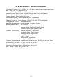
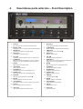
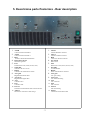
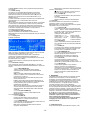
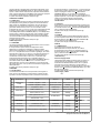
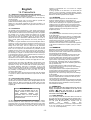
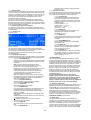
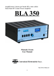
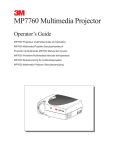
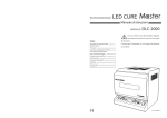
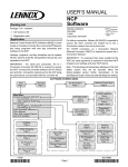
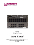
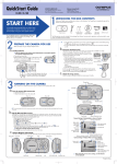
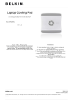
Amplificatore Lineare per bande HF/50MHz a stato solido
Solid-State HF/50MHz Band 1kW Linear Power Amplifier
BLA 1000
Manuale Utente
Users Manual
3 Costruzioni Elettroniche S.n.c.
-1-
1. Introduzione
L'amplificatore lineare BLA 1000 è un amplificatore lineare ad alte prestazioni costruito per
l'uso con tutti i ricetrasmettitori HF in tutti i modi di trasmissione.
Questo amplificatore usa due MosFets MRF157 configurati in classe AB2.
Opera in tutte le bande da 160 (1,8 MHz) a 6 (52 MHz) metri in maniera lineare e senza
interruzioni da 1,5 e 30MHz e da 48 a 55 MHz.
Una ventilazione forzata interna a velocità variabile provvede al raffreddamento di tutte le
parti dell'amplificatore, un circuito elettronico pilotato dal microprocessore ne controlla il
funzionamento.
Due ampi strumenti interni analogici ed un display LCD, vi tengono sempre informati sui
parametri vitali dell'amplificatore, Potenza d'uscita, Potenza riflessa, Corrente di drain,
Tensione di drain, Livello ALC e molti altri parametri sono visualizzabili per avere sotto
controllo ogni momento lo stato di funzionamento dell'amplificatore.
Vi raccomandiamo la lettura del presente manuale in tutte le sue parti prima della messa
in funzione dell'amplificatore.
Conoscere il funzionamento di tutte le sezioni dell'amplificatore vi permetterà un uso più
performante ed eviterà errori che oltre a causare una perdita di potenza d'uscita potrebbe
causare danni ai componenti anche in maniera irreversibile.
Un uso attento e corretto vi farà apprezzare le "performance" del BLA 1000 per molti anni
senza nessun intervento tecnico.
Introduction
The BLA 1000 Linear Amplifier is a high performance amplifier designed for use with all HF
transceivers and all modes of transmission.
The amplifier uses 2 MRF157 MosFets configured for Class AB2 operation.
Operation is possible for all bands from 160 (1.8MHz) to 6 (52MHz) meters and without
interruption from 1.5 to 30 MHz and from 48 to 55 MHz.
It features microprocessor controlled variable speed forced air ventilation that provides
cooling for all areas of the amplifier.
Two large analogue meters and an LCD display show all of the amplifiers operational
parameters; Output power, Reflected power, Drain current, Drain voltage, ALC level, and
other parameters, enabling the operator to see the state of the amplifier at any time. This
allows the user to obtain the maximum performance and avoid any possible operating
errors resulting in a loss of output power and possible irreversible component damage.
Attention to correct operating procedure and operating the amplifier within it’s capabilities
will result in optimim performance and many years of trouble free use.
-2-
2. Indice – Index
1
2
3
4
5
Introduzione – Introduction ..............................................................................................................................
Indice – Index ...................................................................................................................................................
Specifiche, precauzioni - Specifications, Cautions ..........................................................................................
Descrizione parte Anteriore - Front description ...............................................................................................
Descrizione parte Posteriore - Rear description ..............................................................................................
6
Italiano ..............................................................................................................................................................8
6.1 Rimozione dall'imballo ed ispezione ...........................................................................................................8
6.2 Procedura d'installazione ............................................................................................................................8
6.3 Connessione alla rete .................................................................................................................................8
6.4 Antenna .......................................................................................................................................................8
6.5 Massa ..........................................................................................................................................................8
6.6 PERICOLI ...................................................................................................................................................8
7
Funzionamento ................................................................................................................................................8
7.1 Impostazioni iniziali .....................................................................................................................................8
7.2 Orologio .......................................................................................................................................................9
7.3 Standby
.....................................................................................................................................9
7.3.1 Menù
.....................................................................................................................................9
7.3.1.1 ALC Set .......................................................................................................................9
7.3.1.1.1 Max Power ..................................................................................................9
7.3.1.1.2 No Power .....................................................................................................9
7.3.1.2 System ........................................................................................................................9
7.3.1.2.1 Time .............................................................................................................9
7.3.1.2.2 Date .............................................................................................................9
7.3.1.2.3 Day ..............................................................................................................9
7.3.1.2.4 Temp ............................................................................................................9
7.3.1.2.5 Restore default settings ..............................................................................9
7.3.1.3 Antenna .......................................................................................................................9
7.3.1.3.1 Banda ..........................................................................................................9
7.3.1.4 Int. VOX .......................................................................................................................9
7.3.1.4.1 Disabled ......................................................................................................9
7.3.1.4.2 Enabled .......................................................................................................9
7.3.1.4.3 RX Delay .....................................................................................................9
7.3.1.5 P. Supply .....................................................................................................................9
7.3.1.5.1 OFF Delay....................................................................................................9
7.3.1.6 Vent. ............................................................................................................................9
7.3.1.6.1 Vent. Speed .................................................................................................9
7.3.1.7 INFO ............................................................................................................................9
7.4 Operate
.....................................................................................................................................9
7.4.1 Default Setting ...........................................................................................................................10
7.4.2 Visualizzazione stato amplificatore ...........................................................................................10
7.4.2.1 Display LCD ..............................................................................................................10
7.4.2.2 Strumenti Analogici ...................................................................................................10
7.4.2.2.1 MULTIMETER ...........................................................................................10
7.4.2.2.2 OUTPUT POWER .....................................................................................10
7.4.2.3 Indicazioni Lumisose .................................................................................................10
7.4.2.3.1 ON AIR ......................................................................................................10
7.4.2.3.2 WARNING .................................................................................................10
7.4.2.3.3 BAND ........................................................................................................10
7.4.2.3.4 ANTENNA ..................................................................................................10
7.4.3 Comandi ...................................................................................................................................10
7.4.3.1 Keyboard ...................................................................................................................10
7.4.3.2 METER ......................................................................................................................10
7.4.3.3 BAND.........................................................................................................................10
7.4.3.4 AUTO/Manual ............................................................................................................10
7.4.3.5 TX/ON .......................................................................................................................10
7.4.3.6 ANT A/B .....................................................................................................................10
Protezioni
...................................................................................................................................10
8.1 OVER Input Power ...................................................................................................................................10
8.2 OVER Temp
...................................................................................................................................11
8.3 OVER SWR
...................................................................................................................................11
8.4 FILTER FAULT
...................................................................................................................................11
8.5 Vdd Error
...................................................................................................................................11
8.6 OVER Id
...................................................................................................................................11
8.7 LOW Efficiency
...................................................................................................................................11
8.8 Power Supply FAUL...................................................................................................................................11
8
16
2
3
5
6
7
English Precautions ...................................................................................................................................12
16.1 Removal from packaging and inspection ................................................................................................12
16.2 Installation
...................................................................................................................................12
16.3 Connection to AC supply.........................................................................................................................12
16.4 Antenna
...................................................................................................................................12
-3-
17
18
16.5 GROUND
...................................................................................................................................12
16.6 WARNING
...................................................................................................................................12
OPERATION
...................................................................................................................................12
17.1 Initial Settings
...................................................................................................................................12
17.2 Time
...................................................................................................................................13
17.3 Standby
...................................................................................................................................13
17.3.1 MENU ...................................................................................................................................13
17.3.1.1 ALC Setting..............................................................................................................13
17.3.1.1.1 Max Power ..............................................................................................13
17.3.1.1.2 No Power .................................................................................................13
17.3.1.2 System.....................................................................................................................13
17.3.1.2.2 Date .........................................................................................................13
17.3.1.2.3 Day ..........................................................................................................13
17.3.1.2.4 Temp ........................................................................................................13
17.3.1.2.5 Restore default settings ..........................................................................13
17.3.1.3 Antenna .................................................................................................................. 13
17.3.1.3.1 Band ........................................................................................................13
17.3.1.4 Int. VOX .................................................................................................................. 13
17.3.1.4.1 Disabled ..................................................................................................13
17.3.1.4.2 Enabled ...................................................................................................13
17.3.1.4.3 RX Delay .................................................................................................13
17.3.1.5 PSU .........................................................................................................................13
17.3.1.5.1 OFF Delay................................................................................................13
17.3.1.6 Vent. ........................................................................................................................13
17.3.1.6.1 Vent. Speed .............................................................................................13
17.3.1.7 INFO ........................................................................................................................13
17.4 Operate
...................................................................................................................................13
17.4.1 Default Setting .........................................................................................................................14
17.4.2 Monitoring the state of Amplifier..............................................................................................14
17.4.2.1 Display LCD ............................................................................................................14
17.4.2.2 Analogue panel meters .......................................................................................... 14
17.4.2.2.1 MULTIMETER .........................................................................................14
17.4.2.2.2 OUTPUT POWER ...................................................................................14
17.4.2.3 On Air and Warning LED's ......................................................................................14
17.4.2.3.1 ON AIR ....................................................................................................14
17.4.2.3.2 WARNING ...............................................................................................14
17.4.2.3.3 BAND ......................................................................................................14
17.4.2.3.4 ANTENNA ................................................................................................14
17.4.3 Front Panel controls ................................................................................................................14
17.4.3.1 Keyboard .................................................................................................................14
17.4.3.2 METER ....................................................................................................................14
17.4.3.3 BAND.......................................................................................................................14
17.4.3.4 AUTO/Manual ..........................................................................................................14
17.4.3.5 TX/ON .....................................................................................................................14
17.4.3.6 ANT A/B ...................................................................................................................14
Protections
...................................................................................................................................14
18.1 OVER Input Power ..................................................................................................................................14
18.2 OVER Temp
...................................................................................................................................14
18.3 OVER SWR
...................................................................................................................................15
18.4 FILTER FAULT
...................................................................................................................................15
18.5 Vdd Error
...................................................................................................................................15
18.6 OVER Id
...................................................................................................................................15
18.7 LOW Efficiency
...................................................................................................................................15
18.8 Power Supply FAUL.................................................................................................................................15
-4-
3. SPECIFICHE – SPECIFICATIONS
Frequenza - Frequency : 1.5 ~ 30 MHz 48 ~ 55 Mhz all amateur bands including WARC bands
Modi - Mode : AM, FM, SSB, CW, RTTY
Potenza di pilotaggio - RF Drive : 100W typ. (110W max.)
Potenza d'uscita - Output Power : 1.0 kW CW (typ.) (900 W on 1,8 MHz band)
Tensione di drain - Drain Voltage : 48 V
Corrente di drain - Drain Current : 45 A max.
Impedenza d'ingresso - Input Impedance : 50Ω (unbalanced)
Impedenza d'uscita - Output Impedance : 50Ω (unbalanced)
Transistor di potenza - Final Transistor : MRF157 x 2 (MOS FET by M/A COM)
Configurazione - Circuit : Class AB push-pull
Metodo di raffreddamento - Cooling Method : Forced Air Cooling
Microprocessore - MPU : PIC 18F4620
Strumenti - Meters :
Potenza d'uscita - Output Power 2.5 kW
Potenza riflessa - Reflected Power Pr 400W
Corrente di drain - Drain Voltage Vd 60V
Corrente di drain - Drain Current Id 60A
Protezioni – Protections:
Potenze d'ingresso – Input Power
Tensione di drain – Drain Voltage
Corrente di drain – Drain Curren
Errore Filtri – Wrong Filter
R.O.S. - S.W.R.
Temperatura – Temperature
Rendimento - Efficiency
Connettori Ingresso/Uscita - Input/Output Connectors : UHF SO-239 with low loss Teflon
insulator
Alimentazione - AC Power : AC 180 ~ 264 Vac 15,5A max.
Consumo - AC Consumption : 2,2 kVA max. when TX
Dimensioni - Dimension : 495 x 230 x 462 mm (W x H x D)
Peso - Weight : Approx. 30 kg. Or 66,1 lbs.
Accessori - Accessories : AC Power Cord x 1
-5-
4.
Descrizione parte anteriore – Front Description
1. Tastiera
1. Keyboard
2. Display LCD
2. LCD Display
3. Multimetro
3. Multimeter
4. Wattmetro
4. Wattmeter
5. ON AIR
5. ON AIR
6.
WARNING
6.
WARNING
7.
BAND
7.
BAND
8.
ANTENNA
8.
ANTENNA
9.
POWER/ON
9.
POWER/ON
per la navigazione e inserimento dati nei menù
For navigation and data input in the menus
Visualizza l'orario e molti parametri di funzionamento
visualizza il parametro impostato da e
Displays the time and operational parameters
Displays the chosen parametere
Visualizza la potenza d'uscita
Displays output power
Si illumina quando l'amplificatore è in trasmissione
Illuminates during transmission
Indica una condizione di allarme, eccessiva potenza
d'ingresso, eccessiva temperatura, allarme generico
Indica il filtro di banda inserito
Indica l'antenna inserita
Interruttore di accensione dell'amplificatore
Indicates excessive input power, high temperature
and general alarm fault conditions
Indicates the currently selected band filter
Indicates the selected antenna
Amplifier ON/OFF switch
10. Standby/ON
10. Standby/ON
11. METER
11. METER
12. BAND
12. BAND
13. Auto/Manual
13. Auto/Manual
14. TX/ON
14. TX/ON
15. ANT A/B
15. ANT A/B
Interruttore di attivazione dell'amplificatore
Standby / Operate switch
Seleziona quale parametro visualizza ]
Parameter selection]
Selezione manuale del filtro di banda
Manual selection of band filter
Seleziona il modo di selezione dei filtri passa-basso
Mode selection for band filter
attiva manualmente la trasmissione
Manual PTT switch
Seleziona manualmente l'antenna attiva
Antenna selection
-6-
5. Descrizione parte Posteriore - Rear description
1. ANT-B
1. ANT-B
2. ANT-A
2. ANT-A
3. RTX
3. RTX
4. Interruttore di rete
4. Net switch
5. Fuse
5. Fuse
6.
Spina ISO
6.
Fuses box 2x16A (230V) 2x32A (110V)
ISO Plug
7.
RS232
7.
RS232
Connetore SO239 Antenna B
Antenna B SO329 connector
Connetore SO239 Antenna A
Antenna A SO329 connector
Connetore SO239 Ricetrasmettitore
Transceiver SO329 connector
Interruttore generale
Main switch
Portafusibili 2x16A (230V) 2x32A (110V)
Connettore del cavo di rete
Connettore di comunicazione seriale
8. ALC gain
AC Main Socket
Serial communication connector
8. ALC gain
Regolazione azione ALC
9. ALC level
Regolazione soglia ALC
10. ALC
ALC gain setting
9. ALC level
ALC threshold setting
10. ALC
Connettore ALC
ALC connector
11. PTT
11. PTT
12. PTT set
12. PTT set
13. Adesivo
13. Sticker
Connettore PTT
PTT connector
Seleziona il funzionamento della connessione PTT
PTT mode setting
Descrizione connessioni e dati di targa
Connections and technical data
-7-
dell'intensità luminosa di lampadine poste nello stesso
locale dell'amplificatore, i conduttori di rete probabilmente
sono di sezione insufficiente per l'uso in sicurezza dello
stesso.
Italiano
6. Precauzioni
6.1 Rimozione dall'imballo e Ispezione
Rimuovere, con molta attenzione, il BLA 1000 dal proprio imballo,
controllare che il lineare non abbia nessun segno visibile di danni.
Agire delicatamente ogni controllo e interruttore per controllare che
abbiano un normale funzionamento.
Se è rilevato qualche danno, fate una relazione dettagliata ed
inviatela o consegnatela immediatamente al vostro fornitore.
Conservare l'imballo completo da riutilizzarsi in caso di necessità.
E' obbligatorio l'uso dell'imballo originale in caso di rientro presso
un centro di riparazione.
6.2 Procedura d'installazione
L'amplificatore deve essere posto in modo che vi sia un ampio
spazio attorno, in modo che il flusso d'aria sia libero di circolare
permettendo una corretta ventilazione di tutte le parti, non deve
essere esposto direttamente alla luce solare ed il luogoo deve
essere fresco ed asciutto.
Non porre libri, carta, o altri oggetti sulla parte superiore del
BLA 1000, non porre nulla che possa ostruire la griglia posteriore e
laterale. Una limitazione del flusso di ventilazione può danneggiare
in maniera irreversibile il lineare.
Per il dettaglio delle connessioni di un'installazione tipica del
BLA 1000, fare riferimento al capitolo 5. L'ingresso ALC del
ricetrasmettitore va connesso all'uscita ALC (d) del BLA 1000 (fare
riferimento al capitolo 7.3.1.1 per eseguire il corretto setting),
l'uscita PTT del ricetrasmettitore all'ingresso PTT (e) del lineare. In
caso di mancato uso di questa connessione è possibile usare il
comando manuale sul frontale (h)o attivare da menù un circuito
interno al BLA 1000 che fornisce il segnale necessario, per un
miglior controllo della commutazione, si consiglia in ogni caso l'uso
dell'ingresso PTT.
Entrambi i connettori sopra menzionati sono di tipo RCA.
Usare un corto spezzone di cavo coassiale tipo RG-58A/U o RG8A/U o equivalenti per l'interconnessione dell'uscita del
ricetrasmettitore al connettore RTX (]) del BLA 1000.
Per la connessione delle uscite ANT ([ e \) del BLA 1000
all'antenna non usare cavo tipo RG-58 ma solo un cavo che
sopporti ampiamente la potenza d'uscita, cavi adeguati sono
RG8A/U, RG-213/U o equivalenti, si consiglia di usare sempre
entrambe le uscite ANT A e ANT B per evitare che accidentalmente
l'amplificatore venga posto in trasmissione senza un carico, se non
è presente una seconda antenna si può utilizzare un carico fittizio di
potenza adeguata.
Il ricetrasmettitore usato per pilotare il BLA 1000 deve essere in
grado di fornire una potenza pari a 100 W per avere la massima
potenza dichiarata in uscita al lineare.
6.3 Connessione alla Rete
L'alimentatore per il funzionamento del BLA 1000 è incluso al suo
interno, è in grado di operare alle tensioni di rete da 180 a 260 Vac
50/60 Hz. Prima di connettere la spina di rete assicurarsi della
corretta tensione di lavoro scritta sull'adesivo posteriore (g).
ATTENZIONE !!!!
L'uso dell'amplificatore con una
tensione di rete impropria provoca
danni permanenti, la garanzia non
copre
i
danni
provocati
da
un'alimentazione impropria o con un
fusibile non corretto.
6.4 ANTENNA
Il BLA 1000 è costruito per l'uso con antenne che
presentano un carico resistivo di 50Ω sulla frequenza
di lavoro, in caso di uso di un'antenna che non risponde
a questi requisiti si consiglia l'uso di un adattatore
d'impedenza o di un accordatore, in grado di portare
l'impedenza vista dall'amplificatore alla sua uscita
nei limiti richiesti. Si ricorda che accessori a valle
dell'amplificatore devono ampiamente sopportare la
potenza d'uscita dello stesso, accessori inadeguati possono
provocare danni irreversibili all'amplificatore.
6.5 MASSA
Questo amplificatore deve essere connesso all'impianto
di terra della stazione radio.
Verificare che l'impianto di terra della stazione sia di ottima
qualità, questo eliminerà molti disturbi in ricezione, preverrà
accumulo di cariche statiche ed eviterà che ci siano punti a
tensione RF elevata in trasmissione sulle parti metalliche
che è possibile toccare.
Per evitare disturbi RF può essere utile porre una ferrite di
soppressione EMI (Clamp-on ferrite cores) su ogni cavo di
connessione all'amplificatore.
6.6 PERICOLI
All'interno dell'amplificatore sono presenti tensioni elevate e
pericolose. Prima di rimuovere il coperchio dell'amplificatore
assicurarsi di avere disconnesso il cavo di rete ed i cavi di
connessione all'antenna ed al ricetrasmettitore.
Se si sentono rumori od odori anomali, spegnere
immediatamente l'amplificatore, fare un controllo su tutte le
connessioni e rivolgersi ad un centro di assistenza
autorizzato.
Non sottoporre l'amplificatore ad urti, umidità, luoghi
polverosi e caldi, operare una pulizia periodica dagli
accumuli di polvere.
Non immettere in ingresso una potenza maggiore di 110W,
l'eccesso di potenza d'ingresso è potenzialmente distruttiva
e fa' decadere la garanzia.
L'amplificatore è provvisto da molte sofisticate protezioni
ma l'uso reiterato in condizioni di pericolo può comunque
determinare un danno permanente all'amplificatore.
L'uso con un filtro di banda errato o senza un'antenna
collegata può essere distruttivo se è operato alla massima
potenza.
Le regolazioni all'interno dell'amplificatore sono settate in
fase di taratura in fabbrica con una adeguata
strumentazione, la loro modifica fa' decadere la garanzia.
7. FUNZIONAMENTO
Prima di iniziare qualsiasi operazione verificare che la
tensione presente alla presa d’alimentazione di rete
corrisponda alla tensione nominale scritta sull’adesivo
posteriore (g). Verificare che un’antenna adeguata sia
connessa al connettore ANT A del lineare (\).
7.1 Impostazioni iniziali
Il BLA 1000 deve essere connesso ad una presa di rete
indipendente senza interporre adattatori o altri accessori che
potrebbero
provocare
surriscaldamenti
delle
connessioni
danneggiandole.
I conduttori del circuito di rete non devono essere inferiori a
2,5 mm² per tensioni di 200/220/240 Vac o #10 AVG per tensioni di
100/110/120 Vac.
Se durante l'uso del BLA 1000 si nota un notevole abbassamento
-8-
Il ricetrasmettitore, usato per pilotare il BLA 1000, se
necessario, deve essere accordato prima che possa
operare in accoppiamento al lineare. Se è necessario
l’accordo dell’RTX deve essere eseguito con l’interruttore
d posto su Stadby (scritta standby sul display k) oppure
deve essere posizionato su OFF l'interruttore POWER (c).
Prima di usare l'amplificatore è necessario adattare il livello
della tensione ALC al ricetrasmettitore (fare riferimento al
capitolo 7.3.1.1 per eseguire il corretto setting).
Posizionare i comandi del BLA 1000 nel seguente modo
(fare riferimento al paragrafo 4):
Power/ON ....................................OFF
Standby/ON .................................OFF
Meter ...........................................Vdd
Band
AUTO/MANUAL ...........................AUTO
TX/ON...........................................OFF
ANT A/B........................................A
7.2 Orologio
Fornire alimentazione all'amplificatore posizionando su ON
l'interruttore posteriore (^ Par. 5). Si illumina leggermente il Display
LCD e vi viene scritto il modello dell'amplificatore, il giorno della
settimana, la data e l'orario.
La data e l'orario possono essere personalizzati accedendo al
menù di impostazione (x par.x)
7.3 Standby
Portare su On l'interruttore POWER (c par.4), si illumina
completamente il display dell'LCD (\) , si illuminano entrambi gli
strumenti analogici (]e^), si accendono le indicazioni relative alla
banda (a) ed all'antenna (b).
In questa
fase l'amplificatore è in condizioni di attesa, non andrà in
trasmissione se arriverà il comando ma sarà pronto non appena
necessario.
In questa fase il display indicherà:
la prima riga indica il modello, la terza indica rispettivamente lo
stato dell'amplificatore (Standby) l'antenna selezionata (AoB) e
l'impostazione del comando filtri (AUT o MAN), è possibile agire sul
comando ANT A/B per poter selezionare l'antenna connessa al
ricetrasmettitore, anche il selettore filtri(f) se è attivo (commutatore
g su Manual) imposta l'antenna in base alla banda selezionata e le
impostazioni nel menù 7.3.1.2.
7.3.1 MENU'
Quando l'amplificatore è in posizione Standby è accessibile il menù
delle impostazioni. Premere il pulsante OK sulla tastiera ([), si
entra in questo modo in un menù dove è possibile personalizzare
molti dei parametri di funzionamento dell'amplificatore.
Dopo essere entrati nel menù principale, è possibile scorrere tutte
le voci premendo rispettivamente le frecce in alto o in basso, per
entrare nel livello inferiore premere la freccia a destra, per uscire
dal menù premere la freccia a sinistra o scorrere fino alla voce Esc
e premere OK, per salvare le modifiche ad un parametro premere
OK subito dopo averlo modificato. Un asterisco evidenzia
l'impostazione attualmente attiva dove vi sono più voci selezionabili.
7.3.1.1 ALC Setting
La prima voce del menù permette di avere le tensioni necessarie
per la corretta regolazione del livello di ALC.
Prima di iniziare il settaggio porre entrambe le regolazioni nel
pannello posteriore (bec par. 5), con un piccolo cacciavite, tutte in
senso orario. La cura della regolazione del livello ALC migliora le
prestazioni dell'amplificatore e riduce la possibilità di danni in caso
di operazioni errate.
7.3.1.1.1 Max Power
selezionando questa opzione al connettore ALC (d cap.5)
è presente il livello di tensione necessario a settare il
livello di soglia dell' ALC. Con questa voce attiva regolare
-9-
ALC Level (c Cap.5) al punto che la potenza
d'uscita del ricetrasmettitore inizia a scendere.
7.3.1.1.2 No Power
Selezionando questa voce viene settato il
massimo livello di ALC. Con questa voce attiva
regolare ALC Gain (b Cap.5) fino a che la
potenza d'uscita del ricetrasmettitore si riduca
prossima allo 0
7.3.1.2 System
Questa voce permette di accedere alle impostazioni
dell'orologio e dell'unità di misura della temperatura
visualizzata sul display.
7.3.1.2.1 Time
impostare l'ora
7.3.1.2.2 Date
impostare la data, in passi successivi viene
proposto di impostare il giorno, il mese, l'anno ed
il modo di visualizzare la data (giorno-mese-anno,
mese-giorno-anno e anno-mese-giorno)
7.3.1.2.3 Day
impostare il giorno della settimana
7.3.1.2.4 Temp
è possibile selezionare se visualizzare la
temperatura in gradi Celsius o Fahrenheit.
7.3.1.2.5 Restore default settings
E' possibile ripristinare tutte le impostazioni di
fabbrica utilizzando questo menù.
ATTENZIONE !!!! verranno resettate tutte le
impostazioni compresa l'assegnazione
dell'antenna ad ogni singola banda.
7.3.1.3 Antenna
All'interno della voce Antenna è possibile cambiare
l'antenna assegnata di default ad ogni banda.
7.3.1.3.1 Banda
per ogni banda è possibile vedere l'antenna
attualmente assegnata e variarne il valore.
7.3.1.4 Int. VOX
In questo menù è possibile attivare il circuito VOX interno
all'amplificatore. E' comunque sempre preferibile l'uso del
PTT per avere dei tempi di commutazione più ridotti.
7.3.1.4.1 Disabled
Funzione VOX disabilitata
7.3.1.4.2 Enabled
Funzione VOX abilitata
7.3.1.4.3 RX Delay
Quando è abilitata la funzione VOX viene inserito
un ritardo al ritorno in ricezione dell'amplificatore,
di default è settato a 100ms, è possibile settare
questo tempo in 6 passi fissi, 0 – 20 – 50 – 100
– 200 – 500 ms o utilizzando la voce manual
setting tra 0 e 2,5 secondi in passi di 10 ms.
7.3.1.5 P. Supply
qui è impostato il tempo dopo il quale l'alimentatore dello
stadio di potenza si spegne se si è in ricezione.
7.3.1.5.1 OFF delay
Il tempo di spegnimento dell'alimentatore è
selezionabile tra 6 passi fissi, Always ON (sempre
acceso) – 1 – 2 – 5 – 10 – 15 secondi e tra 1 e
137 secondi usando manual setting, di default
l'impostazione è 2 secondi.
7.3.1.6 Vent.
Le ventole che raffreddano l'amplificatore funzionano a
velocità variabile in funzione della temperatura del
dissipatore. Il dato impostato in questa voce determina la
velocità e quindi la rumorosità delle ventole quando la
temperatura dell'amplificatore è tra i 55 e 70 °C.
7.3.1.6.1 Vent. Speed
E' possibile variare la velocità tra 7 passi, circa
dal 20 al 80 % della velocità, di default è 4.
7.3.1.7 Info
Questa voce fornisce informazioni relative alla versione e
data del Firmware.
7.4 OPERATE
Commutando l'interruttore Standby/ON su ON si entra in
modalità Operate ed il BLA 1000 si prepara ad esprimere tutta la
sua potenza.
7.4.1 Default setting
Per avere un uso immediato dell'amplificatore è sufficiente
posizionare il comando di selezione filtri di banda su AUTO,
assicurarsi che l'antenna connessa sulla porta A (\ par.5) sia
adeguata sia in frequenza che in potenza alla banda in cui si
desidera operare.
In questo modo tutte le operazioni del lineare sono completamente
automatizzate e non vi è necessità di alcun intervento
dell'operatore.
Se non sono state cambiate le impostazioni di default, commutando
in trasmissione il ricetrasmettitore, il lineare si pone in attesa del
primo segnale RF in ingresso per determinare la frequenza ed
impostare il corretto filtro di banda. Se alla successiva trasmissione
è necessario cambiare il filtro di banda, il microprocessore
provvederà autonomamente.
7.4.2 Visualizzazione stato Amplificatore
Vengono visualizzati molti dati relativi al funzionamento
dell'amplificatore alcuni dei quali personalizzabili secondo necessità
o preferenze.
7.4.2.1 Display LCD
Il display visualizzerà:
Nella prima riga è visualizzata la scala riferita al Rapporto di Onde
Stazionarie presente all'antenna, da 1:1 a 3:1.
La seconda riga visualizza il livello di ROS in trasmissione.
La terza riga visualizza rispettivamente la frequenza di
trasmissione, l'antenna connessa e l'impostazione del controllo dei
filtri passa-basso (AUT o MAN).
La quarta riga Visualizza la temperatura del dissipatore ed il filtro
inserito.
7.4.2.2 Strumenti analogici
Sono presenti due strumenti analogici (] e ^ par. 4) sui quali
vengono visualizzati alcuni parametri dell'amplificatore e la potenza
d'uscita.
7.4.2.2.1 MULTIMETER (])
Tramite il commutatore METER (e) è possibile
selezionare quale parametro viene visualizzato dal
multimetro :
Vdd è la tensione di alimentazione dello stadio di
potenza, è presente solo in trasmissione e deve essere
compresa tra 45 e 52 Vcc.
Id è la corrente assorbita dallo stadio di potenza, deve
essere inferiore a 45A.
P. Ref. È la quantità di potenza riflessa dall'antenna, è
proporzionale al livello del Rapporto di Onde Stazionarie
ed alla potenza d'uscita, minore è e migliore è
l'adattamento d'impedenza.
ALC è il livello di tensione che è presente sul circuito di
Controllo Automatico della potenza d'uscita. Dipende
dalla temperatura, dal livello di ROS e dallo stato delle
protezioni.
7.4.2.2.2 OUTPUT POWER (^)
Questo strumento indica la potenza RMS d'uscita
dell'amplificatore
7.4.2.3 Indicazioni luminose
7.4.2.3.1 ON AIR (_)
l'accensione della scritta rossa TX indica che
l'amplificatore è in condizioni di trasmissione.
7.4.2.3.2 WARNING (`)
L'accensione di una di queste indicazioni rosse indica uno
stato di pericolo per l'amplificatore.
Pow indica il superamento della massima potenza
d'ingresso all'amplificatore.
-10-
Temp indica il superamento della temperatura di
normale funzionamento.
A indica un errore generico, l'evento che lo ha
generato viene scritto sul display LCD
7.4.2.3.3 BAND (a)
Si illumina la banda relativa al filtro passa-basso
impostato
7.4.2.3.4 ANTENNA (b)
identifica l'antenna connessa all'amplificatore.
7.4.3 Comandi
Sul pannello frontale sono presenti alcuni comandi che
permettono di fare un uso più personalizzato
dell'amplificatore. I comandi manuali son attivi solo quando
l'amplificatore non è in trasmissione.
7.4.3.1 Keyboard ([)
In operate sono attivi solo i due tasti relativi alle
frecce
destra e sinistra, utilizzando questi tasti
è possibile cambiare il parametro visualizzato sul
display LCD nelle prime due righe.
I parametri visualizzabili sono:
Output SWR 1:1 – 3:1
ROS in antenna
Output power 0 – 1,5 KW
Potenza d'uscita
Input Power 0 – 150 W
Potenza in ingresso
PA Power 0 – 3 KW
Potenza assorbita
7.4.3.2 METER (e)
Questo commutatore seleziona quale parametro
verrà visualizzato nello strumento MULTIMETER
( 7.4.2.2.1)
7.4.3.3 BAND (f)
Con questo commutatore è possibile selezionare
il filtro passa-basso corretto per la banda in uso.
Funziona solo in modalità Manual di (g).
7.4.3.4 AUTO/MANUAL (g)
con questo commutatore è possibile impostare la
selezione dei filtri di banda, se in AUTO
l'impostazione è automatica se in Manual è
impostata tramite il commutatore BAND (e).
7.4.3.5 TX/ON (h)
Con questo pulsante è possibile portare in
trasmissione l'amplificatore, è utile se si sta
utilizzando un ricetrasmettitore senza l'uscita PTT.
7.4.3.6 ANT A/B (i)
Tramite questo pulsante si può cambiare
l'antenna connessa con l'amplificatore in
trasmissione e con il ricetrasmettitore in ricezione.
La variazione permane fino alla variazione della
banda in uso, quando cambia la banda in uso
l'antenna assegnata è quella assegnata alla
banda (7.3.1.2)
8. Protezioni
L'amplificatore BLA1000 possiede vari sofisticati circuiti di
protezione che intervengono in caso di necessità per
proteggere i componenti dell'amplificatore. Tutte le misure
sono gestite da un potente microprocessore che provvede
ad identificare ogni possibile situazione di pericolo ed
avvisa l'operatore con un segnale acustico e luminoso
scrivendo sul display LCD il motivo dell'allarme.
Se la situazione di pericolo lo richiede, l'amplificatore viene
bloccato spegnendo l'alimentatore dello stadio di potenza e
portando il sistema in standby, in questo caso è necessario
eliminare la causa dell'intervento della protezione e
spegnere e riaccendere l'amplificatore tramite l'interruttore
di rete (^ par.5) o l'interruttore POWER/ON (c par.4).
Nonostante le sofisticate protezioni l'uso reiterato in
condizioni di pericolo può comunque determinare un
danno permanente all'amplificatore.
L'uso con un filtro di banda errato o senza un'antenna
collegata può essere distruttivo se è operato alla
massima potenza.
8.1 OVER Input Power
Se la potenza di ingresso all'amplificatore supera i 110W
vengono attivati un segnale audio e lampeggia l'indicazione rossa
Pow dell'indicatore WARNING (` par.4). Se la potenza d'ingresso
supera i 115W il lineare viene bloccato, l'operatore sentirà l'allarme
audio, verrà accesa fissa la scritta Pow e sarà necessario spegnere
e riaccendere l'amplificatore per resettare la protezione.
In questi casi il Display indicherà nella prima riga:
OVER INPUT POWER
processore segnala un “FILTER FAULT”, se il funzionmento
rimane dentro i limiti di sicurezza viene emesso un segnale
audio e lampeggia il simbolo rosso A dell'indicatore
WARNING (` par.4), se c'è rischio per l'integrità del
sistema l'amplificatore viene bloccato, viene acceso fisso il
segnale di pericolo e si può udire il segnale di allarme. Per il
ripristino è necessario spegnere l'amplificatore.
In questi casi il Display indicherà nella prima riga:
FILTER FAULT
8.2 OVER Temp.
La temperatura del punto di contatto tra i dispositivi RF di potenza
ed il dissipatore viene gestita per regolare la velocità di rotazione
delle ventole che raffreddano il dissipatore. Se la temperatura è
inferiore a 35°C le ventole sono ferme, tra 40 e 50 °C le ventole
girano alla velocità minima, tra 55 e 70°C la velocità e media
(impostata nel menù 7.3.1.6), tra 75 e 80 °C la velocità delle ventole
è massima, viene emesso un segnale acustico e lampeggia la
scritta Temp dell'indicatore WARNING (` par.4). Se la temperatura
supera gli 80°C il sistema viene bloccato, sarà presente il segnale
acustico di allarme, la scritta Pow diventa fissa. Il ripristino delle
normali funzionalità avverrà quando la temperatura del dissipatore
diventerà inferiore a 60°C.
In questi casi il Display indicherà nella prima riga:
OVER Temperature
8.5 Vdd Error
Se la tensione di alimentazione dello stadio di potenza non
rientra tra 45 e 52 Vcc viene emesso un segnale di allarme
si accende il simbolo rosso A dell'indicatore WARNING (`
par.4) e viene bloccato l'amplificatore.
In questi casi il Display indicherà nella prima riga:
Vdd Error
8.6 OVER Id
La corrente massima richiesta dall'amplificatore è di 45A,
se viene superata viene emesso un segnale di allarme si
accende il simbolo rosso A dell'indicatore WARNING (`
par.4) e viene bloccato l'amplificatore.
In questi casi il Display indicherà nella prima riga:
OVER Id
8.3 OVER SWR
Un sensore posto dopo il gruppo filtri passa-basso misura i livelli di
potenza diretta e riflessa all'antenna.
Il microprocessore opera il calcolo del Rapporto di Onde
Stazionarie e lo utilizza per proteggere lo stadio di potenza
dall'eccessiva dissipazione. La condizione ottimale è con un ROS
fino a 1.5:1, l'amplificatore lavora al massimo guadagno. Se il ROS
aumenta oltre il valore di 1,5:1 fino a 2:1 il processore introduce un
valore di ALC necessario per mantenere lo stadio di potenza in
condizioni di sicurezza. Oltre il valore di 2:1, l'operatore viene
avvisato del livello di ROS alto con un segnale acustico e il
lampeggio del simbolo rosso A dell'indicatore WARNING (` par.4).
Se il valore di ROS supera il valore di 2.5:1 avviene il blocco
dell'amplificatore, l'avviso sonoro dell'allarme e l'accensione fissa
del simbolo di pericolo. Per il ripristino è necessario lo spegnimento
dell'amplificatore.
In questi casi il Display indicherà nella prima riga:
OVER SWR
8.7 LOW Efficiency
Il microprocessore controlla che l'efficienza
dell'amplificatore sia sempre ottimale, se si riduce
eccessivamente viene emesso un segnale di allarme si
accende il simbolo rosso A dell'indicatore WARNING (`
par.4) e viene bloccato l'amplificatore.
In questi casi il Display indicherà nella prima riga:
LOW Efficiency
8.8 Power Supply FAULT
L'alimentatore dello stadio di potenza ha al suo interno un
microprocessore che gestisce in completa autonomia il
funzionamento dell'alimentatore stesso. Se vi è qualche
anomalia comunica la condizione al microprocessore
principale, viene emesso un segnale di allarme si accende il
simbolo rosso A dell'indicatore WARNING (` par.4) e viene
bloccato l'amplificatore.
In questi casi il Display indicherà nella prima riga:
Power Supply FAULT
8.4 FILTER FAULT
La scheda filtri di banda invia al microprocessore vari segnali di
stato, servono per identificare il funzionamento regolare del filtro
impostato. Se il filtro impostato è errato o presenta un'anomalia il
8.8
LED Note
Nr
Protezione
Causa
Display
Reset
1
Potenza in ingresso > 110W
Input Power >100W
Nessuna azione
POW*
2
OVER Input
Power
Potenza in ingresso > 115W
OVER input Power
Standby ¹
POW
3
OVER Temp
Temperatura >80°C
OVER Temp!
Automatico <60°C
Temp
ROS in antenna > 2:1
SWR > 2
Nessuna azione
A*
ROS in antenna >2.5:1
OVER SWR
Standby ¹
A
FILTER FAULT
Standby ¹
4
5
6
7
OVER SWR
FILTER FAULT
ROS ingresso filtri > 2,5:1
Potenza resa < 70%
A*
A
8
Vdd ERROR
Tensione <45V o >52V
Vdd ERROR
Standby ¹
A
9
OVER Id
Corrente Id > 45A
Id ERROR
Standby ¹
A
10
LOW Efficiency
Potenza in antenna < 40%
LOW Efficiency
Standby ¹
A
11
Power Supply
Fault
Malfunzionamento alimentatore
Power Supply Fault
Power OFF ²
A
¹ commutare l'interruttore Standby OFF e poi ON (d par.4)
² spegnere l'interruttore di rete (^ par.5)
-11-
English
16. Precautions
16.1 Removal from packaging and inspection
Carefully remove the amplifier from it’s packaging, and inspect for
any sign of damage incurred during shipping.
With care operate each button / switch to check mechanically they
operate correctly.
If any damage is found, note in as much detail as possible the
problem and immediately contact your supplier.
Retain all of the original packaging as this must be used if it is
necessary to return the amplifier to an approved service centre for
any reason.
16.2 Installation
The amplifier must be positioned in a cool and dry area that has
sufficient space surrounding the amplifier to allow good ventilation
to all surfaces and free flow of the surrounding air. Do not operatre
the amplifier if it is in direct contact with sunlight. Do not place
books, paper or other objects on the top surface of the amplifier,
and ensure that that the ventilation grilles on the rear and side
panels are free from obstructions. Reduced airflow due to one or
both of these grilles being obstructed can severly damage the
amplifier.
For details of a typical installation of the BLA1000 amplifier refer to
Chapter 5. The ALC input from the transceiver connects to the ALC
output (d) of the BLA 1000 (refer to Chapter 7.3.1.1 for the correct
setting of the ALC level), The PTT output from the transceiver
should be connected to the PTT input of the BLA1000 (e). In case
there is no PTT output from the transceiver it is possible to use the
amplifier with the manual PTT switch from the front panel (h), or
activate from a menu a circuit inside the BLA1000 that will supply
the necessary PTT signal. For the best control of TX/RX switching it
is recommend that the PTT input is utilised. Both the ALC and PTT
input connectors are RCA phono type.
Use a short length coaxial cable, type RG-58A/U,RG-8A/U or
equivalent for the connection between the output of the transceiver
and the input of the amplifier, connector RTX (]) del BLA 1000.
Connection from the output, ANT ([ e \) of the BLA1000 to the
antenna should not be made with low power RG-58 type cable or
equivalent, but only with a coaxial cable of sufficient power rating,
for example RG-8A/U, RG-213/U or equivalent. If one of the
antenna connectors ANT A or ANT B is not used it is suggested that
a dummy load of sufficient power rating is connected, thus avoiding
the possibility of transmitting into one of the ANT A or ANT B
connectors without load.
The transceiver used for the input of the BLA1000 must be capable
of a power of 100W to obtain the maximum output from this linear
amplifier.
16.3 Connection to AC supply
The BLA 1000 amplifier features an internal power supply and can
operate from the mains AC network with a voltage between 180 and
260Vac 50/60 Hz. Before connecting the amplifier verify that this
voltage is in accordance with that specified on the rear panel of the
amplifier (g).
voltages di 200/220/240 Vac or #10 AVG for voltages
100/110/120 Vac.
If during operation of the BLA1000 it is noticed that the
intensity of the surrounding household lighting reduces,
then it is likely that the AC network cables are of insufficient
diameter for the safe operation of the amplifier.
16.4 ANTENNA
The BLA 1000 is designed for use with antennas that
present a resistive load of 50Ω at the frequency of
operation. In the case that the antenna does not correspond
to this it will be necessary to use a system of impedance
matching such as an antenna tuner to provide the correct
impedance transformation. If using such a device it must be
capable of withstanding the output level of the amplifier
otherwise damage to the matching device and or the
amplifier may result.
16.5 GROUND
This amplifier must be connected to the RF ground system
of the radio station.
Verify that the RF ground of the station is of suitable quality,
this will eliminate noise problems on reception, prevent the
build up of static charge and avoid points of high RF
voltages during transmission on metallic objects that may
come into contact with the operator. To avoid RF
interference it can be useful to use a Ferrite EMI suppressor
on all cables connected to the amplifier. (Clamp on Ferrite
cores).
16.6 WARNING!
Dangerous high voltages are present inside the amplifier.
Before removing the cover from the amplifier, it is essential
that the AC power cable, coaxial cables to the antennas and
the transceiver are disconnected.
If during operation it is noticed an abnormal noise or odor,
switch off the amplifier immediately and check all of the
connecting cables and if necessary return to a authorised
service centre for testing. Do not subject the amplifier to
physical shock, high humidity, dusty environments or
excessive heat. Periodically clean any accumulated dust
from the amplifier especially around ventilation grilles with a
soft dry antistatic cloth.
Do not exceed more than 110W on the input to the
amplifier. Excessive drive on the input may cause damage
and invalidate the warranty.
This amplifier features several sophisticated protection
circuits however using the amplifier in a manner other than
that described in the operating instructions may be
dangerous to the user and may cause permenant damage
to the amplifier.
Use of the amplifier with an incorrect band filter selected or
without a suitable antenna connected at maximum power
may be distructive to the amplifier.
The internal set-up parameters of the amplifier are adjusted
on an individual basis for each amplifier during a set-up and
test phase at the factory. Modification of these parameters
will invalidate the warranty.
17. OPERATION
Before use verify that the voltage present
supply corresponds to that written on the
amplifier. (g). Verify also that there is
antenna, correctly adjusted connected to
Connector of the amplifier (\).
ATTENZIONE !!!!
The use of this amplifier with an AC
voltage outside of that stated may
cause permanent damage. The
gaurantee does not cover damage
sustained from this or from the use of
an incorrect fuse.
on the AC
rear of the
a suitable
the ANT A
17.1 Initial Settings
The BLA 1000 must be connected directly to the mains AC network
with the supplied AC cable, without the use of adaptors or other
accesories which may cause excessive heating due to the power
requirements of this amplifier. The cables of the AC network the
amplifier is connected to must not be smaller than 2,5 mm² for
-12-
If it is necessary to tune the transceiver before use with the
BLA 1000 this may be carried out with the amplifier used in
Standby mode. Switch d to Stadby (standby displayed on
the LCD panel k) alternatively the amplifier must be
switched
OFF,
POWER
switch
(c).
Before using the amplifier it is necessary to adjust the level
of the ALC voltage for the transceiver. (refer to Chapter
17.3.1.1 for correct adjustment).
Set the front panel controls in the following positions, (with
reference to to paragraph 4):
Power/ON
Standby/ON
Meter
Band
AUTO/MANUAL
OFF
OFF
Vdd
AUTO
17.2 Time
Switch the rear panel AC power switch to ON (^ Par. 5). The LCD
display will illuminate and the model of the amplifier, day of the
week, date and time will be displayed.
The date and time can be altered by accessing the settings menu(x
par.x)
17.3 Standby
Switch the POWER switch to ON (c par.4), The LCD display will
illuminate(\) , both analogue panel meters will illuminate (]e^),
also the LED of the corresponding selected band filter (a) and
antenna output (b). In this phase the amplifier is in Standby and
will not go into trasmit if the PTT is operated.
The LCD display shows:
The first row indicates the model number, the third row shows the
state of the amplifier (Standby), antenna selection (A/B) and the
status of the filter selection, either automatic or manual (AUT or
MAN). It is possible to to change the antenna (A/B) selection and
also the filter selection (Switch f), if it is active, (Switch g to
manual). The antenna A/B selection may also be automatically
assigned to a particular filter, menu 7.3.1.
17.3.1 MENU
When the amplifier is in Standby mode, it is possible to access the
the settings menu. Press the button OK on the keypad ([). In this
mode it is possible to change many of amplifiers parameters to suit
the operators requirements.
After entering the settings menu, it is possible to access all of the
sub menus by pressing either the up or down arrow keys on the
keypad. To enter a sub menu press the right arrow key. To exit a
sub menu press the left arrow key, or cycle through the settings
menu until Esc and press OK. To save any modifications to a
particular parameter press OK immediately after a modification is
made. An asterisk is displayed to indicate the active parameter
where it is possible to make a modification.
17.3.1.1 ALC Setting
This menu allows adjustment of the ALC voltage for the correct
regulation of the ALC level.
To begin set both the trimmers on the rear panel (bec par. 5),
using a small screwdriver, fully clockwise. Correct adjustment of the
ALC level maximises the performance of the amplifier and reduces
the possibility of damage incase of operator error.
Selecting this option it is possible to adjust the
voltage level of the ALC (d cap.5) connector to adjust the
ALC threshold. Adjust the level to the point that the output
power of the transceiver just starts to decrease.
17.3.1.1.2 No Power
selecting this option it is possible to adjust the
maximum level of the ALC. Adjust the ALC Gain b Chap.5
until the output power of the transceiver approaches zero.
17.3.1.2 System
This menu allows access to the settings of the clock, date
and the units of measurement of temperature as seen on
the display.
17.3.1.2.1 Time
Setting the time
17.3.1.2.2 Date
Setting the date, (day, month, year), and the
mode in which it is displayed eg.(day-month-year, monthday-year e year-month-day)
17.3.1.2.3 Day
Setting the day of the week
17.3.1.2.4 Temp
It is possible to change the temperature display
between degrees Celsius or Fahrenheit.
17.3.1.2.5 Restore default settings
It is possible to return all user modified data back
to default factory settings.
ATTENTION !!!!
This will reset all user modified data, including
band assigned antenna settings for all bands.
17.3.1.3 Antenna
This menu allows the choice of the default Antenna, (A or
B) for each individual band.
17.3.1.3.1 Band
For each band it is possible to see and change
the default antenna selection (A or B).
17.3.1.4 Int. VOX
In this menu it is possible to activate the amplifiers internal
VOX circuit. It is preferable that the PTT switching time be
kept as short as possible.
17.3.1.4.1 Disabled
VOX Disabled
17.3.1.4.2 Enabled
VOX Enabled
17.3.1.4.3 RX Delay
When VOX is active, this controls the delay from
TX back to RX, The default setting is 100ms, It is possible
to choose between the following preset delay times, 0 – 20
– 50 – 100– 200 – 500 ms or using the manual setting
between 0 and 2,5 seconds in steps of 10 ms.
17.3.1.5 PSU
Here it is possible to set the time that the drain supply to the
transistors is switched off, when returning from TX to RX.
17.3.1.5.1 OFF delay
The switch off time of the power supply is
selectable in 6 fixed steps, Always ON – 1 – 2 – 5 – 10 –
15 secondi and between 1 and 137 seconds using the
manual setting, The default setting is 2 seconds.
17.3.1.6 Fan.
The cooling fans operate at variable speed in conjunction
with the temperature of the heatsink. It is possible to select
the speed and therefore the noise generated by the fans
when the temperature is between 55 e 70 °C.
17.3.1.6.1 Fan Speed
It is possible to adjust the speed in 9 steps, that
correspond to 30 to 70 % of the fans total speed. The
default setting is 5 corresponding to 50%. (1-30% 2-35% 340% 4-45% 5-50% 6-55% 7-60% 8-65% 9-70%)
17.3.1.7 Info
This displays the version and date of the current Firmware.
17.4 OPERATE
Moving the switch Standby/ON to ON enters the mode
Operate and the amplifier is active.
17.3.1.1.1 Max Power
-13-
17.4.1 Default setting
To use the amplifier immediately it is sufficient to position the switch
for the selection of the band pass filters to AUTO. Ensuring that the
antenna is connected to the ANT A (\ par.5) connector and that it is
suitable for the desired frequency of operation. In this mode all of
the functions of the amplifier are completely automatic and no
operator intervention is required.
If all menus remain at their default settings when operating the
transceiver in TX the amplifier will automatically measure the input
frequency and select the correct band filter. If the operator changes
the transmit frequency the microprocessor will automatically change
to the correct band filter if necessary.
17.4.2 Monitoring the state of the Amplifier
It is possible to monitor many of the amplifiers parameters during
operation and the operator may choose which parameters they wish
to see displayed.
17.4.2.1 Display LCD
Il display shows:
On the first row a scale of Antenna VSWR is shown in the range
from 1.1:1 to 3.0:1.
The second row displays the current value during transmission.
The third shows transmit frequency, antenna selection (A/B) and the
control setting of the band filters (Auto / Manual).
The fourth row shows heat-sink temperature and the currently
selected band filter.
17.4.2.2 Analogue panel meters
There are two analogue panel meters (] e ^ par. 4) They are used
to display some of the amplifiers parameters and the output power.
17.4.2.2.1 MULTIMETER (])
Using the rotary switch METER (e) it is possible to select
between the following parameters to be displayed on the
multimeter:
Vdd The drain voltage of the transistors during
transmission, which must be between 45 e 52 Vcc.
Id The drain current of the transistors during
transmission , which must be below the maximum of 45A.
P. Ref. Reflected power from the antenna which is
proportional to the level of the antenna VSWR at the
current output power. Low values indicate a good
impedance match to the antenna.
ALC The voltage level that is present in the circuit that
automatically controls the output power. This depends on
the heatsink temperature, the level of VSWR and the
state of the protection circuits.
17.4.2.2.2 OUTPUT POWER (^)
Displays the RMS output power of the amplifier.
17.4.2.3 On Air and Warning LED’s
17.4.2.3.1 ON AIR (_)
Illuminates red during transmission.
17.4.2.3.2 WARNING (`)
If any of the three warning LED’s illuminate red then it is
indicating there is a problem with the amplifier and
transmission should be immediately stopped until the
problem is rectified.
Pow indicates that the input power to the amplifier been
exceeded.
Temp Indicates that the temperature has risen above an
acceptable operating level.
A indicates a general error, the cause of which is
displayed on the LCD display.
17.4.2.3.3 BAND (a)
Illuminates green to show the currently selected band
filter
17.4.2.3.4 ANTENNA (b)
-14-
Illuminates red to show the currently selected
antenna (A or B)
17.4.3 Front panel controls
On the front panel there are several controls that allow the
user to operate and adjust the amplifier. These controls are
only active when the amplifier is not in transmission.
17.4.3.1 Keyboard ([)
In operate mode only two keypad buttons are
active (Left and Right arrow), using these two
buttons it is possible to change the parameters
displayed on the LCD panel on the top two rows.
Available choices:
Antenna VSWR 1:1 – 3:1
Output power 0 – 1,5 KW
Input Power 0 – 150 W
PA Power 0 – 3 KW
17.4.3.2 METER (e)
This rotary switch selects the parameter to be
displayed in the analogue panel meter
(Multimeter 7.4.2.2.1)
17.4.3.3 BAND (f)
Rotary switch used to select the correct band filter
for the transmission frequency, when in manual
mode.(g).
17.4.3.4 AUTO/MANUAL (g)
Choose between automatic and manual band
filter selection. (e).
17.4.3.5 TX/ON (h)
Use this switch to manually put the amplifier into
transmit, This can be useful if the transceiver
does not have a PTT output.
17.4.3.6 ANT A/B (i)
Used to change the active antenna connected to
the Amplifier / Transceiver. Antenna A or B can
be selected manually or assigned to a specific
band or bands. (17.3.1.2)
18. Protections
The BLA 1000 features several sophisticated protection
circuits that will interrupt operation if necessary in order to
protect the amplifier from damage. These are controlled by
a powerful microprocessor that can identify all possible fault
conditions and alert the operator with either an audible
error tone or by means of a error message on the the LCD
display. If necessary the protection circuits will shut down
the power supply to the amplifier section and return the
amplifier to Standby. In this case it will be necessary to
eliminate the cause of the problem and reset the amplifier
by switching the AC supply off and on. (^ par.5) or switch
POWER/ON (c par.4).
Despite sophisticated protection, operating the
amplifier repeatedly after an error has been reported
without any correction may cause permanent damage.
The use of an incorrect band filter or transmitting
without a suitable antenna connected to the amplifier at
maximum power may cause irreversible damage.
18.1 Excessive Input Power
If the input power from the transceiver rises above 110W an
audible signal is heard and the Pow WARNING LED will
illuminate (` par.4). If the input power then rises above
115W the amplifier will be shut down, an audible error tone
will be emitted and the Pow warning LED will remain
illuminated. It will then be necessary to restart the amplifier
by switching the amplifier off and then back on to reset the
protection. In the above case the LCD display will show:
OVER INPUT POWER, on the first row.
18.2 OVER Temp.
The temperature at the point of contact between the
transistors and the heatsink regulates the rotation speed of
the heatsink cooling fans. If the temperature is below 35°C
the fans are off, between 40 and 50 °C the fans turn at
minimum speed, between 55 and 70°C medium speed (also
set from menu 17.3.1.6), between 75 e 80 °C the speed is
maximum, an audible tone is also sounded and the Temp
warning LED illuminates (` par.4). If the temperature increases
above 80°C the amplifier will shut down, the audible warning will
continue and the Temp warning LED will remain illuminated. The
amplifier will return to normal operation when the temperature drops
below 60°C.
In the above case the LCD Display will show: OVER Temperature
on the first row.
on the first row.
18.5 Vdd Error
If the transistor drain voltage deviates outside of acceptable
limits, between 45 and 52 Vcc, an audible error tone will be
emitted, the general A WARNING (` par.4) LED will
illuminate and the amplifier will be shut down. In this case
the LCD display will show: Vdd Error on the first row.
18.3 Excessive VSWR
A sensor positioned after the low Pass Filters section measures the
level of forward and reflected power on the antenna. The
microprocessor calculates the VSWR and is used to protect the
amplifier from excessive dissipation in the case of high VSWR. The
amplifier operates at it’s best when the VSWR is below 1.5:1. If the
VSWR increases above 2.0:1 the microprocessor introduces a level
of ALC necessary to maintain the output power at a safe level.
Above 2.0:1 an audible error tone will be emitted and the general
warning LED will illuminate A (` par.4). If the level of VSWR
increases above 2.5:1 the amplifier will be shut down. The audible
warning will continue and the warning LED will remain on. To reset
the amplifier it will be necessary to switch the amplifier off and back
on. In this case the LCD display will show: OVER SWR on the first
row.
18.6 OVER Id
The maximum current required by the amplifier is 45A, if
this value is exceeded then an audible error tone is emitted,
the general A WARNING (` par.4) LED will illuminate and
the amplifier will be shut down. In this case the LCD display
will show: OVER Id on the first row.
18.7 LOW Efficiency
The microprocessor ensures that the efficiency of the
amplifier is always optimal. If the efficiency reduces
excessively then an audible error tone will be emitted, the
general A WARNING (` par.4) LED will illuminate and the
amplifier will be shut down. In this case the LCD display will
show: LOW Efficiency on the first row.
18.8 Power Supply FAULT
The power supply for the transistors has its own internal
microprocessor that controls all aspects of its operation. If a
fault condition arises this will be communicated to the main
microprocessor and an audible error tone will be emitted,
the general A WARNING (` par.4) LED will illuminate and
the amplifier will be shut down. In this case the LCD display
will show: Power Supply Fault on the first row.
18.4 FILTER FAULT
The band pass filter PCB is controlled and monitored by the
microprocessor in order to verify the correct filter is selected. If the
current filter is incorrect or has a problem during use the processor
will signal a “FILTER FAULT”, If the fault allows the amplifier to
continue operation without damage then an audible error tone will
be emitted and the general A WARNING (` par.4) will illuminate. If
there is a risk of damage then the amplifier will be shut down. The
audible warning will continue and the warning LED will remain on.
To reset the amplifier it will be necessary to switch the amplifier off
and back on. In this case the LCD display will show: FILTER FAULT
LED Note
Nr
Protezione
Causa
Display
Reset
1
Input power > 110W
Input Power >100W
No action
POW*
2
OVER Input
Power
Input power > 115W
OVER input Power
Standby ¹
POW
3
OVER Temp
Temperature >80°C
OVER Temp!
Automatic <60°C
Temp
Antenna VSWR > 2:1
SWR > 2
No action
A*
Antenna VSWR >2.5:1
OVER SWR
Standby ¹
A
FILTER FAULT
Standby ¹
4
5
6
7
OVER SWR
FILTER FAULT
Filter input VSWR > 2,5:1
Power efficiency < 70%
A*
A
8
Vdd ERROR
Voltage <45V o >52V
Vdd ERROR
Standby ¹
A
9
OVER Id
Current Id > 45A
Id ERROR
Standby ¹
A
10
LOW Efficiency
Power to antenna < 40%
LOW Efficiency
Standby ¹
A
11
Power Supply
Fault
Power supply malfunction
Power Supply Fault
Power OFF ²
A
¹ switch Standby switch OFF and then ON (d par.4)
² switch off main AC switch (^ par.5)
-15-