1
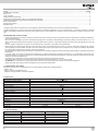
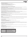
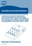
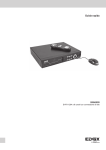
Manuale per il collegamento e l’uso Connection and operating manual EAM8 - EAM9 Attuatore per cancelli battenti 230 Vac Actuator for swing gates 230 Vac C Legenda A - Attuatore lineare B - Centralina di comando C - Lampeggiante D - Radiocomando 2 canali E - Coppia di fotocellule F - Selettore G - Elettroserratura 2x0,5 mm2 + RG59 F 3x0,5 mm2 E 2x0,5 mm2 E B 4x0,5 mm2 2x0,5 mm2 A A G 4x0,75 mm2 4x0,75 mm2 230/120 Vac 3x0,5 mm2 Key A - Linear operator B - Control unit C - Flashing light D - 2-channel remote control E - Pair of photocells F - Selector G - Electrical lock D Fig. 1 909 mm (EAM8) 1109 mm (EAM9) 198 mm 300 mm (EAM8) 400 mm (EAM9) 100 mm 875 mm (EAM8) 1075 mm (EAM9) 45 mm 60 mm 125 mm 62.5 mm 102 mm Fig. 2 155 mm Fig. 3 2 I GB A B EKKO 300A (EAM8) EKKO 400A (EAM9) α A (mm) B (mm) α A (mm) B (mm) 110° 100 100 110° 120 120 110° 120 120 110° 150 150 105° 130 130 110° 170 170 100° 140 140 105° 180 180 90° 150 150 100° 190 190 90° 200 200 C Fig. 4 R R Fig. 5 Fig. 6 Fig. 7 Fig. 8 C I GB 3 Indice:...................................................................................................................................................................................................................... Pagina Caratteristiche di prodotto.................................................................................................................................................................................................. 4 Dati tecnici.......................................................................................................................................................................................................................... 4 Limiti di impiego.................................................................................................................................................................................................................. 4 Predisposizione impianto tipo............................................................................................................................................................................................. 5 Determinazione della posizione del fulcro di rotazione dell’attuatore................................................................................................................................. 5 Installazione delle staffe e posizionamento dell’attuatore sulle staffe................................................................................................................................ 5 Sblocco dell’attuatore......................................................................................................................................................................................................... 5 Collegamento elettrico........................................................................................................................................................................................................ 5 Manuale utente................................................................................................................................................................................................................... 6 Le seguenti informazioni di sicurezza sono parti integranti ed essenziali del prodotto e devono essere consegnate all’utilizzatore. Leggerle attentamente in quanto forniscono importanti indicazioni riguardanti l’installazione, l’uso e la manutenzione. E’ necessario conservare il presente modulo e trasmetterlo ad eventuali subentranti nell’uso dell’impianto. L’errata installazione o l’utilizzo improprio del prodotto può essere fonte di grave pericolo. AVVERTENZE PER L’INSTALLATORE - Leggere attentamente le avvertenze contenute nel presente documento in quanto forniscono importanti indicazioni riguardanti la sicurezza di installazione, d’uso e di manutenzione. - Dopo aver tolto l’imballaggio assicurarsi dell’integrità dell’apparecchio. Gli elementi dell’imballaggio (sacchetti di plastica, polistirolo espanso, ecc.) non devono essere lasciati alla portata dei bambini in quanto potenziali fonti di pericolo. L’esecuzione dell’impianto deve essere rispondente alle norme CEI vigenti. - Prima di collegare l’apparecchio accertarsi che i dati di targa siano rispondenti a quelli della rete di distribuzione. - Questo apparecchio dovrà essere destinato solo all’uso per il quale è stato espressamente concepito, e cioè per i sistemi di automazione per cancelli, porte da garage e barriere stradali. Ogni altro uso è da considerarsi improprio e quindi pericoloso. Il costruttore non può essere considerato responsabile per eventuali danni derivanti da usi impropri, erronei ed irragionevoli. - Prima di effettuare qualsiasi operazione di pulizia o di manutenzione, disinserire l’apparecchio dalla rete di alimentazione elettrica, spegnendo l’interruttore dell’impianto. - In caso di guasto e/o di cattivo funzionamento dell’apparecchio, togliere l’alimentazione mediante l’interruttore e non manomettere l’apparecchio. Per l’eventuale riparazione rivolgersi solamente ad un centro di assistenza tecnica autorizzato dal costruttore. Il mancato rispetto di quanto sopra può compro mettere la sicurezza dell’apparecchio. - L’installatore deve assicurarsi che le informazioni per l’utente siano presenti sugli apparecchi derivati. - Tutti gli apparecchi costituenti l’impianto devono essere destinati esclusivamente all’uso per cui sono stati concepiti. - ATTENZIONE: per evitare di ferirsi, questo apparecchio deve essere assicurato alla parete secondo le istruzioni di installazione. - Questo documento dovrà sempre rimanere allegato alla documentazione dell’impianto. 1. Caratteristiche di prodotto: Attuatore lineare 230 Vac a montaggio esterno per cancelli battenti residenziali e industriali dotato di: - spinta in asse - sblocco a chiave personalizzata e leva - staffe di ancoraggio saldabili, avvitabili e regolabili 2. Dati tecnici Descrizione Alimentazione motore elettrico Assorbimento massimo motore elettrico Potenza massima motore elettrico Spinta massima Lunghezza massima anta Peso massimo anta (alla lunghezza max) Apertura massima Tempo di apertura Grado di protezione Temperatura di funzionamento Condensatore Dimensioni Peso Frequenza di utilizzo Corsa utile EAM8.L/EAM8.R EAM9.L/EAM9.R 230 Vac 50/60 Hz 1,1 A 240 W 2800 N 3m 4m 200 Kg 110° min. 13sec. max 20 sec. min. 16sec. max 27 sec. IP54 Da -20 a +50C° 8 μF Vedere fig. 2 5,7 Kg 6 Kg 50% 300 mm 400 mm 3. Limiti di impiego: Lunghezza anta (metri) 1,5 2 2,5 3 3,5 4 4 Peso anta (kg) EKKO 300A (EAM8) 580 380 250 200 - Peso anta (kg) EKKO 400A (EAM9) 450 320 240 200 I 4. Predisposizione impianto tipo: Prima di procedere all’installazione dell’automatismo, controllare che: - le cerniere del cancello siano robuste e efficienti e che non vi siano forti attriti - la lunghezza dei cavi di alimentazione dei motoriduttore, non sia superiore ai 15 metri - che siano presenti e ben fissate le battute d’arresto meccanico Per la predisposizione dei cablaggi per l’impianto fare riferimento alla fig. 1 5. Determinazione della posizione del fulcro di rotazione dell’attuatore Per l’individuazione del corretto posizionamento del fulcro di rotazione dell’attuatore, fare riferimento alla tabella e relative quote “A” e “B” indicate in fig. 4 in base all’angolo di apertura “α” desiderato. E’ necessario verificare che per le quote “A” e “B” identificate siano compatibili con il posizionamento del cancello sul pilastro. Verificare in particolar modo che in posizione di chiusura l’attuatore non tocchi lo spigolo interno del pilastro, ciò potrebbe succedere nel caso di grande distanza tra le cerniere del cancello e bordo interno del pilastro (quota “Z”). Piccoli scostamenti dalle misure “A” e “B” consigliate nella tabella di fig. 4 sono possibili, va sempre tenuto a mente però, che più “A” e “B” sono diversi tra di loro, meno fluido risulterà il movimento dell’anta automatizzata (forti accelerazioni dell’anta a inizio movimento o viceversa) con incremento delle forze che agiscono su staffe di fissaggio e pilastro. 6. Installazione delle staffe e posizionamento dell’attuatore sulle staffe: Una volta individuate le quote “A” e “B” ottimali per l’installazione procedere al posizionamento della staffa anteriore e posteriore. Le staffe possono essere sia saldate che avvitate al pilastro, permettendo quindi l’installazione su pilastri in pietra con l’utilizzo di adeguati tasselli per ancoraggi pesanti di portata opportuna. La staffa posteriore è regolabile in diverse posizioni e può essere accorciata mediante taglio come indicato in fig. 3. Assemblare e posizionare la staffa posteriore come indicato in fig. 5. Una volta posizionata la staffa posteriore, chiudere il cancello fino al contatto con la battuta meccanica di chiusura, estendere totalmente il braccio dell’attuatore, farlo rientrare di 1 cm. A questo punto, montando la staffa anteriore sull’attuatore come indicato in fig. 6, posizionando l’attuatore in posizione orizzontale, può essere identificata la posizione di fissaggio della staffa anteriore sul cancello. La staffa anteriore può essere sia saldata che avvitata al cancello. Attenzione: Verificare che la struttura del cancello sia sufficientemente resistente nella posizione di fissaggio della staffa anteriore per sopportare lo sforzo di trazione dato dall’attuatore. Non è ad esempio possibile fissare la staffa anteriore alle stecche verticali del cancello, fissare la staffa anteriore sempre ad un elemento strutturale dell’anta (come ad es, una traversa). Una volta fissato la staffa anteriore al cancello procedere con l’installazione dell’attuatore sulle staffe assicurandolo con gli appositi bulloni. 7. Sblocco dell’attuatore: Una installato l’attuatore sulle staffe, è possibile sbloccarlo come indicato in fig. 7 e in fig. 8: - aprire lo sportellino “C” che copre la serratura di sblocco - con la chiave in dotazione, aprire la serratura - a serratura aperta, è possibile sbloccare l’attuatore ruotando la leva di sblocco “M” a fianco alla serratura stessa Con attuatore sbloccato simulare manualmente una apertura e una chiusura completa, durante il movimento non ci devono essere forti attriti meccanici e la movimentazione manuale dell’anta deve essere eseguibile senza sforzi eccessivi. N.B.: controllare la presenza e la tenuta dei fermi meccanici sia in apertura che in chiusura, nel caso l’anta superi la lunghezza di 2 metri è necessario installare l’elettroserratura. Per riarmare l’attuatore, eseguire la procedura sopra indicata al contrario. ATTENZIONE: Eseguire l’operazione di sblocco e riarmo sempre a cancello e motore elettrico fermi, non lasciare la serratura di sblocco senza copertura. 8. Collegamento elettrico: L’attuatore è già provvisto di cavo elettrico collegato al motore. Tale cavo è lungo 0,8 m e si richiede quindi la giunzione in una apposita scatola di derivazione montata sul pilastro nel caso in cui la centrale di comando non sia raggiungibile direttamente. Per il cablaggio alla centrale di comando, seguire lo schema riportato in tabella: Colore conduttore Giallo-Verde Nero Marrone Grigio I Descrizione Collegamento di terra Marcia 1 (ritiro stelo, movimento di apertura nel caso di cancello con apertura verso l'interno) Marcia 2 (estensione stelo, movimento di chiusura nel caso di cancello con apertura verso l'interno) Comune motore 5 Manuale utente Modello: EKKO 300A (EAM8.R-EAM8.L) EKKO 400A (EAM9.L-EAM9.R) Per sbloccare l’attuatore e movimentarlo manualmente, procedere come descritto e illustrato nelle figure seguenti: aprire lo sportellino “C” che copre la serratura di sblocco (fig. A) con la chiave in dotazione, aprire la serratura (fig. A) a serratura aperta, è possibile sbloccare l’attuatore ruotando la leva di sblocco “M” a fianco alla serratura stessa (fig. B) Per riarmare l’attuatore, eseguire la procedura sopra indicata al contrario. C Fig. A Fig. B ATTENZIONE: Eseguire l’operazione di sblocco e riarmo sempre a cancello e motore elettrico fermi, non lasciare la serratura di sblocco senza copertura. Manutenzione: Controllare periodicamente le viti di fissaggio, l’integrità dei cavi di collegamento, il corretto funzionamento dei sistemi di sicurezza (fotocellule e bordi sensibili), la solidità dei fermi meccanici e la tenuta dei sistemi per il sostegno dell’anta (cardini o cuscinetti). Ogni 2 anni si consiglia di sostituire le batterie del radiocomando. Direttiva 2002/96/CE (WEEE, RAEE). Il simbolo del cestino barrato riportato sull’apparecchio indica che il prodotto, alla fine della propria vita utile, dovendo essere trattato separatamente dai rifiuti domestici, deve essere conferito in un centro di raccolta differenziata per apparecchiature elettriche ed elettroniche oppure riconsegnato al rivenditore al momento dell’acquisto di una nuova apparecchiatura equivalente. L’utente è responsabile del conferimento dell’apparecchio a fine vita alle appropriate strutture di raccolta. L’adeguata raccolta differenziata per l’avvio successivo dell’apparecchio dismesso al riciclaggio, al trattamento e allo smaltimento ambientalmente compatibile contribuisce ad evitare possibili effetti negativi sull’ambiente e sulla salute e favorisce il riciclo dei materiali di cui è composto il prodotto. Per informazioni più dettagliate inerenti i sistemi di raccolta disponibili, rivolgersi al servizio locale di smaltimento rifiuti, o al negozio in cui è stato effettuato l’acquisto. Rischi legati alle sostanze considerate pericolose (WEEE). Secondo la nuova Direttiva WEEE sostanze che da tempo sono utilizzate comunemente su apparecchi elettrici ed elettronici sono considerate sostanze pericolose per le persone e l’ambiente. L’adeguata raccolta differenziata per l’avvio successivo dell’apparecchio dismesso al riciclaggio, al trattamento e allo smaltimento ambientalmente compatibile contribuisce ad evitare possibili effetti negativi sull’ambiente e sulla salute e favorisce il riciclo dei materiali di cui è composto il prodotto. Il prodotto è conforme alla direttiva europea 2004/108/CE e successive. 6 I Contents:.................................................................................................................................................................................................................... Page Product characteristics....................................................................................................................................................................................................... 7 Technical data.................................................................................................................................................................................................................... 7 Limitations of use............................................................................................................................................................................................................... 7 Standard system set-up..................................................................................................................................................................................................... 8 Determination of the operator rotation pivot position.......................................................................................................................................................... 8 Installation of brackets and positioning of operator on the brackets.................................................................................................................................. 8 Operator release................................................................................................................................................................................................................ 8 Electrical connections......................................................................................................................................................................................................... 8 User manual....................................................................................................................................................................................................................... 9 The following safety information is an integral and essential part of the product and must be supplied to the user. Read it carefully as it provides important guidelines regarding installation, use and maintenance. Always store this module carefully and transfer it to any subsequent users of the system. Incorrect installation or improper use of the product may constitute a serious hazard. SAFETY INSTRUCTIONS FOR INSTALLERS - Carefully read the instructions on this leaflet: they give important information on the safety, use and maintenance of the installation. - After removing the packing, check the integrity of the set. Packing components (plastic bags, expanded polystyrene etc.) are dangerous for children. Installation must be carried out according to national safety regulations. - Before connecting the set, ensure that the data on the label correspond to those of the mains. - This apparatus must only be used for the purpose for which it was expressly designed, e.g. for automation systems for gates, garage doors and road barriers. Any other use may be dangerous. The manufacturer is not responsible for damage caused by improper, erroneous or irrational use. - Before cleaning or maintenance, disconnect the set. - In the event of faults and/or malfunctions, disconnect from the power supply immediately by means of the switch and do not tamper with the apparatus. - For repairs apply only to the technical assistance centre authorized by the manufacturer. - Safety may be compromised if these instructions are disregarded. - Installers must ensure that manuals with the above instructions are left on connected units after installation, for users’ information. - All items must only be used for the purposes designed. - WARNING: to prevent injury, this apparatus must be securely attached to the wall in accordance with the installation instructions. - This leaflet must always be enclosed with the equipment. 1. Product characteristics: Linear 230 Vac operator with exterior mounting for residential and industrial swing gates with: - aligned thrust - customised key release and lever - weldable, boltable and adjustable fixing brackets 2. Technical data Description Electric motor power supply Electric motor maximum absorption Electric motor maximum power Maximum thrust Maximum gate leaf length Maximum gate leaf weight (at maximum length) Maximum opening Opening time Protection rating Operating temperature Capacitor Dimensions Weight Frequency of use Useful travel EAM8.L/EAM8.R EAM9.L/EAM9.R 230 Vac 50/60 Hz 1.1 A 240 W 2800 N 3m 4m 200 kg 110° min. 13sec. max 20 sec. min. 16sec. max 27 sec. IP54 From -20 to +50°C 8 μF See fig. 2 5.7 kg 6 kg 50% 300 mm 400 mm 3. Limitations of use: Length of gate leaf (metres) 1.5 2 2.5 3 3.5 4 EN Gate leaf weight (kg) EKKO 300A (EAM8) 580 380 250 200 - Gate leaf weight (kg) EKKO 400A (EAM9) 450 320 240 200 7 4. Standard system set-up: Before installing the automation, check that: - the gate hinges are sturdy and efficient and there is no strong friction - the length of the gear motor power supply cables does not exceed 15 metres - there are the mechanical stops which are properly secured For the system wiring arrangements, refer to fig. 1 5. Determination of the operator rotation pivot position To identify the correct positioning of the operator rotation pivot, refer to the table and relative heights “A” and “B” indicated in fig. 4 according to the required opening angle “α”. Check that the identified heights “A” and “B” are compatible with the gate positioning on the pillar. Check particularly that in the closing position the operator does not touch the inside edge of the pillar, which could happen if there are large distances between the gate hinges and the inside edge of the pillar (height “Z”). Minor deviations from the sizes “A” and “B” recommended in the table in fig. 4 are possible, considering however that the greater the difference between “A” and “B” the less fluid the movement of the automated gate (strong accelerations of the gate leaf at the start of the movement or vice versa) with increased forces acting on the fixing brackets and the pillar. 6. Installation of brackets and positioning of operator on the brackets: Having identified the optimal heights “A” and “B” for installation, proceed to position the front and rear bracket. The brackets may be welded or screwed to the pillar, and can therefore be installed on stone pillars using suitable heavy duty fixing plugs. The rear bracket can be adjusted to different positions and can be cut to a shorter length as indicated in fig. 3. Assemble and position the rear bracket as indicated in fig. 5. Having positioned the rear bracket, close the gate so it comes into contact with the mechanical closing stop, fully extend the operator boom and then slide it in by 1 cm. Now, by mounting the front bracket on the operator as indicated in fig. 6, positioning the operator in the horizontal position, the fixing position of the front bracket on the gate can be identified. The front bracket can be either welded or bolted to the gate. Important: Check that the gate structure is sufficiently resistant in the front bracket fixing position to support the traction force of the operator. It is not possible for example to fix the front bracket to the vertical posts of the bracket, always fix the front bracket to a structural element of the gate leaf (such as a crossbeam). Having fixed the front bracket to the gate, install the operator on the brackets using the bolts supplied. 7. Operator release: Having installed the operator on the brackets, it can be released as indicated in fig. 7 and in fig. 8: - open the flap “C” covering the release lock - open the lock with the key supplied - with the lock open, release the operator by turning the release lever “M” next to the lock With the operator released, simulate a complete opening and closing manually, during the movement there must be no mechanical friction and the manual movement of the lead must be possible without any excessive force. N.B.: Check for the presence and tightness of the mechanical stops on both opening and closing. Should the gate leaf exceed a length of 2 metres it is necessary to install the electrical lock. To reset the operator, follow the procedure described above in the reverse order. CAUTION: Unlock and reset with the gate and electric motor stationary, do not leave the release lock without a cover. 8. Electrical connection: The operator is already fitted with an electrical wire connected to the motor. The wire is 0.8 m long and must be connected in a specific junction box mounted on the pillar, if the control unit cannot be reached directly. For wiring to the control unit, follow the diagram given in table: Wire colour Yellow-Green Black Brown Grey 8 Description Earth connection Gear 1 (shaft withdrawal, gate opening with gate opening inwards) Gear 2 (shaft extension, gate closing with gate opening inwards) Motor common EN User Manual Model: EKKO 300A (EAM8.R-EAM8.L) EKKO 400A (EAM9.L-EAM9.R) To release the operator and move it manually, proceed as described and illustrated in the following figures: open the flap “C” covering the release lock (fig. A) open the lock with the key supplied (fig. A) with the lock open, release the operator by turning the release lever “M” next to the lock (fig. B) To reset the operator, follow the procedure described above in the reverse order. C Fig. A Fig. B CAUTION: Unlock and reset with the gate and electric motor stationary, do not leave the release lock without a cover. Maintenance: Periodically check the fixing bolts, the integrity of the connecting cables, the correct functioning of the safety systems (photocells and sensitive edges), the robustness of the mechanical stops and the soundness of the systems for supporting the gate leaf (hinges or bearings). Every 2 years it is recommended to replace the batteries in the remote control. Directive 2002/96/EC (WEEE) The crossed-out wheelie bin symbol marked on the product indicates that at the end of its useful life, the product must be handled separately from household refuse and must therefore be assigned to a differentiated collection centre for electrical and electronic equipment or returned to the dealer upon purchase of a new, equivalent item of equipment. The user is responsible for assigning the equipment, at the end of its life, to the appropriate collection facilities. Suitable differentiated collection, for the purpose of subsequent recycling of decommissioned equipment and environmentally compatible treatment and disposal, helps prevent potential negative effects on health and the environment and promotes the recycling of the materials of which the product is made. For further details regarding the collection systems available, contact your local waste disposal service or the shop from which the equipment was purchased. Risks connected to substances considered as dangerous (WEEE). According to the WEEE Directive, substances since long usually used on electric and electronic appliances are considered dangerous for people and the environment. The adequate differentiated collection for the subsequent dispatch of the appliance for the recycling, treatment and dismantling (compatible with the environment) help to avoid possible negative effects on the environment and health and promote the recycling of material with which the product is compound. Product is according to EC Directive 2004/108/EC and following norms. EN 9 DICHIARAZIONE CE DI CONFORMITA’ (Dichiarazione di incorporazione di quasi-macchine allegato IIB Direttiva 2006/42/CE) No. : ZDT00585.00 Il sottoscritto, rappresentante il seguente costruttore Vimar SpA Viale Vicenza, 14 - 36063 Marostica (VI) Italy dichiara qui di seguito che i prodotti Articoli Marca ATTUATORI PER CANCELLI AD ANTE BATTENTI - SERIE EKKO Rif. di tipo Rif. a cat.. Descrizione ElvoxEAM8.L EAM8.L ElvoxEAM9.L EAM9.L Elvox EAM8.REAM8.R Elvox EAM9.REAM9.R EKKO 300A attuatore lineare elettromeccanico irreversibile 230 V sinistro per ante battenti fino a 3 m 200 kg, completo di staffe di fissaggio regolabili Come sopra, battenti fino a 4 m 200 kg EKKO 300A attuatore lineare elettromeccanico irreversibile 230 V destro per ante battenti fino a 3 m 200 kg, completo di staffe di fissaggio regolabili Come sopra, battenti fino a 4 m 200 kg risultano in conformità a quanto previsto dalla(e) seguente(i) direttiva(e) comunitaria(e) (comprese tutte le modifiche applicabili) e che sono state applicate tutte le seguenti norme e/o specifiche tecniche Direttiva Macchine 2006/42/CE Direttiva BT 2006/95/CE: Direttiva EMC 2004/108/CE: EN 60335-2-103 (2003) EN 61000-6-3 (2007), EN 61000-6-2 (2005), Dichiara inoltre che la messa in servizio del prodotto non deve avvenire prima che la macchina finale, in cui deve essere incorporato, non è stata dichiarata conforme, se del caso, alle disposizioni della Direttiva 2006/42/CE Dichiara che la documentazione tecnica pertinente è stata costituita da Vimar SpA, è stata compilata in conformità all’allegato VIIB della Direttiva 2006/42/CE e che sono stati rispettati i seguenti requisiti essenziali: 1.1.1, 1.1.2, 1.1.3, 1.1.5, 1.1.6, 1.2.1, 1.2.2, 1.2.6, 1.3.1, 1.3.2, 1.3.3, 1.3.4, 1.3.7, 1.3.8, 1.3.9, 1.4.1, 1.4.2, 1.5.1, 1.5.2, 1.5.4, 1.5.5, 1.5.6, 1.5.7, 1.5.8, 1.5.9, 1.6.1, 1.6.2, 1.7.1, 1.7.2, 1.7.3, 1.7.4. Si impegna a presentare, in risposta ad una richiesta adeguatamente motivata delle autorità nazionali, tutta la necessaria documentazione giustificativa pertinente al prodotto. Marostica, 24/02/2015 L’Amministratore Delegato Nota: Il contenuto di questa dichiarazione corrisponde a quanto dichiarato nell’ultima revisione della dichiarazione ufficiale disponibile prima della stampa di questo manuale. Il presente testo è stato adattato per motivi editoriali. Copia della dichiarazione originale può essere richiesta a Vimar SpA 10 I EC DECLARATION OF CONFORMITY (Declaration of incorporation of partly completed machinery annex IIB 2006/42/EC) No. : ZDT00585.00 The undersigned, representing the following manufacturer Vimar SpA Viale Vicenza, 14 - 36063 Marostica (VI) Italy herewith declares that the products OPERATORS FOR GATES WITH SWING DOORS - SERIES EKKO Articles Trade mark Type ref. Cat. ref. Elvox EAM8.LEAM8.L Elvox EAM9.LEAM9.L Elvox EAM8.REAM8.R Elvox EAM9.REAM9.R Description Non-reversible 230 V electromechanical linear left operator for swing gates up to 3 m and 200 kg, complete with adjustable mounting brackets Idem, for swing gates up to 4 m and 200 kg Non-reversible 230 V electromechanical linear right operator for swing gates up to 3 m and 200 kg, complete with adjustable mounting brackets Idem, for swing gates up to 4 m and 200 kg are in conformity with the provisions of the following EC directive(s) (including all applicable amendments) and that the following standards and/or technical specifications have been applied Machinery Directive 2006/42/EC LV Directive 2006/95/EC: EMC Directive 2004/108/EC: EN 60335-2-103 (2003) EN 61000-6-3 (2007), EN 61000-6-2 (2005), Further hereby declares that the product must not be put into service until the final machinery into which it is to be incorporated has been declared in conformity with the provisions of Directive 2006/42/EC, where appropriate. Declares that the relevant technical documentation is compiled by Vimar SpA and in accordance with part B of Annex VII of Directive 2006/42/EC and the following essential requirements of this Directive are applied and fulfilled: 1.1.1, 1.1.2, 1.1.3, 1.1.5, 1.1.6, 1.2.1, 1.2.2, 1.2.6, 1.3.1, 1.3.2, 1.3.3, 1.3.4, 1.3.7, 1.3.8, 1.3.9, 1.4.1, 1.4.2, 1.5.1, 1.5.2, 1.5.4, 1.5.5, 1.5.6, 1.5.7, 1.5.8, 1.5.9, 1.6.1, 1.6.2, 1.7.1, 1.7.2, 1.7.3, 1.7.4 I undertake to make available, in response to a reasoned request by the national authorities, any further supporting product documents they require. Marostica, 24/02/2015 The Managing Director Note: The contents of this declaration correspond to what declared in the last revision of the official declaration available before printing this manual. The text herein has been re-edited for editorial purposes. A copy of the original declaration can be requested to Vimar SpA EN 11 Vimar SpA: Viale Vicenza, 14 36063 Marostica VI - Italy Tel. +39 0424 488 600 - Fax (Italia) 0424 488 188 Fax (Export) 0424 488 709 www.vimar.com 49400787A0 00 15 03 VIMAR - Marostica - Italy