1
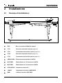
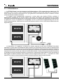
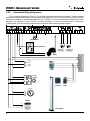
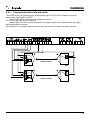
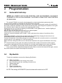
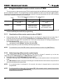
ITALIANO
PCM412
Centrale di automazione
per cancello ad ante
MANUALE UTENTE
PCM412 - Manuale per l'utente
Norme generali per la sicurezza
!
!
!
!
!
!
!
!
!
!
!
!
!
!
!
!
!
2
Leggere attentamente le istruzioni prima di iniziare I'installazione del prodotto e conservarle per riferimenti futuri.
Installazione, collegamenti elettrici e regolazioni devono essere effettuati nell'osservanza delle norme di buona
tecnica e di sicurezza vigenti (EN12453).
HILTRON Srl non è responsabile dell'inosservanza della buona tecnica nella costruzione dei cancelli da motorizzare,
nonchè delle deformazioni che dovessero intervenire nell'utilizzo.
Questo prodotto è stato progettato e costruito esclusivamente' per I'utilizzo indicato in questa documentazione.
Qualsiasi altro utilizzo non espressamente indicato potrebbe pregiudicare I'integrità del prodotto e/o rappresentare
fonte di pericolo.
HILTRON Srl declina qualsiasi responsabilità derivata dall'uso improprio o diverso da quello per cui I'automatismo è
destinato.
Non utilizzare I'apparecchio in atmosfera esplosiva: presenza di gas o fumi infiammabili costituiscono un grave
pericolo per la sicurezza.
Prima di effettuare qualsiasi intervento sull'impianto togliere I'alimentazione elettrica.
Prevedere sulla rete d'alimentazione dell'automazione un interruttore onnipolare con distanza d'apertura dei contatti
uguale o superiore a 3 mm. In alternativa e consigliabile I'uso di un magnetotermico da 6A con interruzione
onnipolare.
Verificare che a monte dell'impianto elettrico vi sia un interruttore differenziale con soglia da 0,03 A.
Verificare che I'impianto di terra sia realizzato a regola d'arte e collegarvi iI cancello. Collegare inoltre a terra il filo
Giallo/Verde dell'automatismo.
L'utente utilizzatore deve astenersi da qualsiasi tentativo di riparazione o d'intervento diretto e rivolgersi solo a
personale qualificato.
Per la manutenzione utilizzare esclusivamente parti originali della HILTRON Srl. Non eseguire alcuna rnodifica sui
cornponenti facenti parte il sistema d'autornazione. I materiali dell'imballaggio (plastica, cartone, ecc.) non devono
essere lasciati alla portata dei bambini in quanto potenziali fonti di pericolo.
L'installatore deve fornire tutte le informazioni relative al funzionamento manuale del sistema in caso d'emergenza e
consegnare all'utente utilizzatore dell'impianto il presente libretto d'avvertenze allegato al prodotto.
L'automazione dispone di una sicurezza antischiacciamento costituita da un controllo di coppia che, se tarato
correttamente, è estremamente sicuro ed affidabile.
In ogni caso HILTRON Srl prescrive sempre I'installazione di altri dispositivi di sicurezza, tenendo in considerazione le
normative in vigore, I'ambiente di installazione, la logica di funzionamento del sisterna, le dimensioni e il peso della
struttura da automatizzare.
I dispositivi di sicurezza (es.: fotocellule, coste pneumatiche, etc...) permettono di proteggere eventuali zone di
schiacciamento, convogliamento ed in generale di pericolo, dell'automazione. Per ogni irnpianto è indispensabile
I'utilizzo di almeno una segnalazione luminosa (es.: art. LAMP12FG) nonchè di una targa di segnalazione (es.: art.
TRG) fissato adeguatamente alla struttura del cancello.
HILTRON Srl declina ogni responsabilità ai fini della sicurezza e del buon funzionamento dell'automazione nel caso in
cui vengano utilizzati componenti dell'impianto diversi da quelli prodotti da HILTRON Srl.
Introduzione
Indice
Capitolo 1
Introduzione
4
1.1 Descrizione della centrale .................................................................................4
1.2 Caratteristiche tecniche.....................................................................................4
Capitolo 2
Installazione
5
2.1 Esempio di installazione....................................................................................5
2.2 Collegamenti .....................................................................................................6
2.2.1 Alimentazione ........................................................................................7
2.2.2 Comandi di STOP e apertura.................................................................8
2.2.3 Collegamento fotocellule a rele..............................................................9
Capitolo 3
Programmazione
10
3.1 Finecorsa automatici .......................................................................................10
3.2 Dip-switch ........................................................................................................10
3.2.1 Modi di funzionamento .........................................................................11
3.2.2 Tempo di sfasamento...........................................................................13
3.2.3 Colpo di ariete......................................................................................13
3.2.4 Tipo di lampeggiatore ..........................................................................13
3.2.5 Anta singola o doppia ..........................................................................13
3.2.6 Tipo di fotocellule .................................................................................13
3.3 Programmazione ricevitore per telecomando TWIN .......................................14
3.1
Visualizzazione del codice programmato sulla centrale ......................14
3.2
Acquisizione codice telecomando TWIN con auto-apprendimento .....14
3.3
Memorizzazione di un nuovo codice nel telecomando TWIN ..............15
3.4
Visualizzazione di un codice esistente nel telecomando TWIN ...........15
3.5
Sostituzione batteria ............................................................................15
Capitolo 4
Manutenzione
16
4.1 Cancello ..........................................................................................................16
4.2 Fusibili .............................................................................................................16
3
PCM412 - Manuale per l'utente
1
Introduzione
1.1
Descrizione della centrale
La PCM412 e’ una centrale di automazione per cancelli ad una o due ante, alimentata a batterie, in
grado di pilotare motoriduttori a 12V, con un sistema automatico di riconoscimento dei fine-corsa e di
arresto in caso di ostacolo.
Sulla centrale e’ integrato un decodificatore per i telecomandi TWIN a doppio canale con
autoapprendimento dei codici per comandare l’apertura totale o parziale (solo un’anta) che si avvale di un
ricevitore tipo BIRD ed inoltre sono presenti due pulsanti per il comando manuale della centrale e per
l’apprendimento dei codici del telecomando.
Le logiche di funzionamento sono selezionabili tramite dip-switch e consentono le modalita’:
condominiale;automatica;passo-passo con richiusura automatica e passo-passo con stop. Le altre
funzioni selezionabili con i dip-switch sono il termpo di sfasamento delle due ante in chiusura , l’attivazione
del colpo di ariete per lo sgancio dell’elettroserratura la selezione del tipo di cancello ad anta singola o
doppia anta e del tipo di fotocellula.
Due trimmer regolano il tempo di spinta prima di arrestare il movimento in caso di ostacolo e la pausa
nelle modalita’ automatiche prima della chiusura del cancello.
Sulla scheda sono inoltre presenti i LED che segnalano lo stato degli ingressi (START1,START2,
STOP, Fotocellula di apertura e di chiusura), nonche’ per la carica delle batterie, per il riconoscimento del
modo dei due motoriduttori, per l’inversione del collegamento alle batterie e uno di segnalazione errori. E’
anche presente in morsettiera un’uscita per il pilotaggio di una segnalazione in caso di mancanza o di
inefficienza delle batterie.
1.2
!
!
!
!
!
!
!
!
!
!
!
!
!
!
!
!
!
!
!
!
!
!
!
4
Caratteristiche tecniche
Tensione nominale di alimentazione: 230 Vac 50 Hz +/- 5%
Batterie: 2x 12 Vcc 7-18 Ah
Consumo solo scheda: 7mAca @ 230Vca oppure 18mA @ 24Vcc
Ingresso pannello solare 24Vcc per ricarica batterie
Uscita servizi: 24Vcc 400mA continui, 2Ah max
Uscita segnalatore luminoso: 24Vcc 25W
Uscita per elettroserratura
Uscita Open collector max 15mA, 45V per indicare lo stato di carica della batteria
Ricarica batterie ad impulsi sia da rete che da pannello solare con controllo della corrente per
regolare la durata degli impulsi e controllo di tensione per rilevarne la carica.
Controllo e segnalazione inversione polarita’ batterie
Gestione per fotocellule tipo tradizionale a rele’ o ad impulsi con auto-diagnosi
Decoder telecomandi integrato ed interfaccia per antenna BIRD
Tempo di pausa per la richiusura: da 1 a 65 secondi regolabili con trimmer
Funzionamento su cancelli a una o due ante
Comandi per apertura totale(entrambe le ante) o parziale(solo un’anta)
Tempo di sfasamento richiusura ante: 4 o 8 secondi
Funzione colpo d’ariete escludibile per lo sblocco elettroserratura
Fusibile sul primario del trasformatore:cilindrico 5x20 ritardato 500mA/250V
Fusibile F1 alimentazione rete: cilindrico 5x20 rapido 8A/250V
Fusibile F2 alimentazione generale: cilindrico 5x20 rapido 8A/250V
Fusibile F3 alimentazione servizi: cilindrico 5x20 rapido 3.15A/250V
Motoriduttori 12Vcc/50W
Trasformatore toroidale 80VA
Installazione
2
Installazione
2.1
Esempio di installazione
9
11
10
2
3
6
7
1
8
4
5
1
BOX
Box con centrale PCM412 e batterie
2
FTC1
Ricevitore fotocellula esterna (pagina 9)
3
FTC1
Trasmettitore fotocellula esterna (pagina 9)
4
FTC2
Ricevitore fotocellula interna (pagina 9)
5
FTC2
Trasmettitore fotocellula interna (pagina 9)
6
SERRATURA
Elettroserratura montata su ANTA1
7
MOTORE2
Motoriduttore a 12V montato su ANTA2
8
MOTORE1
Motoriduttore a 12V montato su ANTA1
9
STOP/START
Selettore a chiave SC1
10
LAMPG
Segnalatore luminoso LAMPG24FG
11
BIRD
Antenna ricevitore VHF BIRD
11
11
5
PCM412 - Manuale per l'utente
2.2 COLLEGAMENTI
25
1 2 3 4 5 6 7
1
2
3
4
5
6
7
8
9
10
11
12
13
14
15
16
17
18
19
20
21
22
23
24
25
6
COM
STOP
START 1
START 2
OUT MON
BIRD 2
BIRD 1
FTC 1
COM
FTC 2
- Lamp 24Vdc
+ Lamp 24Vdc
COM GND
+ 24 Serr
+ 24 Ftc
+ 24 Vdc
- Pann. Solare
+ Pann. Solare
MOTORE 1
MOTORE 1
MOTORE 2
MOTORE 2
+
8 9 10 11 12 13 14 15 16 17 18
19 20
21 22
23
24
Contatto comune di massa
Ingresso comando di stop (NC)
Ingresso comando di apertura totale (NA)
Ingresso comando di apertura parziale (NA)
Uscita monitor batteria funzionante e carica
Ingresso contatto 2 antenna BIRD
Ingresso contatto 1 antenna BIRD
Ingresso per fotocellule interne apertura
Contatto comune per fotocellule
Ingresso per fotocellule esterne di chiusura
Contatto per segnalatore luminoso(-)
Contatto per segnalatore luminoso(+)
Contatto negativo alimentazione comune
Uscita positivo per elettrosserratura
Uscita positivo alimentazione fotocellule tradizionali
Uscita positivo alimentazione supplementare
Ingresso per negativo pannello solare
Ingresso per positivo pannello solare
Contatto motore
Contatto motore
Contatto motore
Contatto motore
Ingresso per negativo batterie
Ingresso per positivo batterie
Connettore per il trasformatore toroidale di alimentazione 230Vac
Installazione
2.2.1 Alimentazione
La PCM412 basa il suo funzionamento sull’alimentazione a 24V erogata da due batterie da 12V
collegate in serie; i motori a 12Vcc vengono alimentati mediante una sezione step-down che consente di
avere sempre una tensione efficiente di 12V, per garantire il funzionamento anche in condizioni critiche
(mancanza di rete e batterie scariche).
Le batterie sono costantemente mantenute in carica dalla rete elettrica 230Vac mediante il
trasformatore toroidale ed un circuito interno che carica “ad impulsi” per migliorare la loro durata.
Prevedere sulla rete di alimentazione un interruttore onnipolare con distanza d’apertura dei contatti uguale
o superiore a 3 mm. In alternativa è consigliabile l’uso di un interruttore magnetotermico da 6 A con
interruzione onnipolare. Verificare che a monte dell’impianto elettrico vi sia un interruttore differenziale con
soglia da 0.03A.
B12V7A
B12V7A
Sezionatore
230V~
50Hz
In alternativa, o in aggiunta, la ricarica può essere operata da una serie di pannelli fotovoltaici
mediante il circuito interno di limitazione della corrente e di controllo del livello di carica. Si presta quindi
anche ad installazioni su varchi ove non sia presente la rete elettrica, e dimensionando opportunamente la
corrente delle batterie e dei pannelli solari può garantire i necessari cicli di apertura e chiusura. In caso di
mancanza di corrente di rete, per evitare la scarica delle batterie, l’uscita di alimentazione delle fotocellule
e’ attivata solo prima di mettere il cancello in movimento. In mancanza di rete elettrica, infine, per evitare di
danneggiare le batterie laddove siano scariche oltre la soglia minima (9V cad.), il cancello non viene
messo in movimento automaticamente e sarà necessario operare l’apertura manualmente.
B12V7A
B12V7A
7
PCM412 - Manuale per l'utente
2.2.2
Comandi di Stop ed Apertura
Per il comando di Apertura (Start 1 e 2) e lo Stop utilizzare la connessione illustrata. Possono essere
realizzati con pulsanti meccanici, con chiavi elettroniche (tipo Sk103), con chiavi di prossimità (tipo PX100),
utilizzando l’uscità di un combinatore telefonico (tipo TDC26) o con una combinazione degli stessi posti in
parallelo. Per utilizzare il timer di blocco occorre impostare il modo di funzionamento in Automatico
Condominiale: in questo modo il persistere del comando su Start1 lascia il cancello aperto.
LAMP24FG
MONITOR
BATTERIE
K
A
M
ON
OFF
M
MOTORIDUTTORE 1*
GEARED MOTOR 1 *
12V~ 700W max
MOTORIDUTTORE 2*
GEARED MOTOR 2 *
12V~ 700W max
BIRD
Apertura
Parziale
PXRE
A
B
C
Apertura
Totale
PX100
NA
APRE
CHIUDE
NC
STOP
A
B
C
COLPX
Timer *
N.A.
TDC28
C
NA
COL100PX
8
PXR
Installazione
2.2.3
Collegamento Fotocellule a relè
La PCM412 puo' utilizzare fotocellule con autodiagnosi tipo FX30\FX30D oppure tradizionali con
uscita a rele' tipo FX40D o FX55D .
Selezionando lo switch 8 si programma il tipo ti fotocellule.
Non e possibile utilizzare entrambi i tipi di fotocellule insieme.
Posizionare i due TX sullo stesso lato del cancello ( es sinistra, una internamente e l'altra all'esterno) e i
due RX sul lato opposto ( es. destra, una internamente e l'altra all'esterno) e programmare i differenti
canali. Se la centrale è alimentata da pannelli solari, le fotocellule si accenderanno solo al momento
dell'attivazione del cancello.
2
-
3
24V
24V
+
+
NC
FX40D / FX55D
TX
RX
5
-
4
24V
24V
-
+
+
NC
FX40D / FX55D
RX
TX
9
PCM412 - Manuale per l'utente
3
Programmazione
3.1
Fine-corsa automatici
NOTA: TUTTE LE VOLTE CHE LA CENTRALE VIENE ALIMENTATA, VIENE
EFFETTUATO SEMPRE UN CICLO DI APERTURA/CHIUSURA PER
MEMORIZZARE LA POSIZIONE DEI FINE-CORSA.
La centrale PCM412 non necessità di contatti di fine corsa di tipo elettromagnetici o elettromeccanici;
per il corretto funzionamento dell’impianto, occorre però memorizzare la corsa del cancello per il
riconoscimento dei fine corsa; questa operazione consente sia di determinare i punti in cui procedere con il
rallentamento del movimento della ante, sia di riconoscere la posizione del cancello quando l’anta è ferma
da un ostacolo che impedisce il normale ciclo di apertura-chiusura.
La centrale PCM412 conta il numero di rotazioni dei motori per conoscere la posizione del cancello e
durante il conteggio procede con l’accensione dei due LED ADJM1 per il motore 1 e ADJM2 per il motore
2. Raggiunto una posizione vicina al termine del movimento i motori sono rallentati e lasciano che il
cancello si avvicini al fine corsa a velocità ridotta. Quando il cancello incontra un ostacolo che lo ferma,
controlla il contatore di rotazioni: se è sufficentemente prossimo al valore atteso per il fine corsa considera
il blocco come fine corsa, altrimenti lo riconosce come ostacolo.
Alla prima accensione della centrale o ad ogni accensione dopo un distacco delle alimentazioni, la
centrale esegue un ciclo completo di apri, richiudi e memorizza il numero di rotazioni del motore durante
l’intero movimento di chiusura.
Dopo aver ultimato l’impianto portare le due ante in una posizione intermedia sbloccando i due
motoriduttori avvalendosi dell’apposita chiave di sblocco e procedere poi con il serraggio.
Collegare quindi le batterie alla centrale e dare un comando qualunque di apertura o con un
telecomando o con un comando meccanico tipo Sc1 oppure agendo direttamente su uno dei pulsanti P1 o
P2 sul circuito.
Verificare che durante questa operazione non vi siano ostacoli meccanici che impediscano la
corretta misurazione del movimento. Raggiunta la chiusura delle due ante il numero di rotazione è
memorizzato nella centrale. La centrale ha inoltre un sistema che con l’andar del tempo corregge eventuali
piccole variazioni del conteggio dovute all’usura o alla dilatazione termica e quindi non necessita di
ripetere l’operazione, finchè l’alimentazione rimane presente. Se però si procede allo sblocco meccanico
del motoriduttore e al movimento manuale del cancello, occorre ripetere l’auto apprendimento dei fine
corsa togliendo le alimentazioni alla centrale e poi ripristinandole.
3.2
Dip-Switch
Per mettere in funzione l’impianto bisogna impostare i seguenti Dip-Switch:
1-2
3
4
5
6
7
8
Modo di funzionamento
Tempo di sfasamento per la chiusura delle due ante
Colpo d’ariete (per lo sblocco dell’elettroserratura)
Tipo di lampeggiatore impiegato
NON UTILIZZATO
Anta doppia o singola
Tipo di fotocellule impiegate
NOTA: Il settaggio dei DIP- SWITCH va fatto a centrale spenta.
10
Programmazione
3.2.1
Modi di funzionamento
La centrale PCM412 ha 4 diverse logiche di funzionamento selezionabili con i Dip-Switch 1 e 2.
ON
1
2
3
4
5
6
7
8
STATO DEL
CANCELLO
CHIUSO
IN
APERTURA
Passo passo con stop
START 1
Apre ed attende
successivo
comando.
START 2
Apre solo anta1 e
richiude dopo la
pausa
Ferma il cancello; il Ferma il cancello; il
successivo comando successivo comando
lo richiude.
lo richiude.
APERTO
Richiude
Richiude
IN CHIUSURA
Ferma il cancello; il
successivo
comando lo riapre.
Ferma il cancello; il
successivo comando
lo riapre
STOP
FTC. Interna
FTC. Esterna
Impedisce l’apertura
Impedisce l’apertura
Impedisce l’apertura
Ferma il cancello ed
al ripristino attende
ulteriore comando di
start per continuare
l’apertura.
Ferma il cancello; al
disimpegno riprende
l’apertura
Nessun effetto
Blocca il cancello
Blocca il cancello
Blocca il cancello
aperto. Al ripristino aperto. Al disimpegno
aperto. Al
attende un
attende il comando di disimpegno attende
successivo comando
comando di start.
start.
Ferma il movimento
ed al ripristino
attende ulteriore
comando per la
chiusura
Ferma il cancello e
riapre al disimpegno
Ferma il cancello e
riapre
immediatamente il
cancello.
ON
1
2
3
4
5
6
7
8
STATO DEL
CANCELLO
Passo passo con richiusura automatica
START 1
START 2
STOP
FTC. Interna
FTC. Esterna
Apre solo anta1 e
richiude dopo la
pausa
Impedisce l’apertura
Impedisce l’apertura
Impedisce l’apertura
Ferma il cancello ed
Arresta il movimento. al ripristino attende
Un successivo
ulteriore comando di
comando richiude
start per continuare
entrambe le ante.
l’apertura.
Ferma il movimento.
Al disimpegno
riprende l’apertura
Nessun effetto
CHIUSO
Apre e richiude dopo
la pausa
IN
APERTURA
Arresta il moto. Un
successivo comando
avvia la richiusura.
IN
PAUSA
Azzera la pausa e
richiude
immediatamente
Azzera la pausa e
richiude
immediatamente
Lascia il cancello
aperto. Al ripristino
chiude senza
attendere la pausa
Impedisce la
richiusura. Al
disimpegno chiude
immeditamente
Impedisce la
richiusura
IN CHIUSURA
Arresta la chiusura.
Un successivo
comando avvia la
riapertura
Arresta la chiusura.
Un successivo
comando avvia la
riapertura
Ferma il movimento
ed al ripristino
attende ulteriore
comando per la
chiusura
Ferma il cancello e
riapre al disimpegno
Ferma il cancello e
riapre
immediatamente
NOTA: Un comando di start1 durante un ciclo di apertura parziale non mette mai in movimento la seconda
anta. Un comando di start2 durante un ciclo di apertura totale ha effetto su entrambe le ante. Per passare
da una apertura parziale ad una totale o viceversa è necessario far ripartire il cancello dalla posizione di
chiuso.
11
PCM412 - Manuale per l'utente
ON
1
2
3
4
5
6
7
8
Automatico
STATO DEL
CANCELLO
START 1
START 2
STOP
FTC. Interna
FTC. Esterna
CHIUSO
Apre e richiude dopo
la pausa
Apre solo anta1 e
richiude dopo la
pausa
Impedisce l’apertura
Impedisce l’apertura
Impedisce l’apertura
IN
APERTURA
Ferma l’apertura e
richiude
immediatamente
Ferma l’apertura e
richiude
immediatamente
entrambe le ante
Ferma il cancello ed
al ripristino attende
ulteriore comando di
start per continuare
apertura
Ferma il movimento.
Al disimpegno
riprende l’apertura
Nessun effetto
IN
PAUSA
Nessun effetto
Nessun effetto
Lascia il cancello
aperto. Al ripristino
chiude senza
attendere la pausa
Impedisce la
richiusura
Impedisce la
richiusura
Ferma il movimento
ed al ripristino
attende ulteriore
comando per la
chiusura
Ferma il cancello e
riapre al disimpegno
Ferma il cancello e
riapre
immediatamente
IN CHIUSURA
Arresta la chiusura e Arresta la chiusura e
riapre
riapre
immediatamente
immediatamente
ON
1
2
3
4
5
6
7
8
Automatico condominiale
STATO DEL
CANCELLO
START 1
START 2
STOP
FTC. Interna
FTC. Esterna
CHIUSO
Apre e richiude dopo
la pausa
Apre solo anta1 e
richiude dopo la
pausa
Impedisce l’apertura
Impedisce l’apertura
Impedisce l’apertura
IN
APERTURA
Continua apertura
Continua apertura
Ferma il cancello. E
aspetta il comando
start per continuare
l’apertra
Ferma il movimento.
Al disimpegno
riprende l’apertura
Nessun effetto
IN
PAUSA
Prolunga la pausa
fino al rilascio
Nessun effetto
Impedisce la
richiusura
Impedisce la
richiusura
Ferma il cancello e
riapre al disimpegno
Ferma il cancello e
riapre
immediatamente
IN CHIUSURA
12
Arresta la chiusura e Arresta la chiusura e
riapre
riapre
immediatamente
Lascia il cancello
aperto. Al ripristino
chiude non aspetta
la pausa
Ferma il movimento
ed al ripristino
attende ulteriore
comando per
chiusura
Programmazione
3.2.2
Tempo di sfasamento
E' possibile regolare l’intervallo fra la chiusura della seconda anta (quella spinta dal motoriduttore
2, senza elettroserratura, che apre per seconda) rispetto alla prima. Un maggiore tempo di sfasamento
può risultare utile quando la corsa della prima anta in chiusura è molto inferiore della seconda, per
evitare che arrivi per prima a fine corsa con un errato accavallamento,e Impostando il pulsante 3 in
una delle posizioni indicate in figura è possibile regolare l'intervallo di chiusura della seconda anta
(spinta dal motoriduttore 2, senza elettroserratura) rispetto alla prima. Questo risulta molto utile
quando la prima anta chiude lentamente per evitare un accavallamento errato a fine corsa.
ON
ON
1
2
3
4
5
6
3.2.3
7
8
1
Sfasamento di 4 secondi
2
3
4
5
6
7
8
Sfasamento di 8 secondi
Colpo d’ariete
Il colpo d’ariete è utile per sbloccare l’elettroserratura quando si avvia l’apertura del cancello. Per
fare questo la prima anta con l’elettroserratura viene spinta dal motoriduttore per alcuni istanti in
chiusura, prima di iniziare il movimento di apertura. Con l’interruttore 4 del dip switch in ON si attiva
questa funzione.Posizionando il pulsante 4 come illustrato “Colpo d'ariete attivo”, l'apertura del
cancello sarà effettuata con una spinta (della durata di alcuni istanti) in chiusura del motoriduttore
sull'anta che riporta l 'elettroserratura garantendo cosi l'apertura della stessa.
ON
ON
1
2
3
4
5
6
3.2.4
7
8
1
Colpo d'ariete disattivo
2
3
4
5
6
7
8
Colpo d'ariete attivo
Lampeggiatore
Mediante il dip-switch 5, l'uscita del lampeggiatore può essere impostata sia fissa, per utilizzare
lampeggiatori tradizionali, o ad intermittenza, per lampade stroboscopiche
ON
ON
1
2
3
4
5
6
3.2.5
7
8
Uscita fissa
1
2
3
4
5
6
7
8
Uscita lampeggiante
Anta doppia o singola
Selezionando il pulsante 7 nelle posizioni indicate è possibile attivare il funzionamento di un
singolo motore per una anta o tutti e due i motori per un cancello a doppia anta.
ON
ON
1
2
3
4
5
6
3.2.6
7
8
Anta doppia
1
2
3
4
5
6
7
8
Anta singola
Tipo di fotocellule
La centrale PCM412 può utilizzare sia le fotocellule tradizionali a relè tipo FX40D / FX55D che le
fotocellule ad impulsi con autodiagnosi tipo FX30D.Impostando il pulsante 8 nelle posizioni indicate in
figura è possibile impostare le diverse tipologie di fotocellule.In assenza di alimentazione per le
batterie, le fotocellule sono disattivate a cancello chiuso ed alimentate solo prima di mettere in moto il
cancello.
Questa operazione comporta un piccolo ritardo fra il comando e l'avvio del moto del cancello.
ON
ON
1
2
3
4
5
6
7
8
FX40D / FX55D
1
2
3
4
5
6
7
8
FX30D
13
PCM412 - Manuale per l'utente
3.3
Programmazione ricevitore per radiocomando TWIN
I due tasti del telecomando TWIN possono essere memorizzati con due codici diversi corrispondenti
ai due canali A e B. La programmazione deve essere ripetuta per ogni uno dei due tasti del radiocomando.
Per accedere alla programmazione è necessario premere entrambi i tasti per alcuni secondi, finchè il
LED rimane acceso;di seguito e riportato un riepilogo dei tempi di accesso al setup:
0 sec.
2 sec.
5 sec.
Stato dei LED
LED “1” e “2”
spenti
LED “1” e “2”
accesi fissi
LED “1” e “2”
lampeggianti
Funzione
Nessun effetto.
Rilasciando P1 e P2, si
entrerà in modalità di
visualizzazione del
codice.
Rilasciando P1 e P2, si
entrerà in modalità
autoapprendimento del
codice.
NOTA:durante la programmazione, se non si preme alcun tasto per almeno 5 secondi il LED si
spegne e la fase di programmazione termina automaticamente
3.1
!
!
!
Visualizzazione del codice programmato sulla centrale
Premere contemporaneamente i pulsanti P1-P2 (pagina 6) per almeno 2 secondi e non
più di 5 secondi, finchè i due LED “Start1” e “Start2” non si accenderanno fissi
Premendo il pulsante P1 verrà visualizzato il codice a 12 bit del canale "A" tramite una
sequenza di lampeggi dei due LEDs:
!
un lampeggio del LED “Start1” indica dip switch ON
!
un lampeggio del LED “Start2” indica dip switch OFF
Terminata la sequenza si uscirà automaticamente dalla fase di programmazione
NOTA: Per visualizzare il codice del canale "B", ripetere la procedura utilizzando il pulsante
P2.
3.2
!
!
!
!
Acquisizione codice del telecomandoTWIN con auto-apprendimento
Premere contemporaneamente i pulsanti P1-P2 (pagina 6) per almeno 5 secondi, finchè i
due LED “Start1” e “Start2” non iniziano a lampeggiare
Premere il pulsante P1, lampeggerà solo il “Start1”
Durante il lampeggio, premere entro 5 secondi il pulsante "A" del telecomando per fare
acquisire il codice.
Il “Start1” emetterà una serie di lampeggi per indicare l'avvenuta acquisizione e si uscirà
automaticamente dalla fase di programmazione
NOTA: Per far acquisire il codice del canale "B" del telecomando, ripetere la procedura,
utilizzando il pulsante P2 ed il LED “Start2”
14
Programmazione
3.3
Memorizzazione di un nuovo codice nel telecomando TWIN
Per accedere all'inserimento di un nuovo codice:
!
!
!
!
!
!
!
*
Entrare in programmazione tenendo premuti i due tasti del TWIN per alcuni secondi finchè il led
rimane acceso
Digitare la sequenza di tasti "1" - "1" - "0" - "0"
Inserire le 10 cifre del codice utilizzando:
!
“0” (tasto destro): ossia dip-switch "OFF" sulle versioni TWIN precedenti*
!
“1” (tasto sinistro): ossia dip-switch "ON" sulle versioni TWIN precedenti*
Ad ogni inserimento il LED si spegnerà per un istante.
Inserire le 2 cifre del canale:
!
Canale A"1" - "0": ossia tasto sinistro sulle versioni TWIN precedenti
!
Canale B"1" - "1": ossia tasto destro sulle versioni TWIN precedenti
Premere il pulsante a cui assegnare il codice appena inserito (A oppure B).
Il LED si spegne alla fine della programmazione.
Ad esempio, per programmare un codice o duplicare un TWIN di precedente versione che abbia i dipswitch così impostati:
1
2
3
4
5
6
7
8
9
10
ON
OFF
è necessario digitare la seguente sequenza di tasti:
3.4
1 1 0 0
accesso
1 0 0 1 1 0 1 0 0 1
codice
1 0 (lamp. veloce del LED) 1
canale A
assegn. al tasto sinistro
1 1 0 0
accesso
1 0 0 1 1 0 1 0 0 1
codice
1 1 (lamp. veloce del LED) 0
canale B
assegn. al tasto destro
Visualizzazione di un codice esistente nel telecomando TWIN
Per leggere il codice programmato:
!
!
!
!
3.5
Entrare in programmazione tenendo premuti i due tasti per alcuni secondi finchè il led rimane
acceso
Digitare la sequenza di tasti "1" - "0" - "1" - "0"
Premere il tasto di cui si desidera conoscere il codice (A oppure B)
Il LED si spegne e poi comincia ad emettere una serie di dodici lampeggìi:
!
un lampeggìo breve indica "0"
!
un lampeggìo lungo indica "1”
Sostituzione batteria
Svitare la vite posta sul fondo del telecomando per aprire il contenitore, togliere la vecchia batteria ed
inserirne una nuova rispettando le polarità indicate sul contenitore.
Controllare il corretto funzionamento dei due tasti prima di richiudere il contenitore.
15
PCM412 - Manuale per l'utente
4
Manutenzione
4.1
Cancello
Eseguire controlli periodici sulla struttura del cancello ed in particolare verificare la perfetta
condizione dei carrelli, delle cerniere, della elettroserratura e delle parti meccaniche soggette ad usura.
4.2
F1
F2
F3
Fusibili
8A 250V
8A 250V
3,5A 250V
®
PROGETTAZIONI E PRODUZIONI ELETTRONICHE
Azienda con Sistema di
gestione per la Qualità
UNI EN ISO 9001:2000
DICHIARAZIONE DI CONFORMITA’
COSTRUTTORE:
HiLTRON S.r.l.
INDIRIZZO:
Strada Provinciale di Caserta , 218 - 80144 - NAPOLI
Sulla valutazione di prove eseguite su impianti campioni rispecchianti la configurazione funzionale prevista
per l'utilizzazione, risulta che i prodotti:
CODICE DEI PRODOTTI:
PCM412
DESCRIZIONE DEI PRODOTTI:
CENTRALE PER AUTOMAZIONE
I SUDDETTI PRODOTTI SODDISFANO LE DIRETTIVE
RIPORTATE IN TABELLA CON RIFERIMENTO ALLE NORME COMUNITARIE.
DIRETTIVE
RAEE
MARCHIO UTILIZZATO:
Lead free
Pb
RoHS
compliant
NORME DI RIFERIMENTO
EMC 2006/95/CE
EN50081-1 ; norma generica di emissione
EN50082-1 ; norma generica di immunità
EMC 2004/108/CE
EN60065 ; norma per la sicurezza delle apparecchiature elettriche
collegate alla rete d’uso domestico e analogo uso similare
CONFORMITA’ RoHS
Dichiarazione di conformità alle limitazioni dell’uso di sostanza pericolose regolamentate dalla direttiva
2002/95CE (RoHS) recepita con D.lgs 25 Luglio 2005 n°151 (Articolo 5).
Il prodotto è conforme alle disposizioni della direttiva su indicata sulle restrizioni all’uso di alcune sostanze pericolose
nelle apparecchiature elettriche ed elettroniche,ovvero non le contengono in concentrazioni superiori ai margini previsti.
CONFORMITA’ RAEE
In alcuni paesi dell’Unione l prodotto non ricade nel campo di applicazione della legge nazionale
di recepimento della direttiva WEEE, e quindi non è in essi vigente
alcun obbligo di raccolta differenziata a fine vita
DATA
L’AMMINISTRATORE DELEGATO
01 Gennaio 2010
16
Prodotto da
ENGLISH
PCM412
Automation central unit
for hinged gate
USER MANUAL
PCM412 - User Manual
Important Safeguards
!
!
!
!
!
!
!
!
!
!
!
!
!
!
!
!
!
!
Please read this manual thoroughly before installation and keep it for future reference.
Installation, electrical connections and adjustements must comply with technical and safety standards in
force.(EN12453).
HILTRON Srl cannot be held responsible for failure to observe technical standards in the construction of gates, or for any
deformation of gates which may occur during use.
This product has been designed and manufactured only for the use stated in this manual. Any other use not expressly set
forth will affect the reliability of the product and/or could be source of hazard.
HILTRON Srl cannot be held responsible for any damage caused by improper use or different from the use for wich the
autamtion system is destined to.
Do not use this device in areas subject to explosion: the presence of flammable gas or fumes is a serious hazard.
Before carrying out any operations, turn off the system’s main switch.
An omnipower switch shall be provided for the installation with an opening distance of the contacts of 3 mm or more.
Alternativel, use a 6A thermomagnetic breaker with a multi-pole switching.
Ensure that there is a differential switch up-line of the electrical system, with a trip threshold of 0.03A.
Check that the earthing plant is in perfect condition and connect it to the metallic parts. Also earth the Yellow/Green wire of
the operator.
The end-user must avoid any attempt to repair or adjust the automation personally. These operations must be carried out
only by qualified personnel.
For maintenance operations, use only original spare parts produced by HILTRON Srl. Do not carry out any modifications
to automation components. Packaging materials (plastic, cardboard, etc.) are a potential hazard and must be kept out of
reach of children.
The installer must supply all informations regarding manual operation of the system in the event of an emergency and
provide the end-user with this manual attached to the product.
The automation is fitted with an anti-crush safety system that is a torque control device.
In any case, HILTRON Srl suggests the installation of others safety devices, in accordance with standards in force,
system operating logic and weight and dimension of the gate.
The safety devices (i.e.: photocells, pneumatic edges, etc...) protect areas wherethere is a mechanical movement hazard
(i.e.: crushing, entrapment and cutting).
Each installation must be fitted with at least one flashing light (i.e.: item LAMP12FG) or with at signalling plate (i.e.: item
TRG) fixed to the gate.
HILTRON Srl cannot be held responsible regarding safety and correct operation of the automation in the event that parts
other than original parts produced by HILTRON Srl.
18
Introduction
Contents
Chapter 1
Introduction
20
1.1 Description of central unit ...............................................................................................20
1.2 Technical Features..........................................................................................................20
Capitolo 2 Installation
21
2.1 Example of in stallation...................................................................................................21
2.2 Connections....................................................................................................................22
2.2.1 Alimentation .......................................................................................................23
2.2.2 Controls of Stop and Opening............................................................................24
2.2.3 Connections photocells with relais.....................................................................25
2.3 Connections photocells with relais..................................................................................11
Capitolo 3 Programmation
26
3.1 Automatic limit stop.........................................................................................................26
3.2 Dip-Switch.......................................................................................................................26
3.2.1 Mode of functionnement ....................................................................................27
3.2.2 Closing wing timing ............................................................................................29
3.2.3 Door hummering ................................................................................................29
3.2.4 Warning light ......................................................................................................29
3.2.5 Double or single door.........................................................................................29
3.2.6 Type of photocells ..............................................................................................29
3.3 Programmation remote control receiver TWIN ...............................................................30
3.3.1 Visualization of the remote control code on PCM412 ........................................30
3.3.2 Auto learning of the remote control code ...........................................................30
3.3.3 Programmation of a new code in TWIN .............................................................31
3.3.4 Visualization of existing code in TWIN remote control .......................................31
3.3.5 Battery replacement...........................................................................................31
4
Maintenance ...................................................................................................................32
4.1 Gate
...........................................................................................................................32
4.2 Fuses ...........................................................................................................................32
19
PCM412 - User Manual
1
Introduction
1.1
Description of central unit
The PCM412 is an automation central unit for hinged gates for one or two doors, powered by
batteries, capable of driving 12V geared-motors, with automatic recognition of limit-stop and
stop in case of obstacle.
On the central is integrated a decoder for Dual Channel TWIN remote control, with
teach the codes to control the total or partial opening (one door only) that uses a
BIRD receiver type and there are also two buttons for manual control of the central and
learning of remote control codes.
The operating modes are selectable with DIP switches and allow the condominium mode automatic;
step by step with automatic reclosing and step by step with stop. Other
functions available with the DIP switches are the closing wing time of the two doors closed, the activation
hammering to release solenoid lock,the selection for gate type with single or double doors and the
photocell type.
Two trimmers regulate the time of thrust before stopping the movement in case of obstacle and pause
in automatic mode 'before the closure gate
T h e b o a r d a l s o h a s L E D s t h a t i n d i c a t e i n p u t s t a t u s ( S TA RT 1 , S TA RT 2 ,
STOP photocell opening and closing), as well as' the charge battery, the recognition of
two ratiomotors, the reversing connection to the batteries and an error report.
Also is present in terminal board output for driving an alert in case of absence or
inefficiency of the batteries.
1.1
!
!
!
!
!
!
!
!
!
!
!
!
!
!
!
!
!
!
!
!
!
!
!
20
Technical Features
Power supply voltage: 230 Vac 50 Hz + / - 5%
Batteries: 2x 12 Ah 7-18 Vdc
Consumption only board: 7mAca @ 230VAC or 24VDC @ 18mA
Input 24VDC solar panel to recharge batteries
Services output: 400 mA continuous 24Vdc, 2Ah max
Output signal light: 24V DC 25W
Output for electric lock
15mA max open collector output, 45V to indicate the battery charge
Battery charging pulse is from the network control panel solar power for
adjust the pulse width and voltage monitoring to detect the charge.
Monitoring and reporting reverse polarity 'batteries
Management photocells traditional relay 'or pulsed with auto-diagnosis
Integrated remote control receiver and antenna interface BIRD
Pause time for closing: 1 to 65 seconds adjustable with trimmer
Gates operating on one or two doors
Commands for total opening (both doors) or partial (only door)
Wing time closing doors: 4 or 8 seconds
Function door hammering electric fence to electric lock
Fuse on the transformer primary: cylindrical 5x20 delayed 500mA/250V
Mains supply fuse F1: 5x20 cylindrical rapid 8A/250V
Fuse F2-voltage: cylindrical 5x20 Fast 8A/250V
Fuse F3 supply services: cylindrical 5x20 fast 3.15A/250V
Geared motors 12Vcc/50W
Toroidal transformer 80VA
Installation
2
Installation
2.1
Example of installation
9
11
10
2
3
6
7
1
8
4
5
1
BOX
Box with central unit PCM412 and battery
2
FTC2
Receiving external photocell
3
FTC2
Transmitting external photocell
4
FTC1
Receiving internal photocell
5
FTC1
Transmitting internal photocell
6
SERR
Electric Lock mounted on DOOR1
7
MOTOR2
Geared-motor 12V on DOOR2
8
MOTOR1
Geared-motor 12V on DOOR1
9
STOP/START
Key Selector with a key SC1
10
LAMPG
Electronic Warning light LAMPG24FG
11
BIRD
Antenna with VHF received BIRD
11
11
21
PCM412 - User Manual
2.2 CONNECTIONS
25
1 2 3 4 5 6 7
1
2
3
4
5
6
7
8
9
10
11
12
13
14
15
16
17
18
19
20
21
22
23
24
25
22
COM
STOP
START 1
START 2
OUT MON
BIRD 2
BIRD 1
FTC 1
COM
FTC 2
- Lamp 24Vdc
+ Lamp 24Vdc
COM GND
+ 24 Lock
+ 24 Ftc
+ 24 Vdc
- Solar Panel
+ Solar Panel
MOTOR 1
MOTOR 1
MOTOR 2
MOTOR 2
+
8 9 10 11 12 13 14 15 16 17 18
19 20
21 22
23
24
Contact common ground
STOP command input stop (NC)
Start a command input total opening (NA)
START command input partial opening (NA)
MON OUT output monitor battery charge and operating
Contact input 2 6 BIRD 2 satellite BIRD
BIRD antenna input contact 1
Photocell input for internal initiation
Common contact for photocells
Photocells 2 inputs for external closure
Contact Lamp warning light (-)
Contact Lamp warning light (+)
COM negative supply common GND contact
Positive output for electric lock
Positive FTC output power photocells traditional
Output power supply additional positive
Input for negative solar panel
Input for positive solar panel
Contact geared-motor
Contact geared-motor
Contact geared-motor
Contact geared-motor
Input for negative battery
Battery positive input
Connector for the toroidal transormer of power supply 230Vac
Installation
2.2.1 Alimentation
The PCM412 bases its operation on power supply of 24V provided by two batteries 12V
connected in series, a 24Vcc motors are fed through a step-down section that allows
to have always a efficient voltage of 12V, to ensure operation even in critical conditions
(Mains of charge of batteries).
The batteries are constantly maintained in office by using the mains 230Vac
toroidal transformer and an internal circuit that loads "impulse" to improve their life.
Prearrange on the mains power an omnipolar switch with opening distance for contact equal o more
than 3 mm. Alternatively, it is advisable to use a 6A circuit breaker with omnipolar
interruption. Verify that there is upstream of the electrical circuit breaker with a threshold of 0.03A.
B12V7A
B12V7A
Sectionator
230V~
50Hz
Alternatively,or in addition, charging may be effected by a series of photovoltaic panels
through the internal circuit for limit current and control the level of charge. Also the PCM412 can be
installed on gates where there isn't power grid, and the right dimensions of
current batteries and solar panels can provide the necessary cycles of opening and closing. If
lack of current network, to prevent battery discharge, the power output of the photocells
is activated just before placing the gate in motion. In the absence of mains electricity, finally, to avoid
damage the batteries when they are discharged over the minimum threshold (9V each.), the gate is not
set in movement automatically and it have to be opened manually
B12V7A
B12V7A
23
PCM412 - Manuale per l'utente
2.2.2
Controls of Stop and Opening
For the opening (Start 1 and 2) and Stop command using the illustrated connection. Can be
made with push buttons, electronic keys (type SK103), proximity key (type PX100)
using the output of a dialer (TDC26 type) or a combination of both command units in
parallel. To use the timer block should be set in Automatic Condominium: in this way keep pressed the
START1command leave the gate open.
LAMP24FG
MONITOR
BATTERY
K
A
M
ON
OFF
M
MOTORIDUTTORE 1*
GEARED MOTOR 1 *
12V~ 700W max
MOTORIDUTTORE 2*
GEARED MOTOR 2 *
12V~ 700W max
BIRD
Partial
Opening
PXRE
A
B
C
Total
Opening
PX100
NA
APRE
CHIUDE
NC
STOP
A
B
C
COLPX
Timer *
N.A.
TDC28
C
NA
COL100PX
24
PXR
Installation
2.2.3
Connections photocells with relais
The PCM412 can use photocells with self-diagnosis type FX30 \FX30D or traditional one with
output relay 'type FX40D or FX55D.
Selecting the switch 8 activates the traditional photocell.
You can not use both type of photocells.
Installer both TX on the same side (eg.left) of the gate and RX on the opposite side (eg. Right)
and setting different channel.
If the central unit is powered with solar panels they are restore only when the gate is activate.
2
-
3
24V
24V
+
+
NC
FX40D / FX55D
TX
RX
5
-
4
24V
24V
-
+
+
NC
FX40D / FX55D
RX
TX
25
PCM412 - Manuale per l'utente
3
Programmation
3.1
Automatic limit stop
NOTE: ALL TIMES THAT IS THE CENTRAL UNIT IS POWERED, IS ALWAYS
CARRIED CYCLE OF AN OPENING / CLOSING STORE FOR THE POSITION
OF END-RUN.
The central PCM412 not need to electromagnetic or electromechanical systems stop limit;
For the correct operation is necessary to store the travel of the gate
to identify and save the stop limit.WithThis operation, the central counting the number of revolutions of
the motors, allows the slowdown of the doors near the stop limit, and recognize the position of the gate
if an obstacle doesn't allow the normal cycle of opening and closing.
During the count you will have the lighting of LED ADJM1 for the geared motor 1 and the lighting of
LED ADJM2 for the geared motor 2.
Near the stop limit the doors will approaching at reduced speed.
The first start or any start after a gap of power, the
Central is running a complete cycle of open - close, and stores the number of revolutions of the
engines.
Completed installation, remove the two ratio-motor with release key, bringing the two doors in an
intermediate position and then proceed with the clamping.
Connect the batteries to the station and give an open command with a remote control or a mechanical
control type Sc1 or by pushing or P1 orP2 on the circuit.
Make sure when doing this there are no mechanical obstacles to the proper identification of the stop
limit.
Achieved closure of thr gate, the system has stored the number of revolutions of the engines
The system is equipped with an auto-correction for counting small change due to wear and thermal
expansion. The storage is not required until the central system is until the power still present.
If you proceed to the mechanical release the ratio motor or manual movement of the gate, remove
the power system and repeat the storage limit as above.
3.2
Dip-Switch
To start the installation must set the following Dip Switch:
1-2
3
4
5
6
7
8
Mode of operation
Closing wing time for the closing of two doors
Door hummering (for the unlocking of electric lock)
Flasher type used
NOT UTILIZED
Single or double door
Type of photocells used
NOTE: The setting of DIP SWITCH,must be done with central unit is OFF.
26
Programmation
3.2.1
Mode of functionnement
The central unit PCM412 has 4 different operating modes selectablei with the Dip-Switch 1 and 2.
ON
1
2
3
4
5
6
7
8
GATE
STATUS
CLOSE
OPENING
Step-by-step with STOP
START 1
Opens and waits
following
command
START 2
And opens onl
door1
closed after
pause
Without the gate, the Without the gate, the
following command following command
closes it.
closes it
OPEN
Closes
Closes
CLOSING
Stop the gate,the
following
command reopens.
Stop the gate,the
following
command reopens.
STOP
FTC. Interna
FTC. Esterna
Prevents the opening Prevents the opening Prevents the opening
Without the gate and
Stop the gate to
restoration expected
further control start disengagement takes
opening
to continue opening.
Not effect
Lock the gate
Lock the gate
open. Restoration open.Disengagement
expects a
waits for the
following command
command start.
Lock the gate
open.To
hallway waiting
start command.
Stop motion
and restoration
awaits further
command for
closing
Without the gate
and reopens to the
disengagement
Without the gate and
reopens
immediately
gate.
FTC. Internal
FTC. External
ON
1
2
3
4
5
6
7
8
GATE
STATUS
Step-by-step with automatic closing
START 1
START 2
STOP
And opens only door1
Prevents the opening Prevents the opening Prevents the opening
closed after
pause
CLOSE
Opens and closes
after pause
OPENING
Stop motion. A
following command
starts closing.
Stops.
A subsequent
command closes
both wings
Without the gate and
restoration expected
further control start
to continue opening.
Stop motion.
Disengagement
incorporates open
Not effect
PAUSE
Clear the break and
closes
immediately
Clear the break and
closes
immediately
Let the gate
open. Restoration
closed without
wait time
Prevents
reclosing. To
disengagement close
immediately place
Prevents
reclosing
CLOSING
Stop the closure.
A subsequent
command starts the
reopening
Stop the closure.
A subsequent
command starts the
reopening
Stop motion
and restoration
awaits further
command for
closing
Without the gate
and reopens to the
disengagement
Without the gate and
reopens
immediately
NOTE: A command of START1 during a cycle of partial opening never puts in motion the second door. A
command start2 during an opening cycle total effect on two doors. To move from a partial opening to a full
or vice versa you need to restart the gate from the closed position.
27
PCM412 - Manuale per l'utente
ON
1
2
3
4
5
6
7
8
GATE
STATUS
Automatic
START 1
START 2
STOP
FTC. Internal
FTC. External
And opens only anta1
Prevents the opening Prevents the opening Prevents the opening
closed after
pause
CLOSE
Opens and closes
after
pause
OPENING
Without openness
and closes
immediately
Without openness
and closes
immediately
both wings
Without the gate and
restoration expected
further control start
to continue opening
Stop motion.
Disengagement
incorporates open
Not effect
PAUSE
Not effect
Not effect
Let the gate
open. Restoration
closed without
wait time
IPrevents
reclosing
Prevents
reclosing
Stop motion
and restoration
awaits further
command for
closing
Without the gate
and reopens to the
disengagement
Without the gate
and reopens
immediately
STOP
FTC. Internal
FTC. External
CLOSING
Stop the closure and Stop the closure and
reopens
reopens
immediately
immediately
ON
1
2
3
4
5
6
7
8
GATE
STATUS
CLOSE
OPENING
PAUSE
CLOSING
28
Automatic condominium
START 1
Opens and closes
after pause
START 2
And opens only door1
Prevents the opening Prevents the opening Prevents the opening
closed after
pause
Continuous opening
Continuous opening
Without the gate.And
wait command
start to continue
the opening
Stop motion.
Disengagement
incorporates open
Not effect
Prolongs the time
until the issue
Not effect
Let the gate
open. Restoration
closes not wait
pause
Prevents
reclosing
Prevents
reclosing
Stop motion
and restoration
awaits further
command
closing
Without the gate
and reopens to the
disengagement
Without the gate and
reopens
immediately
Stop the closure and Stop the closure and
reopens
reopens
immediately
Programmation
3.2.2
Closing wing timing
Setting button 3 in one of the two position as shown in the figure, you can adjust the range of
closing delay for the second door (driven by motor 2, without solenoid) compare the first one. This is
very useful when the first door closes slowly to avoid overlap as it will go wrong
ON
ON
1
2
3
4
5
6
3.2.3
7
8
1
Delay times of 4 seconds
2
3
4
5
6
7
8
Delay times of 8 seconds
Door hummering
Placing the button 4 as shown “ hammering active", the opening of the gate will be achieved
opening by a closing pusch( for a few second) from the ratiomotor on the door that contains the
solenoid.
ON
ON
1
2
3
4
5
6
3.2.4
7
8
1
Door hammering disabled
2
3
4
5
6
7
8
Door hammering enabled
Warning light
By dip-switches 5,the output of flash can be set either fixed to use traditional warning light,or
Intermittently for strobes
ON
ON
1
2
3
4
5
6
3.2.5
7
8
Output fixed
1
2
3
4
5
6
7
8
Output intermittently
Double or single doors
By dip-switches 7,you can enable the operation of a single geared motor for a door or both geared
motor for a double-door gate.
ON
ON
1
2
3
4
5
6
3.2.6
7
8
Double door
1
2
3
4
5
6
7
8
Single door
Type of photocells
The central PCM412 can use both traditional photocell relay type FX40D / FX55D and
pulse-type photocells with self diagnosis FX30D.Setting button 8 as illustrate you can set different
types of photocells. . In the absence of power for
batteries, photocells are switched off when the gate is closed and switch on just before putting
moving the gate.
This involves a slight delay between the command and start the motion of the gate
ON
ON
1
2
3
4
5
6
7
8
FX40D / FX55D
1
2
3
4
5
6
7
8
FX30D
29
PCM412 - Manuale per l'utente
3.3
Programmation remote-control receiver TWIN
The two buttons on the remote controll TWIN, can be stored with two different codes corresponding to
the two channels A and B. The programming must be repeated for each one of the two radio buttons.
To access the programming you must press both buttons for several seconds until the LED is lithnig;
following is a summary of access time to the setup
Time of simultaneous pressure of P1 e P2 buttons:
0 sec.
2 sec.
5 sec.
LEDs Status
Function
LED “1” and “2”
turn off
LED “1” and “2”
light
LED “1” and “2”
blink
No action.
Release P1 and P2
buttons to enter in
Code Display Mode.
Release P1 and P2
buttons to enter in
Auto-acquisition Code
NOTE:during programming, if you do not press any buttons for 5 seconds the LED turns off
and automatically terminates the programming
3.3.1
!
!
Visualization of the remote-control code on PCM412
Keep pressed button P1 and P2 buttons (page 21 and 22) fort 2 seconds and not more than 5
seconds,until the two leds start to blink (LED button P1 and LED button P2 at page 21 and 22).
Keep pressed the button P1 is visualized the 12 bit code of the channel "A" through a sequence of
flashes of the two LEDs
!
one flashing of LED “Start1” indicates dip switch ON
!
one flashing of LED “Start2” indicates dip switch OFF
When the sequence you will automatically exit the programming
NOTE:
To visualize the code of the “B” channel, repeat the same procedure using the P2 button.
3.3.2
Auto-learning of the remote-control code
!
Keep pressed P1 and P2 buttons (page 21 and 22) for at least 5 seconds up to the two
LEDs start to blink (LED button P1 and LED button P2 at page 21 and 22).
!
Press P1 button, only LED LED button P1 starts to blink.
!
During the blinking, within 5 seconds press the "A" button of the remote-control to let acquire the
code.
!
The LED button P1 starts a sequence of blinkings to indicate that the code has been acquired and it
will exit automatically the setup mode.
NOTE:
If no remote-control is activated in 10 seconds, the setup is stopped and no code will be
programmed.
NOTE:
For the acquisition of the code of the channel "B” of the remote-control, repeat the procedure
using P2 buttons and LED LED button P2.
30
Programmation
3.3.3
Programmation of a new code in TWIN
To access at the insertion of a new code:
!
!
!
!
!
!
!
*
Enter the programming while holding the two buttons TWIN few seconds until the LED stays fixed ON
Press the key sequence "1" - "1" - "0" - "0"
Enter the 10 nuber code using:
!
“0” (right button): for the previous versions on TWIN dip-switch "OFF"
!
“1” (left button): for the previous versions on TWIN dip-switch "ON"
Ad ogni inserimento il LED si spegnerà per un istante.
Inserire le 2 cifre del canale:
!
Canale A"1" - "0": ossia tasto sinistro sulle versioni TWIN precedenti
!
Canale B"1" - "1": ossia tasto destro sulle versioni TWIN precedenti
Press the button to assign the newly inserted code (A or B).
The LED is OFF at the end of programmation.
For example, to setup a new code or duplicate a TWIN of previous version that has dip-switch setted
as below:
1
2
3
4
5
6
7
8
9
10
ON
OFF
You have to digit the following buttons sequence:
:
3.3.4
1 1 0 0
access
1 0 0 1 1 0 1 0 0 1
code
1 0 (fast flash of the LED) 1
channel A
assigned to left button
1 1 0 0
access
1 0 0 1 1 0 1 0 0 1
code
1 1 (fast flash of the LED) 0
channel B
assigned to right button
Visualization of existing code in TWIN remote control
For read the code you have digit:
!
!
!
!
Enter in programmation with press the two buttons for some seconds until the LED is ON
Digit the sequence of buttons "1" - "0" - "1" - "0"
Press the buttone that you want to know the code (A or B)
The LED switch off and it start one series of 12 flashes:
!
A brief flash means "0"
!
A long flash means "1”
3.3.5
Battery replacement
Unscrew the screw on the bottom of the remote control to open the container, remove the old battery
and insert a new battery with the right polarities indicate on the container.
Check the correct operation of the two keys before closing the container.
31
PCM412 - Manuale per l'utente
4
Maintenance
4.1
Gate
It`s suggested to carry out periodic checks on the structure of the gate and in particular it`s
suggested to verify verificare the perfect condition of hinges,ruck and all mechanical elements.
4.2
F1
F2
F3
Fuses
8A 250V
8A 250V
3,5A 250V
®
Quality management system
UNI EN ISO 9001:2000
PROGETTAZIONI E PRODUZIONI ELETTRONICHE
CONSTRUCTOR:
HiLTRON S.r.l.
ADRESS:
Strada Provinciale di Caserta, 218 - 80144 - NAPOLI
On the appraisal of tests executed on systems rispecchianti champions the configuration works previewed
them for the use, turns out that the products:
CODE OF PRODUCTS:
PCM412
DESCRIPTION OF PRODUCTS:
AUTOMATION CENTRAL UNIT
TRADE MARK:
RAEE
they turn out consistent to the indicated directives of continuation
Lead free
Pb
RoHS
compliant
THE AFORESAID PRODUCTS SATISFY THE DIRECTIVES BROUGHT BACK IN TABLE
WITH REFERENCE TO THE COMMUNITARIAN NORMS.
REFERENCE NORMS
DIRECTIVES
EMC 2006/95/CE
EN50081-1 ; generic norm of emission
EN50082-1 ; generic norm of immunity
EMC 2004/108/CE
EN60065 ; norm for the security of electrical equipments
connected to the net of domestic use and analogous similar use
RoHS CONFORMITY
Declaration of conformity to the restricted limitations of the use of substance dangerous from directive 2002/95CE (RoHS)
recepita with D.lgs 25 July 2005 n°151 (Article 5).
The product is in compliance with the dispositions of the directive on indicated on the restrictions to the use of some dangerous
substances in the equipment electronic electrical workers and that is they do not contain
to them in advanced concentrations to the previewed margins.
WAEE CONFORMITY
In some countries of the produced Union l it does not fall back in the field of national application
of a provision of recepimento of directive WEEE, and therefore he is not in they enforced
some obligation of collection differentiated to fine life.
DATE
DELEGATE AMMINISTRATOR
01 January 2010
32
Product by
611ADIE-2.00