1
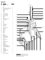
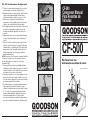
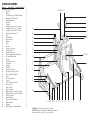
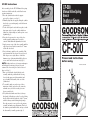
CF-500
CF-500 Instructions
After assembly, place the CF-500 Manual valve spring
bench on a solid flat work table, and follow the next
operation instructions:
1. Place the cylinder head on the side supports
protected by a plastic cover (fig. 1)
2. Manually adjust the side supports, tilting the cylinder
head to the correct working angle, and lock them in
position (fig. 1)
3. Use the dowel pins located at the brace plates, in the
front square tube, to keep the cylinder head from
sliding out of the working area, and keep it in correct
alignment (fig. 1).
4. Now place the pressure foot on top of the valveretainer assembly, making sure it’s perfectly
centered. Make additional adjustments, if needed.
5. Apply pressure on top of the valve assembly until the
support post located at the bottom of the “C” frame
touches the valve head.
6. Now is the time to push the valve assembly all the
way down until the valve keeper locks are released.
If the keepers are too tight, the use of the slider
hammer on top of the main shaft will help. Just one
or two strokes will release them easily. (fig. 2)
NOTE: At this point, the use of tweezers and magnets
will facilitate the retrieving of keeper locks and
retainers. Check our catalog for a wide selection of
these tools (fig. 3)
7. Once you calculate the depth of the first valve
assembly, mark the position with the lock ring
located at the upper part of the main shaft, and
proceed with the disassembly of the rest of the
cylinder head.
8. To assemble, simply reverse the steps of these
instructions. Always replace the valve stem seals,
and make sure you check our catalog for some
keeper assembly tools.
9. For cylinder heads with canted valves (sideways
tilted angle) follow this procedure: Loose the locking
knob located in the back right side of the “C” frame,
and tilt it sideways until reaching the right angle.
Place the pressure foot on top of the valve-retainer
assembly, and make proper adjustments. Then lock
the frame in position with the knob, and proceed with
the disassembly / assembly operation (fig. 4)
Manual Valve Spring
Bench
Instructions
Fig.1
Fig.2
Fig.3
Fig.4
CF-500
Please read instructions
before using.
Review June 2013
Parts List
ID #
1
2
3
4
5
6
7
8
9
10
11
12
13
14
15
16
17
18
19
20
21
22
23
24
25
26
27
28
29
30
31
32
33
34
35
36
37
38
39
40
41
42
43
44
45
46
Description
# included
Plastic Friction Washer
2
Bearing
1
Nut
2
Shouldered Screw (100x10x1.5mm)
1
Washer (10x25x1.5mm)
1
Hammer
1
Washer
4
Screw
4
Pressure Foot-23mm
1
Pressure Foot-28mm
1
Pressure Foot-35mm
1
C-frame
1
Shaft
1
Tensioning Screw, nylon
1
Tensioning Nut
1
Lever
3
Hub
1
Peg
1
Bearing Bracket
1
Screw, nylon
2
Set Screw
2
Lock Lever for Tilt
1
Shaft for Tilt
1
Bracket
1
Set Screw
3
Holder
2
Washer
4
Screw
4
End Bracket
2
Bracket Spacer Shaft*
1
30mm Square Tube
1
Arm
2
Plastic Protection
2
Support
2
15mm Square Tube
1
Brace Plate
2
Tube Pin
2
Cylindrical Pin
2
15mm Plastic End Plug (sq)
2
30mm Plastic End Plug (sq)
2
Stop Ring
1
Lock Handle
1
Nut with Milled Sides
2
Lock Handle
2
Cover
1
Plastic Plug (5mm dia.)
2
17, 21, & 45 46
4
6
5
16
13
28
41
14 & 15
26
24
22
23
19
9, 10 &11
30*
20
33
31
40
1
44
32
29
3, 7 & 8
39 37
36
*PLEASE NOTE: Bracket Spacer Shaft is shipped
INSIDE the 30mm Square Tube (#31). Remove Plastic
End Plug & shaft will then be visible.
38
12
35
18
43
34
CF-500
Compresor Manual
Para Resortes de
Válvulas
CF- 500 Instrucciones de Operación
1. Posicione la culata (cabeza) a trabajar sobre los soportes
laterals protegidos con una base de plástico (fig 1).
2. Manualmente ajuste los soportes laterals, virando la culata
(cabeza) hacia el ángulo apropiado de alineación de
válvulas verticalmente, y aprietelos en posición (fig 1).
3. Utilize los pines localizados en las placas laterales
soportadas en el tubo cuadrado, para posicional la culata
(cabeza) y que no resbale fuera del area de trabajo.
4. Ahora ponga el pié de presión vertical sobre el retenedor de
la válvula a ser desarmada, y asegurese de que está
perfectamente alineada. Haga ajustes necesarios si es
requerido.
5. Aplique presión sobre el poste vertical principal, hasta que
el soporte toque la parte superior de el ensamblaje de la
válvula.
6. Este es el momento de empezar a aplicar presión sobre el
resóste de la válvula, hasta que los seguros (cuñas) estén
totalmente libres, y se puedan retirar. Si los seguros están
muy apretados, el uso del martillo localizado sobre el eje
principal es apropiado. Uno o dós gólpes soltarán los
seguros fácilmente (fig. 2)
NOTA: En este punto el uso de pinzas o de imanes, facilitarán
el alcance de los seguros y de los retenedores, refierase a
nuestro catálogo para una extenza selección de estas
herramientas.(fig.3)
7. Una vez usted haya calculado la profundidad del primer
ensamblaje de válvula, marquee la posición con el anillo de
retención localizado en el eje central vertical, y proceda con
el desarmado del resto de la culata (cabeza).
8. Para armar, simplemente reverse el procedimiento en estas
instrucciones. Recuerde de siempre cambiar los sellos de
aceite de válvulas, y asegurese de revisar nuestro catálogo
por herramientas para facilitar esta labor.
9. En culatas (cabezas) con valvulas inclinadas lateralmente,
siga el siguiente procedimiento: Desapriete el seguro
localizado en la parte trasera derecha del soporte en forma
de “C”, e incline el soporte principal lateralmente hasta
alcanzar el ángulo apropiado, appliqué presión sobre la
válvula para asegurar alineación, y aga los ajustes
necesarios. Luego asegure nuevamente el seguro lateral, y
proceda con el armado / desarmado de dicha pieza. (fig. 4).
Fig.1
Fig.2
Fig.3
Fig.4
CF-500
Por favor leer las
instrucciones antes de usar.
Revisar Junio 2013
LISTA DE PARTES
Número
Descripción Cantidad incluida 1
Arandela de fricción plástica
2
Cojinete
3
Tuerca
4
Tornillo de apoyo (100x10x1.5mm)
5
Arandela (10x25x1.5mm)
6
Martillo deslizante
7
Arandela
8
Tornillo
9
Adaptador para resortes de 23mm
10
Adaptador para resortes de 28mm
11
Adaptador para resortes de 35mm
12
Armazón en forma de “C”
13
Eje
14
Tornillo tensor
15
Tuerca tensora
16
Palanca
17
Cubo
18
Clavija
19
Soporte del cojinete
20
Tornillo, nylon
21
Tornillo de presión
22
Palanca fijadora para inclinación
23
Eje para la inclinación
24
Soporte
25
Tornillo de presión
26
Sostenedor
27
Arandela
28
Tornillo
29
Soporte del extremo
30
Eje del soporte espaciador*
31
Tubo cuadrado de 30mm
32
Brazo
33
Protección plástica
34
Soporte
35
Tubo cuadrado de 15mm
36
Placa de apoyo
37
Perno del tubo
38
Perno cilíndrico
39
Enchufe plástico exterior de 15mm
40
Enchufe plástico exterior de 30mm
41
Collar de parada
42
Manija fijadora
43
Tuerca con lados tallados
44
Manija fijadora
45
Cubierta
46
Enchufe plástico (5mm diámetro)
2
1
2
1
1
1
4
4
1
1
1
1
1
1
1
3
1
1
1
2
2
1
1
1
3
2
4
4
2
1
1
2
2
2
1
2
2
2
2
2
1
1
2
2
1
2
17, 21, & 45 46
4
6
5
16
13
28
41
14 & 15
26
24
22
23
19
9, 10 &11
30*
20
33
31
40
1
44
32
29
3, 7 & 8
39 37
36
*NOTA: El eje del soporte espaciador se envía
ADENTRO del tubo cuadrado de 30mm (#31). Remueva
el enchufe plástico exterior y el eje será visible.
38
12
35
18
43
34