1
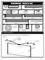
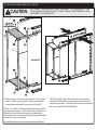
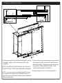
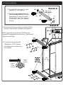
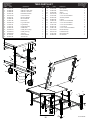
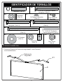
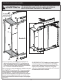
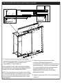
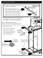
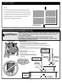
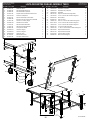
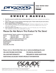
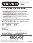
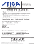
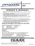
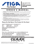
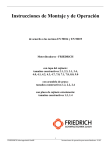
TABLE TENNIS TABLE
MODEL NO.
T8525
OWNER'S MANUAL
1. Read this manual carefully before starting assembly. Read each step completely before beginning
each step.
2. Some smaller parts may be shipped inside larger parts. Check inside all parts and cartons
before assembling or ordering parts.
3. To make assembly easier, use the Hardware Identifier on page 2 to identify and sort all
fasteners. Check all cartons for kits. All hardware may not be located in one kit.
4. Do not tighten hardware until instructed to do so. If hardware is tightened too soon, mounting holes
may not align and parts may not easily fit together. Leave locknuts slightly loose until you are instructed to
tighten them.
5. Tools required for assembly: Phillips Screwdriver, Two 9/16” Wrenches, One 7/16” Wrench.
Note: Adjustable wrenches can be substituted for wrenches.
6. Save this instruction manual and your proof of purchase (receipt) in the event that the
manufacturer has to be contacted for replacement parts.
Please Do Not Return This Product To The Store!
Contact Escalade® Sports customer service department at:
Phone:
1-866-873-3528
Toll – Free !
Fax:
1-866-873-3533
Toll – Free !
E-mail:
[email protected]
Mailing Address (correspondence only):
Escalade Sports
PO Box 889
Evansville, IN 47706
Please visit our World Wide Web site at: www.escaladesports.com
ON-LINE TROUBLE SHOOTING
TECHNICAL ASSISTANCE
ON-LINE PARTS REQUESTS
FREQUENTLY ASKED QUESTIONS
ADDITIONAL ESCALADE® SPORTS PRODUCT INFORMATION
2L-4140-04
Escalade® Sports products may be manufactured and/or licensed under the following patents.
6120397, 5816957, 5769744, 5119741, 4911085, 4717157, D460140, D420563, 8414431
Additional patents may be pending. One or more of the listed patents and/or pending patents may cover specific product.
2013 Escalade Sports
25
19
5/16-18 x 3 Hex Head Bolt
(Qty. 4)
Spacer Bushing (Qty. 4)
20
Spacer
(Qty. 8)
17
28
3/8 Push Nut
(Qty. 4)
27
1/4-20 Locknut
(Qty. 20)
29
1/4-20 X 3 Hex Head Bolt
(Qty. 4)
1/4-20 X 3 1/4 Hex Head Bolt
(Qty. 4)
26
22
1/4-20 X 4 Hex Head Bolt
(Qty. 4)
1/4-20 X 2 Hex Head Bolt
(Qty. 8)
23
33
18
3/8” Washer
(Qty. 4)
Nylon Spacer
(Qty. 8)
M12 Hex Nut
(Qty. 4)
ATTACHING RUBBER PAD
1. Attach Lock Lever Cap #21 to Lock Levers on the Name Panel # 8 as
shown.
Lock
Lever
21
8
2
ATTACHING LEGS TO TABLE TOPS
CAUTION
AT LEAST TWO ADULTS ARE NEEDED TO
COMPLETE THE FOLLOWING STEPS!
il B
Deta
29
28
Rail not
shown for
clarity.
hole
iddle m the
M
r
o le.
e
Upp
ay fr
Use thest aw f the tab
fur ttom o
bo
1
29
ole
dle h m of
d
i
M
er
tto
Low
e bo
Use est to th ble.
a
clos
the t
30
il C
Deta
33
9
31
2. Leave top halves #1 in shipping carton as shown
above or lay them on a carpeted floor (to protect
them from damage and scratches ).
5. Attach upright assembly #11 to remaining brackets
#6 on the bottom of the first top half #1. (See above).
Use bolts #26, spacers #20, and locknuts #28.
(See Detail A and C). Tighten locknuts snug but DO
NOT OVERTIGHTEN them. JOINT MUST MOVE!
3. Attach leg assembly #10 to brackets #6 located on
the bottom of the first top half #1. (See above).
Use bolts #29, spacers #20 and locknuts #28.
(See Detail A and Detail B).
6. If not already installed, slide Right # 30 and Left
#31 Rail caps onto the end of the rails as shown.
NOTE: Be sure brace on leg assembly #10 is against
table (See above). Tighten these locknuts snug but
DO NOT OVERTIGHTEN THEM.
JOINT MUST MOVE!
7. With a helper , set the first top half #1 on its side
against a wall. ( Be sure to put a piece of cardboard,
cloth, or carpeting on the floor first to protect the
top's edges). Turn the second top half #1 over and
repeat steps 3-6 to assemble it.
4. Screw Nuts #33 onto leg levelers # 9 and Put
Levelers #9 on bottom end of leg assembly #10.
(See Detail A)
3
ATTACHING NAME PANELS TO LEGS
CAUTION
AT LEAST TWO ADULTS ARE NEEDED TO COMPLETE THE
FOLLOWING STEPS! DO NOT LEAVE TABLE UNATTENDED UNTIL
ASSEMBLY IS COMPLETE!
Detail D
HELPFUL HINT: Start at the bottom and insert two
bolts #26 UPWARD through upright assemblies #11
and name panel #8. Then attach the upper name panel
#8. Insert bolts #26 DOWNWARD.
8. With a helper , hold top halves about 14 ½ inches
apart. Attach only top half of name panels #8 to
upright assemblies #11 as shown in Detail D.
NOTE: Use ONLY TWO bolts #26 and locknuts #28
on each name panel. (Two other bolts #27 and nuts
#28 will be used in the next section to attach the
other half of the name panels and linkages #24 at the
same time. See next page).
Do not tighten these locknuts completely tight yet .
4
ATTACHING LINKAGE TO LEGS
22
10
27
18
24
18
24
28
11
28
Detail F
Detail E
11
24
18
28
10
22
10. Attach linkages #24 to upright assembly #11 using 11. Attach other end of linkages #24 to leg assembly
bolts #27, spacers #18, and locknuts #28. (See
#10 using bolts #22, spacers #18, and locknuts
Detail E).
#28. (See Detail F). Tighten these locknuts snug,
but DO NOT OVERTIGHTEN THEM. THIS
NOTE: TIGHTEN LOCKNUTS SNUG, BUT DO NOT
JOINT MUST BE ABLE TO MOVE!
OVERTIGHTEN. JOINTS MUST BE ABLE TO MOVE!
NOTE: If you have trouble inserting bolts #27 through
name panels #8, slightly loosen bolts #26 (that you
used in the previous section to attach name panels #8).
(See previous page).
5
12.Repeat steps 10 and 11 on other top half #1.
ATTACHING CASTERS
Detail G
13.Put caps #15 into ends of caster
beams #12 (see Detail G).
14 .Attach one non-locking caster #13
and one locking caster #14 to each
caster beam #12 with push nuts #17.
(See Detail G). Note: Use a hammer
to tap push nuts onto casters
securely.
15. Attach caster beams to upright assemblies #11 with
bolts #25, washers #23, and spacer bushings #19.
NOTE: Spacers bushings #19 slide INSIDE caster
beams #12 to keep beams from crushing. (See Detail H).
Tighten bolts #25 tight.
16. Lock both locking casters #14.
(See Below). NOTE: Casters
should always be locked unless
moving table.
To Unlock
Turn
Clockwise
To Lock
Turn
CounterClockwise
6
Detail H
SETTING TABLE UPRIGHT
CAUTION
At least two adults are needed to complete the following
steps. Be sure top halves are locked in safety latches! Be sure
that both locking casters are locked!
You must use a 8" stack of magazines (or similar block) to
protect the casters when lifting table upright!
8”
17.Before lifting table, be sure both top halves are locked in
safety latches! Be sure casters are locked! Put a 8 inch stack
of magazines, wood, etc. under caster beam nearest the
floor to protect casters. (See Detail K).
18.With the help of one other adult, brace lower caster beam with
your foot and lift table upright. (See Detail L).
19.Once upright, release safety latch and lower table top halves.
See Detail M and OPERATING INSTRUCTIONS on next page.
6. MAKING FINAL ADJUSTMENTS
If your gap between table halves is greater than 1/2" or uneven adjust it as follows.
1/2” or less
20.Loosen the six bolts shown
below and adjust table so
that the space between the
two table top halves
measure a 1/2 inch or less.
21.Retighten these bolts.
22.Check over entire assembly
to be sure all nuts and bolts
are secure. Remember, do
not overtighten bolts at
joints that move.
7
FINISHING THE ASSEMBLY
NOTE:
If sides of table are not even with one
another, loosen the bottom four bolts that
were loosened in the previous page and push
both sides inward as shown until they are even.
Retighten bolts when sides are even.
OPERATING INSTRUCTIONS
CAUTION
!! ALWAYS LOCK TABLE TOP HALVES IN SAFETY LATCHES WHEN STORING,
MOVING, OR USING TABLE IN ITS PLAYBACK POSITION!
!!! ALWAYS LOCK CASTERS, EXCEPT WHEN MOVING TABLE!
!!! DO NOT SIT, STAND, WALK OR JUMP ON THIS TABLE!
!!! DO NOT ALLOW CHILDREN TO PLAY ON OR NEAR TABLE! SERIOUS OR FATAL
INJURY COULD RESULT.
To open table:
1. Lock both locking casters.
2. With the aid of another adult, hold table half
with one hand and release safety latches
(both at the same time).
3. Open table half slightly, until free of safety
latches.
4. With both hands on table half, lower table top
half.
5. Repeat on other half.
To close table:
1. Be sure both locking casters are locked.
2. Lift table top half until edge of table half locks
securely in safety latches.
DO NOT ALLOW
CHILDREN TO PLAY
ON OR AROUND
TABLE! SERIOUS OR
FATAL INJURY
COULD RESULT!
8
ONE YEAR LIMITED WARRANTY
This consumer warranty extends to the original consumer purchase of any ESCALADE® SPORTS Product
(hereinafter referred as the "Product").
WARRANTY DURATION: This Product is warranted to the original consumer purchase of a period of one (1) year from the original
purchase.
WARRANTY COVERAGE: ESCALADE SPORTS warrants to the original Consumer Purchaser that any Product of its manufacture is free from
defects in material and workmanship when used for the intended purpose under normal use and conditions. THIS WARRANTY IS VOID IF THE
PRODUCT HAS BEEN DAMAGED BY ACCIDENT, UNREASONABLE USE, NEGLIGENCE, IMPROPER SERVICE, FAILURE TO FOLLOW INSTRUCTIONS PROVIDED WITH THE PRODUCT OR OTHER CAUSES NOT ARISING OUT OF DEFECTS IN MATERIAL AND WORKMANSHIP.
WARRANTY PERFORMANCE: During the above one (1) year warranty period, ESCALADE SPORTS shall repair or replace with a
comparable model, and Product, or component thereof, which may prove defective under normal use and proper care, and which our
examination shall disclose to our satisfaction to be thus defective, please contact our Warranty Dept.
1-866-873-3528 / Warranty Dept.
Or Write us at:
Escalade® Sports, Inc. - P.O. Box 889, Evansville, IN 47706 - Attn: Warranty Dept.
Or E-mail us at:
[email protected]
Other than shipping requirements no charge will be made for such repair or replacement of in-warranty Products. ESCALADE® SPORTS
strongly recommends that the Product is insured for value prior to mailing.
WARRANTY DISCLAIMERS: ANY IMPLIED WARRANTIES ARISING OUT OF THIS SALE, INCLUDING BUT NOT LIMITED TO THE
IMPLIED WARRANTIES OF MERCHANTABILITY AND FITNESS FOR A PARTICULAR PURPOSE, ARE LIMITED IN DURATION TO THE
ABOVE ONE (1) YEAR WARRANTY PERIOD. ESCALADE® SPORTS SHALL NOT BE LIABLE FOR LOSS OF USE OF THE PRODUCT OR
OTHER CONSEQUENTIAL OR INCIDENTAL COSTS, EXPENSES OR DAMAGES INCURRED BY THE CONSUMER OF ANY OTHER USE.
Some states do not allow the exclusion or limitation of implied warranties or consequential or incidental damages, so the above
limitations or exclusions may not apply to you.
LEGAL REMEDIES: This warranty gives you specific legal rights and you may also have other rights which may vary from state to state.
CARE AND MAINTENANCE
You have purchased a quality product that will give you years of enjoyment. By following these simple maintenance steps, you will add to the life of your new table.
THE TABLE TOP
The top (playing surface) of your table is made of particle board or MDF. Like all products made of wood, it can be affected by atmospheric changes in both temperature and
humidity. This may cause a slight sag or distortion as the top expands or contracts. This is normal and should not cause concern as it does not detract from the play or utility value
of the table. After assembly of the table, you can minimize the effects of temperature and humidity changes by storing the table in the folded up position in a dry area when table
is not in use.
STORAGE OF YOUR TABLE
This table must be stored indoors to prevent damage to the playing surface. Dampness and extreme temperature changes can cause the wood to warp, swell, crack or blister.
When your table is not in use, it should be folded up in a dry area. Due to the nature of particle board, table top may bow. Damp and humid conditions will amplify this. This is
normal and will not affect playability of table.
CLEANING YOUR TABLE
To clean your table use a soft, damp (NOT WET) cloth only. To prevent damage to your table's playing surface, DO NOT USE ANY CHEMICALS, ABRASIVE OR CLEANING
PRODUCTS on your table's playing surface.
MAINTENANCE OF YOUR TABLE
Be sure to oil all moving parts of your table including the pivot points. This will insure the safety and ease of use of your table.
This table must be kept indoors to prevent damage to the playing surface. Dampness and extreme temperature changes which occur on patios or similar areas can cause wood
to warp, swell, crack or blister.
UNLEVEL FLOORS
If table does not seem level, it is probably due to uneven or unlevel floors. Set the table in its PLAYING POSITION and move table several inches in different directions to find the
best location for the table then use leg levelers provided to level table. If the floor is extremely unlevel, table may not play or operate properly.
9
Use PART # column
when calling for
replacement parts.
ITEM #
1
2
3
4
5
6
7
8
9
10
11
12
13
14
15
16
17
QTY. column refers to
the total number of
pieces in product.
T8525 PARTS LIST
PART#
DESCRIPTION
4A-6324-01
2S-4668-02
2S-4668-03
2S-5136-02
3M-4167-00
2S-6139-01
1B-4082-99
4A-6161-08
2Q-6467-00
1A-4128-01
1A-4130-01
8S-6503-02
2Q-4025-01
2Q-4026-01
3M-6248-00
2L-4140-04
2B-4043-02
26
ITEM #
QTY
Table Top Half
Side Rail - Right Hand
Side Rail - Left Hand
Ball Holder End Rail
Corner Protector
Mounting Bracket
#8 x 9/16 Screw
Name Panel
Leg Leveler M12
Leg Assembly
Upright Assembly
Caster Beam
Caster (Non-locking)
Caster (Locking)
Tube Plug
Owner's Manual
3/8 Push Nut
2
2
2
2
4
8
134
2
2
2
2
2
2
2
4
1
4
PART#
18
19
20
21
22
23
24
25
26
27
28
29
30
31
32
33
DESCRIPTION
7B-4059-02
7B-6240-03
7B-4046-02
3M-4143-00
1B-4159-02
2B-5045-00
8S-6504-03
1B-6047-02
WB-1110-02
1B-5012-02
2B-4047-02
1B-6477-02
3M-4150-00
3M-4151-00
5A-4276-00
2B-6284-00
QTY.
Nylon Spacer
Spacer Bushing
Spacer
Lock Lever Cap
¼ -20 x 4 Hex Head Bolt
3/8 Heavy Washer
Linkage
5/16-18 x 3 Hex Head Bolt
¼ -20 x 2 Hex Head Bolt
¼ -20 x 3 Hex Head Bolt
¼ -20 Locknut
¼ -20 x 3-1/4 Hex Head Bolt
RH Rail End Cap
LH Rail End Cap
Net and Post Set
Hex Nut M12
8
4
8
4
4
4
4
4
8
4
20
4
2
2
1
4
20
28
8
4
28
7
5
18
28
27
7
17
6
13
12
15
1
2
19
7
3
23
14
25
30
31
29
21
20
28
8
11
24
22
28
18
10
24
10
33
(Nut)
9
2L-4140-04
MESA DE TENIS
NÚMERO DE MODELÓ
T8525
MANUAL DEL USUARIO
1. Lea este manual cuidadosamente antes de empezar a ensamblar. Lea completamente cada uno de los
pasos antes de empezar cada paso.
2. Algunas partes pequeñas pueden ser empacadas dentro de las partes grandes. Verifique en el interior
de todas las partes y cartones antes de ensamblar o solicitar partes.
3. Para que el ensamblado le sea más fácil, utilice la lista de partes de la página 2 para la identificación y
clasificación de las partes y sus componentes. Busque los juegos de tornillos en todos los cartones.
Todos los tornillos y sus componentes no se encuentren en un sólo juego.
4. No ajuste las partes hasta que las instrucciones se lo indiquen. Si las partes se ajustan antes de lo indicado,
es posible que los orificios no queden alineados, resultando que las partes queden fuera de su lugar y fácilmente no
coincidan. Deje las tuercas de seguridad levemente flojas hasta que las instrucciones le indiquen ajustarlas.
5. Herramientas necesarias: Desarmador Phillips, dos llaves de 9/16” y una llave de 7/16” (Puede utilizar una llave
ajustable en vez de llaves).
6. Guarde estas instrucciones y recibo de pago en el evento que el fabricador deba de ser contactado
para partes de remplazo.
Por favor NO devuelva este producto a la tienda!
Contacte el departamento de servicio al cliente de Escalade® Sports:
Teléfono:
1-866-873-3528
¡Sin costo alguno!
Fax:
1-866-873-3533
¡Sin costo alguno!
Correo Electronico:
[email protected]
Apartado postal (sólo para correspondencia):
Escalade Sports
PO Box 889
Evansville, IN 47706
Visite nuestra página Web internacional: www.escaladesports.com
SOLUCION DE PROBLEMAS POR INTERNET
ASISTENCIA TÉCNICA
PEDIDO DE PARTES POR INTERNET
PREGUNTAS FRECUENTES
MÁS INFORMACIÓN SOBRE PRODUCTOS DE ESCALADE® SPORTS
2L-4140-04
Los productos Escalade® Sports se pueden fabricar y/o producir bajo las siguientes patentes.
6120397, 5816957, 5769744, 5119741, 4911085, 4717157, D460140, D420563, 8414431
Puede haber patentes en trámite. Una o más patentes mencionadas y/o en trámite pueden cubrir productos específicos.
2013 Escalade Sports
IDENTIFICADOR DE TORNILLOS
25
19
5/16-18 x 3 Tornillo de Cabeza
Hexagonal (Cant. 4)
Separador (Cant. 4)
20
17
Separador
(Cant. 8)
28
3/8 Tapón de Remache
(Cant. 4)
27
1/4-20 Tuerca de
Seguridad
29
1/4-20 X 3 Tornillo de Cabeza
Hexagonal (Cant. 4)
1/4-20 X 3 1/4 Tornillo de Cabeza Hexagonal
(Cant. 4)
26
22
1/4-20 X 4 Tornillo de Cabeza Hexagonal
(Cant. 4)
1/4-20 X 2 Tornillo de
Cabeza Hexagonal (Cant.8)
23
33
18
3/8” Rondana
(Cant. 4)
Separador
(Cant. 8)
M12 Tuerca
(Qty. 4)
ATTACHING RUBBER PAD
1. Coloque el Tapón de la Palanca de seguridad #21 a las Placas #8
como esta Mostrado.
Palanca de
Seguridad
21
8
2
COLOCACION DE LAS PATAS A LOS TABLEROS
ADVERTENCIA
SE REQUIEREN POR LO MENOS DOS ADULTOS
PARA COMPLETAR LOS SIGUIENTES PASOS:
lle B
Deta
Las Mitades de los Tableros
(#1) (déjelas en la caja de
cartón de envío cara a cara)
29
28
emo
l Extr
e
Riel d
o
ifici
l or perior B
e
e
u
Us tral/s etalle
cen a el D
Ve
1
de
Barra rte
p
o
S o
Riel no
mostrado
io s
rific
á
el o rior m a el
e
s
U l/infe a, ve
es
tra
cen a la m lle C.
a
a
Det
cerc
29
Detalle A
30
eC
ll
Deta
33
9
31
2.Deje las mitades de los tableros # 1 en la caja de
cartón de envío como se muestra arriba o póngalo
sobre el piso alfombrado (para protegerlos contra
daños y ralladuras).
5. Coloque Patas pequeñas ensambladas #11 a los
soportes #6 restantes en la parte inferior de la
primera mitad del tablero # 1. Utilizando los
tornillos #26, los separadores #20, y las tuercas
#28. (Vea Detalle A y C). Apriete las tuercas de
seguridad ajustándolas, pero NO LAS
SOBREAPRIETE YA QUE LAS UNIONES DEBEN
MOVERSE
6. coloque las Tapas del Riel #30 (Derecha) y #31
(Izquierda) en los extremos de los rieles como se
muestra.
7. Con un ayudante, ponga la primera mitad del
tablero # 1. de lado contra una pared. (Primero
asegúrese de poner un pedazo de cartón, tela o
alfombra en el piso para proteger los bordes del
tablero). Voltee la segunda mitad del tablero #1 y
Repita los pasos del 3 al 6 para ensamblarla.
3. Coloque las Patas Grandes Ensambladas #10 a
los Soportes #6 localizados en la parte inferior de
la primera mitad del tablero #1, utilizando los
tornillos #29, los separadores #20 y las tuercas de
seguridad #28.(Vea el Detalle A y B).
NOTA: Asegúrese que la Barra de Soporte de las
patas grandes ensambladas #10 esté recargada
contra de la mesa Vea el dibujo arriba. NO
SOBREAPRIETE LAS TUERCAS YA QUE LAS
UNIONES DEBEN MOVERSE
4. Atornille las Tuercas #33 a los Niveladores de las
Patas # 9 y Enrosque los Niveladores #9 en la
parte inferior de la Patas #10 Vea el Detalle A.
3
COLOQUE LAS PLACAS A LA MESA
ADVERTENCIA
SE REQUIEREN POR LO MENOS DOS ADULTOS PARA COMPLETAR
LOS SIGUIENTES PASOS! NO DEJE LA MESA DESATENDIDA
HASTA QUE SE HAYA FINALIZADO EL ENSAMBLADO!
No coloque los
tornillos aquí
todavía! (Vea la
sección siguiente)
S
ADA
LG
2 PU
/
14 1
Detalle D
8. Con un ayudante, mantenga las mitades de los
tableros a una distancia de 14 ½ pulgadas entre
ellas. Únicamente coloque la mitad de las Placas
con nombre #8 a las Patas pequeñas ensambladas
#11. Como se muestra en el Detalle D.
SUGERENCIA ÚTIL: Empiece por la parte inferior
e inserte los dos tornillos # 26 HACIA ARRIBA a
través de las Patas pequeñas ensambladas #11 y
la placa con nombre #8. Despues, en la parte
NOTA: Utilice en cada placa #8 DOS TORNILLOS #26 superior coloque la placa con nombre # 8 e Inserte
los tornillos # 26 HACIA ABAJO.
UNICAMENTE y las tuercas #28. Como se muestra
arriba. Todavía no apriete las tuercas de seguridad
completamente. (Los otros dos tornillos #27 y las
tuercas #28 se utilizarán en la siguiente sección para
colocar la otra mitad de las placas con nombre y los
tubos conectores #24 al mismo tiempo. Vea la página
siguiente).
4
COLOCACION DE LOS TUBOS CONECTORES A LAS PATAS
22
10
27
18
24
18
24
28
11
28
Detalle F
Detalle E
11
24
18
28
10
22
10. Coloque los tubos conectores # 24 a las Patas
pequeñas ensambladas # 11 utilizando los tornillos 11.Coloque en el otro extremo de los tubos
conectores # 24 a las Patas grandes
# 27, los espaciadores # 18 y las tuercas de
ensambladas # 10 utilizando los tornillos # 22, los
seguridad # 28. Vea el Detalle E.
espaciadores # 18 y las tuercas de seguridad #
NOTA: APRIETE LAS TUERCAS DE SEGURIDAD
28. (Vea el Detalle F). Apriete estas tuercas de
AJUSTANDOLAS, PERO NO LAS SOBREAPRIETE
seguridad
ajustándolas, pero NO LAS
YA QUE LAS UNIONES DEBEN MOVERSE!
SOBREAPRIETE YA QUE LAS UNIONES
DEBEN MOVERSE!
NOTA: Si tiene problemas para insertar los tornillos #
27 a través de la placa con nombre # 8, entonces afloje
un poco los tornillos # 26 (que utilizó para colocar la
12. Repita los pasos del 10 al 11 en la otra mitad del
placa con nombre # 8 en la sección anterior). Vea la
tablero # 1.
página anterior.
5
COLOCACIÓN DE LAS LLANTAS
13. Ponga los Tapones #15 en los extremos de los
carriles #12. Vea el Detalle G.
14. Inserte una Llanta sin Seguro #13 y una
Llanta con Seguro #14 a cada Carril #12 con
los Tapones de Remache #17. (Vea el Detalle
G). Nota: Utilice un martillo para golpear
ligeramente sobre los tapones de Remache
para insertarlas firmemente en las llantas.
15. Coloque el carril para las llantas a las Patas pequeñas
ensambladas #11 utilizando los tornillos #25, las
rondanas #23, y los separadores (casquillos) # 19.
NOTA: Los separadores (casquillos) #19
insertarse DENTRO del carril #12 para evitar que se
deformen al apretarse. (Vea el Detalle H). Apriete los
tornillos # 25 bien ajustados.
16. Ponga el seguro a las dos llantas
con seguro # 14. (Vea abajo).
NOTA: Las llantas siempre deben
tener el seguro puesto a menos
que vaya a mover la mesa.
Para quitar el
seguro, de vuelta
en sentido de las
agujas del reloj.
Ponga diagonalmente
las llantas (con seguro)
cruzadas una de la otra
Para poner el
seguro, de vuelta en
sentido contrario de
las agujas del reloj.
6
Detalle G
Ponga las llantas en
los orificios mas
cerca al extremo.
Detalle H
COLOCAR LA MESA A LA POSICIÓN VERTICAL
ADVERTENCIA
Se requieren por lo menos dos adulos para completar los siguientes pasos.
Asegúrese que las dos mitades de la mesa tengan puesto el pasador de
seguridad! También Asegúrese que ambas llantas con seguro tengan
puesto el seguro! Debe utilizar varias revistas hasta que la altura mida 8
pulgadas (o un bloque similar) para proteger las llantas cuando levante la
mesa en la posición vertical!
Detalle K
Detalle M
8”
Detalle L
17.Antes de que levante la mesa, asegúrese que las dos mitades de
la mesa tengan puesto el pasador de seguridad! También
Asegúrese que ambas llantas con seguro tengan puesto el
seguro! Coloque varias revistas (o madera) hasta que la altura
mida 8 pulgadas, debajo del carril con llantas lo más cercano al
piso para proteger las llantas. (Vea el Detalle K).
18.With la ayuda de otro adulto, apoye con su pie la parte inferior del
riel con llantas y levante la mesa verticalmente. (Vea el Detalle L).
19.Una vez que esté en la posición vertical, quite el pasador de
seguridad y baje las dos mitades de la mesa. (Vea el Detalle M y
las Instrucciones de Operación en la siguiente página).
AJUSTES FINALES
Si la distancia entre las mitades de mesa es mayor que 1/2 pulgada o menos, ajústela de la siguiente manera.
20.Afloje los seis tornillos que se
muestran a continuación y ajuste
la mesa de manera que el espacio
entre las dos mitades de la mesa
mida 1/2 pulgada o menos.
21.Vuelva a apretar estos tornillos.
1/2” o menos
Aflojar
Aflojar
Aflojar
Aflojar
22.Verifique completamente todo lo que
ensambló, para asegurarse de que
todas las tuercas y tornillos estén
ajustados apropiadamente. Recuerde,
no sobre-apriete los tornillos en las
uniones que se mueven.
Afloje estos 4 tornillos
para alinear las mitades
de la mesa. Después
vuelva a apretarlos.
7
AJUSTES FINALES
NOTA:
Si los lados de los tableros no están parejas, afloje
los tornillos de la parte de abajo que fueron aflojados
en la pagina anterior y empuje los dos tableros hasta
que estén parejos. Vuelva a apretar los tornillos
cuando estén los tableros parejos.
Vista Superior
INSTRUCCIONES DEL FUNCIONAMIENTO Y EL USO
ADVERTENCIA
!!SIEMPRE PONGA EL PASADOR DE SEGURIDAD PARA ASEGURAR LAS MITADES DE LA MESA
CUANDO NECESITE GUARDARLA, MOVERLA O USAR LA MESA EN SU POSICIÓN DE JUEGO!
!! LAS LLANTAS SIEMPRE TIENEN QUE TENER EL SEGURO PUESTO, EXCEPTO CUANDO
NECESITE MOVER LA MESA!
!! NO SENTARSE, SUBIRSE, PARARSE, CAMINAR O BRINCAR SOBRE LA MESA!
!! NO PERMITA QUE LOS NIÑOS JUEGUEN EN O CERCA DE LA MESA! YA QUE PODRIAN
RESULTAR LESIONES GRAVES O FATALES.
Abrir la Mesa con
dos personas
Para abrir la mesa:
1. Ponga el seguro a las dos llantas con seguro.
2. Con la ayuda de otro adulto, detenga la mitad de la mesa con una mano y
desenganche los pasadores de seguridad (ambos al mismo tiempo).
3. Abra ligeramente la mitad de la mesa, hasta que los pasadores de seguridad
queden libres.
4. Con ambas manos sobre la mitad de la mesa, baje la mitad de la mesa.
5. Repita los mismos pasos en la otra mitad de la mesa.
POSICIÓN DE
ALMACENAMIENTO
Para cerrar la mesa:
(MESA CERRADA)
1. Asegúrese de poner el seguro a las dos
llantas con seguro.
2. Levante la mitad de la mesa hasta que las
orillas estén aseguradas con los pasadores
Palanca de
de seguridad.
seguridad de
arriba asegurada
POSICIÓN DE JUEGO
Palanca de
seguridad de
arriba asegurada
(UNA PERSONA)
NO PERMITA QUE LOS
NIÑOS JUEGUEN EN O
CERCA DE LA MESA! YA
QUE PODRIAN RESULTAR
LESIONES GRAVES O
FATALES.
Llanta
asegurada
Palanca de
seguridad de
arriba asegurada
Llanta
asegurada
POSICIÓN DE
JUEGO
(MESA ABIERTA)
Llanta
asegurada
8
GARANTÍA LIMITADA POR UN AÑO
Esta garantía es aplicable para consumidores de la compra original de cualquier producto ESCALADE® SPORTS (en adelante denominado el
"Producto").
DURACIÓN DE LA GARANTÍA: Se garantiza este Producto al comprador original por un período de un (1) año a partir de la fecha de compra.
COBERTURA DE LA GARANTÍA: ESCALADE SPORTS le garantiza al comprador original que cualquier producto de su fabricación está libre de
defectos en los materiales y fabricación cuando se lo utiliza para el propósito establecido, bajo condiciones normales de uso. ESTA GARANTÍA
NO TIENE VALIDEZ SI EL PRODUCTO SE HA DETERIORADO POR ACCIDENTE, USO INDEBIDO, NEGLIGENCIA, MANTENIMIENTO
INCORRECTO, NO SEGUIR LAS INSTRUCCIONES QUE VIENEN CON EL PRODUCTO U OTRAS CAUSAS NO RELACIONADAS CON
DEFECTOS EN LOS MATERIALES O FABRICACIÓN.
APLICACIÓN DE LA GARANTÍA: Durante el período de garantía de un (1) año, ESCALADE SPORTS reparará o reemplazará con otro similar,
todo modelo o Producto o componente que resulte defectuoso bajo condiciones normales de uso y cuidado, cuando nuestra inspección
demuestre que a nuestra satisfacción el mismo realmente es defectuoso; sírvase contactar a nuestro Departamento de Garantía.
1-800-467-1245 / Departamento de Garantía (Warranty Dept.)
O escríbanos a:
Escalade® Sports, Inc. - P.O. Box 889, Evansville, IN 47706 - Attn: Warranty Dept.
O por correo electrónico a:
[email protected]
Fuera de los gastos de envío, no se impondrá cargo alguno por la reparación o reemplazo de los productos en garantía. ESCALADE® SPORTS
recomienda asegurar los Productos por su valor antes del envío.
LIMITACIÓN DE LA GARANTÍA: TODA GARANTÍA ORIGINADA EN ESTA VENTA, INCLUYENDO EN FORMA NO TAXATIVA, LAS
GARANTÍAS IMPLÍCITAS DE COMERCIALIZACIÓN Y APTITUD PARA UN FIN ESPECÍFICO, TENDRÁ VIGENCIA POR UN PLAZO DE UN (1)
AÑO. ESCALADE® SPORTS NO SERÁ RESPONSABLE POR LA IMPOSIBILIDAD DE UTILIZAR EL PRODUCTO U OTROS COSTOS
INCIDENTALES O RELACIONADOS, PERJUICIOS O PERDIDAS GENERADAS POR EL CONSUMIDOR ANTE CUALQUIER OTRO USO.
Algunos estados no permiten la exclusión o limitación de las garantías implícitas o daños incidentales o conexos, de modo que las limitaciones
que anteceden pueden no ser aplicabes en su caso.
RECURSOS LEGALES: Esta garantía le otorga algunos derechos específicos además de otros derechos que varían según el estado.
CUIDADO Y MANTENIMIENTO
Usted ha comprado un producto de calidad que podrá disfrutar muchos años. Si sigue estos simples pasos de mantenimiento, alargará la vida de la mesa.
TABLERO
El tablero (superficie de juego) está construido de aglomerado. Al igual que todos los productos de madera, se puede ver afectado por cambios de temperatura y humedad
causando una leve deformación por expansión o contracción. Esta situación es normal y no resta valor a la mesa ni afecta el juego. Después de armada, guardar plegada en
lugar seco cuando no está en uso para minimizar los efectos de cambios de temperatura y humedad.
GUARDADO DE LA MESA
Se debe guardar la mesa en el interior para prevenir daños en la superficie de juego. La humedad y los cambios buscos de temperatura pueden provocar alabeo, hinchazón,
fisuras o ampollado de la madera. Cuando la mesa no se encuentra en uso, guardar plegada en lugar seco. debido a la naturaleza del aglomerado, se puede alabear la
superficie. La humedad puede aumentar este efecto que es normal y no afecta el uso de la mesa.
LIMPIEZA
Para limpiar la mesa, utilizar un trapo suave y húmedo solamente (NO MOJADO). Para evitar daños en la superficie de juego, NO UTILIZAR AGENTES QUÍMICOS,
ABRASIVOS NI PRODUCTOS DE LIMPIEZA sobre el tablero.
MANTENIMIENTO
Lubricar todas las partes movibles, incluyendo los puntos de giro. Esto garantizará la seguridad y facilidad de uso.
Guardar en lugar cerrado para impedir daños en la superficie de juego. La humedad y los cambios bruscos de temperatura que se producen en patios o áreas similares
pueden provocar el alabeo, hinchazón, fisuras o ampollado de la madera.
PISOS DESNIVELADOS
Si la mesa no parece estar nivelada, probablemente se deba a pisos desparejos o desnivelados. Colocar la mesa en POSICIÓN DE JUEGO y moverla algunas pulgadas en
distintas direcciones hasta encontrar una mejor ubicación. Si el piso está extremadamente desnivelado, no se puede utilizar la mesa adecuadamente. Si el tablero está más
alto en el medio, suplementar con una cuña las patas exteriores.
9
Utilice el no. de la PARTE
cuando llame para solicitar
piezas de repuesto.
Descripción
No. de Ref. No. de Parte
1
2
3
4
5
6
7
8
9
10
11
12
13
14
15
16
17
4A-6324-01
2S-4668-02
2S-4668-03
2S-5136-02
3M-4167-00
2S-6139-01
1B-4082-99
4A-6161-08
2Q-6467-00
1A-4128-01
1A-4130-01
8S-6503-02
2Q-4025-01
2Q-4026-01
3M-6248-00
2L-4140-04
2B-4043-02
“CANT.” se refiere al
número total de las
piezas del producto.
LISTA DE PARTES PARA EL MODELO T8525
26
No. de Ref.
Cant.
Mitad del Tablero
Riel lateral Mano Derecha
Riel lateral Mano Izquierda
Recipiente de Pelotas/ Riel del Extremo
Protector de Esquinas
Soporte de Montaje en Escuadra
#8 X 9/16" Tornillo para Lamina de Metal
Placas con nombre (Stiga)
Nivelador de las Patas
Pata Grande Ensamblada
Pata Pequeña Ensamblada
Carril para las llantas
Llanta sin Seguro
Llanta con Seguro
Tapón del Tubo
Manual del Usuario
3/8 Tapón de Remache
2
2
2
2
4
8
134
2
2
2
2
2
2
2
4
1
4
18
19
20
21
22
23
24
25
26
27
28
29
30
31
32
33
Descripción
No. de Parte
7B-4059-02
7B-6240-03
7B-4046-02
3M-4143-00
1B-4159-02
2B-5045-00
8S-6504-03
1B-6047-02
WB-1110-02
1B-5012-02
2B-4047-02
1B-6477-02
3M-4150-00
3M-4151-00
5A-4276-00
2B-6284-00
Cant.
8
4
8
4
4
4
4
4
8
4
20
4
2
2
1
4
Separador de plástico
Separador del (Casquillo)
Separador
Tapón de la Palanca de Seguridad
¼ -20 x 4 Tornillo de Cabeza Hexagonal
3/8 Rondana
Tubo Conector
5/16-18 x 3 Tornillo de Cabeza Hexagonal
¼ -20 x 2 Tornillo de Cabeza Hexagonal
¼ -20 x 3 Tornillo de Cabeza Hexagonal
¼ -20 Tuerca de Seguridad
¼ -20 x 3-1/4 Tornillo de Cabeza Hexagonal
Tapón del Riel Derecho
Tapón del Riel Izquierdo
Juego de Red y Postes
M12 Tuerca Hexagonal
20
28
8
4
28
7
5
18
28
27
7
17
6
13
12
15
1
2
19
7
3
23
14
25
30
31
29
21
20
28
8
11
24
22
28
18
10
24
33
(Tuerca)
10
9
2L-4140-04