1
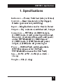
© Copyright 1997. Black Box Corporation. All rights reserved.
1000 Park Drive • Lawrence, PA 15055-1018 • 724-746-5500 • Fax 724-746-0746
FEBRUARY 1997
SW702A
SW702AE-R2
Lead Sensing Relay
LEAD
OUT
DATA
P
O
W
E
R
S
W
I
T
C
H
E
D
R
E
S
E
T
D
I
S
A
B
L
E
AY
G REL
SENSIN
UT
OUTP
CUSTOMER SUPPORT INFORMATION
Order toll-free in the U.S. 24 hours, 7 A.M. Monday to midnight Friday: 877-877-BBOX
FREE technical support, 24 hours a day, 7 days a week: Call 724-746-5500 or fax 724-746-0746
Mail order: Black Box Corporation, 1000 Park Drive, Lawrence, PA 15055-1018
Web site: www.blackbox.com • E-mail: [email protected]
LEAD SENSING RELAY
FEDERAL COMMUNICATIONS COMMISSION
RADIO FREQUENCY INTERFERENCE STATEMENT
This equipment generates, uses, and can radiate radio frequency
energy and if not installed and used properly, that is, in strict
accordance with the manufacturer’s instructions, may cause
interference to radio communication. It has been tested and
found to comply with the limits for a Class A computing device
in accordance with the specifications in Subpart J of Part 15 of
FCC rules, which are designed to provide reasonable protection
against such interference when the equipment is operated in a
commercial environment. Operation of this equipment in a
residential area is likely to cause interference, in which case the
user at his own expense will be required to take whatever
measures may be necessary to correct the interference.
Caution:
Changes or modifications not expressly approved by the
party responsible for compliance could void the user’s
authority to operate the equipment.
This digital apparatus does not exceed the Class A limits for Radio noise
emission from digital apparatus set out in the Radio Interference
Regulation of the Canadian Department of Communications.
Le présent appareil numérique n’émet pas de bruits radioélectriques
dépassant les limites applicables aux appareils numériques de la classe A
prescrites dans le Règlement sur le brouillage radioélectrique édicté par le
ministère des Communications du Canada.
2
CHAPTER
NORMAS OFICIALES MEXICANAS (NOM)
ELECTRICAL SAFETY STATEMENT
INSTRUCCIONES DE SEGURIDAD
1. Todas las instrucciones de seguridad y operación deberán ser leídas
antes de que el aparato eléctrico sea operado.
2. Las instrucciones de seguridad y operación deberán ser guardadas
para referencia futura.
3. Todas las advertencias en el aparato eléctrico y en sus instrucciones
de operación deben ser respetadas.
4. Todas las instrucciones de operación y uso deben ser seguidas.
5. El aparato eléctrico no deberá ser usado cerca del agua—por
ejemplo, cerca de la tina de baño, lavabo, sótano mojado o cerca de
una alberca, etc..
6. El aparato eléctrico debe ser usado únicamente con carritos o
pedestales que sean recomendados por el fabricante.
7. El aparato eléctrico debe ser montado a la pared o al techo sólo
como sea recomendado por el fabricante.
8. Servicio—El usuario no debe intentar dar servicio al equipo
eléctrico más allá a lo descrito en las instrucciones de operación.
Todo otro servicio deberá ser referido a personal de servicio
calificado.
9. El aparato eléctrico debe ser situado de tal manera que su posición
no interfiera su uso. La colocación del aparato eléctrico sobre una
cama, sofá, alfombra o superficie similar puede bloquea la
ventilación, no se debe colocar en libreros o gabinetes que impidan
el flujo de aire por los orificios de ventilación.
10. El equipo eléctrico deber ser situado fuera del alcance de fuentes
3
LEAD SENSING RELAY
11.
12.
13.
14.
15.
16.
17.
18.
4
de calor como radiadores, registros de calor, estufas u otros
aparatos (incluyendo amplificadores) que producen calor.
El aparato eléctrico deberá ser connectado a una fuente de poder
sólo del tipo descrito en el instructivo de operación, o como se
indique en el aparato.
Precaución debe ser tomada de tal manera que la tierra fisica y la
polarización del equipo no sea eliminada.
Los cables de la fuente de poder deben ser guiados de tal manera
que no sean pisados ni pellizcados por objetos colocados sobre o
contra ellos, poniendo particular atención a los contactos y
receptáculos donde salen del aparato.
El equipo eléctrico debe ser limpiado únicamente de acuerdo a las
recomendaciones del fabricante.
En caso de existir, una antena externa deberá ser localizada lejos de
las lineas de energia.
El cable de corriente deberá ser desconectado del cuando el equipo
no sea usado por un largo periodo de tiempo.
Cuidado debe ser tomado de tal manera que objectos liquidos no
sean derramados sobre la cubierta u orificios de ventilación.
Servicio por personal calificado deberá ser provisto cuando:
A: El cable de poder o el contacto ha sido dañado; u
B: Objectos han caído o líquido ha sido derramado dentro del
aparato; o
C: El aparato ha sido expuesto a la lluvia; o
D: El aparato parece no operar normalmente o muestra un
cambio en su desempeño; o
E: El aparato ha sido tirado o su cubierta ha sido dañada.
CHAPTER 1: Specifications
1. Specifications
Indicators — Power, Switched (relay activated)
Controls — Reset (resets relay after trigger),
Disable (prevents relay switching)
Input — Ring Indicator and/or Carrier Detect
Output — Dry contacts or switched AC, 5 amps
Connectors — SW702A: (1) DB25 female,
(1) DB25 male, (1) AC power input (through
line cord), (1) standard three-wire AC power
outlet; SW702AE-R2: (1) DB25 female,
(1) DB25 male, (1) IEC female AC power
output, (1) IEC male AC power input
Power — 120/240 VAC, switch-selectable
(SW702A comes set for 120 VAC;
SW702AE-R2 comes set for 240 VAC)
Size — 2.5"H × 8"W × 6.3"D (6.4 × 20.3 ×
16 cm)
Weight — 3 lb. (1.4 kg)
5
LEAD SENSING RELAY
2. Introduction
The Lead Sensing Relay (or LSR, for short) uses
modem signals to control external equipment: It
receives RS-232 output from a modem and uses
one or more signals to control a relay.
You can choose whether the output is switched
dry contacts or switched AC power, and whether
the output is normally off (circuit open) or on
(circuit closed). There’s also a switch to choose
between 120-volt and 240-volt power.
The output is through a standard three-wire AC
power outlet (for the SW702AE-R2 version, a standard IEC female three-wire AC power outlet). Both
the circuitry and the output are fuse-protected.
Caution!
Always disconnect the LSR from AC power when you install
or disconnect it.
For security, you can set the Disable switch, so that
the LSR can’t be switched accidentally.
If you have a special application, several customized options—timer functions, alarm functions
(serial or parallel), and additional external
controls—can be special-ordered. Call with your
particular requirements.
6
CHAPTER 3: Configuring the LSR
3. Configuring the LSR
In the simplest application, the Lead Sensing
Relay’s output is wired to provide AC power to an
external device, switching the power on or off when
the LSR receives one or more signals from a
modem.
The way the LSR works is controlled by two
jumpers, W3 and W4. Table 3-1 shows how the
jumpers control what the LSR does.
Table 3-1. Jumpers W3 and W4
Jumper
How the LSR works
None
Output switches when CD goes high within 10 seconds of
RI going high.
W3 only
Output switches when CD goes high.
W4 only
Output switches when RI goes high.
W3 and W4 Output always switched (Test Mode).
7
LEAD SENSING RELAY
The output is set at the factory to be switched AC
power, since this is probably the most common use
of the LSR. But you can easily change the setting by
changing the connections at Terminal Strip TB1,
which is inside the LSR. See Table 3-2.
WARNING!
Be careful! Circuits in the LSR carry AC
line voltages and currents. A l w a y s
disconnect the LSR from the AC power
source before you install or service it, and
use caution when you connect it to the
power source and to the external
equipment.
Table 3-2. AC Input/Output Connections
TB1/1
TB1/2
TB1/3
TB1/4
TB1/5
TB1/6
TB1/7
TB1/8
TB1/9
Normally Closed Contact
Relay Contact Arm (AC Out when 3 is tied to 4)
Normally Open Contact
AC Out
AC Neutral Out
Earth (AC Ground) Out
Earth (AC Ground) In
AC Neutral In
AC In
NOTE: Remove the insulated jumper between TB1/3 and TB1/4 when
using dry contacts.
8
CHAPTER 4: Installation
4. Installation
Find a spot for the LSR where it will be near the
modem and the other equipment to which it will be
connected, and also near a source of stable AC
power. Do not connect the power until the installation is
complete.
1. Set the Disable switch to “Disable.”
2. Make sure the voltage switch, S2, is set to the
right voltage for your power source. For LSRs
shipped to North America, the switch is set to
120 volts at the factory. For LSRs shipped to
other areas, the switch is set to 240 volts. If the
factory setting is wrong for your area, change
it.
3. Decide which leads you need to use for
switching, and set Jumpers W3 and W4. See
Table 3-1 (page 5).
4. Now decide what output mode you need for
your application—whether switched dry
contacts should be available at Positions 1, 2,
and 3 of TB1:
TB1/1
TB1/2
TB1/3
Normally Closed Contact
Relay Arm
Normally Open Contact
9
LEAD SENSING RELAY
The AC outlet is wired to AC Earth Ground
and AC Neutral directly, through connections
TB1/6 and TB1/5. The AC terminal of the
outlet is wired to the Relay Contact Arm,
TB1/2. An insulated jumper connects TB1/3
and TB1/4, so that fused AC voltage is applied
to the relay’s Normally Open Contact.
NOTE: Remove the insulated jumper between TB1/3 and TB1/4 when
using dry contacts.
When the LSR is working, it connects AC
power from the source through the LSR to
the outlet.
In Switched AC Mode, here’s how the
contacts work:
TB1/2
TB1/3
TB1/4
TB1/5
TB1/6
Outlet AC terminal
Outlet Neutral terminal
Outlet Earth terminal
You can change the switch mode from
normally off to normally on by removing the
jumper between TB1/3 and TB1/4, and
installing an insulated jumper between TB1/1
and TB1/4.
10
CHAPTER 4: Installation
5. Connect the signal-input device (usually your
modem) to one of the DB25 connectors. The
other connector duplicates its signals, so you
can install the LSR in line between a modem
output and a computer serial port.
6. Connect the line cord to the AC power source.
7. Move the Disable switch to “Active.”
The Lead Sensing Relay is now ready to run.
11