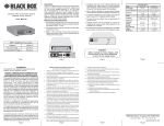
1
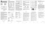
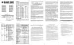
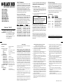
ABOUT THIS MANUAL: This document supports the FlexPoint 10FL/T models that are listed in the beginning of this user manual. Please refer to the serial number label on the bottom of the 10FL/T for the model number. This revision incorporates the following improvements to the 10FL/T: 1. 10FL/T operates in Link Propagate mode: A port of the 10FL/T transmits a Link signal only when receiving a Link at the other port of the 10FL/T. LMC212A-MM-R3 LMC212AE-MM-R3 LMC212A-SM-R3 LMC212AE-SM-R3 LMC212A-13MM-R3 LMC212AE-13MM-R3 LMC212A-SM-LH-R3 LMC212AE-SM-LH-R3 LMC212A-MM-SC-R2 LMC212AE-MM-SC-R2 FlexPoint ™ Overview and Description: 10FL/T CUSTOMER Order toll-free in the U.S.: Call 877-877-BBOX SUPPORT (outside U.S. call 724-746-5500) INFORMATION FREE technical support 24 hours a day, 7 days a week; Call 724-746-5500 or fax 724-746-0746 Mailing address: Black Box Corporation, 1000 Park Drive, Lawrence, PA 15055-1018 Web site: www.blackbox.com E-mail: [email protected] SPECIFICATIONS: Protocol: Connectors & Cables: Twisted Pair UTP: Fiber: Multimode: Single-mode: Supported Distances: Twisted Pair UTP: MM 850 nm fiber: MM 1310 nm fiber: SM 1310 nm fiber: SM 1310 nm LH fiber: SM 1550 nm XLH fiber: SM 1550 nm SLH fiber: Dimensions / Weight: Power: Environmental: Temperature: Humidity: IEEE802.3,10Base-FL, 10Base-T RJ45, Category 5 or higher SC, ST or MT-RJ 50/125, 62.5/125,100/140µm 9/125µm 100m/328 ft. 2km/1.2 mi./6,560 ft. 5km/3.1 mi./16,400 ft. 15km/9.3 mi./49,200 ft. 40km/24.9 mi./131,472 ft. 85km/52.8 mi./278,784 ft. 110km / 68.4 mi. / 361,152 ft. W:3.0"xD:4.0"xH:1.0" / 2 lb. 9 VDC / 350 mA 0 to 40 degrees C 0-90% (non-condensing) The FlexPoint 10FL/T media converter provides 10BaseFL single-mode (SM) or multimode (MM) fiber to 10Base-T twisted pair (UTP) media conversion. The 10FL/T is compliant with the IEEE 802.3 standards. It features a pair of ST, SC or MT-RJ fiber connectors and an EIA/TIA 568 RJ45 UTP connector. The following FlexPoint 10FL models are supported: Model Fiber Type Distance LMC212A-MM-R3 850nm,MM,ST 2km / 6,556 ft. LMC212AE-MM-R3 850nm,MM,ST 2km / 6,556 ft. LMC212A-SM-R3 1310nm,SM,ST 20km / 12.4 mi. LMC212AE-SM-R3 1310nm,SM,ST 20km / 12.4 mi. LMC212A-13MM-R3 1310nm,MM,ST 5km / 16,390 ft. LMC212AE-13MM-R3 1310nm,MM,ST 5km / 16,390 ft. LMC212A-SM-LH-R3 1310nm,SM,ST 40km / 24.9 mi. LMC212AE-SM-LH-R3 1310nm,SM,ST 40km / 24.9 mi. LMC212A-MM-SC-R2 850nm,MM,SC 2km / 6,556 ft. LMC212AE-MM-SC-R2 850nm,MM,SC 2km / 6,556 ft. TRADEMARKS All applied-for and registered trademarks are the property of their respective owners. FEDERAL COMMUNICATIONS COMMISSION AND CANADIAN DEPARTMENT OF COMMUNICATIONS RADIO FREQUENCY INTERFERENCE STATEMENTS This equipment generates, uses, and can radiate radio frequency energy and if not installed and used properly, that is, in strict accordance with the manufacturer’s instructions, may cause interference to radio communication. It has been tested and found to comply with the limits for a Class A computing device in accordance with the specifications in subpart J of Part 15 of FCC rules, which are designed to provide reasonable protection against such interference when the equipment is operated in a commercial environment. Operation of this equipment in a residential area is likely to be cause interference, in which case the user at his own expense will be required to take whatever measures may be necessary to correct the interference. Changes or modifications not expressly approved by the party responsible for compliance could void the user’s authority to operate the equipment. This digital apparatus does not exceed the Class A limits for radio noise emission from digital apparatus set out in the Radio Interference Regulation of the Canadian Department of Communications. Le présent appareil numérique n’émet pas de bruits radioélectriques dépassant les limites applicables aux appareils numéirques de las classe A prescrites dans le Règlement sur le brouillage radioélectrique publié par le ministère des Communications du Canada. The 10FL/T automatically supports half-duplex and full-duplex operations. It also supports switch-selectable straight-through or crossed RJ45 UTP wiring. Power Adapter Notice: 1. When used in a stand-alone configuration, this product is intended to be used only with a Listed Direct Plug-In Power Unit marked “Class 2” and rated at 9VDC, 1 Amp. 2. This product should always be used only with its enclosed Power Unit. WARNING! Before plugging the Power Adapter to any wall outlet or AC power source, verify that the power on the unit is appropriate for your AC line voltage source. Mounting and Cable Attachment: The FlexPoint 10FL/T can be individually wall-mounted using a wall-mounting kit, rack-mounted using a 5-position shelf, or inserted in a 14-position powerredundant FlexPoint Powered Chassis. When wallmounting or shelf-mounting, attach the power adapter unit. Attach the fiber cables to the FlexPoint 10FL ST connectors. Note that the FlexPoint transmit (Tx) must attach to the receive side on the device at the far end of the fiber; the receive (Rx) must attach to the transmit side. NORMAS OFICIALES MEXICANAS (NOM) ELECTRICAL SAFETY STATEMENT 1. Todas las instrucciones de seguridad y operación deberán ser leídas antes de que el aparato eléctrico sea operado. 2. Las instrucciones de seguridad y operación deberán ser guardadas para referencia futura. 3. Todas las advertencias en el aparato eléctrico y en sus instrucciones de operación deben ser respetadas. 4. Todas las instrucciones de operación y uso deben ser seguidas. 5. El aparato eléctrico no deberá ser usado cerca del agua— por ejemplo, cerca de la tina de baño, lavabo, sótano mojado o cerca de una alberca, etc. 6. El aparato eléctrico debe ser usado únicamente con carritos o pedelstales que sean recomendados por el fabricante. 7. El aparato eléctrico debe ser montado a la pared o al techo sólo como sea recomendado por el fabricante. 8. Servicio—El usuario no debe intentar dar servicio al equipo eléctrico más allá a lo descrito en las instrucciones de operación. Todo otro servicio deberá ser referido a personal de servicio calificado. 9. El aparato eléctrico debe ser situado de tal manera que su posición no interfiera su uso. La colocación del aparato eléctrico sobre una cama, sofá, alfombra or superficie similar puede bloquea la ventilación, no se debe colocar en libreros o gabinetes que impidan el flujo de aire por los orificios de ventilación. 10. El equipo eléctrico deber ser situado fuera del alcance de fuentes de calor como radiadores, registros de calor, estufas u ostros aparatos (incluyendo amplificadores) que producen calor. DIP-Switch Settings: UTP Crossover DIP-Switch: When connecting the UTP cable to a hub or switch, set the DIP-switch to straight-through “UTP to Hub/Switch” (factory setting). When connecting to a PC or workstation,set the DIP-switch to crossover “UTP to Workstation”. Disable Auto-Negotiation and manually set port speed to 10Mbps on the connecting UTP device. LED Indicators: LED Color Description Power On Polarity Yellow Yellow Fiber Link Green Fiber Rx UTP Link Green Green UTP Rx Green Power applied Polarity reversal was detected and corrected automatically Operational device detected at the far end of fiber Received data on fiber line Operational device detected at the far end of UTP Received data on the UTP line ©Copyright 1999-2006. Black Box Corporation. All rights reserved. 1000 Park Drive z Lawrence, PA 15055-1018 724-746-5500 z Fax 724-746-0746 11. El aparato eléctrico deberá ser connectado a una fuente de poder sólo del tipo descrito en el instructivo de operación, o como se indique en el aparato. 12. Precación debe ser tomada de tal manera que la tierra fisica y la polarización del equipo no sea eliminada. 13. Los cables de la fuente de poder deben ser guiados de tal manera que no sean pisados ni pellizcados por objetos colocados sobre o contra ellos, poniendo particular atención a los contactos y receptáculos donde salen del aparato. 14. El equipo eléctrico debe ser limpiado únicamente de acuerdo a las recomendaciones del fabricante. 15. En caso de existir, una antena externa deberá ser localizada lejos de las lineas de energia. 16. El cable de corriente deberá ser desconectado del cuando el equipo no sea usado por un largo periodo de tiempo. 17. Cuidado debe ser tomado de tal manera que objectos liquidos no sean derramados sobre la cubierta u orificios de ventilación. 18. Servicio por personal calificado deberá ser provisto cuando: A: El cable de poder o el contacto ha sido dañado; u B: Objectos han caído o líquido ha sido derramado dentro del aparato; o C: El aparato ha sido expuesto a la lluvia; o D: El aparato parece no operar normalmente o muestra un cambio en su desempeño; o E: El aparto ha sido tirado o su cubierta ha sido dañada. 040-01004-R31C 08/06 SPECIFICATIONS: Protocol: Connectors & Cables: Twisted Pair UTP: Fiber: Multimode: Single-mode: Supported Distances: Twisted Pair UTP: MM 850 nm fiber: MM 1310 nm fiber: SM 1310 nm fiber: SM 1310 nm LH fiber: SM 1550 nm XLH fiber: SM 1550 nm SLH fiber: Dimensions / Weight: Power: Environmental: Temperature: Humidity: IEEE802.3,10Base-FL, 10Base-T RJ45, Category 5 or higher SC, ST or MT-RJ 50/125, 62.5/125,100/140µm 9/125µm 100m/328 ft. 2km/1.2 mi./6,560 ft. 5km/3.1 mi./16,400 ft. 15km/9.3 mi./49,200 ft. 40km/24.9 mi./131,472 ft. 85km/52.8 mi./278,784 ft. 110km / 68.4 mi. / 361,152 ft. W:3.0"xD:4.0"xH:1.0" / 2 lb. 9 VDC / 350 mA 0 to 40 degrees C 0-90% (non-condensing) TRADEMARKS All applied-for and registered trademarks are the property of their respective owners. FEDERAL COMMUNICATIONS COMMISSION AND CANADIAN DEPARTMENT OF COMMUNICATIONS RADIO FREQUENCY INTERFERENCE STATEMENTS This equipment generates, uses, and can radiate radio frequency energy and if not installed and used properly, that is, in strict accordance with the manufacturer’s instructions, may cause interference to radio communication. It has been tested and found to comply with the limits for a Class A computing device in accordance with the specifications in subpart J of Part 15 of FCC rules, which are designed to provide reasonable protection against such interference when the equipment is operated in a commercial environment. Operation of this equipment in a residential area is likely to be cause interference, in which case the user at his own expense will be required to take whatever measures may be necessary to correct the interference. Changes or modifications not expressly approved by the party responsible for compliance could void the user’s authority to operate the equipment. This digital apparatus does not exceed the Class A limits for radio noise emission from digital apparatus set out in the Radio Interference Regulation of the Canadian Department of Communications. Le présent appareil numérique n’émet pas de bruits radioélectriques dépassant les limites applicables aux appareils numéirques de las classe A prescrites dans le Règlement sur le brouillage radioélectrique publié par le ministère des Communications du Canada. ABOUT THIS MANUAL: LMC212A-MM-R3 LMC212AE-MM-R3 LMC212A-SM-R3 LMC212AE-SM-R3 LMC212A-13MM-R3 LMC212AE-13MM-R3 LMC212A-SM-LH-R3 LMC212AE-SM-LH-R3 LMC212A-MM-SC-R2 LMC212AE-MM-SC-R2 FlexPoint™ 10FL/T CUSTOMER Order toll-free in the U.S.: Call 877-877-BBOX SUPPORT (outside U.S. call 724-746-5500) INFORMATION FREE technical support 24 hours a day, 7 days a week; Call 724-746-5500 or fax 724-746-0746 Mailing address: Black Box Corporation, 1000 Park Drive, Lawrence, PA 15055-1018 Web site: www.blackbox.com E-mail: [email protected] This document supports the FlexPoint 10FL/T models that are listed in the beginning of this user manual. Please refer to the serial number label on the bottom of the 10FL/T for the model number. This revision incorporates the following improvements to the 10FL/T: 1. 10FL/T operates in Link Propagate mode: A port of the 10FL/T transmits a Link signal only when receiving a Link at the other port of the 10FL/T. Overview and Description: The FlexPoint 10FL/T media converter provides 10BaseFL single-mode (SM) or multimode (MM) fiber to 10Base-T twisted pair (UTP) media conversion. The 10FL/T is compliant with the IEEE 802.3 standards. It features a pair of ST, SC or MT-RJ fiber connectors and an EIA/TIA 568 RJ45 UTP connector. The following FlexPoint 10FL models are supported: Model Fiber Type Distance LMC212A-MM-R3 850nm,MM,ST 2km / 6,556 ft. LMC212AE-MM-R3 850nm,MM,ST 2km / 6,556 ft. LMC212A-SM-R3 1310nm,SM,ST 20km / 12.4 mi. LMC212AE-SM-R3 1310nm,SM,ST 20km / 12.4 mi. LMC212A-13MM-R3 1310nm,MM,ST 5km / 16,390 ft. LMC212AE-13MM-R3 1310nm,MM,ST 5km / 16,390 ft. LMC212A-SM-LH-R3 1310nm,SM,ST 40km / 24.9 mi. LMC212AE-SM-LH-R3 1310nm,SM,ST 40km / 24.9 mi. LMC212A-MM-SC-R2 850nm,MM,SC 2km / 6,556 ft. LMC212AE-MM-SC-R2 850nm,MM,SC 2km / 6,556 ft. NORMAS OFICIALES MEXICANAS (NOM) ELECTRICAL SAFETY STATEMENT 1. Todas las instrucciones de seguridad y operación deberán ser leídas antes de que el aparato eléctrico sea operado. 2. Las instrucciones de seguridad y operación deberán ser guardadas para referencia futura. 3. Todas las advertencias en el aparato eléctrico y en sus instrucciones de operación deben ser respetadas. 4. Todas las instrucciones de operación y uso deben ser seguidas. 5. El aparato eléctrico no deberá ser usado cerca del agua— por ejemplo, cerca de la tina de baño, lavabo, sótano mojado o cerca de una alberca, etc. 6. El aparato eléctrico debe ser usado únicamente con carritos o pedelstales que sean recomendados por el fabricante. 7. El aparato eléctrico debe ser montado a la pared o al techo sólo como sea recomendado por el fabricante. 8. Servicio—El usuario no debe intentar dar servicio al equipo eléctrico más allá a lo descrito en las instrucciones de operación. Todo otro servicio deberá ser referido a personal de servicio calificado. 9. El aparato eléctrico debe ser situado de tal manera que su posición no interfiera su uso. La colocación del aparato eléctrico sobre una cama, sofá, alfombra or superficie similar puede bloquea la ventilación, no se debe colocar en libreros o gabinetes que impidan el flujo de aire por los orificios de ventilación. 10. El equipo eléctrico deber ser situado fuera del alcance de fuentes de calor como radiadores, registros de calor, estufas u ostros aparatos (incluyendo amplificadores) que producen calor. 11. El aparato eléctrico deberá ser connectado a una fuente de poder sólo del tipo descrito en el instructivo de operación, o como se indique en el aparato. 12. Precación debe ser tomada de tal manera que la tierra fisica y la polarización del equipo no sea eliminada. 13. Los cables de la fuente de poder deben ser guiados de tal manera que no sean pisados ni pellizcados por objetos colocados sobre o contra ellos, poniendo particular atención a los contactos y receptáculos donde salen del aparato. 14. El equipo eléctrico debe ser limpiado únicamente de acuerdo a las recomendaciones del fabricante. 15. En caso de existir, una antena externa deberá ser localizada lejos de las lineas de energia. 16. El cable de corriente deberá ser desconectado del cuando el equipo no sea usado por un largo periodo de tiempo. 17. Cuidado debe ser tomado de tal manera que objectos liquidos no sean derramados sobre la cubierta u orificios de ventilación. 18. Servicio por personal calificado deberá ser provisto cuando: A: El cable de poder o el contacto ha sido dañado; u B: Objectos han caído o líquido ha sido derramado dentro del aparato; o C: El aparato ha sido expuesto a la lluvia; o D: El aparato parece no operar normalmente o muestra un cambio en su desempeño; o E: El aparto ha sido tirado o su cubierta ha sido dañada. 040-01004-R31C 08/06 The 10FL/T automatically supports half-duplex and full-duplex operations. It also supports switch-selectable straight-through or crossed RJ45 UTP wiring. Power Adapter Notice: 1. When used in a stand-alone configuration, this product is intended to be used only with a Listed Direct Plug-In Power Unit marked “Class 2” and rated at 9VDC, 1 Amp. 2. This product should always be used only with its enclosed Power Unit. WARNING! Before plugging the Power Adapter to any wall outlet or AC power source, verify that the power on the unit is appropriate for your AC line voltage source. Mounting and Cable Attachment: The FlexPoint 10FL/T can be individually wall-mounted using a wall-mounting kit, rack-mounted using a 5-position shelf, or inserted in a 14-position powerredundant FlexPoint Powered Chassis. When wallmounting or shelf-mounting, attach the power adapter unit. Attach the fiber cables to the FlexPoint 10FL ST connectors. Note that the FlexPoint transmit (Tx) must attach to the receive side on the device at the far end of the fiber; the receive (Rx) must attach to the transmit side. DIP-Switch Settings: UTP Crossover DIP-Switch: When connecting the UTP cable to a hub or switch, set the DIP-switch to straight-through “UTP to Hub/Switch” (factory setting). When connecting to a PC or workstation,set the DIP-switch to crossover “UTP to Workstation”. Disable Auto-Negotiation and manually set port speed to 10Mbps on the connecting UTP device. LED Indicators: LED Color Description Power On Polarity Yellow Yellow Fiber Link Green Fiber Rx UTP Link Green Green UTP Rx Green Power applied Polarity reversal was detected and corrected automatically Operational device detected at the far end of fiber Received data on fiber line Operational device detected at the far end of UTP Received data on the UTP line ©Copyright 1999-2006. Black Box Corporation. All rights reserved. 1000 Park Drive z Lawrence, PA 15055-1018 724-746-5500 z Fax 724-746-0746