1
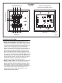
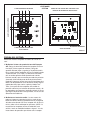
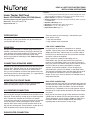
READ & SAVE THESE INSTRUCTIONS!
INSTALLATION INSTRUCTIONS
Home Theater Wall Panel
Model: CPHT200WH (White) CPHT200 (Black)
Mounting: Mounts on double gang electrical box
Dimensions: 45⁄8" H x 49⁄16" W x 15⁄16" D
Depth behind wall: 7⁄16"
INTRODUCTION
NuTone Home Theater Wall Panel, allows you to connect
the speakers in your home theater set up conveniently to
your Audio/Video (A/V) Receiver.
Features:
• For connecting the Front left and right, Rear left and right and center
channel speakers including a sub-woofer in a home theater set up
• Input Terminals: Accepts up to 14 AWG wires
• Output Terminals: Via speaker push type terminals which accept up
to 14 AWG wires
• Impedance Matching: None
• Mounting: Standard Double gang electrical box
• Dimensions: 45⁄8" H x 49⁄16" W x 15⁄16" D
• Depth Behind Wall: Appx. 7⁄16"
There are two ways of connecting a sub-woofer to your
home theater set up:
1. Low level connection
2. High (speaker level) connection
MOUNTING
LOW LEVEL CONNECTION:
Designed to be mounted on a double gang electrical box.
Choose a convenient location to mount your electrical box
close to where your stereo amplifier (A/V Receiver) will be
located. Refer to installation instructions sheet of the
electrical gang box for mounting the box. Refer to Figure 1
for connections.
Has provisions to connect a sub-woofer to an external
amplifier. Connect the passive sub-woofer wires to the SubWoofer terminal block. Connect one end, an RCA cable to
the RCA jack on the front face of the and connect the other
end of the cable to the amplifier.
CONNECTING SPEAKERS WIRES
At the back you will see terminal blocks for connecting your
speaker wires. Remove about 1/4" of insulation from each
speaker wire. Loosen the screw on each terminal block
using a small screwdriver and insert the speaker wires into
these terminal blocks, observing polarity. It is a good idea to
attach identifying labels on each wire.
MOUNTING THE FRONT PANEL
Gently insert the wires into the electrical gang box and
mount the front panel using the screws provided.
A/V RECEIVER CONNECTION
Connect the amplifier left and right front channel speaker
wires to the left and right front terminals on the front face of
the panel. These terminals accept up to 14 AWG of speaker
wires. Connect the amplifier left and right rear speaker
channel wires to the left and right rear terminals on the front
face of the panel. Connect the amplifier center channel
speaker wires to the center channel speaker terminals on
the front face of the panel. These terminals accept up to 14
AWG of speaker wires. Always observe polarity.
SUB-WOOFER CONNECTION
Note: If you have a powered sub-woofer such as
ES4110PSL, then you will connect the RCA cable from
panel to the “Sub-Woofer” RCA jack on the A/V receiver. If
you have passive sub-woofer, then you will need to connect
the RCA cable to an external preamplifier and power
amplifier. A convenient method is to use the high level
connection with a passive sub-woofer as described below.
The low level connection works well with either the low level
or the high level connection if you have a powered subwoofer. In this case, you may need to use shielded wires to
keep noise level low.
HIGH LEVEL CONNECTION:
Connect the front (main) left and right speaker wires from the
A/V Receiver to the Input Side (that says From Amplifier) left
and right terminals of the sub-woofer. Connect the Output
Side (that says To Speakers) left and right speaker wires to
the front left and right speaker terminals of the home theater
wall panel.
Now, you will also need a large screen television and either
a DVD player or Stereo VCR for your home theater system.
These components are not shown in Figure 1. Refer to the
instruction sheets of these components for information
regarding how to connect them in your set up.
TO AMPLIFIER/RECEIVER
HOME THEATER WALL PANEL
CPHT200WH
CPHT200
CONNECT SPEAKER WIRES TO
TO AMPLIFIER/RECEIVER
THE RESPECTIVE TERMINAL BLOCKS
REAR VIEW
TO AMPLIFIER/RECEIVER
FRONT VIEW
TERMINAL
BLOCK
FIGURE 1
TESTING THE SYSTEM
There are two ways of testing your home theater system.
1. Using your A/V Receiver’s Test Tone: Keep the volume
control on the A/V Receiver at some low setting (1/4th of
its maximum position). Keep the tone controls (Bass and
Treble) at their mid position. On most A/V Receivers
there is a button called “Test Tone”. If you select this
button, you will hear a hissing type of sound (called white
or pink noise) coming from the Main Front Left, Center,
Main Front Right and Rear (Surround) speakers in that
order. This sound sequence will keep repeating itself until
you defeat the Test Tone button. (Most A/V Receivers will
also allow you to increase or decrease the volume of the
Center Channel speaker and Rear speakers with respect
to the Main speaker). If no sound is heard from any
speaker(s), check the Troubleshooting Guide.
2. Using a sound source: The other method of testing your
system is to play music from a source such as a CD
player. Make sure you have selected “CD” player on the
A/V Receiver. Play music. You should hear sound from
your speakers. (Note: read the operating instructions that
came with Receiver carefully. Most Receivers cut off
sound to the Center Channel speaker if they are in
Stereo mode or Bypass mode).
TROUBLESHOOTING GUIDE
Symptom
Possible Cause
Possible Remedy
1. No sound from either speaker.
1. Improper source selected at amplifier.
2. Mute button pressed.
3. Wrong speaker output selected A or B.
4. Amplifier shuts off because of short circuit.
1. Select proper source.
2. Defeat Mute button.
3. Select proper position on A/B switch.
4. Check all wires and remove the short. Check
proper operation of Amplifier/Receiver.
2. Sound from only one speaker.
1. There is missing connection.
2. Balance control on amplifier turned all the way to
left or right.
1. Check all wires and make all connections.
2. Set the control to mid position.
3. Low bass sound.
1. Wrong polarity on one speaker.
1. Check polarity & rewire, if necessary.
4. Amplifier shuts off as volume is increased.
1. Amplifier is overloaded.
1. Short circuit in wire.
Check all wires & remove short.
Product specifications subject to change without notice.
4820 Red Bank Road, Cincinnati, Ohio 45227
Printed in China, Rev. 08/07/06, Part No. 61807
!
LEA Y GUARDE ESTAS INSTRUCCTIONES!
INSTRUCCIONES DE INSTALACIÓN
CaracterÌsticas:
• Para conectar los canales de los parlantes frontales y posteriores,
izquierdos y derechos, y el central en un sistema de cine en su casa.
Modelo: CPHT200WH (Blanco) CPHT200 (Negro)
• Terminales de entrada: Acepta alambres de hasta calibre 14.
• Terminales de salida: Mediante terminales de parlante tipo enchufe que
Montaje: Se monta en caja de electricidad de tándem de dos
aceptan alambres de hasta calibre 14.
unidades
Dimensiones: 45⁄8" (11,7 cm) de alto por 49⁄16" (11,6 cm) de ancho • Adaptación de impedancia: Ninguna.
• Montaje: Caja de electricidad estándar de tándem de dos unidades.
por 15⁄16" (3,3 cm) de profundidad
• Dimensiones: 4-5/8" (11,7 cm) de alto por 4-9/16" (11,6 cm) de ancho por
Profundidad detrás de la pared: 7⁄16" (1 cm)
1-5/16" (3,3 cm) de profundidad
• Profundidad detrás de la pared: 7/16" (1 cm)
Panel de pared para cine en su casa
INTRODUCCIÓN
El Panel de pared para cine en su casa y de NuTone la
permite conectar de forma conveniente los parlantes de su
systema de cine doméstico al receptor de audio y video
(A/V).
MONTAJE
El panel ha sido diseñado para montarlo sobre una caja de
electricidad de tándem de dos unidades. Escoja una
ubicación conveniente para montar la caja de electricidad
cerca de dónde estará ubicado el amplificador estéreo
(receptor A/V0. Vea las instrucciones de instalación de la
caja de electricidad para amarla apropiadamente. Vea la
figura 1 con respecto a las conexiones al panel.
CONEXIÓN DE CABLES DE LOS PARLANTES
En la parte posterior del panel verá bloques terminales para
conectar los cables de los parlantes. Quite aproximadamente
1/4" (1/2 cm) de aislante de los cables del parlante e
insértelos en estas terminales, observanco la polaridad. Es
recomendable poner etiquetas de identificación en cada
cable.
Hay dos maneras de conectar un altavoz de ultragraves al
sistema de cine en su casa:
1. Conexión de nivel bajo
2. Conexión de nivel alto (nivel del parlante)
CONEXIÓN DE NIVEL BAJO:
Brinda la posibilidad de conectar un altavoz de untragraves a
un amplificador externo. Conecte los cables pasivos del
altavoz de ultragraves al bloque de terminales del mismo.
Conecte un extremo, un cable RCA al enchufe RCA del
frente del y conecte el otro extremo del cable al amplificador.
Nota: Si tiene un altavoz de ultragraves potenciado, como el
ES4110PSL, debe conectar el cable RCA del panel al
enchufe RCA “Sub-Woofer” en el receptor A/V. Si tiene un
altavoz de ultragraves pasivo, debe conectar el cable RCA
del a un preamplificador externo y amplificador potenciado.
Un buen método es utilizar la conexión de nivel alto con un
altavoz de ultragraves pasivo como se describe más
adelante. La conexión funciona bien tanto con la conexión
baja como con la alta si se dispone de un altavoz de
ultragraves potenciado. En dicho caso, es posible que deba
utilizar cables blindados para disminuir el ruido.
MONTAJE DEL PANEL FRONTAL
Inserte con cuidado los cables en la caja de electricidad de
tándem de dos unidades y arme el panel frontal con los
tornillos disponibles.
CONEXIÓN DEL RECEPTOR A/V
Conecte los cables del amplificador de los canales de los
parlantes frontales izquierdo y derecho a las terminales
designadas de izquierda frontal y derecha frontal en la parte
frontal del panel del. Dichas terminales aceptan alambres de
hasta calibre 14. Conecte los cables del amplificador de los
canales de los parlantes posteriores izquierdo y derecho a
las terminales designadas de izquierda posterior y derecha
posterior en la parte fronmtal del panel del. Dichas terminales
aceptan alambres de hasta calibre 14. Conecte los cables
del amplificador del canal del parlante central a la terminale
designada central en la parte frontal del panel del. Dicha
terminal acepta alambres de hasta calibre 14. Siempre
observe la polaridad.
CONEXIÓN DEL ALTAVOZ DE ULTRAGRAVES
CONEXIÓN DE NIVEL ALTO:
Conecte los cables de los parlantes frontales (principales)
izquierdo y derecho desde el receptor A/V a las terminales
izquierda y derecha del lado de entrada (que dice “From
Amplifier” [desde el amplificador]) del altavoz de ultragraves.
Conecte los cables de los parlantes izquierdo y derecho del
lado de salida (que dice “To Speakers” [a los parlantes] a las
terminales de los parlantes izquierdo y derecho del panel de
pared para cine en su casa modelo.
Para el sistema de cine en su casa también necesitará un
televisor de pantalla grande y un reproductor de DVD o un
videograbador estéreo. Dichos componentes no se muestran
en la figura 1. Vea las instrucciones de los mismos para
informarse sobre cómo conectarlos a su sistema
PANEL DE PARED PARA CINE EN SU CASA
CPHT200WH
CPHT200
A AMPLIFICADOR O RECEPTOR
CONECTAR LOS CABLES DEL PARLANTE A LOS
A AMPLIFICADOR O RECEPTOR
BLOQUES DE TERMINALES RESPECTIVOS
BLOQUE DE TERMINALES
A AMPLIFICADOR O RECEPTOR
VISTA FRONTAL
VISTA POSTERIOR
FIGURA 1
PREUBA DEL SISTEMA
Existen dos maneras de probar el sistema de cine en su
casa.
1. Mediante el sistema de prueba de tono del Receptor
A/V: Ponga el control del volumen del receptor A/V en un
nivel bajo (1/4 de su posición máxima). Ponga los
controles del tono (bajos y agudos) en la posición media.
En la mayoría de los receptores A/V hay un botón llamado
“Prueba de tono” (Test Tone). Si selecciona este botón,
oirá un sonido como de silbido (denominado “sonido
blanco o rosado”) que se transmite por todos los parlantes
(sorround); dicho sonido parte desde el parlante frontal
izquierdo, sigue en el central, pasa por el frontal derecho y
termina en los posteriores. Esta secuencia sonora seguirá
repitiéndose hasta que vuelva a oprimir el botón Test
Tone. (La mayorÌa de los receptores A/V también le
permiten subir o bajar el volumen del parlante central y de
los posteriores con respecto al parlante principal.) Si no se
oye ningún sonido de uno o más parlantes, vea la Guía de
Soluciones de Problemas.
2. Mediante una fuente de sonido: La otra manera de
probar el sistema es reproducir música a través de una
fuente de sonido, como un reproductor de CD. Asegúrese
de haber seleccionado “CD” en el receptor A/V. Al tocar la
música, debe salir el sonido por los parlantes. (NOTA: La
mayoría de los receptores anulan el sonido del canal
central si están en modalidad estéreo o “bypass”. Lea las
instrucciones de operación que vinieron con el receptor.
GUÍA DE SOLUCIÓN DE PROBLEMAS
Síntoma
Posible causa
Posible solución
1. No sale sonido de ningún parlante.
1. Se ha seleccionado una fuente equivocada en la
amplificador.
2. Se ha oprimido el botón silenciador (Mute).
3. Se ha seleccionado mal la salida del parlante,
A o B.
4. El amplificador se apaga debido a un corto
circuito.
1. Selecciones la fuente correcta.
2. Desactive el botón silenciador.
3. Seleccione la posición en el interruptor A/B.
4. Revise todos los cables y elimine el corto
circuito. Verifique que el amplificador/receptor
funcione correctamente.
2. Sale sonido de un solo parlante.
1. Falta una conexión.
2. El control del amplificador está puesto totalmente
a la izquierda o la derecha.
1. Revise todos los cables y haga las conexiones
necesarias.
2. Ponga el control en la posición media.
3. Poco sonido de graves.
1. Error de polaridad en uno de los parlantes.
1. Verifique la polaridad y vuelva a conectar los
cables, de ser necesario.
4. El amplificador se apaga cuando se sube
el volumen.
1. El amplificador está sobrecargado
1. Puede haber un corto circuito. Revise todos los
cables y elimínelo.
Las especificaciones del producto están sujetas a cambio sin previo aviso.
4820 Red Bank Road, Cincinnati, Ohio 45227
Impreso en China, Rev. 08/07/06, Part No. 61807