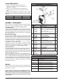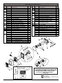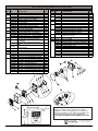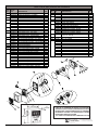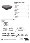
1
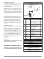
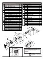
Procedure for Calibration
1. For the most accurate calibration, install the meter in the
application. Fill a container to a known volume with the
liquid to be measured.
2. If indicated amount does not match known volume, insure
pump is off and pressure relieved, then remove seal screw
(item 23) and turn calibration screw (item 21)
counterclockwise to reduce indicated amount or clockwise
to increase the amount. A full turn will change the indicated
amount by approximately 0.1 Gal. (0.4L).
Reinstall seal screw.
3. Repeat step 1 and 2 until calibration is acceptable.
SERIES 800C
METER
Owner's Operation & Safety Manual
Models 806C, 807C
SAFETY INSTRUCTIONS
OPERATING INSTRUCTIONS
To ensure safe and efficient operation, it is essential to read
each of these warnings and precautions, and to follow all
instructions listed in this manual.
1. Improper use or installation of this product can cause
serious bodily injury or death.
2. DO NOT smoke near meter or use meter near an open flame
when dispensing flammable fluids. Fire could result.
3. Do not exceed 50 PSI / 3.5 BARS line pressure.
4. CAUTION: Do not install additional foot valve or check valve
during installation without pressure relief valve. Cracking
may result.
5. This product should not be used for fluid transfer into aircraft.
6. This product is not suited for use with fluids for human
consumption, including potable water.
For accurate measurement, meter and piping must always be
filled with liquid and free of air. Meter should be calibrated per
instructions in this manual prior to its use.
1. Stop flow of liquid.
2. Reset meter to “0”.
3. Meter is ready for use. Start flow of liquid. Do not exceed
50 PSI line pressure.
MAINTENANCE
Meter should operate maintenance free. However, certain
liquids can dry out while in the meter housing, causing the
meter to stop. If this happens, meter should be thoroughly
cleaned (see instructions below).
Cleaning Instructions:
Run a flushing fluid through meter. For a more thorough
cleaning, disassemble meter per “ASSEMBLY /
DISASSEMBLY” section, “Meter Chamber Assembly”
subsection. Rinse all meter components. Recalibrate meter
following calibration instructions above.
Storage:
If meter is to be stored for a period of time, clean thoroughly. This
will help protect meter from damage.
INSTALLATION
Meters are furnished for horizontal piping, left to right flow,
unless otherwise specified. Use oil and gasoline resistant
pipe compound on all threaded joints. Flow ports can be
located in any of four positions for horizontal or vertical piping.
1. If fluid flow is left to right, install meter.
2. If fluid flow is other than left to right, determine direction of fluid
flow.
3. Lay meter dial face down on a clean flat surface.
4. Arrow mark on meter housing indicates fluid flow direction.
5. Remove four screws (item 20).
6. Lift meter housing (item 19) and chamber assembly (item
26) and rotate together to desired flow direction.
CAUTION: Chamber opening must face towards inlet port of
meter.
7. Replace four screws (item 20).
8. Install meter.
TROUBLESHOOTING GUIDE
Counter is reading high or low:
Check calibration and recalibrate if necessary. Check for air
in product and repair air leaks. Measuring chamber or gears
could be sticking. Correct by cleaning or replacing internal
metering components.
Shaft seal leakage:
Possible causes are dirty or damaged seals. Correct by
cleaning o-ring and seat area or replacing seal.
Gasket leakage:
Correct loose gasket by tightening joints. Clean dirty gaskets
and seat area. Replace damaged gaskets.
Low flow capacity:
Clean clogged meter chamber; clean or replace screens and
filters in piping.
Meter body cracks:
Install pressure relief valve to allow high pressure to bleed back
to tank.
Nutating disc breaks:
Avoid flow surge by putting shut-off valve on outlet of meter;
place meter as close as possible to pump; keep piping full of
liquid.
CALIBRATION
The Fill-Rite Series 800C meters can be calibrated for either U.S.
gallons or liters. Calibration is required after disassembly, when
metering a different fluid, or after significant wear. Depending on
the model, Series 800C meters are factory calibrated in either
U.S. gallons or liters using mineral spirits.
Meter calibration can be easily changed by using the calibration
procedure noted. A container of KNOWN volume will be needed
for the calibration procedure. It is recommended that the
container’s volume be at least five gallons or larger.
1
FLUID COMPATIBILITY
800C SERIES STRAINER KIT
The 800C is compatible with the following fluids:
•Diesel Fuel, Gasoline, Kerosene, Mineral Spirits,
Heptane, and Hexane
The 800C is NOT compatible with the following fluids:
•Bleach, Hydrochloric Acid, Ink, Sulfuric Acid, and Salt
Water
If in doubt about compatibility of a specific fluid, contact supplier
of fluid to check for any adverse reactions to the following wetted
materials.
Ryton
EPDM
Teflon®
Aluminum
Flourocarbon
Nickel
Stainless Steel
Buna N
* Item 1 not
included in kit.
ASSEMBLY / DISASSEMBLY
Meter consists of a chamber housing, measuring chamber,
gear train, counter assembly and cover. Meter can be
completely disassembled without disturbing piping.
Counter Assembly
For access to counter assembly, remove reset knob (item 3) by
grasping edges and pulling firmly. Remove two screws (item
29) and lift counterface (item 2) and cover (item 1) off. Remove
two screws (item 13) to extract counter (item 4). Reassemble
by reversing procedure.
Meter Chamber Assembly
To expose meter chamber assembly, tilt the meter at least
slightly face down, so that no parts fall out when removing meter
housing. Remove the four screws (item 20), then remove meter
housing (item 19). Meter chamber assembly consists of upper
and lower chambers, a nutating disc and seal gasket.
Reassemble by reversing procedure.
If replacement of any components of the meter chamber
assembly is required, the complete assembly must be
replaced due to the precise method of its construction. This
assures a proper fit and a correctly operating chamber.
Gear Train and Seal
To disassemble gear train and seal, remove gear frame (item
12) by prying slightly. Remove cluster gear (item 10) and
washer (item 11) from shaft (item 9). Remove drive gear (item
8) and washers (item 7) by rotating and pulling drive gear.
Remove O-ring seal (item 6).
When reassembling seal, lubricate O-ring liberally with oil or
petroleum jelly and replace in cover. Place washer on drive gear
shaft. Carefully rotate and push shaft through O-ring and cover
to prevent damage to O-ring. Shaft must then be guided into
pinion bevel (item 28) if counter has not been removed. Replace
remaining parts to complete assembly by reversing
disassembly procedure.
ITM. PART
NO. NO.
1
2
3
4
5
6
7
8
9
800G1325
800G2727
800G1387
800G1998
800G2705
800G1440
800F4360
800F4362
800F4361
800F4380
800F4381
800F4350
800F4320
800F4340
800F4343
800F4342
800F4337
800F4339
800F4338
800F4390
800F4400
700F2800
700F2801
TH18
TH18T
TH18X418
TH18TX418
DESCRIPTION
QTY.
806C, 1", U.S. Gallon
1
806C, 1", U.S. Gallon, Nickel Plated
Opt.
806C, 1", U.S. Gallon, Teflon® Coated Opt.
806C, 1" BSP, Liters
Opt.
806C, 1" BSP, Liters, Nickel Plated
Opt.
806C, 1" BSP, Liters, Teflon® Coated Opt.
Cover
1
Cover, Nickel Plated
Opt.
Cover, Teflon® Coated
Opt.
O-Ring (-131), Buna-N
1
O-Ring (-131), Viton
Opt.
Screen
1
5/16-18 x 7/8 SHCS
2
Strainer Housing
1
Strainer Housing, Nickel Plated
Opt.
Strainer Housing, Teflon® Coated
Opt.
Strainer Housing, BSP Threads
Opt.
Strainer Housing, BSP Threads, Teflon Opt.
Strainer Housing, BSP Threads, Nickel Opt.
1 x 2 Pipe Nipple
1
1" Street Elbow
1
O-Ring (-218)
1
O-Ring (-218), Viton
Opt.
Strainer Kit, 1", U.S. (Includes items 2-6, 9)
Strainer Kit, 1", U.S.,Teflon® Ctd. (items 2-9)
Strainer Kit, 1" BSP (Includes items 2-6, 9)
Strainer Kit, 1" BSP,Teflon Ctd. (items 2-6, 9)
800B/800C SERIES REPAIR PARTS KITS
PART
NO.
800KTG2540
800KTG2541
REPAIR
800KTG2542
Meters needing repair should be taken to an authorized repair
shop for service. Meters must be thoroughly triple-rinsed before
being taken in for repair.
800KTG2543
800KTG2579
PRIOR TO SERVICE, ADHERE TO FOLLOWING INSTRUCTIONS:
Meters must be triple-rinsed and accompanied by a note
indicating the chemicals which have been pumped through
the unit. Meters not adhering to these specifications may be
refused service.
2
DESCRIPTION
Repair Kit, U.S. Gallon (Standard Seals)
(Includes items 6-12, 18, 22, 24-26, 28)
Repair Kit, U.S. Gallon (Viton Seals)
(Includes items 6-12, 18, 22, 24-26, 28)
Repair Kit, Liter (Standard Seals)
(Includes items 6-12, 18, 22, 24-26, 28)
Repair Kit, Liter (Viton Seals)
(Includes items 6-12, 18, 22, 24-26, 28)
Repair Kit, U.S. Gallon, (EPDM Seals)
(Includes items 6-12, 18, 22, 24-26, 28)
800C METER PARTS LIST
ITM.
NO.
1
2
3
4
5
6
7
8
9
10
11
12
13
18
19
PART
NO.
800G2246
800G0208
800G0241
800G8870
800F4080
800F4081
800G2246
800G2247
800G2248
800F4191
800F4033
800F3980
800F3845
800F3846
800F4185
800F3820
800F3841
800F3843
800F3541
800F3830
800G2250
900F4007
700F2800
700F2801
800G2601
800G2236
800G2237
800G2238
800G2242
800G2243
800G2244
800G2255
800G2256
800G2257
DESCRIPTION
ITM.
NO.
20
21
22
QTY.
Counter Cover
Counter Face, U.S. Gallon
Counter Face, Liter
Knob
Counter - U.S. Gallon
Counter - Liter
Meter Cover
Meter Cover, Nickel Plated
Meter Cover, Teflon® Coated
O-ring (5-106) Fluorocarbon
O-ring (5-106) EPDM
Washer
Drive Gear (70T) - U.S. Gallon
Drive Gear (84T) - Liter
Drive Gear (73T) - Imperial Gallon
Shaft, Cluster Gear
Cluster Gear (22T/67T) - U.S. Gallon
Cluster Gear (10T/67T) - Liter
Cluster Gear (19T/67T) - Imperial Gallon
Washer
Gear Frame Assembly
#8-32 x 5/16 PHMS ACR II
O-ring (-218), Buna-N ( 800A, 700A/B)
O-ring (-218), Fluorocarbon (800A, 700A/B)
O-ring (-218), EPDM (800A, 700A/B)
3/4 Inlet - 3/4 Outlet Housing
3/4 Inlet - 3/4 Outlet Hsg., Nickel Plated
3/4 Inlet - 3/4 Outlet Hsg., Teflon® Coated
1 Inlet - 1 Outlet U.S. Housing
1 Inlet - 1 Outlet U.S. Hsg., Nickel Plated
1 Inlet - 1 Outlet U.S. Hsg., Teflon® Coated
1 Inlet - 1 Outlet BSPT Housing
1 Inlet - 1 Outlet BSPT Hsg., Nickel Plated
1 Inlet - 1 Outlet BSPT Hsg., Teflon® Coated
6"
150 mm
PART
NO.
800G8892
800F4463
800F4449
800F3389
800F4440
800F4036
800F4034
800F4010
800F4011
800F4032
800G2262
800G2599
800G2600
800G2531
DESCRIPTION
QTY.
5/16-18 x 1 HWTRS
4
Calibration Screw (Includes Item 24)
1
O-ring (-012) Fluorocarbon
1
O-ring (-012) EPDM
Opt.
23
Seal Screw
1
24
O-ring (-008) (Included w/Item 21) Fluorocarb 1
O-ring (-008), EPDM
Opt.
25
O-ring (-156), Buna-N
1
O-ring (-156), Fluorocarbon
Opt.
O-ring (-156), EPDM
Opt.
26
Meter Chamber Assembly - Buna-N
1
Meter Chamber Assembly - Fluorocarbon
Opt.
Meter Chamber Assembly - EPDM
Opt.
27
Meter Chamber Assembly, Buna-N
1
(Includes Items 12 & 26)
28 800F3959 Pinion Bevel
1
29 35F1397
#4 x 3/8 PHSMS
2
30 800G2532 Cover Assembly - U.S. Gallon
1
800G2533 Cover Assy. - U.S. Gallon - Nickel Plated
Opt.
800G2534 Cover Assy. - U.S. Gallon - Teflon® Coated
Opt.
800G2535 Cover Assembly - Liter
Opt.
800G2536 Cover Assembly - Liter, Nickel Plated
Opt.
800G2537 Cover Assembly - Liter, Teflon® Coated
Opt.
800G2544 Cover Assembly - Imperial Gallon
Opt.
800G2765 Cover Assy. - U.S. with EPDM Seal
Opt.
800G2778 Cover Assy. - U.S. Nickel with EPDM Seal
Opt.
800G2900 Cover Assembly - Liter with EPDM Seal
Opt.
*These parts are in the 800C Series Repair Parts Kit..
1
1
Opt.
1
1
Opt.
1
Opt.
Opt.
1
Opt.
2
1
Opt.
Opt.
1
1
Opt.
Opt.
1
1
2
Opt.
Opt.
Opt.
1
Opt.
Opt.
Opt.
Opt.
Opt.
Opt.
Opt.
Opt.
6"
150 mm
8"
200 mm
3
WHEN ORDERING REPAIR PARTS, BE SURE TO GIVE
REPLACEMENT PART NUMBER, DATE OF MANUFACTURE
AND METER SERIES NUMBER. THIS WILL ENSURE THAT
THE CORRECT REPLACEMENT PART IS SUPPLIED.
TOLL FREE CUSTOMER SERVICE NUMBER
800 634 2695
800F9146 rev 8
Procedimiento para efectuar el ajuste.
1. Llenar el contenedor con volumen conocido.
2. Si la cantidad indicada no es la correcta, quitar tornillo de
retén (artículo 23) hacer girar el tornillo de ajuste (artículo
21) en sentido anti-horario para reducir la cantidad
indicada y en sentido horario para aumentarla. Instale
tornilla de retén.
3. Repita el paso 1 y 2 hasta que la calibración sea
aceptable.
SERIES 800C
Medidor
INSTRUCCIONES DE OPERACIÓN
Manual de operación y seguridad
Modelos 806C, 807C
Para efectuar un ajuste cuidadoso y evitar que se malogre
el contador, el contador y la tuber’a deben estar siempre
llenos con líquidos y sin burbujas de aire.
1. Pare el flujo de líquido.
2. Poner en cero el contador.
3. El medidor está listo para el uso. Empiece el flujo de
líquido. No superar la presión de l’nea de 50 PSI/3.5 bar.
INSTRUCCIONES DE SEGURIDAD
Para garantizar un empleo eficiente y seguro, es esencial
y seguro, leer y ejecutar cada una de las siguientes
precauciones:
1. El uso o instalación impropia del producto, pueden
causar heridas graves o incluso la muerte.
2. NO fumar cerca del contador y no utilizarlo cerca
de llamas durante la distribución de fluidos
inflamables. Podr’a provocarse un incendio.
3. No superar la presión de l’nea de 50 PSI/3.5 bar.
4. ADVERTENCIA: No use válvulas de retención
adicionales o válvulas depedalamenos que tengan
válvulas de presión adecuadas.
5. Este producto no debe usarse para transferir líquidos
a aeronaves.
6. Este producto no es adecuado para usarse con líquidos
para consumo humano, incluida el agua potable.
MANTENIMIENTO
El medidor no debiera necesitar mantenimiento alguno. Sin
embargo, alguno líquidos pueden secarse dentro del medidor
bloqueándolo, en ese caso es necesario limpiar el medidor
por completo.
Instrucciones para la limpieza:
Hacer circular un fluido en el medidor. Para conseguir una
limpieza más completa, desmontar el contador, siguiendo
la sección MONTAJE/DESMONTAJE, sub-sección “Montaje
de la cámara del medidor”. Enjuagar todos los
componentes del medidor. Reajustar el contador según las
instrucciones para el ajuste que se han indicado
anteriormente.
Almacenamiento:
En caso que el medidor deba almacenarse durante un
cierto período de tiempo, limpiarlo completamente. Esto lo
protegerá contra posibles averías.
INSTALACION
Los medidores que se suministran son adecuados para
tuber’as horizontales, con flujo de izquierda a derecha, salvo
indicaciones contrarias. La entrada del flujo puede quedar
ubicada en cualquiera de las 4 posiciones para las tuberías
horizontales y verticales y para cualquier dirección del flujo.
1. Si el líquido fluye de izquierda a derecha, instale el medidor.
2. Si el líquido fluye en otra dirección aparte de izquierda a
derecha, determine la dirección del flujo del líquido.
3. Coloque la esfera del medidor boca abajo sobre una
superficie plana y limpia.
4. La flecha en la caja del medidor indica la dirección del
flujo del líquido.
5. Quitar los cautro tornillos (artículo 20).
6. Levante la caja del medidor (artículo 19) y el conjunto de la
cámara (artículo 26) y gírelos juntos hasta la dirección de
flujo deseada.
ADVERTENCIA: La abertura de la cámara debe estar
hacia la lumbrera de entrada del medidor.
7. Volver a colocar los cuatro tornillos (artículo 20).
8. Instale el medidor.
GUIA PROBLEMAS
Lectura contador alta o baja:
Recalibrar contador si necesario. Localizar y reparar fugas de
aire en sistema. Limpiar o sustituir componentes contador
internas.
Fuga junta eje contador:
Limpiar retén y cavidad retén. Sustituya retén.
Fuga junta:
Apretar juntas. Limpiar retén y cavidad retén. Sustituya
retén
Capacidad baja:
Limpiar cámara medidor. Limpiar pantalla.
El cuerpo del medidor se agrieta:
Instale la válvula de alivio de presión para purgar la presión
alta de vuelta al tanque.
El disco oscilante se rompe:
Para evitar el aumento brusco del flujo coloque una válvula
de cierre en la salida del medidor; coloque el medidor lo
más cerca posible de la bomba; mantenga la tubería llena
de líquido.
AJUSTE
Es necesario ajustar inmediatamente después de la
instalación, del desmontaje, después de un desgaste
notable o cuando se utilice un fluido con viscosidad diferente.
Los medidores serie 800C, llegan calibrados de fábrica,
miden gasolina por litros.
COMPATIBILIDAD DE FLUIDOS
La contador 800C es compatible con los siguientes fluidos:
• Diesel, Gasolina, Queroseno, Espíritus Minerales,
Heptane, y Hexane
NO USE la contador 800C con los siguientes fluidos:
• Decolorante, Acido Clorhídrico, Tinta, Sulfúrico Acido, y
Agua salada
Si tiene duda sobre la compatibilidad de un fluido específico,
póngase en contacto con el proveedor para saber si tiene
reacciones adversas con los materiales húmedos mostrados.
El ajuste en metros puede ser efectuado con facilidad
siguiendo el procedimiento de ajuste que se indica a
continuación. Para efectuar el ajuste, es necesario un
contenedor de pruebas o con volumen conocido. Se
recomienda que el volumen del recipiente sea de por lo
menos cinco galones o mayor.
4
Ryton
EPDM
Teflon®
Aluminum
Flourocarbon
Nickel
800C SERIES KIT de FILTRO
Stainless Steel
Buna N
MONTAJE / DESMONTAJE
El medidor se compone del alojamiento de la cámara, de la
cámara de medición, de la serie de engranajes, del
conjunto y de la cobertura del contador. El contador puede
ser desmontado por completo sin tocar las tuberías, o bien
puede ser desmontado parcialmente según las
necesidades.
Montaje del medidor
Para proceder a montar el medidor, quitar el pulsador de
puesta en cero (artículo 3), aferrando los extremos y tirando
fuerte. Quitar los dos tornillos (artículo 29) y extraer la parte
anterior del medidor (artículo 2). Quitar dos tornillos
(artículo 13) para poder extraer el contador (artículo 4), volver
a montar siguiendo el procedimiento inverso.
Montaje de la cámara del medidor
Descripción del montaje de la cámara del medidor; inclinar
ligeramente el contador volviéndolo hacia abajo, de manera
que ninguna pieza pueda caer durante la extracción del
alojamiento del contador. Quitar cuatro tornillos (artículo 20),
luego quitar el alojamiento del medidor (artículo 19). El
conjunto de cámara del medidor se compone de cámara
superior e inferior, de un disco variable y de la
empaquetadura hermética. Volver a montar, siguiendo el
procedimiento inverso.
En el caso que sea necesario substituir los componentes
del conjunto de la cámara del medidor deberá ser
substituido todo el conjunto, a causa de la precisión del
método de su construcción. Ello garantiza una justa
adecuación y el correcto funcionamiento de la cámara.
Serie de engranajes y dispositivo hermético
Para desmontar la serie de engranajes y el dispositivo
hermético, quitar la estructura del engranaje (artículo 12),
moviéndola ligeramente con una palanca. Quitar el grupo de
engranajes (artículo 10) y la arandela (artículo 11). Quitar el
engranaje conductor (artículo 8) y las arandelas (artículo 7)
haciendo girar y tirando el engranaje conductor. Quitar el
dispositivo hermético de los O-ring (artículo 6).
Cuando se vuelve a montar el dispositivo hermético, lubricar
los O-ring con aceite o vaselina y substituir la cobertura.
Colocar la arandela en el eje del engranaje conductor.Hacer
girar y empujar el eje a través del O-ring, y cubrir con
cuidado para evitar que se malogre el O-ring. El eje debe
ser guiado en el piñón cónico (artículo 28) si el contador no
ha sido quitado. Substituir el resto de las partes hasta
terminar el montaje siguiendo el procedimiento inverso.
* El artículo 1 no
está incluido en
kit.
ART. PIEZA
NO. NO.
1
2
3
4
5
6
7
8
9
800G1325
800G2727
800G1387
800G1998
800G2705
800G1440
800F4360
800F4362
800F4361
800F4380
800F4381
800F4350
800F4320
800F4340
800F4343
800F4342
800F4337
800F4339
800F4338
800F4390
800F4400
700F2800
700F2801
TH18
TH18T
TH18X418
TH18TX418
DESCRIPCIÓN
CTD.
806C, 1", U.S. Galón
1
806C, 1", U.S. Galón, Nickel Plated
Opt.
806C, 1", U.S. Galón, Teflon Coated
Opt.
806C, 1" BSP, Litros
Opt.
806C, 1" BSP, Litros, Nickel Plated
Opt.
806C, 1" BSP, Litros, Teflon® Coated Opt.
Tapa
1
Tapa, Nickel Plated
Opt.
Tapa, Teflon® Coated
Opt.
Junta tórica (-131), Buna-N
1
Junta tórica (-131), Viton
Opt.
Cedazo
1
5/16-18 x 7/8 SHCS
2
Caja de filtro
1
Caja de filtro, Nickel Plated
Opt.
Caja de filtro, Teflon® Coated
Opt.
Caja de filtro, BSP Threads
Opt.
Caja de filtro, BSP Threads, Teflon®
Opt.
Caja de filtro, BSP Threads, Nickel
Opt.
Niple de 1 x 2
1
Codo urbano de 1"
1
Junta tórica (-218)
1
Junta tórica (-218), Viton
Opt.
Kit de filtro, 1", U.S. (Incluido art. 2-6, 9)
Kit de filtrot, 1", U.S., Teflon® Ctd. (art. 2-9)
Kit de filtro, 1" BSP (Incluido art. 2-6, 9)
Kit de filtro, 1" BSP, Teflon® Ctd. (art. 2-6, 9)
800B/800C SERIES KITS de REPARACIÓN
PIEZA
NO.
800KTG2540
REPARACION
800KTG2541
Los medidores que deben ser reparados, deberán ser
llevados a un centro de asistencia o deberán ser devueltos a
la fábrica para su mantenimiento. Los medidores deberán
ser enjuagados por lo menos tres veces antes de ser
reparados.
800KTG2542
800KTG2543
800KTG2579
ANTES DEL SERVICIO, RESPETE LAS INSTRUCCIONES
SIGUIENTES:
Los medidores deben enjuagarse tres veces y enviarse
con una nota indicando los productos químicos que fueron
bombeados a través de la unidad. A los medidores que no
se ajustan a estas especificaciones se les puede negar
servicio.
5
DESCRIPCIÓN
Kit de Reparación, U.S. Galón (Standard Retén)
(Incluido art. 6-12, 18, 22, 24-26, 28)
Kit de Reparación, U.S. Galón (Viton Retén)
(Incluido art. 6-12, 18, 22, 24-26, 28)
Kit de Reparaciónt, Litros (Standard Retén)
(Incluido art. 6-12, 18, 22, 24-26, 28)
Kit de Reparación, Litros (Viton Retén)
(Incluido art. 6-12, 18, 22, 24-26, 28)
Kit de Reparación, U.S. Galón, (EPDM Retén)
(Incluido art. 6-12, 18, 22, 24-26, 28)
LISTA DE PIEZAS MEDIDOR DE SERIE 800C
ART.
NO.
1
2
9
PIEZA
NO.
800G2246
800G0208
800G0241
800G8870
800F4080
800F4081
800G2246
800G2247
800G2248
800F4191
800F4033
800F3980
800F3845
800F3846
800F4185
800F3820
10
800F3841
3
4
5
6
7
8
800F3843
800F3541
11
12
13
18
19
800F3830
800G2250
900F4007
700F2800
700F2801
800G2601
800G2236
800G2237
800G2238
800G2242
800G2243
800G2244
800G2255
800G2256
800G2257
ART.
NO.
20
21
22
DESCRIPCIÓN
CTD.
Tapa del contador
1
Etiqueta de la pantalla, U.S. Galónes
1
Etiqueta de la pantalla, Litros
Opt.
Perilla
1
Extraer el contador - U.S. Galónes
1
Contador - Litros
Opt.
Tapa de medidor
1
Tapa de medidor, Nickel Plated
Opt.
Tapa de medidor, Teflon® Coated
Opt.
Junta tórica (5-106) Fluorocarbon
1
Junta tórica (5-106) EPDM
Opt.
Arandela
2
Engranaje motriz (70T) - U.S. Galónes
1
Engranaje motriz (84T) - Litros
Opt.
Engranaje motriz (73T) - Imperial Galónes
Opt.
Eje de agrupamiento de angranajes
1
Engranaje de agrupamiento (22T/67T) 1
U.S. Galónes
Engranaje de agrupamiento (10T/67T) Opt.
Litros
Engranaje de agrupamiento (19T/67T) Opt.
Imperial Galónes
Arandela
1
Ensamble la estructura de engranaje
1
#8-32 x 5/16 PHMS ACR II
2
Junta tórica (-218), Buna-N ( 800A, 700A/B) Opt.
Junta tórica (-218), Fluorocarbon (800A, 700A Opt.
Junta tórica (-218), EPDM (800A, 700A/B)
Opt.
3/4 Entrada - 3/4 Caja del salida
1
3/4 Entrada - 3/4 Caja del salida, Nickel Pltd. Opt.
3/4 Entrada - 3/4 Caja del salida, Teflon® Ctd Opt.
1 Entrada - 1 Caja del salida U.S.
Opt.
1 Entrada - 1 Caja del salida U.S., Nickel Pltd Opt.
1 Entrada - 1 Caja del salida U.S., Teflon® Ct Opt.
1 Entrada - 1 Caja del salida BSPT
Opt.
1 Entrada - 1 Caja del salida BSPT, Nickel Plt Opt.
1 Entrada - 1 Caja del salida BSPT, Teflon® C Opt.
6"
150 mm
23
24
25
26
27
28
29
30
Estas
6"
150 mm
8"
200 mm
6
PIEZA
NO.
800G8892
800F4463
800F4449
800F3389
800F4440
800F4036
800F4034
800F4010
800F4011
800F4032
800G2262
800G2599
800G2600
800G2531
DESCRIPCIÓN
CTD.
5/16-18 x 1 HWTRS
4
Tornillo de ajuste (Incluido Art. 24)
1
Junta tórica (-012) Fluorocarbon
1
Junta tórica (-012) EPDM
Opt.
Tornillo de retén
1
Junta tórica (-008) (Incluido w/Art. 21) Fluoroc 1
Junta tórica (-008), EPDM
Opt.
Junta tórica (-156), Buna-N
1
Junta tórica (-156), Fluorocarbon
Opt.
Junta tórica (-156), EPDM
Opt.
El conjunto de la cámara - Buna-N
1
El conjunto de la cámara - Fluorocarbon
Opt.
El conjunto de la cámara - EPDM
Opt.
El conjunto de la cámara, Buna-N
1
(Incluido Art. 12 & 26)
800F3959 Pinión cónico
1
35F1397
#4 x 3/8 PHSMS
2
800G2532 Conjunto de tapa - U.S. Galón
1
800G2533 Conjunto de tapa. - U.S. Galón - Nickel Pltd. Opt.
800G2534 Conjunto de tapa - U.S. Galón - Teflon® Ctd. Opt.
800G2535 Conjunto de tapa - Litro
Opt.
800G2536 Conjunto de tapa - Litro, Nickel Plated
Opt.
800G2537 Conjunto de tapa - Litro, Teflon® Coated
Opt.
800G2544 Conjunto de tapa - Litro - Imperial Galón
Opt.
800G2765 Conjunto de tapa - U.S. with EPDM retén
Opt.
800G2778 Conjunto de tapa - U.S. Nickel EPDM retén Opt.
800G2900 Conjunto de tapa - Litro with EPDM retén
Opt.
partes están en la Reparación de la Serie 800C Kit.
Cuando se solicitan piezas de recambio, es necesario
indicar el nœmero de las piezas que se desean
substituir, su fecha de producción y el nœmero de
serie de la bomba. De este modo se garantizará una
correcta substitución de la pieza de recambio.
TOLL FREE CUSTOMER SERVICE NUMBER 800 634 2695
800F9146 rev 8
Procédure de calibration
1. Pour une calibration plus précise, utiliser le compteur
dans la configuration réelle. Remplir un récipient avec
une quantité connue du liquide à mesurer.
2. Si la quantité indiquée ne correspond pas à la quantité
connue, vérifier que la pompe est éteinte et qu’elle soit hors
pression, ensuite retirer la vis d’étanchéité (réf. 23) et
tourner la vis de calibration (réf. 21) dans le sens antihorlogique pour diminuer la quantité ou dans le sens
horlogique pour l’augmenter. Un tour complet modifiera la
quantité de +/- 0,1 Gal (0,4 L). Réinstaller la vis d’étanchéité.
3. Répétez le point 1 et 2 jusqu’à ce que la calibration soit
acceptable.
SERIES 800C
Compteur
Manuel d'utilisation et sécurité
Modèles 806C, 807C
MISE EN MARCHE
INSTRUCTIONS DE SECURITE
Pour une mesure précise et pour éviter tout dommage, le
compteur et la ligne doivent toujours être remplis de liquide
et sans air.
1. Arrêter le flux de liquide.
2. Remettez le compteur à zéro.
3. Le compteur est prêt à l’emploi. Commencer le flux de
liquide. Ne pas dépasser une pression de 50PSI/3,5 bar.
Afin d’assurer une utilisation sûre et efficace, il est essentiel
de lire et d’observer chacun des avertissements suivants:
1. Une mauvaise utilisation ou installation de ce produit peut
causer des blessures corporelles graves voire la mort.
2. Ne pas fumer à proximité de la pompe et ne pas l’utiliser
près d’une flamme.
3. Ne pas dépasser une pression de 50PSI/3,5 bar.
4. ATTENTION: Ne pas utiliser de de clapets de retenue ou
clapets de pied additionnels á moins qu'ils n'aient des
soupapes de pression incorporées.
5. Ce produit ne doit pas être utilisé pour transfé du fluide dans
un avion.
6. Ce produit ne convient pas à une utilisation avec des
fluides pour la consommation humaine, y compris l’eau
potable.
ENTRETIEN
Le compteur doit normalement fonctionner sans entretien.
Certains liquides peuvent cependant sécher dans la chambre
de mesure et bloquer le compteur. Si cela se produit, nettoyez
le complètement.
Instructions de nettoyage
Rincez abondamment le compteur. Pour un nettoyage complet,
démontez le compteur en suivant les instructions de la section
“ASSEMBLAGE/DESASSEMBLAGE”. Rincez tous les
composants. Recalibrez selon les instructions ci-dessus.
Stockage
Si le compteur doit être stocké pour une longue période,
nettoyez-le. Il sera ainsi protégé de tout dommage.
INSTALLATION
Les compteurs sont prévus, par défaut, pour un écoulement
horizontal de la gauche vers la droite. Les raccords d’entrée et
sortie peuvent toutefois être positionnés dans chacune des
quatre positions horizontale et verticale, et ce pour n’importe
quelle direction d’écoulement.
1. Si l’écoulement du fluide va de gauche à droite, installez
le compteur.
2. Si l’écoulement du fluide est autre que de gauche à
droite, déterminez sa direction.
3. Posez le compteur avec son cadran sur une surface plane
et propre.
4. Flèche de marquage sur le boîtier du compteur indiquant
le sens d’écoulement du fluide.
5. Retirez les quatre vis (réf. 20).
6. Levez le boîtier du compteur (réf. 19) et l’ensemble de
chambre (réf. 26), et tournez-les ensemble dans le sens
d’écoulement voulu.
ATTENTION: L’ouverture de chambre doit faire face à
l’ouverture d’entrée du compteur.
7. Replacez les quatre vis (réf. 20).
8. Installer le compteur.
GUIA PROBLEMAS
Lecture du compteur trop haute ou basse:
Recalibrer le compteur. Trouver et réparer la fuite dans le
système. Nettoyer ou remplacer les composants internes.
Fuite sur arbre:
Nettoyer le joint et son siège. Remplacer le joint.
Fuite des joints:
Serrer les joints. Nettoyer le joint et son siège. Remplacer le
joint.
Capacité réduite:
Nettoyer la chambre de mesure.
Fissures du corps de compteur:
Installez une soupape de décharge pour permettre à la forte
pression de se purger dans le réservoir.
Cassures du disque oscillant:
Évitez les pointes de débit en plaçant une soupape d’arrêt
sur la sortie du compteur; placez le compteur aussi près
que possible de la pompe; gardez la tuyauterie remplie de
liquide.
CALIBRATION
COMPATIBILTÉ DES FLUIDES
La calibration du compteur est nécessaire après un
démontage, une usure significative ou à l’occasion de mesures
de fluide de viscosité différente. Les compteurs de la série
800C sont calibrés en usine pour mesurer de l’essence en
litres.
La calibration peut aisément être modifiée par la procédure
ci-après. Un réservoir étalon ou plus simplement un réservoir
de volume connu est requis. Il est recommandé que la capacité
du conteneur fasse 19 litres (5 gallons) ou plus.
Séries 800C sont compatibles avec les fluides suivants:
•Mazout, Essence, Kérosène, Combustibles minéraux,
Heptane et Hexane
Séries 800C ne sont PAS compatibles avec les fluides
suivants:
•Acétone, Benzène, Eau de Javel, Acide Chlorhydrique,
Encre, et Toluène
En cas de doute sur la compatibilité d'un fluide spécifique avec
les pompes, contactez le fournisseur du fluide pour vérifier s'il
y'a des réactions adverses résultant du contact.
7
Ryton
EPDM
Teflon®
Aluminum
Flourocarbon
Nickel
800C SERIES KIT DE FILTRE
Stainless Steel
Buna N
ASSEMBLAGE/DESASSEMBLAGE
Le compteur est composé d’une cavité de mesure, d’une
chambre de mesure, d’une transmission, d’un assemblage
compteur et d’un boîtier. Le compteur peut être partiellement
ou complêtement démonté sans perturber la ligne de pompage.
Assemblage compteur
Pour accéder à l’assemblage compteur, retirez le bouton de
remise à zéro en le tirant fermement. Le bouton est retenu par
un circlip. Déserrez les deux vis (réf. 13), et retirez le boîtier du
compteur. Retirez les deux vis (réf. 29) pour déposer la plaque
frontale. Retirez les deux vis (réf. 13) et ensuite le compteur luimême (réf. 4). Rèassemblez par la procèdure inverse.
* L’article 1
n’est pas inclus
dans le kit
RÉF. PIÉCE
NO. NO.
Chambre de mesure
Pour extraire la chambre de mesure, faites tourner le compteur
tête vers le bas de sorte qu’aucune pièce ne tombe lors de
l’ouverture de la cavité de mesure. Retirez les quatre vis (réf.
20) et ensuite la cavité de mesure (réf. 19). La chambre de
mesure consiste en une chambre supérieure, une chambre
inférieure, un disque oscillant et un joint. Réassembler par la
procédure inverse.
Si le remplacement d’une pièce de la chambre de mesure
s’avère nécessaire, l’assemblage complet devra être remplacé
en raison de la précision de son montage.
1
2
3
4
5
6
Transmission et joint
Pour démonter la transmission et son joint, retirez le cadre de
transmission (réf. 12) en tirant avec douceur. Retirez la roue
dentée primaire ( réf. 10) et sa rondelle (réf. 11). Retirez la roue
dentée secondaire (réf. 8) et ses rondelles (réf. 7) en la faisant
tourner et en la tirant. Retirez le joint O-ring (réf. 6).
Lors du remontage, lubrifiez généreusement le joint O-ring avec
de la graisse et remettez le en place. Placez la rondelle sur
l’arbre de transmission secondaire. Introduisez cet arbre dans
le joint O-ring par de légères rotations en prenant soin de ne
pas l’endommager. L’arbre doit être correctement guidé dans
le pinion (réf. 28) si le compteur n'a pas été démonté. Replacer
les pièces restantes pour terminer l’assemblage en suivant la
procédure inverse.
7
8
9
800G1325
800G2727
800G1387
800G1998
800G2705
800G1440
800F4360
800F4362
800F4361
800F4380
800F4381
800F4350
800F4320
800F4340
800F4343
800F4342
800F4337
800F4339
800F4338
800F4390
800F4400
700F2800
700F2801
TH18
TH18T
TH18X418
TH18TX418
PIÉCE
NO.
800KTG2540
800KTG2541
AVANT UNE INTERVENTION, SUIVEZ LES INSTRUCTIONS
SUIVANTES:
Les compteurs doivent être rincés trois fois et accompagnés
d’une note indiquant les produits chimiques qui ont été
pompés au travers de l’unité. Les compteurs pour lesquels
ces instructions n’auront pas été suivies seront refusés
pour le service.
QTÉ
806C, 1", U.S. Gallon
1
806C, 1", U.S. Gallon, Nickelé
Opt.
806C, 1", U.S. Gallon, Teflonné
Opt.
806C, 1" BSP, Litres
Opt.
806C, 1" BSP, Litres, Nickelé
Opt.
806C, 1" BSP, Litres, Teflonné®
Opt.
Couvercle
1
Couvercle, Nickelé
Opt.
Couvercle, Teflonné®
Opt.
Joint torique (-131), Buna-N
1
Joint torique (-131), Viton
Opt.
Filtre
1
5/16-18 x 7/8 SHCS
2
Corps de filtre
1
Corps de filtre, Nickelé
Opt.
Corps de filtre, Teflonné®
Opt.
Corps de filtre, BSP Threads
Opt.
Corps de filtre, BSP Threads,Teflonné Opt.
Corps de filtre, BSP Threads, Nickelé Opt.
Raccord 1 x 2"
1
Coude 1"
1
Joint torique (-218)
1
Joint torique (-218), Viton
Opt.
Kit filtre, 1", U.S. (Includes items 2-6, 9)
Kit filtre, 1", U.S., Teflonné® (items 2-9)
Kit filtre, 1" BSP (Includes items 2-6, 9)
Kit filtre, 1" BSP, Teflonné® (items 2-6, 9)
800B/800C SERIES
KIT DE RÉPARATION
REPARATION
En cas de réparation du compteur, adressez vous au
fabricant. Le compteur doit être complètement et
triplement rincé avant toute réparation.
DESCRIPTION
800KTG2542
800KTG2543
800KTG2579
8
DESCRIPTION
Kit de réparation, U.S. Gallon (Joints standard)
(Inclus réf. 6-12, 18, 22, 24-26, 28)
Kit de réparation, U.S. Gallon (Joints viton)
(Inclus réf. 6-12, 18, 22, 24-26, 28)
Kit de réparation,Litres (Joints standard)
(Inclus réf. 6-12, 18, 22, 24-26, 28)
Kit de réparation, Litres (Joints viton)
(Inclus réf. 6-12, 18, 22, 24-26, 28)
Kit de réparation, U.S. Gallon, (Joints EPDM)
(Inclus réf. 6-12, 18, 22, 24-26, 28)
800C LISTE DES PIÉCES DÉTACHÉES
RÉF. PIÉCE
NO. NO.
DESCRIPTION
1 800G2246 Couvercle de débitmètre
2 800G0208 Étiquette de l'afficheur, U.S. Gallon
800G0241 Étiquette de l'afficheur, Litre
3 800G8870 Bouton
4 800F4080 Débitmètre - U.S. Gallon
800F4081 Débitmètre - Litre
5 800G2246 Couvercle de compteur
800G2247 Couvercle de compteur, Nickelé
800G2248 Couvercle de compteur, Teflonné®
6 800F4191 O-ring (5-106) Fluorocarbure
800F4033 O-ring (5-106) EPDM
7 800F3980 Rondelle
8 800F3845 Pignon moteur (70T) - U.S. Gallon
800F3846 Pignon moteur (84T) - Litre
800F4185 Pignon moteur (73T) - Imperial Gallon
9 800F3820 Arbre de train d'engrenage
10 800F3841 Train d'engrenage (22T/67T) - U.S. Gallon
800F3843 Train d'engrenage (10T/67T) - Litre
800F3541 Train d'engrenage (19T/67T) - Imperial Gallon
11 800F3830 Rondelle
12 800G2250 Cadre de transmission
13 900F4007 #8-32 x 5/16 PHMS ACR II
18 700F2800 O-ring (-218), Buna-N ( 800A, 700A/B)
700F2801 O-ring (-218), Fluorocarbure (800A, 700A/B)
800G2601 O-ring (-218), EPDM (800A, 700A/B)
19 800G2236 3/4" Boîtier du compteur
800G2237 3/4" Boîtier du compteur, Nickelé
800G2238 3/4" Boîtier du compteur, Teflonné®
800G2242 1" Boîtier du compteur U.S.
800G2243 1" Boîtier du compteur U.S., Nickelé
800G2244 1" Boîtier du compteur U.S., Teflonné®
800G2255 1" Boîtier du compteur BSPT
800G2256 1" Boîtier du compteur BSPT, Nickelé
800G2257 1" Boîtier du compteur BSPT, Teflonné®
6"
150 mm
RÉF.
NO.
20
21
22
QTÉ.
1
1
Opt.
1
1
Opt.
1
Opt.
Opt.
1
Opt.
2
1
Opt.
Opt.
1
1
Opt.
Opt.
1
1
2
Opt.
Opt.
Opt.
1
Opt.
Opt.
Opt.
Opt.
Opt.
Opt.
Opt.
Opt.
23
24
25
26
27
28
29
30
PIÉCE
NO.
800G8892
800F4463
800F4449
800F3389
800F4440
800F4036
800F4034
800F4010
800F4011
800F4032
800G2262
800G2599
800G2600
800G2531
800F3959
35F1397
800G2532
800G2533
800G2534
800G2535
800G2536
800G2537
800G2544
800G2765
800G2778
800G2900
*Ces pièces sont
6"
150 mm
8"
200 mm
9
DESCRIPTION
5/16-18 x 1 HWTRS
Vis de calibration (Inclus réf. 24)
O-ring (-012) Fluorocarbure
O-ring (-012) EPDM
Joint Vis
O-ring (-008) (Inclus réf. 21) Flourocarbure
O-ring (-008), EPDM
O-ring (-156), Buna-N
O-ring (-156), Fluorocarbure
O-ring (-156), EPDM
Chambre de Compteur - Buna-N
Chambre de Compteur - Fluorocarbure
Chambre de Compteur - EPDM
Chambre de Compteur, Buna-N
(Inclus réf. 12 & 26)
Bevel des pignons
#4 x 3/8 PHSMS
Couvercle - U.S. Gallon
Couvercle - U.S. Gallon - Nickelé
Couvercle - U.S. Gallon - Teflonné®
Couvercle - Litre
Couvercle - Litre, Nickelé
Couvercle - Litre, Teflonné®
Couvercle - Imperial Gallon
Couvercle - U.S. EPDM Joint
Couvercle - U.S. Nickelé EPDM Joint
Couvercle - Litre EPDM Joint
dans le kit de réparation série 800C
QTÉ.
4
1
1
Opt.
1
1
Opt.
1
Opt.
Opt.
1
Opt.
Opt.
1
1
2
1
Opt.
Opt.
Opt.
Opt.
Opt.
Opt.
Opt.
Opt.
Opt.
LORS DE LA COMMANDE DE PIÈCES DE RECHANGE,
ASSUREZ-VOUS DE FOURNIR LA RÉFÉRENCE DE LA PIÈCE
DE RECHANGE, LA DATE DE FABRICATION ET LE NUMÉRO
DE SÉRIE DE LA POMPE. CECI ASSURE QUE LA BONNE
PIÈCE DE RECHANGE EST FOURNIE.
TOLL FREE CUSTOMER SERVICE NUMBER 800 634 2695
800F9146 rev 8
Kalibrierverfahren
1. Behälter bis auf ein bekanntes Volumen auffüllen.
2. Ist die angegebene Menge falsch, die Kalibrierschraube (Tiel 21)
entgegen dem Uhrzeigersinn drehen, um die angegebene
Menge zu reduzieren. Drehen Sie die Schraube im Uhrzeigersinn,
um die angegebene Menge zu erhähen.
3. Schritt 2 wiederholen, bis die Kalibrierung akzeptabel ist.
SERIES 800C
MESSGERÄTE
BEDIENUNGSANWEISUNGEN
Zwecks einer präzisen Messung und um zu verhindern, daß das
Meßgerät beschädigt wird, müssen Meßgerät und Leitungen stets
mit Flüssigkeit gefüllt und frei von Luft sein.
1. Halten Sie Ablauf der Flüssigkeit auf.
2. Meßgerät erneut auf “0” stellen.
3. Das Meßgerät ist betriebsbereit. Fangen Sie Ablauf der
Flüssigkeit an. Der Leitungsdruck darf 50 PSI/3, nicht
überschreiten.
Gebrauchsanweisung und
Sicherheitsvorschriften
Modells 806C, 807C
SICHERHEITSANWEISUNGEN
Um einen sicheren und wirksamen Betrieb zu
gewährleisten, ist es von wesentlicher Bedeutung, daß Sie sich
zunächst mit nachstehenden Warnungen und Vorsichtsmaßnahmen
vertraut machen.
1. Die unsachgemäße Verwendung bzw. Installation dieses
Gerätes kann zu ernsthaften Verletzungen bzw. sogar zum
Tode führen.
2. Das Rauchen in der Nähe des Meßgerätes ist UNTERSAGT.
Gleichfalls ist es verboten, beim Verteilen entflammbarer
Flüssigkeiten das Meßgerät in der Nähe einer offenen Flamme
einzusetzen, da dies einen Brand auslösen könnte.
3. Der Leitungsdruck darf 50 PSI/3,5 bar nichtüberschreiten.
4. VORSICHT: KEINE ZUSÄTZLICHEN BODEN-ODER
RÜCKSCHLAGVENTILE BEI INSTALLATION OHNE
SICHERHEITSVENTIL MONTIEREN. KANN RISSE IM GEHÄUSE
ODER IN DEN ROHRLEITUNGEN VERURSACHEN.
5. Dieses Produkt nicht zur Überführung von Kraftstoff in Flugzeuge
benutzen.
6. Dieses Produkt ist zur Verwendung für Flüssigkeiten,
einschließlich Trinkwasser, die von Menschen konsumiert
werden, nicht geeignet.
WARTUNG
Das Meßgerät sollte wartungsfrei funktionieren. Es kann jedoch
sein, daß bestimmte Flässigkeiten im Gehäuse des Meßgerätes
eintrocknen, wodurch das Meßgerät ausgeschaltet wird. Ist dies
der Fall, muß das Meßgerät gründlich gereinigt werden.
Anweisungen zur Reinigung
Lassen Sie eine Spülflüssigkeit durch das Meßgerät laufen. Wenn
Sie das Meßgerät gründlicher reinigen möchten, sollten Sie die im
Abschnitt “MONTAGE/DEMONTAGE”, Teilabschnitt “Montage der
Meßkammer” enthaltenen Anweisungen befolgen. Spülen Sie alle
Bestandteile des Meßgerätes ab. Meßgerät erneut entsprechend
den Kalibrieranweisungen kalibrieren.
Lagerung
Wenn das Meßgerät über einen bestimmten Zeitraum gelagert
werden soll, sollte es vorher gründlich gereinigt werden. Auf diese
Weise wird das Meßgerät vor etwaigen Beschädigungen bewahrt.
ANWEISUNGENZUR FEHLERANALYSE
Leck der Antriebswellendichtung:
Dichtung und Dichtungssitz reinigen. Dichtung ersetzen.
Dichtungsleck:
Verbindungsstücke festziehen. Dichtung und Dichtungssitz reinigen.
Dichtungs ersetzen.
Niedrige Kapazität:
Zählergehäuse reinigen. Filter reinigen.
Hohe oder niedrige Zählerziffer:
Luftverluste im System suchen und reparieren. Interne
Meßkomponente reinigen oder ersetzen.
Risse im Messinstrumentenkörper:
Ein Überdruckventil installieren, um überhöhten Druck in den Behälter
zurück fließen zu lassen.
Taumelscheibe bricht:
Durch ein Absperrventil am Messinstrumenten-Auslass einen
Überlauf vermeiden; das Messinstrument so nahe wie möglich zur
Pumpe platzieren; die Rohrleitungen mit Flüssigkeit gefüllt lassen.
INSTALLATION
Die Meßgeräte sind für horizontale Leitungen bestimmt, mit einer
Strömungsrichtung von links nach rechts (außer bei
anderslautenden Angaben). Die Strömungsanschlüsse können in
einer von vier Positionen für horizontale oder vertikale Leitungen
und für beide Strömungsrichtungen angebracht werden.
1. Wenn der Durchfluss von links nach rechts erfolgt, das
Messinstrument installieren.
2. Wenn der Flüssigkeitsdurchfluss anders als von links nach
rechts ist, die Durchflussrichtung der Flüssigkeit bestimmen.
3. Das Messinstrument mit der Anzeigeskala nach unten auf eine
saubere ebene Fläche legen.
4. Eine Pfeilmarkierung auf dem Messinstrumentengehäuse
kennzeichnet die Durchflussrichtung der Flüssigkeiten.
5. Entfernen Sie die 4 Schrauben (Tiel 20).
6. Das Messinstrumentengehäuse (Tiel 19) und die
Kammerbaugruppe (Tiel 26) anheben und zur gewünschten
Durchflussrichtung zusammendrehen.
ACHTUNG: Die Kammeröffnung muss in die Richtung des
Messinstrumenten-Einlasses zeigen.
7. Vier Schrauben erneut montieren.
8. Installieren Sie Meter.
Kompatible Flüssigkeiten
Die Serie 800C sind mit folgenden Flüssigkeiten kompatibel:
• Dieselkraftstoff, Benzin, Kerosin, Sulfatterpentin, Heptane
und Hexane
Die Serie 800C sind mit folgenden Flüssigkeiten NICHT kompatibel:
•Bleichmittel, hydrochloridhaltige Säure, Tinte, Schwefelsauer
Säure, und Salzwasser
Wenn Zweifel über die Kompatibilität mit einer speziellen Flüssigkeit
bestehen, wenden Sie sich an den Hersteller der Flüssigkeit und fragen
Sie nach nachteiligen Reaktionen mit den folgenden benetzten
Materialien.
KALIBRIERUNG
Die Kalibrierung ist bei der Installation, nach der Demontage, nach
beträchtlichem Verschleiß bzw. beim Messen einer Flüssigkeit mit
einer anderen Viskosität erforderlich. Die Meßgeräte der Reihe 800C
werden in der Fabrik kalibriert und dienen zur Messung von Benzin in
Litern.
Die Kalibrierung des Meßgerätes kann durch Befolgung des
untenstehenden Kalibrierverfahrens leicht geändert werden. Für
dieses Kalibrierverfahren ist ein Eichbehälter bzw. ein Behälter mit
bekanntem Volumeninhalt erforderlich. Es wird ein Behältervolumen
von mindestens 19 Liter oder mehr empfohlen.
Ryton
EPDM
Teflon®
10
Aluminum
Flourocarbon
Nickel
Stainless Steel
Buna N
MONTAGE/ DEMONTAGE
800C SERIES FILTERSATZ
Das Meßgerät besteht aus einem Kammergehäuse, einer Meßkammer,
einem Rädergetriebe, einem Zählersatz und einem Deckel. Das
Meßgerät kann entweder vollständig demontiert werden, ohne dabei
die Leitungen zu berühren, bzw. entsprechend den Bedürfnissen
teilweise demontiert werden.
Zählersatz
Um den Zählersatz zu erreichen, sollte die Drehknopf (Tiel 3) durch
Festhalten an den Rändern und kräftiges Ziehen entfernt werden.
Die Drehknopf wird durch eine Federklammer an Ort und Stelle
gehalten. Zwei Schrauben lösen (Tiel 13) und Deckel abnehmen. Um
die Zählerfrontplatte (Tiel 2) zu lösen, sollten zwei Schrauben (Tiel
29) abmontiert werden. Um den Zähler zu entfernen (Teil 4), sollten
zwei Schrauben (Tiel 13) entfernt werden. Die Montage erfolgt in
der umgekehrten Reihenfolge.
Montage der Meßkammer
Um die Meßkammer zu erreichen, sollten Sie das Meßgerät leicht mit
der Vorderseite nach unten halten, so daß beim Entfernen des
Gehäuses keine Einzelteile herausfallen. Entfernen Sie zunächst die
vier Schrauben (Pos. 20), montieren Sie daraufhin das Gehäuse ab
(Tiel 19). Die Meßkammer besteht aus einer oberen und unteren
Kammer, einer Taumelscheibe und einer Dichtungspackung. Die
Montage erfolgt in der entgegengesetzten Reihenfolge. Falls es
erforderlich sein sollte, einige Komponenten der Meßkammer zu
ersetzen, muß der vollständige Satz aufgrund der präzisen
Konstruktionsweise ausgetauscht werden. Auf diese Weise wird
ein korrekter Sitz und ein einwandfreier Betrieb der Kammer
gewährleistet.
*Pos. 1 nicht
eingeschlossen
in satz.
EINZELTEIL
TIEL NUMMER
1
2
Rädergetriebe und Dichtung
Um das Rädergetriebe und die Dichtung abzumontieren, sollte der
Rahmen des Zahnrades (Tiel 12) durch vorsichtiges Rütteln entfernt
werden.
Entfernen Sie den Schaltblock (Tiel 10) sowie den Dichtungsring
(Tiel 11). Entfernen Sie das Antriebszahnrad (Teil 8) sowie die
Dichtungsringe (Tiel 7), indem Sie das Antriebszahnrad drehen und
ziehen. Entfernen Sie die Packung des O-Rings (Tiel 6).
Bei der Montage der Dichtung sollte der O-Ring reichlich mit Öl oder
Rohvaseline geschmiert und erneut in den Deckel montiert werden.
Installieren Sie den Dichtungsring auf die Antriebsradwelle. Drehen
und drücken Sie die Welle vorsichtig durch den O-Ring und decken
Sie ab, um zu verhindern, daß der O-Ring beschädigt wird.
Die Welle muß daraufhin in die Ritzel geführt werden (Tiel 28), falls
der Zähler nicht entfernt wurde. Installieren Sie die restlichen Teile
in entgegengesetzter Reihenfolge, um die Montage zu
vervollständigen.
3
4
5
6
7
8
9
REPARATUR
Reparaturbedürftige Meßgeräte sollten zu einer anerkannten
Reparaturwerkstatt bzw. zur Fabrik gebracht werden. Vorher sollten die
Meßgeräte gründlich dreifach gespült werden.
800G1325
800G2727
800G1387
800G1998
800G2705
800G1440
800F4360
800F4362
800F4361
800F4380
800F4381
800F4350
800F4320
800F4340
800F4343
800F4342
800F4337
800F4339
800F4338
800F4390
800F4400
700F2800
700F2801
TH18
TH18T
TH18X418
TH18TX418
BESCREIBUNG
QTY.
806C, 1", U.S. Gallonen
1
806C, 1", U.S. Gallonen, NickelbeschtetOpt.
806C, 1", U.S. Gallonen, Teflon®besch Opt.
806C, 1" BSP, Liters
Opt.
806C, 1" BSP, Liters,Nickelbeschichtet Opt.
806C, 1" BSP, Liters,Teflonbeschichtet Opt.
Filterabdeckung
1
Filterabdeckung, Nickelbeschichtet
Opt.
Filterabdeckung, Teflonbeschichtet
Opt.
O-Ring (-131), Buna-N
1
O-Ring (-131), Viton
Opt.
Sieb
1
5/16-18 x 7/8 SHCS
2
Filterengehäuse
1
Filterengehäuse, Nickelbeschichtet
Opt.
Filterengehäuse, Teflonbeschichtet
Opt.
Filterengehäuse, BSP
Opt.
Filterengehäuse, BSP, Teflonbeschicht Opt.
Filterengehäuse, BSP, Nickelbeschicht Opt.
1 x 2 Innennippel
1
1" Krümmer
1
O-Ring (-218)
1
O-Ring (-218), Viton
Opt.
Filtersatz, 1", U.S. (Einschließen 2-6, 9)
Filtersatz, 1", U.S., Teflon (Einschließen 2-9)
Filtersatz, 1" BSP (Einschließen 2-6, 9)
Filtersatz, 1" BSP,Teflon(Einschließen 2-6, 9)
800B/800C SERIES REPARATURSATZ
EINZELTEIL
NUMMER
800KTG2540
800KTG2541
VOR SERVICEARBEITEN FOLGENDE ANWEISUNG EINHALTEN:
Messinstrumente müssen dreimal ausgespült werden und
mit einer Notiz versehen werden, auf der die Chemikalien
notiert sind, die durch die Einheit gepumpt wurden.
Messinstrumente, an denen diese Angaben nicht angebracht
sind, können vom Service ausgeschlossen werden.
800KTG2542
800KTG2543
800KTG2579
11
BESCREIBUNG
Reparatursatz, U.S. Gallonen (Dichtung Norm)
(Einschließen 6-12, 18, 22, 24-26, 28)
Reparatursatz, U.S. Gallonen (Dichtung Viton)
(Einschließen 6-12, 18, 22, 24-26, 28)
Reparatursatz, Liter (Dichtung Norm)
(Einschließen 6-12, 18, 22, 24-26, 28)
Reparatursatz, Liter (Dichtung Viton)
(Einschließen 6-12, 18, 22, 24-26, 28)
Reparatursatz, U.S. Gallonen, (Dichtung EPDM)
(Einschließen 6-12, 18, 22, 24-26, 28)
800C MEßGERÄTE EINZELTEIL LISTE
TIEL
1
2
3
4
5
6
7
8
9
10
11
12
13
18
19
EINZELTEIL
NUMMER BESCREIBUNG
800G2246
800G0208
800G0241
800G8870
800F4080
800F4081
800G2246
800G2247
800G2248
800F4191
800F4033
800F3980
800F3845
800F3846
800F4185
800F3820
800F3841
800F3843
800F3541
800F3830
800G2250
900F4007
700F2800
700F2801
800G2601
800G2236
800G2237
800G2238
800G2242
800G2243
800G2244
800G2255
800G2256
800G2257
QTY.
Deckel, Zählwerk
1
Zählerfrontplatt, U.S. gallone
1
Zählerfrontplatt, Liter
Opt.
Drehknopf
1
Zähler - U.S. gallone
1
Zähler - Liter
Opt.
Deckel, Meßgerät
1
Deckel, Meßgerät , Nickelbeschichtet
Opt.
Deckel, Meßgerät, Teflon®beschichtet
Opt.
O-ring (5-106) Fluorkohlenwasserstoff
1
O-ring (5-106) EPDM
Opt.
Dichtungsring
2
Abtriebszahnrad (70T) - U.S. gallone
1
Abtriebszahnrad (84T) - Liter
Opt.
Abtriebszahnrad (73T) - Imperial gallone
Opt.
Zahradwelle
1
Clusterzahrad (22T/67T) - U.S. gallone
1
Clusterzahrad (10T/67T) - Liter
Opt.
Clustezahrad (19T/67T) - Imperial gallone
Opt.
Dichtungsring
1
Zahnrades
1
#8-32 x 5/16 PHMS ACR II
2
O-ring (-218), Buna-N ( 800A, 700A/B)
Opt.
O-ring (-218), Fluorkohlenwasserstoff (800A, 7 Opt.
O-ring (-218), EPDM (800A, 700A/B)
Opt.
3/4" Meßgerätgehäuse
1
3/4" Meßgerätgehäuse, Nickelbeschichtet
Opt.
3/4" Meßgerätgehäuse, Teflon®beschichtet Opt.
1" Meßgerätgehäuse
Opt.
1" Meßgerätgehäuse, Nickelbeschichtet
Opt.
1" Meßgerätgehäuse, Teflon®beschichtet
Opt.
1" Meßgerätgehäuse BSPT
Opt.
1" MeßgerätgehäuseBSPT, Nickelbeschichtet Opt.
1" Meßgerätgehäuse BSPT, Teflon®beschich Opt.
6"
150 mm
6"
150 mm
TIEL
20
21
22
23
24
25
26
27
28
29
30
EINZELTEIL
NUMMER BESCREIBUNG
QTY.
800G8892 5/16-18 x 1 HWTRS
4
800F4463 Kalibrierschraube (Einschließen 24)
1
800F4449 O-ring (-012) Fluorkohlenwasserstoff
1
800F3389 O-ring (-012) EPDM
Opt.
800F4440 Dichtung, Schrauben
1
800F4036 O-ring (-008) (Einschließen 21) Fluorkohlenwa 1
800F4034 O-ring (-008), EPDM
Opt.
800F4010 O-ring (-156), Buna-N
1
800F4011 O-ring (-156), Fluorkohlenwasserstoff
Opt.
800F4032 O-ring (-156), EPDM
Opt.
800G2262 Meßkammer - Buna-N
1
800G2599 Meßkammer - Fluorkohlenwasserstoff
Opt.
800G2600 Meßkammer - EPDM
Opt.
800G2531 Meßkammer, Buna-N
1
(Einschließen 12 & 26)
800F3959 Ritzel
1
35F1397
#4 x 3/8 PHSMS
2
800G2532 Deckelsatz - U.S. gallone
1
800G2533 Deckelsatz - U.S. gallone - Nickelbeschichtet Opt.
800G2534 Deckelsatz - U.S. gallone - Teflon®beschichte Opt.
800G2535 Deckelsatz - Liter
Opt.
800G2536 Deckelsatz - Liter, Nickelbeschichtet
Opt.
800G2537 Deckelsatz - Liter, Teflon®beschichtet
Opt.
800G2544 Deckelsatz - Imperial gallone
Opt.
800G2765 Deckelsatz - U.S. mit EPDM Dichtung
Opt.
800G2778 Deckelsatz - U.S. Nickelbeschichtet mit EPDM Opt.
800G2900 Deckelsatz - Liter mit EPDM Dichtung
Opt.
*Einschließen ins 800C Serie Reparatursatz.
BEI DER BESTELLUNG VON ERSATZTEILEN BITTE DIE
ERSATZTEILNUMMER, DAS HERSTELLUNGSDATUM UND
DIE SERIENNUMMER DER PUMPE ANGEBEN.
ZOLL BEFREIEN KUNDENDIENST NUMMER
800 634 2695
8"
200 mm
12
800F9146 rev 8
Contractors & Farmers Choose the
100
6
High-Flow Pump
HIGH
FLOW
RATE
PUMPS
100 GALLONS*
IN LESS THAN
6 MINUTES!
The Fill-Quik™ pump kit is ready to go right out of the box – it comes with everything you need.
And, its high-flow design means that you spend less time fueling and more time working!
Fill-Quik Features and Benefits
Built to Last - Cast iron pump housing and sliding vanes adjust for wear throughout
the pump life, ensuring reliable, consistent operation.
High Flow Rate - Pumps 100 gallons (376 liters) in less than 6 minutes. Rate can be further
improved by removing the filter and using Fill-Rite’s Top Gun manual nozzle.
High-Flow 30-Micron Filter Included - Minimizes dirty fuel problems and is an expensive
option not furnished with other systems.
All 1" Pipe Nipples & Elbows Provided - Ensures a compact and easy installation.
This hardware is also not furnished with other systems.
Only 49 lbs. - Weight is 30% less than comparable products, which cuts down on tank thread
and plumbing damage when driving over rough terrain.
Low 22 Amp Draw - 35% less than comparable products,
which increases your battery life.
High-Flow Automatic Nozzle - Includes a 1"
spout and hang-up hook for added convenience.
20 ft. x 1" Diameter Hose - Long enough to reach
fuel tanks while delivering the highest possible flow rate.
25 ft. Heavy Duty Industrial Battery Cable - Soldered to
battery clamps to reduce voltage drop and increase durability.
Best Value - Fill-Quik pricing is over 20% below comparable
products, yet includes the filter and plumbing.
Proven Durability - A full two-year warranty
guarantees your satisfaction.
* 376 liters
Applications
Fill-Quik Features and Specifications
For fast fueling applications for gasoline, diesel fuel, and kerosene
where no AC power is available.
Model Number – FR4210DBFQ
Warranty
Maximum flow with automatic nozzle*
Maximum flow with manual nozzle*
Pump housing
Rotor
Pump vanes
Internal bypass valve
Inlet strainer
Nozzle holder
Security
Motor HP
Motor voltage
Motor amperage
Thermal overload protection
Duty cycle
Motor approvals
Pump inlet
Pump outlet
Threaded tank adapter
2 years
17 GPM (64 LPM)
20 GPM (76 LPM)
Cast iron
Sintered bronze and iron
(5) Machined carbon
Yes
Yes – steel screen
Yes
Pump can be padlocked
1/4 HP, explosion proof
12 volts DC, 24 VDC optional
22 amps
Yes
30 minutes
UL, cUL
1" NPT
1" NPT
2" NPT
Box Contents
Series 4200, high-flow DC pump
20 ft. (6.1 m) x 1" diameter fuel hose with static wire
High-flow automatic nozzle with 1" spout and 4200F9111 hang-up hook
30-micron high-flow filter with 1" metal pipe fittings
to install at pump outlet
1" telescoping steel suction pipe
25 ft. (7.6 m) 10 ga. battery cable with heavy duty clamps
and cable restraint
Teflon® tape
Owner’s manual with installation instructions
Options
Model Number
High-flow meter kit
Manual nozzle with swivel and 1" spout
24 volt DC version of Fill-Quik
901MK4200
N100UMN11
FR4410DBFQ
*Expect a reduction in flow rate (GPM) whenever the nozzle outlet
is higher than the pump outlet.
Discover Fill-Rite’s Complete Line of Accessories
As the industry leader in utility fuel transfer pumps, Fill-Rite is best equipped to design accessory products that deliver optimum
system performance. Ask your Fill-Rite supplier today for the complete Fill-Rite accessories solution that best meets your needs.
Hoses
Nozzles
Filters
Battery Cables
12-, 14- and 20-foot Lengths
Automatic or Manual
Flow rates up to 40 GPM
Vent Caps
3/4" and 1" Connections
UL and Non-UL
Hydrosorb or Particulate
Complete with static wire
and spring guards
3/4" and 1" Sizes
Metal Canister
or Clear Bowl
Suction Pipes
(Telescoping Steel)
For product information, call us at 800-634-2695 or visit us online at www.fillrite.com
United States
8825 Aviation Drive
Fort Wayne, Indiana USA 46809
Tel 260 747-7524 Fax 260 747-3159
www.tuthill.com
Europe
Parc Industrial Wavre Nord-Avenue Vésale 30
B-1300 Wavre Belgium
Tel 32-10/22.83.34 Fax 32-10/22/83.38
www.tuthill.com
CORPORATION
Latin America
1320 South Dixie Highway Suite 1060
Coral Gables, Florida USA 33146
Tel 305 740-3381 Fax 305 740-9328
www.tuthill.com
© 2003 Tuthill Transfer Systems
Form FR-FQ 12/03
The Most Trusted Name in Pumps & Meters
Tw o Ye a r W a r r a n t y
FLOW METERS
H
Heavy Duty
Model FR807C
Model FR807CMK
Series 800
3-Wheel Mechanical
Flow Meter
Series 800
Meter Kit for AC and DC
Pump Products
Model FR901
Model FR820
Series 900
4-Wheel Mechanical
Flow Meter
Series 820
Digital Flow Meter
Fill-Rite’s line of mechanical and digital flow
meters are designed to meet the stringent
demands of customers who need to monitor
fuel usage accurately and dependably. Rugged
construction, easy to read numbers, and the
flexibility of horizontal or vertical positioning
are just three features of these superior meters.
Plus, all can be field-calibrated for the utmost
accuracy, regardless of the fluid.
No matter what your fuel transfer needs are,
Fill-Rite has the right products—Heavy Duty,
Standard Duty, or Economy Duty pumps
and meters.
Manufacturer of Quality:
Hand Pumps • DC/AC Fuel Pumps • Aviation Fuel Systems • Flow Meters • Cabinet Pumps
H
Heavy Duty
Two Year Warranty
Flow Meters
Series 800
Series 900
Series 820
Features
3 Wheel Mechanical
Flow Meter
4 Wheel Mechanical
Flow Meter
Digital
Flow Meter
Accuracy
±1%
±2%
±0.5% using calibration factor
±0.2% using liquid calibration
Flow rate
5 to 20 GPM (19 to 76 LPM )
6 to 40 GPM (23 to 151 LPM)
2 to 20 GPM (8 to 76 LPM)
50 (3.4 bar)
50 (3.4 bar)
120 (8.2 bar) at 70°F / 21°C
—
—
Yes
99.9 Gallons / 999 Liter
999.9 Gallon / 9999 Liter
9,999
99,999.9 Gallons /999999 Liter
999,999.9 Gallons /9999999 Liter
10,000,000
Aluminum
Aluminum
Polypropylene
Large easy to read numbers
Yes
Yes
Yes
Flexible ports for horizontal or
vertical positioning
Yes
Yes
Yes
Pressure rating (PSI)
Preset calibration measurement:
ounces, pints, quarts, liters or gallons;
special unit of measure option
Resetable cumulative totalizer
Master totalizer
Construction
360° Positionable ports
—
—
Yes
UL / CSA Listed
UL / CSA Listed
—
20 Calibration settings
—
—
Yes
Powered by two AA batteries
—
—
Yes
Gallon or Liter registration
Yes
Yes
Standard
Painted Black for installation on either
Heavy Duty or Standard Duty pumps
except FR4210; comes with all fittings
Yes
—
—
3/4˝ or 1˝ Ports
Yes
—
1˝ Only
Approvals
Options
1˝ or 1-1/2˝ Ports
—
Yes
1˝ Only
Gravity-flow strainer traps
tank contaminants
Yes
—
—
BSP threads
Yes
Yes
—
SAE threads
—
—
Yes
Teflon® or nickel coatings
increase selection of compatible fluids
Yes
Yes
—
Diesel fuel, gasoline, kerosene,
mineral spirits, stoddard solvent
and heptane
Diesel fuel, gasoline, kerosene,
mineral spirits, stoddard solvent
and heptane
Most automotive fluids (except
gasoline) mild acids, very thick fluids
and many industrial chemicals*
Applications
Compatible fluids
* Not to be used with fluids that have a flash point of 100°F or less.
© 2000 Fill-Rite 15M900
The Most Trusted Name in Pumps and Meters
Aluminum TS Precision Meters In Stock
Fill-Rite Now Has Inventory of Standard
Aluminum TS Series Precision Meters!
Fill-Rite is now carrying stock
inventory on the Aluminum
TS meters listed below.
These meters represent the
most common TS meter
configurations purchased.
With the new short lead
times, you can order these
specific* model TS meters (in
the maximum quantities listed
below) with confidence that
Fill-Rite will ship your order
within 7 days of receipt!
TS20AV04ALCBMXAXX
Flow Meter
+
Strainer
+
Air Eliminator
10-31-2011
Effective date:
10-31-2011
Part #:
Designated TS
Precision Meters
Subject:
Inventory now
available
Issuing authority:
TTS Marketing
* Any additional accessories orders or any alternate configurations other than these models shown
below will incur longer lead times. Consult with your regional sales director or customer service
representative for more information.
Flow Meter
Only
Date of bulletin:
TS-A Model Number
(Aluminum Only)
Size
Order
Quantity
Maximum
Register
Calibration
TS15AV04ATCBMXAXX
1½”
4
1/10th Gallon
TS20AV04ATCBMXAXX
2”
4
1/10th Gallon
TS20AV04ALCBMXAXX
2”
4
Whole Liter
TS30AV04AGCBMXAXX
3”
4
Whole Gallon
TS30AV04ALCBMXAXX
3”
4
Whole Liter
TS20AV06ATCBMXAS4
2”
4
1/10th Gallon
TS20AV06ALCBMXAS4
2”
4
Whole Liter
TS30AV06AGCBMXAS4
3”
4
Whole Gallon
TS30AV06ALCBMXAS4
3”
4
Whole Liter
TS20AV06AGCBMXAS4
Description
Aluminum - Mechanical Flow
Meter and Register
(NPT Flanges, 150 PSI, Low
Viscosity PPS Gears with
carbon bearings, Viton seals)
Aluminum Mechanical Flow
Meter and Register with 40
mesh Strainer and Air
Eliminator
(NPT Flanges, 150 PSI, Low
Viscosity PPS Gears with carbon
bearings, Viton seals)
When the weather turns cold,
there’s just no substitute for Fill-Rite Arctic Duty Hoses,
Nozzles, and Swivels. Good to -40˚, they’ll keep your fluids
flowing when temperatures are at their worst!
Fill-Rite Arctic Duty Nozzles are designed
to provide smooth flow and positive shutoff
in extreme weather conditions. Arctic
Duty Nozzles are available in ¾" with an
unleaded spout, and in 1" with a diesel
spout. They feature:
Fill-Rite Arctic Duty Hoses are made of
special compounds that permit them to
remain flexible despite the cold. Available
in ¾" x 15' and 1" x 20' sizes. They feature:
•Static wire to discharge static electricity,
minimizing the chance of static spark!
•Special elastomers remain pliable to
-40˚, providing positive flow and cutoff
of fluids.
•Integral spring guard to maintain the
integrity of the hose when tightly turned
or stretched!
Arctic
Automatic
Nozzles
•Low-temp silicone ensures that the valve
mechanism slides smoothly and doesn’t
stick in the open or closed position.
•NPT threaded fittings for easy,
flexible installation!
Fill-Rite Arctic Duty Swivels are the perfect mate to Arctic Duty Hoses and Nozzles. Special
compounding of the seals provides the flexibility needed to allow the swivel to operate without
fluid seepage or damage to the seal.
Swivel Connectors
Fill-Rite maintains an inventory of all Arctic Duty Hoses, Nozzles, and Swivels,
and can ship them immediately. Winter is coming. Don’t get caught out in the cold
with standard-duty equipment. Be prepared, be confident — be a Fill-Rite customer!
Description
P/N
UPC
¾" x 15' Arctic Hose
FRHA07515
0-89404-21428-2
1" x 20' Arctic Hose
FRHA10020
0-89404-21429-9
¾" Arctic Automatic Nozzle
FRNA075DAU10
0-89404-21430-5
1" Arctic Diesel Nozzle Ultra High Flow
FRNA100DAU00
0-89404-21431-2
¾" Swivel Connector
S034H1311
0-89404-21311-7
1" Swivel Connector
S100H1312
0-89404-21312-4
Arctic Hoses
Tuthill Transfer Systems | Fort Wayne, Indiana
Tele (800) 634-2695 | Fax (800) 866-4861
(260) 747-7524 | www.fillrite.com