1
Anexo J / Appendix J – Art.290
FIA
Artículo 290 - 2015
Reglamento Técnico para Camiones de Competición
Racing Trucks Technical Regulations
(Grupo F / Group F)
Artículo modificado - Modified Article
Fecha de aplicación - Date of application
Fecha de publicación - Date of publication
El presente reglamento rige únicamente la competición en pista
entre tractocamiones pesados de conjuntos tractocamiónsemirremolque de dos ejes.
En caso de controversia sobre la interpretación de los términos
utilizados en las diversas traducciones de este reglamento, la
versión en inglés dará fe.
These technical regulations govern competitions run on circuits
between two-axle heavy tractor units from tractor/semi-trailer
combinations only.
In the event of any dispute over the interpretation of the terms
used in the various translations of these regulations, the English
version will be used.
ARTÍCULO 1: DEFINICIONES
ARTICLE 1 :
1.1
Generalidades
Las definiciones que figuran en el Artículo 251 del Anexo J
deberán aplicarse al presente Reglamento Técnico, salvo en lo
relativo a los Artículos 2.1.7 y 2.1.8.
Cualquier referencia a una especificación y/o a piezas y/o a
materiales estándar en el presente reglamento deberá ser
interpretada como una referencia a los artículos estándar de las
listas del fabricante únicamente.
1.2
Camión de competición
Tractocamiones de dos ejes cuya producción haya alcanzado un
mínimo de 50 ejemplares de ese tipo (cabina y chasis) en un
período cualquiera de 12 meses, debidamente certificada por un
documento oficial del fabricante.
La forma general del tractocamión deberá corresponder a la forma
de un tractocamión homologado para el transporte de mercancías
con un peso total del vehículo (PTV) de 18 toneladas como
mínimo.
1.3
Fabricante
Deberá considerarse que la expresión «fabricante» (de vehículos)
cubre únicamente las firmas que tienen o han tenido una
«identificación mundial de fabricante» codificada para la
identificación del vehículo (VIN).
Si el fabricante del camión instala un motor que no es de su
fabricación, el camión será considerado un «híbrido» y el nombre
del fabricante del motor estará asociado al nombre del fabricante
del camión. El nombre del fabricante del camión deberá preceder
siempre al nombre del fabricante del motor.
Si un camión «híbrido» ganase una copa, un trofeo o un título de
campeonato, este será otorgado al fabricante del camión.
1.4
Cabina
Estructura que delimita el volumen en el cual se ubican el piloto y
el o los pasajeros.
1.5
Chasis
Conjunto de vigas que proporcionan soporte a los diferentes
componentes mecánicos del camión.
El chasis debe estar compuesto por dos vigas principales
(largueros) y travesaños.
Los largueros del chasis deben provenir de un tractocamión
homologado para el transporte de mercancías con un peso total
del vehículo (PTV) de 18 toneladas como mínimo.
1.6
Bucle cerrado
Sistema controlado electrónicamente en el cual un valor real
(variable controlada) es seguido de forma continua, la señal
realimentada (feedback) es comparada con un valor deseado
(variable de referencia) y, a continuación, el sistema se ajusta
automáticamente en función del resultado de dicha comparación.
1.7
Peso
Es el peso del camión en cualquier momento durante la
competición, con el piloto vistiendo su equipamiento de carrera
completo.
1.1
General
The definitions given in Article 251 of Appendix J shall apply to
these Technical Regulations, except with regard to articles 2.1.7
and 2.1.8.
Any reference to standard specification and/or parts and/or
materials in these regulations shall be interpreted as a reference
to the manufacturer's listed items only.
FIA Sport / Departamento Técnico
FIA Sport / Technical Department
DEFINITIONS
1.2
Race truck
Two-axle road tractors, with a minimum production of 50 units of
this type (cabin & chassis) during any 12-month period, duly
certified by an official document from the manufacturer.
The general shape of the tractor unit must correspond to the
shape of a road-going tractor unit homologated for the
transportation of merchandise with a minimum Gross Vehicle
Weight (GVW) of 18 tonnes.
1.3
Manufacturer
The expression "Manufacturer" (of vehicles) must be considered
as covering only those firms who hold or who have held a coded
"world manufacturer identification" for identifying the vehicle
(V.I.N.).
When the truck manufacturer fits an engine which it does not
manufacture, the truck shall be considered a hybrid and the name
of the engine manufacturer shall be associated with that of the
truck manufacturer. The name of the truck manufacturer must
always precede that of the engine manufacturer.
Should a hybrid truck win a championship title, cup or trophy, this
will be awarded to the manufacturer of the truck.
1.4
Cab
Structure defining the volume which accommodates the driver and
the passenger(s).
1.5
Chassis
Assembly of members accommodating the various mechanical
parts of the truck.
The chassis must be made up of two chassis rails and of
transversal cross members.
The chassis rails must come from a road-going tractor unit
homologated for the transportation of merchandise, with a
minimum Gross Vehicle Weight (GVW) of 18 tonnes.
1.6
Closed loop
Electronically controlled system in which an actual value
(controlled variable) is continuously monitored, the feedback signal
is compared with a desired value (reference variable) and the
system is then automatically adjusted according to the result.
1.7
Weight
Is the weight of the truck with the driver, wearing his complete
racing apparel, at all times during the competition.
1/21
CMDA / WMSC 03.12.2014
Publicado el / Published on 04.12.2014
Anexo J / Appendix J – Art.290
FIA
1.8
Refuerzo transversal
Cualquier conexión transversal que atraviese un plano paralelo al
eje longitudinal del vehículo.
1.8
Transversal reinforcement
Any transversal link crossing a plane parallel to the vehicle’s
centre line..
ARTÍCULO 2: EQUIPAMIENTO DE SEGURIDAD
ARTICLE 2 :
2.1
Generalidades
Los comisarios deportivos podrán excluir a cualquier camión cuya
construcción parezca presentar peligro.
2.2
Instrumentos de medición de la velocidad
La velocidad está limitada a 160 km/h.
Todos los vehículos que compitan deben estar equipados con un
instrumento de medición de la velocidad correctamente calibrado,
en condiciones de funcionamiento y de un tipo aprobado. No se
permitirá correr a un vehículo que no se encuentre equipado con
un instrumento de medición de la velocidad aprobado. (Sin
embargo, la FIA se reserva el derecho de imponer cualquier otro
dispositivo de control de la velocidad que resultara más eficaz).
Los instrumentos de medición de la velocidad registran la
velocidad en carretera.
Esta expresamente prohibido ocultar o modificar, de cualquier forma,
el instrumento de medición de la velocidad aprobado o los cables, el
árbol de transmisión o los sensores conectados a ese dispositivo.
Si algún cambio en las especificaciones del vehículo es
susceptible de influir en la calibración del instrumento de medición
de la velocidad o si el dispositivo se modifica de una u otra
manera, es responsabilidad del concursante hacer calibrar y
certificar nuevamente el instrumento de medición de la velocidad.
Se recuerda a los participantes que los instrumentos de medición de
la velocidad son dispositivos de medición extremadamente precisos.
En caso de que la velocidad en carretera supere los valores
autorizados en el presente reglamento, se recomienda prever un
limitador de régimen o un regulador de la velocidad del vehículo a fin
de evitar cualquier infracción involuntaria a este reglamento.
2.3
Cables, conductos y equipos eléctricos
Se recomienda que no haya conexiones en la cabina, salvo en los
paneles delantero y trasero.
Si el montaje de serie se conserva, no será necesaria ninguna
protección adicional.
2.3.1)
Conductos de combustible:
Se prohíbe colocar conductos de combustible en el interior de la
cabina.
2.3.2)
Conductos de aceite:
Se prohíbe hacer pasar conductos de aceite por el interior de la
cabina (salvo para los mecanismos de asistencia de embrague y
cambio de marchas).
2.3.3)
Conductos del sistema de refrigeración:
Se prohíbe hacer pasar conductos del sistema de refrigeración
por el interior de la cabina.
Todos estos conductos deben estar pintados de rojo y, si están
fabricados con un material no metálico, deben estar colocados
dentro de una funda metálica sólida o en un flexible para presión
hidráulica con un trenzado de metal interior o exterior.
2.4
Seguridad de frenado
Doble circuito accionado por el mismo pedal: la acción del pedal
debe ejercerse normalmente en todas las ruedas. En caso de fuga
en un punto cualquiera de los conductos o de cualquier falla en la
transmisión de frenado, la acción del pedal debe continuar
ejerciéndose, al menos, en dos ruedas.
Todos los camiones deben estar equipados con una válvula de
protección de cuatro vías que permita aislar los dos circuitos de
frenado uno del otro y de los otros circuitos neumáticos.
El concursante debe estar en condiciones de probar que ambos
circuitos de frenado funcionan.
2.5
Fijaciones adicionales
2.5.1)
Bloqueo de la cabina:
Los vehículos cuyas cabinas pueden bascularse hacia adelante
deben estar equipados con un dispositivo adicional
complementario del mecanismo normal que bloquea esa
inclinación, que debe impedir que la cabina del piloto se incline si
ese mecanismo se desconecta.
El elemento menos resistente de este dispositivo debe ser un
tornillo o un pasador de acero con un diámetro mínimo de 16 mm,
o dos tornillos o pasadores de acero con un diámetro mínimo
de 12 mm.
Nota: No se permite utilizar cables y/o cadenas como topes.
2.5.2)
Bloqueo del capó:
2.1
General
Any truck, the construction of which is deemed to be dangerous,
may be excluded by the Stewards of the competition.
2.2
Speed measuring instruments
The speed is limited to 160 kph.
All competing vehicles must be fitted with a correctly calibrated
and functioning speed measuring instrument of an approved type.
Any vehicle which is not fitted with an approved speed measuring
instrument will not be eligible for racing. (However, the FIA
reserves the right to impose any other device for speed control
which may prove more efficient.)
FIA Sport / Departamento Técnico
FIA Sport / Technical Department
SAFETY EQUIPMENT
The speed measuring instruments record road speed.
It is specifically forbidden to conceal, or to interfere in any way
with, the approved speed measuring instrument or the associated
wiring, sensors, drive shaft or sender units.
If any change is made to the vehicle specification which may affect
speed measuring instrument calibration, or if the system is
interfered with in any way, it is the competitor's responsibility to
have the speed measuring instrument re-calibrated and recertified.
Competitors are reminded that speed measuring instruments are
extremely accurate measuring devices. If the road speed could
possibly exceed the values allowed in these regulations, it is
recommended to fit road speed governors to prevent any
accidental infringement of these regulations.
2.3
Cables, lines and electrical equipment
It is recommended that there be no connections in the cab, apart
from on the front bulkhead and the rear bulkhead.
If the series production fitting is retained, no additional protection
is necessary.
2.3.1)
Fuel lines:
It is prohibited to run any fuel lines inside the cab.
2.3.2)
Oil lines:
It is prohibited to run oil lines inside the cab (except for clutch
assistance and changing gears).
2.3.3)
Coolant lines:
It is prohibited to run coolant lines inside the cab.
All such lines must be painted red and, if non-metallic, must be
enclosed in a solid metal cover or an internally/externally metal
braided hydraulic pressure hose.
2.4
Braking safety system
Double circuit operated by the same pedal: the pedal must
normally control all the wheels. In case of leakage anywhere in the
brake system piping or of any kind of failure of the brake
transmission system, the pedal must still control at least two
wheels.
All trucks must have a "four circuit" protection valve that isolates
the two brake circuits from one another and from the other
pneumatic circuits.
The competitor must be able to demonstrate that the two separate
brake circuits are functioning.
2.5
Additional fasteners
2.5.1)
Cab lock-down:
Vehicles with tilt cabs must have an additional device which
bridges the normal tilt lock mechanism and will prevent cab tilt in
the event of that mechanism disengaging.
The weakest part of the device must be either one steel bolt or pin
of at least 16 mm diameter or two steel bolts or pins of at least
12 mm diameter.
Note : wire cables and/or chains are not acceptable.
2.5.2)
Bonnet lock-down:
2/21
CMDA / WMSC 03.12.2014
Publicado el / Published on 04.12.2014
Anexo J / Appendix J – Art.290
FIA
Los vehículos equipados con capó exterior y/o interior deben
tener, además del mecanismo de cierre normal del capó, un
dispositivo de bloqueo adicional para impedir que el capó se abra
si falla el mecanismo de cierre normal.
Estos dispositivos adicionales deben estar perfectamente
bloqueados mientras el vehículo está en la pista.
Vehicles with an external/internal bonnet must be fitted with an
additional locking device, as well as the normal bonnet lock, to
prevent the bonnet from opening should the normal lock fail.
2.6
Cinturones de seguridad
Todos los cinturones deben estar sólidamente fijados a la
estructura de la cabina o a la estructura de seguridad, pero no a
los asientos ni a sus soportes.
Los puntos de anclaje en la estructura de la cabina deben
reforzarse para asegurar una resistencia adecuada.
Es obligatorio el uso de cinturones de seguridad en conformidad
con la norma 8853/98 FIA.
Los cinturones de seguridad deben tener, como mínimo, dos
bandas para los hombros y una banda abdominal, que deben
cumplir con las disposiciones de la norma FIA n.º 8854/98 o, de
preferencia, de la norma n.º 8853/98.
Es obligatorio el uso un arnés de seguridad equipado con un
sistema de apertura por hebilla giratoria con un mínimo de cinco
(5) puntos de anclaje homologado por la FIA en conformidad con
el Artículo 253-6 del Anexo J.
Los arneses utilizados para carreras en pista deben estar
equipados con un sistema de apertura por hebilla giratoria. La
banda abdominal debe estar fijada a la cabina por dos puntos de
anclaje. Las bandas para los hombros deben ser paralelas y
también deben estar fijadas por dos puntos de anclaje, situados
detrás del asiento.
Los cinturones de seguridad deben reemplazarse después de un
accidente grave o en caso de deterioro. No está permitido
combinar elementos de diferentes arneses. Sólo pueden usarse
juegos completos tal y como son conformados por los fabricantes.
2.6
Seat belts
All seat belts must be securely attached to the vehicle's cab
structure or safety cage, but not to the seats or their supports.
Las bandas para los hombros no deben estar montadas de modo
tal que se cree un ángulo mayor a 20° respecto de la horizontal, a
partir de los hombros del piloto.
Las bandas para los hombros podrán fijarse o apoyarse en un
refuerzo transversal trasero fijado a la estructura de seguridad o a
los puntos de anclaje superiores de los cinturones delanteros.
Las bandas subabdominales y pélvicas debe colocarse de modo
tal que rodeen y sujeten la mayor superficie posible de la región
pélvica; las bandas abdominales atraviesan esa zona por debajo
de la cresta ilíaca anterosuperior. En ningún caso deben utilizarse
sobre la zona abdominal.
Se debe evitar que las bandas se dañen por el uso al rozarse
contra aristas vivas.
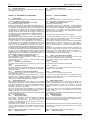
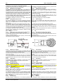
Las bandas para los hombros deben fijarse a un refuerzo
transversal trasero soldado a la estructura de seguridad o fijado a
los puntos de anclaje superiores de las bandas abdominales de
los cinturones.
- El refuerzo transversal será un tubo de, al menos,
38 mm x 2,5 mm o 40 mm x 2 mm de acero al carbono estirado en
frío sin soldadura, con una resistencia mínima a la tracción de
350 N/mm2.
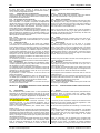
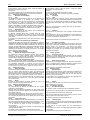
- Se autoriza a fijar las bandas por medio de un lazo o por
tornillos, pero en este último caso debe soldarse una pieza por
cada punto de anclaje (ver dibujo 253-67 para las dimensiones).
Estas piezas se situarán en la barra de refuerzo y las bandas
estarán fijadas a ellas por medio de tornillos M12 8.8 o 7/16 UNF.
These additional devices must be in the locked position while the
vehicle is on the circuit.
Anchorage points on the cab structure must be reinforced to
ensure adequate strength.
The use safety belts in compliance with 8853/98 FIA standard is
compulsory.
The safety belts must comprise at least two shoulder straps and
one lap strap and they must comply with FIA standard n°8854/98
or, preferably, standard n°8853/98.
A safety harness equipped with a turn buckle release system and
having a minimum of five (5) Anchorage points, homologated by
the FIA in accordance with Article 253-6 of appendix J, is
compulsory.
Belts used in circuit competitions must be equipped with a turn
buckle release system. The lap strap must be attached to the cab
by two mounting points. The shoulder straps must be parallel and
must also be attached by two mounting points, situated behind the
seat.
Seat belts which have been involved in a serious accident, or
which are showing signs of wear, should be discarded.
Combinations of parts from different seat belts are not allowed.
Only complete sets, as supplied by the manufacturer, may be
used.
Shoulder straps must be mounted so as to make an angle of not
more than 20° to the horizontal from the wearer's shoulders.
The shoulder straps must be fixed or supported on a rear
transversal tube attached to the safety cage or to the upper
anchorage points of the front belts.
The lap and crotch straps must be fitted in such a way that they
wrap and hold the pelvic region over the greatest possible surface,
the lap straps crossing it below the anterior-superior iliac spines.
Under no conditions must they be worn over the region of the
abdomen.
Care must be taken that the belts cannot be damaged through
chafing against sharp edges.
The shoulder straps must be fixed on a rear transversal tube
welded to the safety cage or attached to the upper anchorage
points of the lap strap belts.
- The transversal reinforcement shall be a tube measuring at least
38 mm x 2.5 mm or 40 mm x 2 mm, made from cold drawn
seamless carbon steel, with a minimum yield strength of 350
N/mm2.
- The straps may be attached by looping or by screws, but in the
latter case an insert must be welded for each mounting point (see
Drawings 253-67 for the dimensions).
These inserts will be positioned in the reinforcement tube and the
straps will be attached to them using bolts of M12 8.8 or 7/16 UNF
specification.
253-67
2.7
Extintores
2.7
Fire extinguishers
El uso de los siguientes productos está prohibido: BCF, NAF.
The use of the following products is prohibited : BCF, NAF.
2.7.1)
Todos los camiones deben estar equipados con uno o 2.7.1)
All trucks must be fitted with one or two fire
dos extintores.
extinguishers.
2.7.2)
Agentes extintores permitidos:
2.7.2)
Permitted extinguishants:
Cualquier AFFF específicamente aprobado por la FIA (ver la Any AFFF which has been specifically approved by the FIA (see
«Lista técnica n.º 6» del Anexo J).
"Technical List n° 6" of the Appendix J).
2.7.3)
Capacidad mínima del extintor:
2.7.3)
Minimum extinguisher capacity:
AFFF:
Las capacidades varían en función del tipo de extintor AFFF:
The capacity may vary according to the type used (see
utilizado (ver la «Lista técnica n.º 6 del Anexo J y considerar la "Technical List n° 6" of the Appendix J and take the same capacity
FIA Sport / Departamento Técnico
FIA Sport / Technical Department
3/21
CMDA / WMSC 03.12.2014
Publicado el / Published on 04.12.2014
Anexo J / Appendix J – Art.290
FIA
misma capacidad indicada para la categoría GT motor).
2.7.4)
Cantidad mínima de agente extintor:
AFFF:
Las cantidades varían en función del tipo de extintor
utilizado (ver la «Lista técnica n.º 6 del Anexo J y considerar la
misma cantidad indicada para la categoría GT motor).
2.7.5)
Todos los extintores deben estar presurizados como se
indica a continuación en función de su contenido:
AFFF:
Las presiones varían según el tipo de extintor utilizado
(ver la «Lista técnica n.º 6» del Anexo J).
Además, en el caso de los AFFF, los extintores deberán estar
equipados con un sistema que permita la verificación de la presión
del contenido.
2.7.6)
La información siguiente deberá figurar visiblemente en
cada extintor:
- capacidad;
- tipo de agente extintor;
- peso o volumen del agente extintor;
- próxima fecha en la que debe revisarse el extintor, que no debe
ser más de dos años después de la fecha de llenado.
2.7.7)
Todos los extintores deben estar protegidos
adecuadamente. Sus fijaciones deben ser capaces de resistir una
deceleración de 25 g. Además, solo se aceptarán las fijaciones
metálicas de desprendimiento rápido con abrazaderas metálicas.
2.7.8)
Los extintores deberán ser fácilmente accesibles para el
piloto.
2.7.9)
Sistemas automáticos:
Se permite, en reemplazo del sistema antes descrito, montar un
sistema extintor automático conforme a las especificaciones del
Artículo 253-7 del Anexo.
2.8
Cortacorrientes general - Interruptor del motor
Los vehículos deben estar equipados con un cortacorrientes y un
dispositivo de corte que apague el motor y desconecte las
baterías de todo circuito eléctrico (excepto el circuito del sistema
de extinción automático). Este interruptor debe estar pintado de
amarillo e identificado por un rayo rojo dentro de un triángulo azul
con borde blanco. Su posición debe estar señalada por
indicaciones bien visibles, situadas a ambos lados del vehículo. El
cortacorrientes y el dispositivo de corte deben estar ubicados en
el exterior de la cabina, entre los largueros del chasis, detrás del
eje trasero. El cortacorrientes debe ser fácilmente accesible en
cualquier momento, incluso si el vehículo está volcado de lado o
sobre el techo.
Además, un interruptor de paro del motor debe situarse en la
cabina, con sus posiciones de encendido-apagado (on-off)
claramente marcadas. Debe poder ser accionado por el piloto
sentado al volante y con el cinturón de seguridad abrochado. El
interruptor debe, asimismo, aislar todas las bombas eléctricas de
combustible.
Nota: En vehículos que usen un interruptor de motor mecánico,
un dispositivo interruptor puede montarse en el exterior, separado
del cortacorrientes eléctrico. No obstante, este dispositivo debe
montarse junto al cortacorrientes, estar claramente identificado y
tener las instrucciones de operación claras (por ejemplo, tirar de la
palanca para detener el motor).
2.9
Estructura de seguridad
2.9.1)
Generalidades:
El interior de la cabina del piloto debe contar con una estructura
de seguridad.
El objetivo principal de dicha estructura de seguridad es proteger
al piloto y al (a los) pasajero(s) en caso de accidente grave.
Las prescripciones mínimas para la estructura de seguridad se
describen en este reglamento; no obstante, a ello hay que añadir
las observaciones siguientes:
Las características principales de una estructura de seguridad
son, ante todo, el resultado de un diseño preciso y detallado, de
una fijación adecuada a la cabina del piloto y de su montaje sólido
y fijo sobre la carrocería.
Se recomienda escoger pies de anclaje que tengan el mayor
diámetro posible a fin de repartir las cargas sobre la máxima
superficie.
Asimismo, se aconseja soldar esta estructura al marco de la
cabina (por ejemplo, a los montantes del parabrisas y de las
puertas) siempre que sea posible.
Esto permite incrementar considerablemente la rigidez y la
estabilidad del dispositivo.
Todas las soldaduras deben ser de la mejor calidad posible y de
penetración completa (preferentemente realizadas mediante
soldadura por arco, especialmente por soldadura en atmósfera de
FIA Sport / Departamento Técnico
FIA Sport / Technical Department
as category GT engine)
2.7.4)
Minimum quantity of extinguishant:
AFFF:
The quantity may vary according to the type used (see
"Technical List n° 6" of the Appendix J and take the same quantity
as category GT engine).
2.7.5)
All extinguishers must be pressurised according to the
contents:
AFFF:
The pressure may vary according to the type used (see
"Technical List n° 6" of the Appendix J).
Furthermore, if filled with an AFFF, each extinguisher must be
equipped with a means of checking the pressure of the contents.
2.7.6)
The following information must be visible on each
extinguisher:
- capacity
- type of extinguishant
- weight or volume of the extinguishant
- date the extinguisher must be checked, which must be no more
than two years after the date of filling.
2.7.7)
All extinguishers must be adequately protected and
must be situated within the survival cell. In all cases their
mountings must be able to withstand a deceleration of 25 g.
Furthermore, only quick-release metal fastenings, with metal
straps, will be accepted.
2.7.8)
The extinguishers must be easily accessible for the
driver.
2.7.9)
Automatic systems:
As an alternative to the above, it is permitted to fit an automatic
extinguishing system complying with Article 253-7 of Appendix J.
2.8
Circuit breaker - Engine shutdown
Vehicles must be fitted with a circuit breaker and a choker device
which shuts down the engine and disconnects the batteries from
all electrical circuitry (except that of the automatic fire extinguisher
system). This switch must be painted yellow and identified by a
red spark on a white-edged, blue triangle. A prominent notice
should be affixed to each side of the vehicle to indicate the
location of the switch. The circuit breaker and the choker device
must be placed on the outside of the cab, between the chassis
side rails, behind the rear axle. The circuit breaker must be easily
accessible at all times, even if the vehicle is lying on its side or
roof.
In addition, an engine shut-down switch must be fitted inside the
cab, with its on-off positions clearly marked. It must be operable by
the driver when normally seated and wearing his seat belt. The
switch must also isolate any electric fuel pumps.
Note : In the case of vehicles which use a mechanical engine
shut-down system, a shut-down device may be fitted on the
outside, separate from the electrical circuit breaker. However, the
device must be fitted close to the circuit breaker, be clearly
marked and have clear operating instructions (e.g. pull knob to
stop engine).
2.9
Safety cage
2.9.1)
General:
The driver's cab must be fitted with an internal safety cage.
The basic purpose of such a safety cage is to protect the driver
and passenger(s) if the vehicle is involved in a serious accident.
The minimum acceptable safety cage requirements are detailed in
these regulations, but the following observations should be noted:
The essential characteristics of a safety cage are first and
foremost the result of a finely detailed construction, suitable
attachment to the cab and snug fitting against the bodywork.
It is recommended that the mounting bases be made as large as
possible in order to spread loads over the maximum area.
It is also advisable to weld the cage to the cab structure (e.g. to
the windscreen and door pillars) wherever possible.
This greatly increases strength and rigidity.
All welding should be of the highest quality possible, with full
penetration (preferably arc welding and in particular under
protecting gas).
4/21
CMDA / WMSC 03.12.2014
Publicado el / Published on 04.12.2014
Anexo J / Appendix J – Art.290
FIA
gas inerte).
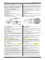
Las prescripciones indicadas son prescripciones mínimas.
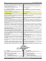
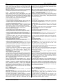
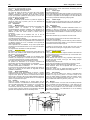
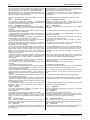
Se permite añadir elementos o refuerzos adicionales (ver el
Anexo J, Artículo 253-8, Dibujos 290-2).
Se prohíbe el cromado de toda o parte de la estructura.
Dentro de la cabina está prohibido llevar los siguientes elementos
entre la estructura del camión y la estructura de seguridad:
* Cables eléctricos
* Conductos que lleven fluidos (excepto el conducto del líquido
limpiaparabrisas)
* Conductos del sistema de extinción
The requirements are a minimum.
It is permitted to fit extra elements or reinforcements in addition to
the basic requirements (See Appendix J Article 253-8 and Drawing
290-2).
The chromium plating of all or part of the cages is forbidden.
Inside the cabin, the passage of the following elements between
the structure of the cabin and the safety cage is forbidden :
*Electric power cables
*Lines carrying fluids (except windscreen washer fluid)
*Lines of the extinguishing system
290-2
2.9.2)
Especificaciones mínimas:
2.9.2)
Minimum specifications:
La forma de la estructura de seguridad mínima permitida se The minimum acceptable safety cage shape is as shown in
presenta en los Dibujos 290-2 del Anexo J, y esto incluye:
Drawing 290-2 of the Appendix J, and this includes:
- Dos barras diagonales de techo.
- Two roof diagonal members
- Dos barras diagonales traseras.
- Two rear diagonal members
- Una barra que una la parte central de la barra superior - One member joining the centre section of the front top cross
transversal delantera a la barra transversal trasera o al montante member to the rear cross member or rear vertical leg.
vertical trasero.
Debe adaptarse lo más fielmente posible a la forma interior de la It must follow the interior shape of the cab as closely as possible,
cabina y no debe presentar irregularidades ni fisuras.
and must be free from unevenness or cracks.
- Dos miembros distintos que unan las barras verticales - Two distinct members joining the front and rear vertical legs, on
delanteras y traseras, en la derecha y en la izquierda:
the right and on the left:
El miembro más bajo estará lo más cerca posible al suelo. The lowest member shall be as close as possible to the floor.
El miembro más alto estará al nivel de la pelvis del conductor.
The highest member shall be at the level of the driver’s pelvis.
Los arcos deben ser fabricados en una sola pieza, todos sus The rollbars must be in one piece, i.e. all the parts must be welded
elementos deben estar soldados entre sí o unidos mediante las together or be connected by the connections defined in Article
conexiones definidas en el Artículo 253-8 del Anexo J.
253-8 of Appendix J.
Si la posición de los pedales se encuentra por delante del eje de If the pedal position is in front of the front wheel centre line, an
las ruedas delanteras, una barra transversal adicional debe unir el additional cross member must join the front outer foot of the front
pie exterior del arco delantero al punto de rotación de la cabina.
rollbar to the cabin pivot point.
El punto de articulación de la cabina y/o el refuerzo original de la The cabin pivot point and/or the original cabin stiffening rail may
cabina puede incorporarse a esta barra.
be incorporated into this member.
Las especificaciones del material deben respetar las The material specification must comply with the one detailed
especificaciones antes detalladas para la estructura de seguridad below for the safety cage and must have a minimum diameter, or
y su diámetro mínimo o longitud de lado debe ser de 25 mm.
side length, of 25 mm.
Nota:
Note :
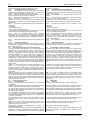
Se permite, e incluso se recomienda, montar barras adicionales It is permissible, and even recommended, to fit additional struts to
en la estructura.
the cage.
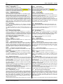
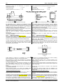
290-2
Estas barras adicionales pueden estar soldadas, atornilladas o
The minimum mounting of the cage to the cab consists of four
fijadas a presión. La estructura debe estar fijada a la cabina mounting bases, one for each vertical leg of the cage. Each
mediante cuatro pies de anclaje como mínimo: uno por cada mounting base must have an area of at least 200 cm2 and a
montante vertical de la estructura. Cada pie de anclaje debe tener thickness of 3 mm.
una superficie mínima de 200 cm2 y un espesor de 3 mm.
Deben fijarse placas de refuerzo con una superficie de, al menos, Reinforcing plates with an area of at least 200 cm 2 and a minimum
200 cm2 y un espesor mínimo de 3 mm de modo tal que el suelo de la thickness of 3 mm must be fitted such that the cab floor is
cabina quede intercalado entre los pies de anclaje y las placas de sandwiched between the mounting bases and the reinforcing
refuerzo. La sujeción de cada pie a su placa de refuerzo debe plates. At least three bolts must clamp each mounting base to its
realizarse mediante, al menos, tres tornillos con especificación mínima reinforcing plate, such bolts to have a minimum specification of 8.8
de 8.8 (grado «S») y un diámetro mínimo de 12 mm. Esta fijación ("S" grade) and a minimum diameter of 12 mm. This mounting
representa el mínimo requerido. Se permite utilizar una mayor represents a minimum. It is permitted to increase the number of
cantidad de tornillos y soldar la estructura a la cabina (por ejemplo, a bolts and to weld the cage to the cab shell (e.g. to the windscreen
los montantes del parabrisas y de las puertas).
and door pillars).
Prescripciones mínimas en cuanto al material de las barras Minimum material specification for all mandatory tubes is as
obligatorias:
follows:
Tubos de acero estirado en frío sin soldaduras, con una Cold drawn seamless steel tube with a minimum tensile strength
FIA Sport / Departamento Técnico
FIA Sport / Technical Department
5/21
CMDA / WMSC 03.12.2014
Publicado el / Published on 04.12.2014
Anexo J / Appendix J – Art.290
FIA
resistencia mínima a la tracción de 340 N/mm2.
Sección mínima admisible para las barras:
57 mm de diámetro exterior x 4,9 mm de espesor de pared
o
63,5 mm de diámetro exterior x 3,2 mm de espesor de pared
o
70 mm de diámetro exterior x 2,4 mm de espesor de pared.
Cada barra del dibujo 290-2 debe estar provista de un orificio de
5 mm de diámetro, bien visible a fin de permitir su control.
Nota: Los tamaños de los tubos anteriormente indicados
constituyen ejemplos de tamaños estándar que deberían estar
fácilmente disponibles. Si, de todos modos, uno de esos tamaños
no puede obtenerse, el tamaño del tubo será aceptable si supera
las dimensiones antes indicadas; por ejemplo, un tubo de
60 mm x 4,9 mm o de 57 mm x 5,0 mm es aceptable en
reemplazo del tamaño especificado de 57 mm x 4,9 mm. No
obstante, cabe destacar que 57 mm constituye el diámetro mínimo
aceptable y que 2,4 mm es el espesor de pared mínimo aceptable
para un diámetro mínimo de 70 mm.
2.9.3)
La estructura de seguridad descrita en los Artículos
2.9.1 y 2.9.2 debe fijarse directamente al chasis mediante piezas
de acero y, como mínimo, en cuatro puntos separados.
Tres de esas conexiones deben cumplir con las especificaciones
de material y de dimensiones del Artículo 2.9.2.
La cuarta conexión debe respetar las mismas especificaciones de
material y tener un diámetro mínimo o longitud de lado de 25 mm.
Dos conexiones deben estar situadas por delante de los pies del
piloto y otras dos por detrás de la posición más retrasada del piloto.
2.10
Protecciones laterales delanteras y traseras
2.10.1)
Protecciones laterales:
Entre las aletas del eje delantero y del eje motor, deben fijarse
protecciones laterales de metal destinadas a evitar la incrustación
de las ruedas y a proteger los depósitos y otros elementos
externos. Las protecciones laterales pueden estar formadas por
los elementos siguientes:
- 1 tubo de acero de 65 mm de diámetro x 3 mm de espesor de
pared mínimo;
o
- 1 tubo de acero de 70 mm de diámetro x 3 mm de espesor de
pared máximo;
o
- 2 tubos de acero de 50 mm de diámetro x 3 mm de espesor de
pared.
Los refuerzos entre el chasis y las protecciones laterales deben
ser de tubo de acero que tenga una resistencia, como mínimo,
igual a la resistencia del material de las protecciones laterales.
Todos los tubos rectangulares deben tener un orificio de 5 mm
perforado en un lugar accesible para el control.
La distancia máxima entre dos refuerzos es de 1,5 m.
La longitud de voladizo de las protecciones laterales no
soportadas debe ser, como máximo, de 500 mm.
El espacio libre máximo autorizado (vista lateral) entre el punto
más cercano de la rueda delantera o trasera y la banda protectora
lateral es de 500 mm.
Los refuerzos deben montarse en el chasis por medio de placas
distribuidoras de carga con una superficie mínima de 100 cm 2 y
un espesor mínimo de 5 mm.
Estas placas deben estar soldadas a los refuerzos y atornilladas
al chasis.
Cada refuerzo debe estar fijado, como mínimo, con 4 tornillos de
8 mm de diámetro. Estos tornillos deben ser, al menos, de clase
8.8 (grado «S»).
Se permite perforar el chasis para la fijación de las protecciones
laterales.
El borde inferior de las protecciones laterales debe estar ubicado
a 500 mm del suelo como mínimo.
El borde superior no puede estar ubicado a más de 1 m del suelo.
Las protecciones deben prolongarse hacia afuera de modo tal que
se encuentren situadas a menos de 300 mm de los extremos del
vehículo visto en planta.
No podrán extenderse más allá de los extremos del vehículo visto
en planta.
Todas las soldaduras deben ser de la mejor calidad con
penetración total.
Debe ser posible inspeccionar todas las juntas de soldadura.
Las protecciones no deben presentar ángulos vivos o aristas en el
vehículo visto en planta.
FIA Sport / Departamento Técnico
FIA Sport / Technical Department
of 340 N/mm2.
Minimum permitted tube cross sections are as follows:
57 mm external diameter x 4.9 mm wall thickness
or
63.5 mm external diameter x 3.2 mm wall thickness
or
70 mm external diameter x 2.4 mm wall thickness.
Each tube in Drawing 290-2 must have an inspection hole of 5 mm
diameter, drilled in an easily visible position.
Note : The tube sizes quoted above are examples of standard
sizes which should be easily available. However, if one of these
sizes cannot be obtained, the tube size will be acceptable if it
exceeds the dimensions shown above, for example 60 mm x
4.9 mm or 57 mm x 5.0 mm is acceptable in place of the specified
57 mm x 4.9 mm. However, it should be noted that 57 mm is the
minimum acceptable diameter, and that 2.4 mm is the minimum
acceptable wall thickness for a minimum diameter of 70 mm.
2.9.3)
The safety cage described in articles 2.9.1 and 2.9.2
must be connected with steel sections to the chassis in a minimum
of 4 separate locations.
Three of these connections must comply with the material and
dimension specifications described in article 2.9.2.
The fourth connection must comply with the same material
specifications and must have a minimum diameter or side length
of 25 mm.
Two connections must be in front of the driver's feet and two
rearward of the rearmost position of the driver.
2.10
Side, front and rear guards
2.10.1)
Side guards:
Metal side guards must be fitted between the wings of the front
and driven axles to prevent wheels interlocking and to protect fuel
tanks and other external parts. The side guards may be made with
any of the following:
- 1 steel tube 65 mm diameter x 3 mm wall thickness minimum;
or
- 1 steel tube 70 mm diameter x 3 mm wall thickness maximum;
or
- 2 steel tubes 50 mm diameter x 3 mm wall thickness.
Outriggers from the chassis to the side guards must be made from
steel tube at least equal in strength to the side guard material.
All tubes must have a 5 mm hole drilled in a visible position for
inspection purposes.
Maximum spacing between any two outriggers is 1.5 m.
Maximum unsupported sideguard overhang is 500 mm.
Maximum permitted gap (in side view) between the front or rear
nearest point of wheel and the sideguard is 500 mm.
Outriggers must be mounted to the chassis using spreader plates
of at least 100 cm² area and 5 mm thickness.
These plates must be welded to the outriggers and bolted to the
chassis.
At least 4 x 8 mm diameter bolts must be used for each outrigger;
these bolts must be at least grade 8.8 ("S" grade).
It is permitted to drill holes in the chassis for the attachment of the
side guards.
The bottom of the side guards must be at least 500 mm above the
ground.
The top must be no more than 1 metre from the ground.
The sideguards must extend outward so that they are within 300
mm of the extremities of the vehicle in plan view.
They may not project beyond the extremities of the vehicle in plan
view.
All welding must be of the highest quality, with full penetration.
It must be possible to inspect all welds.
The side guards must not present any sharp angles or corners on
the vehicle in plan view.
6/21
CMDA / WMSC 03.12.2014
Publicado el / Published on 04.12.2014
Anexo J / Appendix J – Art.290
FIA
Como se describe en el capítulo 6, las protecciones laterales
pueden estar provistas de carenados, pero estos deben poder
desprenderse fácilmente para permitir una cómoda inspección de
las protecciones laterales.
Nota: Este reglamento contiene únicamente las prescripciones
mínimas. Se permite montar protecciones adiciones siempre que
no sobrepasen el perímetro del vehiculo visto en planta.
2.10.2)
Protecciones delanteras y traseras:
Deben montarse protecciones en la parte delantera y en la parte
posterior del vehículo, para impedir que el vehículo pase por encima
de las barreras de seguridad y para facilitar su extracción mediante
camiones equipados con sistemas de elevación hidráulica. Estas
protecciones deben cumplir las prescripciones siguientes:
It is permitted to cover the side guards with fairings as described in
section 6, but all such fairings must be readily detachable to allow
for inspection of the side guards.
Note : This regulation describes the minimum requirements. It is
permitted to fit extra guards if desired, so long as they do not
project beyond the extremities of the vehicle in plan view or extend
forward beyond the perimeter of the vehicle in plan view.
2.10.2)
Front and rear guards:
Guards must be fitted to the front and rear of the vehicle to prevent
it from driving over the top of "armco" safety barriers, and to assist
with "suspended tow" vehicle recovery. These guards must meet
the following requirements:
Protección delantera únicamente:
- La cara frontal de la protección debe ser vertical y debe estar
alineada con la cara frontal del parachoques estándar.
- La parte superior de la protección debe estar alineada con la
parte superior del parachoques estándar.
- La protección delantera debe estar fijada directamente a los
largueros del chasis únicamente, y todas las fijaciones deben
estar situadas por delante de las ruedas delanteras completas.
- En el caso de camiones con capó, se permite el uso de tubo de
acero con un diámetro de 51 mm x 4 mm de espesor.
Protección trasera únicamente:
- La cara posterior de la protección debe ser vertical.
- Ninguna parte de la protección trasera puede estar a más de
200 mm por detrás de los extremos de los largueros del chasis.
- La barra de la parte superior de la protección trasera debe estar,
al menos, al nivel de la parte superior de los rieles del chasis.
- La longitud total de la protección trasera no debe sobrepasar los
2.300 mm.
- La protección trasera debe estar fijada directamente a los
largueros del chasis únicamente, y todas las fijaciones deben
estar situadas por detrás de las ruedas traseras completas.
Protecciones delanteras y traseras:
- La cara inferior de cada protección debe situarse a una distancia
comprendida entre 300 mm y 400 mm por encima del suelo.
- Esa cara inferior debe tener una anchura comprendida entre
1.800 mm y 2.300 mm para cada protección.
- Todas las partes expuestas de las protecciones que no forman
parte del parachoques de origen deben ser fabricadas con tubos.
Front guard only:
- The front face of the guard must be vertical and in line with the
front face of the standard bumper.
- The top face of the guard must be in line with the top face of the
standard bumper.
- The front guard must be attached directly to the chassis rails
only, and all the attachments must be forward of the complete
front wheels.
- In the case of bonnet trucks, these will be permitted to use steel
tube with a diameter of 51 mm x 4 mm wall thickness.
Rear guard only:
- The rear face of the guard must be vertical.
- No part of the rear guard may extend more than 200 mm behind
the end of the chassis rails.
- The top bar of the rear guard must be at least at the level of the
top of the chassis rails.
- The overall width of the rear guard must not exceed 2300 mm.
El material del tubo debe ser de acero y de dimensiones 65 mm x
3 mm mínimo - 70mm x 3mm máximo.
- Los extremos de los tubos no deben formar salientes. Los tubos
inferiores deben estar unidos a los tubos superiores/el
parachoques y no deben presentar bordes o ángulos vivos ni
esquinas salientes.
- Se permite cubrir las protecciones total o parcialmente con
paneles metálicos firmemente sujetos.
- Cada protección debe ser capaz de resistir una carga igual al
peso del vehículo en el eje trasero, aplicada horizontalmente en el
tubo inferior sobre el eje del vehículo. También debe ser capaz de
soportar el peso de la parte trasera del vehículo. Dichas cargas no
deben provocar deformación permanente de estas protecciones.
2.11
Anilla de remolque
Todos los vehículos deben estar equipados con un perno de
remolque desmontable de 14 mm tanto en la parte delantera
como en la parte trasera. La solidez de los pernos debe permitir
remolcar el vehículo en cualquier circunstancia. Deben estar
pintados en un color que contraste (amarillo, rojo o naranja) para
poder identificarlos fácilmente y deben estar disponibles
inmediatamente cuando sea requerido. No deben sobrepasar la
cara delantera del parachoques delantero ni la cara trasera del
parachoques trasero. El perno de remolque debe estar accesible
en todo momento.
2.12
Parabrisas y lunas
2.12.1)
Parabrisas:
Es obligatorio un parabrisas de vidrio laminado, con una marca
que permita verificarlo.
Debe mantenerse, en toda la anchura del parabrisas, una zona
transparente no obstruida de 350 mm de altura como mínimo,
situada directamente al nivel de los ojos del piloto.
Por razones de seguridad, es obligatorio proteger el parabrisas
con una o varias barras para impedir que el parabrisas caiga en la
cabina en caso de accidente. Esas barras deben ser verticales y
estar hechas de metal, y cada una de ellas debe tener una
The tubing material must be steel, dimensions of the tubes 65 mm
x 3 mm minimum – 70mm x 3mm maximum.
- Ends of tubes must not be left exposed. Bottom tubes must be
joined to top tubes/bumper and there must be no sharp edges or
exposed corners or angles.
FIA Sport / Departamento Técnico
FIA Sport / Technical Department
- The rear guard must be attached directly to the chassis rails only
and all the attachments must be rearward of the complete rear
wheels.
Front and rear guards:
- The bottom face of each guard must be between 300 mm and
400 mm above the ground.
- The bottom face of each guard must be between 1800 mm and
2300 mm wide.
- All exposed parts of the guards which are not part of the
standard bumper must be made of tubing.
- It is permitted to cover all or part of the guards with securely
attached metal panels.
- Each guard must be able to withstand a load equal to the vehicle
weight on the rear axle, applied horizontally to the bottom tube,
along the axis of the vehicle. It must also be capable of supporting
the weight of the rear end of the vehicle. These loads must not
cause permanent distortion of the guards.
2.11
Towing eye
All vehicles must be fitted with a 14 mm removable towing pin at
both front and rear. The strength of these 14 mm pins must be
sufficient to allow the vehicle to be towed under all circumstances.
They must be painted in a contrasting colour (yellow, red or
orange) for easy identification and be available for immediate use
when required. They must not project beyond the front face of the
front bumper or the rear face of the rear bumper. The towing pin
must be accessible at all times.
2.12
Windscreen and windows
2.12.1)
Windscreen:
A windscreen of laminated glass must be fitted, bearing a mark to
verify the fact.
A transparent and unobstructed area of minimum 350 mm in
height, covering the entire width of the windscreen, must be
located directly opposite the driver’s eyes.
For safety reasons, it is mandatory for the windscreen to be
backed by one or more bars to prevent it from collapsing into the
cabin during an accident. Each bar must be vertical, made of
metal and have a section of 45 mm2 minimum.
7/21
CMDA / WMSC 03.12.2014
Publicado el / Published on 04.12.2014
Anexo J / Appendix J – Art.290
FIA
sección de 45 mm2 como mínimo.
2.12.2)
Luna trasera:
Las láminas plateadas están prohibidas.
Puede ser de plástico transparente con espesor mínimo de 4,8 mm.
Si la luna trasera es de vidrio de seguridad, es obligatorio que sea
recubierta con una película plástica autoadhesiva para evitar las
lesiones que podría ocasionar el vidrio roto.
2.12.3)
Ventanillas laterales:
Las láminas tintadas están prohibidas.
Debe ser de plástico transparente de 4,8 mm de espesor mínimo.
Debe montarse una red de protección que cubra toda el área de
abertura de la ventanilla en el interior de ambas puertas.
Esta red no debe obstaculizar la visión, pero sí debe impedir que
los brazos del piloto salgan por la ventanilla si el vehículo vuelca.
La red de protección debe estar asegurada en la parte superior de
la puerta y tener dos hebillas de liberación rápida en la parte
inferior de la red y poder quitarse desde el interior o desde el
exterior de la cabina. El Delegado Técnico debe aprobar todas las
redes de protección.
2.13
Retrovisores
El camión debe estar equipado con dos espejos retrovisores
exteriores, uno a cada lado del camión, que permitan una visión
eficaz hacia atrás.
La superficie reflectante de cada retrovisor debe tener una
dimensión mínima de 100 x 150 mm y un área mínima de 150
cm2.
Es obligatoria una cámara retrovisora.
2.14
Protección contra incendios
Todos los vehículos deben estar equipados con un panel de
protección fabricado con un material no inflamable y ubicado entre
el motor/la transmisión y el compartimento del piloto, que impida
la penetración de fluidos o llamas en caso de incendio. Todos los
orificios deben estar sellados con fibra de vidrio.
Se prohíbe el uso de magnesio para los paneles de separación.
2.15
Ruedas y neumáticos
2.15.1)
Llantas:
Las llantas partidas están prohibidas.
Se permiten las llantas de aluminio forjado en el exterior del eje
trasero.
2.15.2)
Tapas para tuercas de ruedas:
Deben montarse firmemente tapas para tuercas de ruedas en
todas las ruedas del eje de dirección cuyas tuercas formen
salientes o tengan ángulos vivos. Ninguna parte de las tuercas o
de los bulones de las ruedas podrá sobresalir de estas tapas. Las
tapas deben fijarse a la llanta por cuatro puntos de anclaje como
mínimo.
2.15.3)
Contrapesos de equilibrado de ruedas:
Está prohibido utilizar contrapesos de equilibrado desmontables
en las ruedas.
Los contrapesos deben estar soldados o atornillados a la llanta.
2.15.4)
Neumáticos:
No se admitirá ningún neumático que los comisarios consideren
no conforme o peligroso por una u otra razón. Ningún vehículo
equipado con tales neumáticos será admitido en la pista.
2.16
Árboles de transmisión
Deberá protegerse, como mínimo, el 50% de la longitud del árbol
de transmisión, a lo largo de toda su circunferencia, por medio de
acero de un espesor mínimo de 6 mm, para que no toque el suelo
en caso de ruptura.
Esta carcasa puede estar partida a lo largo de su longitud y las
dos partes unidas por al menos 6 tornillos de M10 de calidad
mínima 8.8 (grado S).
Debe tener 4 puntos de fijación (2 atornillados a los largueros del
chasis principal y 2 atornillados al sub chasis autorizado) y no se
contarán como miembros transversales.
Los cuatro tornillos usados para fijar esta carcasa deben ser, al
menos, de M12 y de calidad mínima 8.8 (grado S).
Los árboles de transmisión no deben atravesar un depósito de
combustible, agua o aire.
2.17
Luces traseras y de freno
Una luz roja de, al menos, 20 W (máximo: 30 W) dirigida hacia
atrás debe montarse en el plano trasero de la cabina del vehículo.
Esta luz debe estar ubicada tan alto como sea posible en el centro
del vehículo. Debe estar encendida durante todo el tiempo que
duren las tandas de entrenamiento y las competencias. La
superficie luminosa de esa luz no debe exceder los 100 cm2 y
debe ser superior a 60 cm2.
La potencia de las luces traseras de frenos debe ser de, al menos,
FIA Sport / Departamento Técnico
FIA Sport / Technical Department
2.12.2)
Rear window:
Silvered films are not permitted.
It may be in transparent plastic of 4.8 mm minimum thickness.
If the rear window is made of safety glass, it is mandatory that it is
covered with self-adhesive plastic film in order to prevent possible
injury from broken glass.
2.12.3)
Side windows:
Tinted films are not permitted.
It may be in transparent plastic of 4.8 minimum thickness.
A protective net covering all the area of the window aperture must
be fitted to the inside of both doors.
It must not impede vision, but must be able to prevent the driver's
arms from falling out of the windows if the vehicle rolls over.
The protective net must be secured at the top of the door and
have two quick release buckles fitted at the bottom of the net and
be removable from inside or outside the cabin. The Technical
Delegate must approve all protective nets.
2.13
Rear view mirrors
The truck must be fitted with two external rear view mirrors, one
fitted on each side of the truck, in order to give an efficient view to
the rear.
Each one must have a reflective surface of 100x150 mm minimum
dimensions and a minimum area of 150 cm 2.
A rear view camera is mandatory.
2.14
Fire protection
All vehicles must have a protective bulkhead of non-flammable
material between the engine/transmission and the driver's
compartment, capable of preventing the passage of fluid or flames
in the event of fire. All gaps must be sealed with glass fibre.
It is forbidden to use magnesium for the bulkheads.
2.15
Wheels and tyres
2.15.1)
Wheel rims:
Split rim wheels are forbidden.
Aluminium forged rims are allowed at the outside of the rear axle.
2.15.2)
Wheel nut covers:
Wheel nut covers must be firmly affixed to all wheels on steering
axles which have protruding nuts with sharp corners. No part of
the wheel nuts or studs may project through these covers, which
must be fixed to the rims by means of at least 4 separate
attachments.
2.15.3)
Wheel balance weights:
It is prohibited to have removable balance weights fitted on any
wheel.
Balance weights must be welded or screwed onto the rim.
2.15.4)
Tyres:
Any tyre which the scrutineers consider to be dangerous or in
breach of the regulations, for one reason or another, will be
rejected. Any vehicle fitted with such a tyre will not be allowed on
the circuit.
2.16
Propeller shafts
A minimum of 50% of the propeller shaft length must be covered
all around its circumference by a steel material with a minimum
thickness of 6 mm, so as to prevent it from hitting the ground in
case of breakage.
This cover may be split along its length and the two part joined
together by means of at least 6 M10 bolts to have a minimum
specification of 8.8 (S grade).
It must have 4 fixing points (2 bolted to the main chassis rails and
2 bolted to the authorised under frame) and will not be counted as
a transverse member.
The 4 bolts used to fix this cover must be at least M12 bolts to
have a minimum specification of 8.8 (S grade).
Propeller shafts must not pass through a fuel, water or air tank.
2.17
Rear warning light and braking lights
A rearward facing red light of at least 20 watts (maximum 30
watts) must be mounted on the rear panel of the cab. It must be
situated as high as possible on the vehicle centreline. It must be
switched on throughout all practice sessions and races. The
lighted area of this lamp must not exceed 100 cm 2 but must be
greater than 60 cm2.
The power of the braking lights must be at least 20W (maximum
8/21
CMDA / WMSC 03.12.2014
Publicado el / Published on 04.12.2014
Anexo J / Appendix J – Art.290
FIA
20 W (máximo: 30 W).
Además del dispositivo estándar, es obligatorio instalar 2 luces de
freno (en funcionamiento durante la carrera) en la parte de atrás
de la cabina, a la altura de la luz roja antes mencionada.
También
puede
utilizarse
un
sistema
con
diodos
electroluminiscentes, a condición de que provenga de un vehículo
comercializado.
La cantidad de diodos electroluminiscentes debe estar
comprendida entre 25 y 100, y cada uno de ellos debe tener un
diámetro mínimo de 8 mm.
Las luces de freno deben ser visibles desde una posición situada
a tres metros de la parte trasera del camión y a dos metros
verticalmente.
2.18
Cabina
2.18.1)
Construcción:
La cabina debe conservar su resistencia y su integridad originales.
Cualquier corrosión de la estructura de la cabina o de los
montantes supondrá que el vehículo sea rechazado en las
verificaciones técnicas.
2.18.2)
Bloqueo de las puertas:
Las puertas deben estar destrabadas cuando el vehículo se
encuentra en la pista. Las manillas de las puertas deben poder
accionarse desde el interior y desde el exterior del vehículo.
2.18.3)
Herramientas:
Todas las herramientas y demás equipos que no estén fijos deben
quitarse.
2.18.4)
Asientos:
Todos los asientos de los ocupantes deben ser homologados por
la FIA (norma 8855-1999 o 8862/2009) con extensión para
guarnecido de material absorbente de energía y no inflamable
alrededor de la cabeza del piloto, y no deben haber sufrido
modificaciones.
Ver Artículo 253-16.6).
Si hay un cojín entre el asiento homologado y el ocupante, su
máximo espesor debe ser de 50 mm.
Todos los asientos montados en el vehículo deben estar
sólidamente fijados y no debe ser posible inclinarlos o hacerlos
girar ni rebatirlos.
El asiento del piloto debe sostenerlo y mantenerlo en su lugar en
la cabina.
Todos los asientos deben estar girados hacia adelante.
Todos los asientos de pasajeros pueden quitarse.
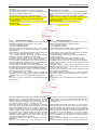
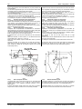
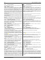
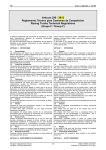
Todas las juntas con tornillos entre el (los) asiento(s) y la cabina
(es decir, las juntas entre asiento y bastidor auxiliar [si lo hay] y
entre bastidor auxiliar y suelo) deben realizarse con contraplacas
y, como mínimo, con 4 tornillos de, al menos, 8 mm de diámetro o
con 6 tornillos de 6 mm de diámetro, de clase 8.8 (grado «S»)
como mínimo.
El área de contacto mínima entre el soporte, la cabina y la
contraplaca es 40 cm2 por cada fijación (véase el Anexo J, dibujo
253-65).
Las correderas de los asientos deben bloquearse y fijarse
mediante un sistema que requiera el uso de herramientas.
30W).
In addition to the standard system, it is compulsory to install 2
brake lights (in working order during the race) on the back of the
cab, at the height of the red light mentioned above.
A LED unit may also be used provided it is from a commercial
vehicle.
The number of LEDs must be from 25 to 100 with a minimum
diameter of 8 mm each.
The braking lights must be visible from a position 3 metres to the
rear of the truck and 2 metres vertically.
2.18
Cab
2.18.1)
Construction:
The cab must retain its original strength and integrity. Any
corrosion of the cab structure or mountings will cause the vehicle
to be rejected at scrutineering.
2.18.2)
Door locks:
Door locks must be kept in the unlocked position while the vehicle
is on the circuit. Door catches must be fully operable from both
inside and outside the vehicle.
2.18.3)
Tools:
All tools and other loose equipment must be removed.
2.18.4)
Seats:
All the occupants' seat must be homologated by the FIA (88551999 or 8862/2009 standards), with an extension padded with
energy-absorbing and non-inflammable material around the
driver's head, and must not be modified.
See Article 253-16.6).
If there is a cushion between the homologated seat and the
occupant, the maximum thickness of this cushion is 50 mm.
All seats fitted must be firmly attached and must not slide, tilt,
hinge or fold.
The driver's seat must support the driver and hold him in position
inside the cab.
All seats must face forward.
Passenger seats may be removed.
All joints between any seat and the cab (i.e. seat to subframe (if
fitted) and subframe to floor) must have at least 4 x 8 mm diameter
or 6 x 6 mm diameter bolts, minimum grade 8.8 ("S" grade), with
counterplates.
The minimum area of contact between support, cab and
counterplates is 40 cm² for each mounting point (See Appendix J
Drawing 253-65).
Sliding seat runners must be locked and bolted in position by a
system requiring the use of tools.
253-65
2.18.5)
Bloqueo de la dirección y mecanismo de retirada 2.18.5)
Steering lock and quick release mechanism:
rápida:
2.18.5.1
Debe quitarse cualquier dispositivo de bloqueo de la 2.18.5.1
Any steering lock system fitted to the vehicle must be
dirección que se encuentre montado en el vehículo.
removed.
2.18.5.2
El volante debe estar equipado con un mecanismo de 2.18.5.2
The steering wheel must be fitted with quick release
retirada rápida. Debe consistir en un collarín concéntrico al eje del mechanism. It must consist of a flange concentric to the steering
volante, coloreado amarillo por medio de anodización o cualquier wheel axis, coloured yellow through anodisation or any other
otro revestimiento duradero, e instalado en la columna de durable yellow coating, and installed on the steering column
dirección por detrás del volante.
behind the steering wheel.
El sistema de desbloqueo debe ser operado tirando del collarín The release must be operated by pulling the flange along the
siguiendo el eje de la dirección.
steering wheel axis.
2.18.5.3
Si la columna de dirección pasa entre las piernas del 2.18.5.3
If the steering column passes in between the driver’s
piloto, debe estar recubierta por una protección desmontable de legs, it must be covered with protective detachable foam in order
espuma que permita evitar lesiones en las rodillas.
to prevent injures to the driver’s knees.
2.18.6)
Freno de estacionamiento:
2.18.6)
Parking brake:
El mando del freno de estacionamiento debe poder identificarse The location of the parking brake control must be clearly indicated
fácilmente mediante una indicación ubicada dentro de la cabina. by a notice placed inside the cab. The parking brake control must
FIA Sport / Departamento Técnico
FIA Sport / Technical Department
9/21
CMDA / WMSC 03.12.2014
Publicado el / Published on 04.12.2014
Anexo J / Appendix J – Art.290
FIA
El piloto debe poder accionar el mando del freno de
estacionamiento mientras se encuentra normalmente sentado y
con su cinturón de seguridad abrochado.
2.18.7)
Limpiaparabrisas y lavaparabrisas:
Todos los vehículos deben estar equipados con limpiaparabrisas y
lavaparabrisas. Dichos dispositivos deben estar en condiciones de
funcionamiento en todo momento.
2.19
Recuperador de aceite del motor
Todos los respiraderos del motor con salida al aire libre deben
estar conectados a un depósito recuperador estratégicamente
ubicado para evitar que el aceite se derrame sobre la pista. Si se
utiliza un solo depósito, debe tener una capacidad mínima de
4 litros. Es posible utilizar varios depósitos; en ese caso, cada uno
de ellos debe tener una capacidad mínima de 2 litros.
Los depósitos pueden estar fabricados de cualquier material, pero
debe ser posible ver el contenido del depósito (por ejemplo, una
parte transparente es obligatoria en un depósito metálico y los
depósitos de plástico deben ser traslúcidos). Todos los depósitos
deben poder ser vaciados fácilmente.
2.20
Faros
Todos los faros delanteros con una superficie superior a 32 cm²
deben estar protegidos de manera adecuada por si se produce
una rotura del vidrio.
2.21
Tuberías de escape
A fin de minimizar el riesgo de que piezas muy calientes
provenientes de un motor/turbocompresor roto se esparzan sobre
la pista, debe montarse un dispositivo protector en el extremo de
todos los tubos de escape. Este dispositivo debe estar realizado
de modo tal que una pieza con un diámetro superior a los 40 mm
no pueda pasar directamente por el tubo de escape. Un ejemplo
de dispositivo protector conveniente: láminas de metal de 1,6 mm
de espesor x 25 mm de anchura, soldadas a la salida del escape,
separadas en sus tramos orientados en el sentido del flujo por una
distancia inferior a 40 mm.
Los vehículos que utilizan un filtro de humos en el extremo del
tubo de escape no necesitan la protección anteriormente descrita.
2.22
Guardabarros
Todas las ruedas deben estar equipadas con guardabarros. Estos
no deben presentar ángulos vivos y deben cubrir la anchura total
del neumático en un arco ininterrumpido de 120°.
Los guardabarros deben sobrepasar, hacia adelante, el centro del
eje correspondiente en proyección vertical. El extremo trasero del
guardabarros no debe encontrarse a más de 75 mm por encima
del centro del eje correspondiente.
El guardabarros no debe encontrarse a más de 200 mm del
exterior del neumático.
El borde posterior del guardabarros trasero se debe instalar con
una faldilla que se extenderá, al menos, 4 cm por detrás de las
ruedas traseras y medirá no menos de 200 mm desde el suelo.
2.23
Señal sonora de marcha atrás
Los vehículos deben estar equipados con una señal sonora que
suene al poner la marcha atrás.
be operable by the driver while normally seated and with the seat
belt fastened.
ARTÍCULO 3: REGLAMENTO ESPECÍFICO PARA CAMIONES
DE CARRERA
ARTICLE 3:
3.1
Generalidades
Toda modificación está prohibida salvo si está expresamente
autorizada por el reglamento específico del grupo en el que el
camión está inscrito o por las siguientes prescripciones generales,
o impuesta por el capítulo «Equipamiento de Seguridad». Los
componentes del camión deben mantener su función de origen y
estar habilitados para su función.
Es responsabilidad de cada concursante demostrar a los
Comisarios Técnicos y a los Comisarios Deportivos que su
camión cumple con los reglamentos en su totalidad, en cualquier
momento de la competición.
Todos los vehículos presentados para examen deben estar
limpios y secos.
A menos que el presente reglamento las prohíba específicamente,
se permite utilizar piezas de igual especificación para reemplazar
directamente las piezas del fabricante, a condición de que dichas
piezas estén disponibles en el comercio como piezas de recambio
directo y que tengan el mismo diseño que las piezas provenientes
del fabricante del vehículo.
La reparación de componentes puede efectuarse por los métodos
aceptados, tales como la soldadura. Los concursantes deben
tener en cuenta las limitaciones de tal acción: la adición de
cartelas, de soldadura o de material, el cambio de forma, de
3.1
General
All modifications are forbidden unless expressly authorised by the
regulations below or imposed under the chapter "Safety
Equipment". The components of the truck must retain their original
function and be fit for porpuse.
FIA Sport / Departamento Técnico
FIA Sport / Technical Department
2.18.7)
Windscreen wipers and washers:
All vehicles must be fitted with windscreen wipers and washers.
These must be maintained in working order at all times.
2.19
Engine - Oil catchtank
All engine breathers venting to atmosphere must lead into a catch
tank, arranged in such a way as to prevent oil from spilling onto
the track. If a single catch tank is used, it must have a capacity of
at least four litres. It is permitted to use multiple tanks, but each
tank must be able to hold at least 2 litres.
Tanks may be made of any material, but it must be possible to
view the contents of the tank (e.g. a sight glass is required in a
metal tank, and plastic tanks must be translucent). All tanks must
be capable of being easily emptied.
2.20
Lamps
All forward facing lamps with a surface area of more than 32 cm2
must be adequately protected and secured in case of glass
breakage.
2.21
Exhaust pipes
In order to minimise the risk of hot parts of a broken
engine/turbocharger being blown onto the circuit, a protection
device must be fitted to the end of all exhaust pipes. This device
must be made so that any part with a diameter of more than 40mm
cannot pass directly out of the exhaust pipe. An example of a
suitable protection device is : strips of metal, 1.6 mm thick x 25mm
wide, welded into the end of the exhaust, edge-on to the exhaust
gas flow, at less than 40 mm spacing.
Vehicles using a smoke filter at the end of the exhaust pipe do not
need the protection described above.
2.22
Mudguards
All wheels must be equipped with mudguards. They must have no
sharp edges and must cover the full width of the tyre over a
continuous arc of 120°.
The mudguards must extend forward of the relevant axle centre
line in vertical projection. The trailing edge of the mudguard must
be no more than 75 mm above the relevant axle centreline.
The mudguard must be situated not more than 200 mm from the
outside of the tyre.
The trailing edge of the rear mudguards must be fitted with a mud
flap which shall extend at least 4 cm outside both rear tyres and
measure no less than 200 mm from the ground.
2.23
Audible reversing warning
Vehicles must be fitted with an audible warning that sounds when
the reverse gear is engaged.
SPECIFIC REGULATIONS FOR RACE TRUCKS
It is the duty of each competitor to satisfy the Scrutineers and the
Stewards that his truck complies with these regulations in their
entirety at all times during the competition.
All vehicles must be presented at scrutineering in a clean and dry
condition.
Unless specifically prohibited by these regulations, it is permitted
to use "pattern parts" as direct replacement of manufacturer's
parts, provided such parts are commercially available as direct
replacements and are of the same design as the vehicle
manufacturer's parts.
Repair of components may be effected using accepted repair
methods such as welding. Competitors' attention is drawn to the
limitations of such action : the addition of gussetts, additional
welding or material, the change of shape, design, material, surface
10/21
CMDA / WMSC 03.12.2014
Publicado el / Published on 04.12.2014
Anexo J / Appendix J – Art.290
FIA
diseño, de material o de acabado superficial, o la retirada de
material constituyen una «modificación».
Toda referencia a una especificación y/o a piezas y/o materiales
estándar en el presente reglamento será interpretada como una
referencia a los elementos estándar mencionados por el
fabricante, únicamente tal como se mencionan en la definición del
tipo apropiado. No abarcará las opciones del fabricante.
Los componentes deben permanecer de origen, salvo si los
artículos siguientes permiten modificaciones.
Los componentes mecánicos siguientes deben provenir de un
tractocamión homologado para el transporte de mercancías:
- Caja de cambios
- Ejes delantero y trasero
- Caja de dirección
- Componentes del sistema de frenado
Ningún elemento mecánico debe estar diseñado para generar
efectos aerodinámicos.
Fuera del sistema de gestión del motor, los sistemas de bucles
cerrados están prohibidos.
3.2
Dimensiones (véase el dibujo 290-3)
finish or removal of material constitute a "modification".
Any reference to standard specification and/or parts and/or
materials in these regulations shall be interpreted as a reference
to the manufacturer's listed standard item(s) only as set down in
the appropriate type approval. It shall not include manufacturer's
options.
The components must remain original unless modifications are
permitted by the following articles.
The following mechanical components must be from road-going
tractors homologated for the transportation of merchandise:
- Gearbox,
- Front and rear axles,
- Steering box,
- Components of braking systems.
No mechanical part must be designed to generate an aerodynamic
effect.
Apart from the engine management systems, closed loop systems
are prohibited.
3.2
Dimensions (See Drawing 290-3)
290-3
3.2.1)
Anchura total:
3.2.1)
Overall width:
La anchura total del vehículo está limitada a 2.550 mm The overall width of the vehicle is limited to 2550 mm excluding
excluyendo los espejos retrovisores.
rear view mirrors.
3.2.2)
Altura:
3.2.2)
Height:
La altura del vehículo en el punto más elevado de la cabina no The height of the vehicle at the highest point of the cab must not
debe ser inferior a 2.500 mm medidos verticalmente sobre una be less than 2500 mm measured vertically over a width of
anchura de 1.800 mm.
1800 mm.
Esta medición debe efectuarse 200 mm por delante de la parte This measurement must be taken 200 mm in front of the rearmost
más retrasada de la cabina.
point of the cab.
3.2.3)
Distancia al suelo:
3.2.3)
Ground clearance:
La distancia al suelo mínima es de 200 mm, a excepción de los The minimum ground clearance is 200 mm except for the front and
carenados de carrocería delanteros y laterales definidos en el side bodywork fairings defined in article 3.18.3 which have a
Artículo 3.18.3, que deben respetar una distancia al suelo mínima minimum ground clearance of 100 mm.
de 100 mm.
Las protecciones y parachoques deben respetar la distancia al The guards and bumper must respect the 200 mm minimum
suelo mínima de 200 mm, excepto para el cárter del eje trasero, ground clearance, except for the housing of the rear axle where
cuya distancia al suelo debe ser, como mínimo, de 170 mm.
the minimum ground clearance must be 170 mm.
3.3
Peso
3.3
Weight
El peso mínimo permitido para los camiones de carrera está The minimum allowed weight for Race Trucks is defined as
definido como se indica a continuación:
follows:
- 5.400 kg, de los cuales 3.200 kg en la parte delantera
- 5400 kg, of which 3200 kg measured at the front wheels
Se permite completar el peso del vehículo mediante uno o varios It is permitted to make up the weight of the vehicle with one or
lastres, a condición de que se trate de bloques sólidos y unitarios, several ballasts, provided that they are strong and unitary blocks,
fijados por medio de herramientas, fáciles de precintar, ubicados attached by means of tools, easily accessible for affixing seals,
entre los largueros del chasis.
placed between the chassis rails.
3.4
Chasis
3.4
Chassis
3.4.1)
Generalidades:
3.4.1)
General:
Todos los componentes del chasis deben ser de aleación de All chassis components must be made of iron-based alloys.
hierro.
Se permite modificar parcialmente el bastidor del chasis:
It is permitted to locally modify the chassis frame:
- a fin de cumplir con los requisitos de seguridad especificados en - in order to comply with the safety requirements specified within
el presente reglamento,
these regulations.
- para fijar los refuerzos permitidos descritos en el Artículo 3.4.2.
- in order to fit the authorised reinforcements described in
Article 3.4.2.
A excepción de las protecciones delanteras y traseras With the exception of the front and rear guards (Art. 2.10.2), all
(Art. 2.10.2), todas las modificaciones deben quedar:
modifications must remain:
- entre la parte delantera de las ruedas delanteras completas y la - between the front of the complete front wheels and the rear of
parte posterior de las ruedas traseras completas (dibujo 290-3);
the complete rear wheels (Drawing 290-3);
- entre los planos verticales y longitudinales situados a 120 mm de - between two vertical and longitudinal planes situated 120 mm
las superficies exteriores de los largueros (dibujo 290-4).
from the outer surfaces of the chassis rails (Drawing 290-4).
Los soportes del motor y de la transmisión deben estar fijados Engine and transmission supports must be fixed directly to the
directamente a los largueros o un travesaño que debe fijarse en el chassis rails or to a tranversal reinforcement that must be fixed
interior del chasis de conformidad con el Artículo 290-3.4.2.
within the chassis in compliance with Article 290-3.4.2.
Los largueros del chasis deben tener una sección en «U» (véase The chassis rails must have a "U" shaped section (see Drawing
el dibujo 290-5).
290-5).
Con el fin de permitir algunas variaciones respecto a la In order to allow for some variations from the original construction
FIA Sport / Departamento Técnico
FIA Sport / Technical Department
11/21
CMDA / WMSC 03.12.2014
Publicado el / Published on 04.12.2014
Anexo J / Appendix J – Art.290
FIA
construcción original de los fabricantes, se aplicarán las
siguientes tolerancias:
-Distancia entre ejes:
+ / - 50 mm
-Anchura del chasis:
+ / - 1%
-Altura y el espesor de los carriles U: + / - 1%
290-3
No se permite soldar ningún elemento a esas vigas.
Es indispensable que se respeten las dimensiones mínimas
definidas en el dibujo 290-5 entre las líneas centrales de los ejes
delantero y trasero. Se admitirá una tolerancia de -1500 mm en la
longitud del chasis entre los ejes delantero y trasero donde se
requiere la viga en «U» descrita en el dibujo 290-5.
Las vigas no deberán modificarse ni recortarse en ningún punto y
deberán tener la forma de una «U» simétrica.
Simplemente podrán perforarse para fijar en ellas las diferentes
piezas así como los refuerzos y soportes descritos en el
Artículo 3.4.2.
Las opciones del fabricante relativas a la forma y al material del
chasis están prohibidas.
3.4.2)
Refuerzos permitidos:
Todos los refuerzos deben ser de aleación de hierro.
Se permite unir los largueros mediante travesaños de secciones
constantes cuyas dimensiones no deben exceder la altura de los
largueros medidos en el lugar de los refuerzos (dibujo 290-6).
La placa de fijación debe tener la forma de un cuadrado cuya
dimensión máxima del lado no debe exceder la altura del chasis
en ese lugar. Los tornillos de fijación deben estar colocados
directamente sobre el travesaño.
by the manufacturers the following tolerances will be applied :
- Wheelbase:
- Chassis width:
-Height and thickness of U rails:
+/- 50mm
+/- 1 %
+/- 1 %
2
90-4
290-5
It is not be permitted to weld anything whatsoever to these chassis
rails.
It is essential that the minimum dimensions set out in Drawing
290-5 are respected between the centrelines of the front and rear
axles. A tolerance of -1500mm will be applied to the length of
chassis between the front and rear axles requiring a 'U' section of
the dimensions shown in Drawing 290-5.
The chassis rails must not be modified or cut at any point and
must form a symmetrical "U" shape.
They may only be pierced so that various parts , as well as the
reinforcements and supports described in article 3.4.2, may be
affixed.
Manufacturer's options on chassis shape and material are
prohibited.
3.4.2)
Authorised reinforcements:
All reinforcements must be made of iron-based alloys.
Chassis rails may be joined together by transversal members with
a constant section the dimensions of which must not exceed the
height of the main members measured at the location of the
reinforcement (Drawing 290-6).
The fixing plate to which the additional reinforcement is attached
must be square in shape and must not exceed the height of the
chassis rail at the fixing point. The fixing nuts must be bolted
directly to the cross member.
290-6
Puede utilizarse un máximo de 16 travesaños, sin contar las A maximum of 16 transversal members may be used, excluding
fijaciones del radiador, del motor y de la caja de cambios.
for radiator, engine and gearbox mountings.
Estos travesaños se contarán de conformidad con la definición These transversal members will be counted according to the
incluida en el Artículo 290-1.8, desde el extremo delantero hasta definition given in Article 290-1.8, from the front end to the rear
el extremo posterior del chasis.
end of the chassis.
Las únicas excepciones a esta definición de travesaño son las The only exceptions to this definition of transversal members are a
vigas transversales simples que sirven de soporte a los single transversal member as front and rear bumper support and
parachoques delantero y trasero así como los ejes delantero y front and rear axles.
trasero.
El depósito de combustible debe estar fijado con un mínimo de The fuel tank must be fixed to a minimum of two transversal
dos travesaños solamente.
members only.
Ningún travesaño situado en el interior de la batalla puede No transversal member situated within the wheelbase may
sobresalir de la superficie superior de los largueros del chasis.
protrude beyond the upper surface of the main members of the
chassis frame.
- Refuerzos adicionales (dibujo 290-7):
- Additional reinforcements (Drawing 290-7):
Puede utilizarse una cantidad máxima de cinco placas por A maximum of 5 fixing plates per chassis rail may be used to
larguero para fijar los travesaños unidos a los largueros.
connect the transversal members that are joined with longitudinal
members.
La longitud y anchura de las placas de fijación del bastidor auxiliar The length and width of each of the fixing plates of the underframe
no debe superar, en ningún lugar de la zona de fijación, la altura must not exceed the maximum height of the main chassis rails at
de los largueros. Cada placa de fijación puede utilizar un máximo any point of the fixation zone. Each fixing plate may use a
de seis pernos cuyo diámetro no debe ser superior a los 14 mm.
maximum of 6 bolts of a diameter no greater than 14 mm.
Los puntos de fijación deben situarse en la batalla del camión, The fixations points must be situated within the wheelbase,
FIA Sport / Departamento Técnico
FIA Sport / Technical Department
12/21
CMDA / WMSC 03.12.2014
Publicado el / Published on 04.12.2014
Anexo J / Appendix J – Art.290
FIA
entre la parte anterior de la rueda delantera y la parte posterior de
la rueda trasera.
Los refuerzos longitudinales que unen los travesaños deben estar
conectados a las cinco placas antes mencionadas.
La cantidad de refuerzos longitudinales no debe superar los 18 en
una vista lateral del camión.
Todos esos refuerzos deben situarse bajo los largueros del chasis
y deben tener una circunferencia máxima de 280 mm.
Una sección en «U» o en «L» será considerada como equivalente
a un rectángulo completo a los efectos de esta medición.
3.4.3)
Soportes adicionales para equipamiento:
Se permiten soportes adicionales para equipamiento.
Deben estar atornillados a los largueros por medio de dos placas,
como máximo, cuya longitud no debe superar los 250 mm. La
distancia entre estas placas debe ser superior a 300 mm.
Ningún depósito de agua debe estar situado dentro de la batalla y
entre los dos largueros del chasis.
3.4.4)
Quinta rueda (véase el dibujo 290-8):
Cualquiera sea la especificación del fabricante, la articulación
para acoplamiento del semirremolque («quinta rueda») debe estar
ubicada por delante de la línea central del eje motor.
La quinta rueda debe respetar las dimensiones del dibujo 290-8 y
tener un espesor de 30 mm visto desde el lateral.
El material es libre, pero la quinta rueda debe ser de construcción
rígida.
Debe estar situada, en todo momento, a una distancia del suelo
comprendida entre 1.000 mm y 1.300 mm.
Para tomar esta medida, la quinta rueda debe estar en posición
horizontal.
Ninguna otra parte, en un círculo con un radio de 2.040 mm y
cuyo centro sea el eje de articulación de la quinta rueda, podrá
estar situada por debajo de la superficie superior de la quinta
rueda (dibujo 290-3).
between the front of the front wheel and the rear of the rear wheel.
290-3
3.4.5)
Placa de fijación del lastre
Una placa plana, que no mida más de 500 mm en el sentido de la
longitud de los largueros y con no más de 6 mm de espesor,
pueden fijarse a los refuerzos permitidos (Artículo 3.4.2 y
dibujo 290-7).
El lastre desmontable puede fijarse sobre esa placa a condición
de que esta no esté en contacto con los refuerzos permitidos.
290-8
3.4.5)
Ballast attachment plate
A flat plate measuring no more than 500 mm along the length of
the chassis rails and no more than 6mm thick may be attached to
the authorised reinforcements (Art. 3.4.2 and Drawing 290-7).
FIA Sport / Departamento Técnico
FIA Sport / Technical Department
The longitudinal reinforcements joining the transversal members
must be connected to the 5 fixing plates mentioned above.
The number of longitudinal reinforcements when the truck is
viewed from the side must not exceed 18.
All these reinforcements must be situated below the chassis rails
and must have a maximum circumference of 280 mm.
A "U" or "L" section will be assumed equivalent to a complete
rectangle for this measurement.
3.4.3)
Additional supports for equipment:
Additional supports for equipment are authorised.
They must be bolted to the chassis rails through no more than 2
plates with a maximum length of 250 mm each. The distance
between these plates must be greater than 300 mm.
No water tank may be situated within the wheelbase and between
the two chassis rails of the chassis frame.
3.4.4)
Fifth wheel (see Drawing 290-8):
Regardless of manufacturer's specification, the semi-trailer pin
coupling (fifth wheel) must be situated forward of the drive axle
centreline.
The fifth wheel must comply with dimensions of Drawing 290-8,
and have a thickness of 30mm from side view.
The material is free but the fifth wheel must be of rigid
construction.
The fifth wheel must be situated between 1000 mm and 1300 mm
from the ground at all times.
For taking this measurement, the fifth wheel shall be horizontal.
No other part, within a circle of 2040 mm radius, the centre of this
circle being the kingpin axis of the fifth wheel, may be situated
below the upper surface of the fifth wheel (drawing 290-3).
Detachable ballast may be secured onto this plate on condition
that it does not touch the authorised reinforcement members.
13/21
CMDA / WMSC 03.12.2014
Publicado el / Published on 04.12.2014
Anexo J / Appendix J – Art.290
FIA
290-7
3.4.6)
Ancho de la vía:
3.4.6)
Wheel track:
Se permiten los separadores de rueda.
Wheel spacers are allowed.
3.5
Motor
3.5
Engine
La cilindrada nominal del motor está limitada a un máximo de The nominal cylinder capacity is limited to a maximum of
3
13.000 cm .
13000cm3.
El motor debe provenir de una serie comercial de motores de The engine must come from a commercial range of truck engines
camión pero no debe ser necesariamente del mismo fabricante and not necessarily from the same manufacturer as the cab. It
que la cabina. Deben haberse vendido un mínimo de 100 must have been produced in a minimum quantity of 100 units.
unidades.
3.5.1)
Modificaciones permitidas:
3.5.1)
Modifications permitted:
El motor y sus elementos auxiliares pueden ser modificados The engine and its ancillaries may only be modified within the
únicamente dentro de las limitaciones establecidas por las normas limitations of the following regulations.
siguientes.
Se permite, salvo prohibición específica del presente reglamento, It is permitted, unless specifically disallowed by these regulations,
reemplazar elementos internos del motor por nuevos elementos for internal engine components to be substituted by alternative
provenientes del mismo fabricante de motores en la medida en components sourced from the same engine manufacturer,
que esto no modifique la cilindrada del motor.
provided this does not change the engine capacity.
Se puede cambiar el sistema de gestión del motor si se puede Engine management system can be changed if it is purchasable
comprar a cualquier fabricante comercial.
from any commercial manufacturer.
Se permiten ajustes de parámetros del motor en marcha por parte Adjustments of engine settings by the driver when in motion are
del piloto.
permitted.
Todos los componentes deben estar disponibles en el catálogo de All the components must be commercially available from the
fabricante (con una referencia de serie).
manufacturer (with parts number(s)).
El calado y el perfilado del árbol de levas pueden modificarse, Camshaft timing and profile may be modified but valve lift must
pero la alzada de válvulas debe conservarse igual a la estándar.
remain as standard.
3.5.2)
Modificaciones prohibidas:
3.5.2)
Modifications prohibited:
A menos que las modificaciones se encuentren específicamente Unless specifically permitted by these regulations, the engine and
autorizadas por el presente reglamento, el motor y todos los all, ancillaries must be exactly to manufacturer's standard
elementos auxiliares deben cumplir exactamente con la specification.
especificación estándar del fabricante.
No se permite reemplazar el bloque motor ni las culatas estándar It is not permitted to substitute other engine blocks or cylinder
del fabricante para el motor especificado.
head castings for those which are the manufacturer's standard for
the specified engine.
3.5.3)
Ubicación del motor:
3.5.3)
Engine location:
La ubicación del motor es libre.
The engine location is free.
3.6
Combustible - Comburente
3.6
Fuel - Oxidant
El término «combustible» abarcará todas las sustancias que The term "fuel" shall include all substances fed into the
ingresan a las cámaras de combustión del motor, con la única combustion chambers of the engine, excepting only atmospheric
excepción del aire normalmente aspirado y del vapor de agua que air and the water vapour contained naturally therein.
se encuentra naturalmente contenido allí.
Los únicos combustibles permitidos son:
The only fuels authorised are:
a. El gasóleo que cumpla con las siguientes especificaciones:
a. Diesel fuel complying with the following specifications:
- Tasa de hidrocarburos, en % de peso: 90,0 mín.
- hydrocarbon content, % w/w:
90.0 min.
- Densidad, kg/litro:
0,860 máx.
- density, kg/litre :
0.860 max.
(EN ISO 3675 - EN ISO 12185)
(EN ISO 3675 - EN ISO 12185)
- Número de cetano (ASTM D 613): 60 máx.
- cetane number (ASTM D613):
60 max.
- Número de cetano calculado
- calculated cetane number
(ASTM D976/80):
60 máx.
(ASTM D976/80):
60 max.
- Contenido de azufre:
50 mg/kg máx.
- Sulphur content:
50 mg/kg max.
(pr-EN-ISO/DIS 14596, pr-EN ISO 20846, pr-EN ISO 20884), de (pr-EN-ISO/DIS 14596, pr-EN ISO 20846, pr-EN ISO 20884),
acuerdo con la directiva 98/70/CE
according to directive 98/70/CE
b) Una mezcla de gasóleo y combustible de origen vegetal que b. Diesel / vegetal fuel blend containing at least 25% of vegetal
contenga, como mínimo, 25% de combustible de origen vegetal fuel (EN-14214:2003) and complying with the following
(EN-14214:2003) y cumpla con las especificaciones siguientes:
specifications:
- Densidad, kg/litro:
0,900 máx.
- density, kg/litre:
0.900 max.
(EN ISO 3675 - EN ISO 12185)
(EN ISO 3675 - EN ISO 12185)
- Número de cetano (ASTM D 613): 60 máx.
- cetane number (ASTM D613):
60 max.
- Número de cetano calculado
- calculated cetane number
(ASTM D976/80):
60 máx.
(ASTM D976/80):
60 max.
- Contenido de azufre:
10 mg/kg máx.
- Sulphur content:
10 mg/kg max.
FIA Sport / Departamento Técnico
FIA Sport / Technical Department
14/21
CMDA / WMSC 03.12.2014
Publicado el / Published on 04.12.2014
Anexo J / Appendix J – Art.290
FIA
(pr-EN-ISO/DIS 14596, pr-EN ISO 20846, pr-EN ISO 20884), de
acuerdo con la directiva 98/70/CE
Comburente:
Solo podrá mezclarse aire con el carburante como comburente.
Se prohíbe cualquier aditivo químico que aumente la potencia.
3.7
Sistema de combustible
3.7.1)
Depósito de combustible:
3.7.1.1
Tipo:
Los depósitos de combustible son libres en lo que respecta a la
capacidad, el diseño y el material. Sin embargo, deben
conservarse tal y como han sido conformados por los fabricantes,
sin modificaciones, y deben ser estancos para evitar cualquier
fuga o derrame accidental de combustible por los orificios de
llenado y respiraderos. Los tapones de llenado deben cerrar bien.
Nota: Se recomienda instalar depósitos de combustible de
seguridad, como los descritos en el Artículo 253 del Anexo J.
3.7.1.2
Emplazamiento:
La posición del depósito es libre siempre que se respeten las
disposiciones del Artículo 290-3.4.2.
El depósito completo debe estar montado entre las caras
interiores de los largueros del chasis (o de sus proyecciones
verticales), por delante del eje de las ruedas traseras, pero detrás
de la cabina.
El depósito de combustible debe estar fijado únicamente a dos
travesaños.
3.7.2)
Sistemas de suministro de combustible:
Las piezas del sistema de inyección de combustible que regulan la
cantidad de combustible que ingresa al motor pueden cambiarse, a
condición de que las nuevas piezas se adapten a la ubicación de
origen sin ninguna modificación. El sistema de combustible diseñado
originalmente debe conservarse íntegramente, tal como ha sido
concebido por el fabricante, por ejemplo Cummins PT. La velocidad
máxima del motor puede modificarse.
3.8
Sistemas de refrigeración
3.8.1)
Sistema de refrigeración de aceite:
Los cárteres de aceite de lubricación pueden tener tabiques
interiores, pero el cárter estándar debe conservarse. Los
mecanismos de refrigeración del combustible y del aceite pueden
montarse dentro del perímetro de la carrocería.
3.8.2)
Sistema de refrigeración de agua:
Los radiadores de agua pueden agrandarse, reemplazarse por
artículos alternativos incluidos en la especificación o completarse
con radiadores adicionales, a condición de que todos los
radiadores estén montados dentro del perímetro de la carrocería.
La pulverización de agua sobre los radiadores está autorizada.
3.9
Sistema de escape
3.9.1)
Tubos de escape:
Las piezas del escape después de la culata pueden modificarse,
pero su extremo debe permanecer dentro del perímetro del
vehículo (vista en planta), entre las ruedas delanteras y traseras
dentro del límite de 500 mm de distancia al suelo (vista lateral).
Se permite montar un wastegate (limitador de la presión de
sobrealimentación) o una válvula de descarga, a condición de que
estos elementos se conserven tal y como han sido conformados
por sus fabricantes.
3.9.2)
Humo:
El motor no debe producir emisiones visibles de humo o de
escape mientras el vehículo está en la pista.
3.10
Sistemas de admisión de aire
3.10.1)
Sistemas de admisión de aire:
Los componentes del sistema de admisión de aire pueden
modificarse o reemplazarse.
Ninguna parte del sistema de admisión de aire puede formar
salientes de más de 200 mm respecto de los laterales o del techo
de la cabina y del capó.
La superficie total de la sección de los tubos de admisión de aire o
de las tomas de aire dinámicas no debe exceder los 1.000 cm2.
Los conductos de admisión de aire no deben pasar por el interior
de la cabina.
3.10.2)
Turbocompresores:
Se permite cambiar el tipo de turbocompresor(es), a condición de
que el (los) turbocompresor(es) sea(n) de una sola etapa y de que
todos los sistemas de geometría variable estén prohibidos:
- si se trata de un motor en línea, se permite un solo
turbocompresor;
- si se trata de un motor en V, se permite un turbocompresor por
cada bancada de cilindros.
Se permite montar únicamente un intercambiador aire-aire.
La pulverización de agua sobre el intercooler está autorizada a
FIA Sport / Departamento Técnico
FIA Sport / Technical Department
(pr-EN-ISO/DIS 14596, pr-EN ISO 20846, pr-EN ISO 20884),
according to directive 98/70/CE
Oxidant:
Only air may be mixed with the fuel as an oxidant.
Any chemical additive which increases the power is forbidden.
3.7
Fuel system
3.7.1)
Fuel tank:
3.7.1.1
Type:
Fuel tanks are free in respect of capacity, design and material.
However, they must be of unmodified proprietary manufacture and
must be fully proofed against accidental fuel spillage or leakage
from fillers and vents. Filler caps must have an efficient closing
action.
Note: It is recommended to fit safety fuel tanks as described in
Article 253 of Appendix J.
3.7.1.2
Position:
The position of the fuel tank is free, provided it respects Article
290-3.4.2.
The complete tank must be mounted between the internal faces of
the chassis rails (or their vertical projections), in front of the center
line of the rear wheel but behind the cab.
The tank must be fixed to two transversal cross members only.
3.7.2)
Fuel delivery systems:
Fuel injection system parts regulating the quantity of fuel to the
engine may be changed, provided that the new parts fit the original
location without any modification. The original fuel system
designed must be retained in its entirety as the manufacturer
envisaged e.g. Cummins PT. The maximum engine free run out
speed may be changed.
3.8
Cooling systems
3.8.1)
Oil cooling system:
Lubrication oil sumps may be baffled internally, but the standard
sump casing must be retained. Fuel and oil coolers may be fitted
within the periphery of the bodywork.
3.8.2)
Water cooling system:
Radiators may be enlarged, replaced by alternative specification
items, or supplemented by additional radiators, provided that all
radiators are fitted within the periphery of the bodywork.
Water spraying on the radiators is authorised.
3.9
Exhaust system
3.9.1)
Exhaust pipes:
Exhaust components after the cylinder head may be modified, but
must terminate within the perimeter of the vehicle (in plan view),
between the front and rear wheels and not more than 500 mm
above the ground (in side view).
It is permitted to fit a "wastegate" or "pop-off valve" provided such
a component is of proprietary manufacture.
3.9.2)
Smoke :
The engine must not produce visible smoke or exhaust emissions
while the vehicle is on the track.
3.10
Air induction systems
3.10.1)
Air induction system:
Air induction system components may be modified or replaced.
No part of the air induction system may project more than 200 mm
beyond the sides and roof of the cab, and bonnet.
The total cross-sectional area of the air induction pipes or ram air
collector boxes must not exceed 1,000 cm².
Air induction pipes must not pass inside the cab.
3.10.2)
Turbochargers:
It is permitted to change the type of turbocharger(s) provided that
the turbocharger(s) is/are single stage and all variable geometry
systems are forbidden:
- in the case of an in-line engine, only one turbocharger is
authorised;
- in the case of a V engine, one turbocharger per bank of cylinders
is authorised.
It is permitted to fit only an air-to-air intercooler.
15/21
CMDA / WMSC 03.12.2014
Publicado el / Published on 04.12.2014
Anexo J / Appendix J – Art.290
FIA
condición de que esta agua no contenga aditivos que incrementen
la potencia.
Si la entrada de aire del motor está situada donde esté sujeta al
spray de agua permitido para el intercooler, debe ser aislada de
este spray de agua.
La wastegate no puede instalarse en ningún otro lugar fuera del
escape.
3.10.3)
Bridas (motores sobrealimentados únicamente):
La FIA suministrará las bridas para aire a los concursantes. Los
diámetros de esas bridas serán de 65 mm para un turbo y de
46 mm para dos turbos. El diagrama de instalación será
suministrado por la FIA.
Todos los camiones de carrera sobrealimentados deben estar
equipados con una brida fijada a la carcasa del compresor. Todo
el aire necesario para la alimentación del motor debe pasar a
través de esta brida.
El montaje de la brida sobre el turbocompresor debe hacerse de
modo tal que sea necesario retirar completamente dos tornillos del
cuerpo del compresor o de la brida para poder desacoplar la brida del
compresor. El anclaje por tornillos de punzón no está autorizado.
Para la instalación de esta brida, se permite retirar material de la
carcasa del compresor y añadirlo, con el único propósito de fijar la
brida sobre la carcasa del compresor.
Las cabezas de los tornillos de fijación deben taladrarse para que
puedan ser precintadas.
En el caso de un motor equipado con dos compresores en
paralelo, cada compresor debe ser limitado por una brida de
diámetro interior máximo de 46 mm, y un diámetro exterior
máximo de 52 mm, en las condiciones descritas anteriormente.
3.11
Transmisión
3.11.1)
Caja de cambios:
La caja de cambios es libre, pero debe ser una caja con palanca
de accionamiento manual directo, montada normalmente en los
vehículos pesados, con una marcha atrás en buenas condiciones
de funcionamiento. No esta permitido el montaje de cajas de
cambio automáticas de ningún tipo.
Las tres o cuatro marchas principales deben poder ponerse
únicamente con la palanca mecánica, sin ejercer ninguna otra
fuerza más que la del piloto.
La distancia desde la parte trasera del motor a la parte delantera
de la caja de cambios no debe alterarse respecto de la distancia
especificada para la caja de cambios original.
Cualquiera sea la especificación del fabricante, los acoplamientos
viscosos entre motor y caja de cambios no están permitidos.
3.11.2)
Embrague:
El embrague es libre, no debe ser un tipo de embrague de fricción.
La activación debe ser únicamente iniciada por el piloto al pisar el
pedal de embrague con su pie cada vez que cambia de marcha.
3.11.3)
Par final:
Los diferenciales de deslizamiento limitado están prohibidos.
El diferencial debe estar 100% bloqueado.
El bloqueo del diferencial puede ser llevado a cabo únicamente
con la ayuda de herramientas actuando en el diferencial cuando el
vehículo este parado.
Cualquier tipo de activación o desactivación remota está
prohibida.
Se prohíbe el control electrónico de la tracción.
Se permite cambiar la transmisión y las relaciones de reducción
finales.
3.11.4)
Relaciones de cambio:
Las relaciones de transmisión y de reducción pueden modificarse.
3.11.5)
Ejes:
El eje delantero no puede ser eje motor.
Los ejes deben provenir de un tractocamión homologado para el
transporte de mercancías con una capacidad de carga mínima por
ejes de 6,7 toneladas en la parte delantera y de 11,5 toneladas en
la parte trasera.
Estos ejes deben provenir de un fabricante de ejes con una
producción mínima de 300 unidades por año.
Debe estar indicado que tienen una carga permitida en carretera,
especificada por el fabricante correspondiente, igual o superior a
la de los ejes del vehículo original.
Deben estar fijados únicamente en los puntos de anclaje del
vehículo receptor.
Los portamanguetas de aleación de aluminio están prohibidos.
3.12
Dirección
No está permitido utilizar el eje trasero para una dirección activa.
La columna de dirección y todas las conexiones entre la caja de
FIA Sport / Departamento Técnico
FIA Sport / Technical Department
Water spraying on the intercooler is authorised on condition that
this water contains no power-boosting additives.
If the engine air inlet entry is situated where it is subject to water
spray allowed for intercooler, this engine inlet entry must be
isolated from this water spray.
The wastegate cannot be installed anywhere else than on the
exhaust.
3.10.3)
Restrictors (forced induction engines only):
The FIA will supply the teams with an air restrictor. The diameters
will be 65 mm for one turbo and 46 mm for two turbo. An
installation diagram is supplied by the FIA.
All forced induction race trucks must be fitted with a restrictor fixed
to the compressor housing. All the air necessary for feeding the
engine must pass through this restrictor.
The mounting of the restrictor onto the turbocharger must be
carried out in such a way that two screws have to be entirely
removed from the body of the compressor, or from the restrictor, in
order to detach the restrictor from the compressor. Attachment by
means of a needle screw is not authorised.
For the installation of this restrictor, it is permitted to remove
material from the compressor housing, and to add it, for the sole
purpose of attaching the restrictor onto the compressor housing.
The heads of the screws must be pierced so that they can be
sealed.
In case of an engine with two parallel compressors, each
compressor must be limited by a restrictor with a maximum
internal diameter of 46 mm, and a maximum external diameter of
52 mm, within the conditions specified above.
3.11
Transmission
3.11.1)
Gearbox:
The gearbox is free but must be of a direct manual lever actuated
type normally fitted to heavy trucks and must have a working
reverse gear. The fitment of automatic gearboxes of any type is
not allowed.
It must only be possible to activate the 3 or 4 main gears by
means of a mechanical lever, without exerting any power other
than that of the driver.
The distance from the rear of the engine to the front of the gearbox
must not be altered from that specified with the original gearbox.
Fluid couplings between engine and gearbox are not allowed,
regardless of the manufacturer's specification.
3.11.2)
Clutch:
The clutch is free, but must be of the friction type.
Activation must be only initiated by the driver pushing the clutch
pedal down with his foot for each gearshift.
3.11.3)
Final drive:
The limited slip differentials are prohibited.
The differential must be 100% locked.
The locking of the differential can be carried out only with the help
of tools acting directly on the differential when the vehicle is
stopped.
Any sort of remote activation or deactivation is prohibited.
Electronic traction control is forbidden.
Transmission and final drive ratios may be changed.
3.11.4)
Ratios:
Transmission and drive ratios may be changed.
3.11.5)
Axles:
The front axle assembly cannot be driven.
The axles must be from road-going tractors homologated for the
transportation of merchandise with a minimum axle load of 6.7
tonnes for the front and 11.5 tonnes for the rear.
These axles must come from an axle manufacturer with a
minimum production of 300 units per year.
They must be rated by the relevant axle manufacturer as having
an on-road weight rating equal to, or greater than, the vehicle's
original axles.
They must be fixed to the recipient vehicle's attachment points
only.
Hub carriers made from aluminium alloy are forbidden.
3.12
Steering
It is not permitted to use the rear axle for active steering.
16/21
CMDA / WMSC 03.12.2014
Publicado el / Published on 04.12.2014
Anexo J / Appendix J – Art.290
FIA
dirección y los portamanguetas son libres.
3.12.1)
Ángulo de avance del pivote:
El ángulo de avance del pivote es libre.
Las cuñas de ajuste del ángulo de avance del pivote pueden
adaptarse a cualquier eje, pero deben fijarse firmemente:
mediante soldadura a la contraplaca del eje del muelle o de modo
tal que sea imposible quitarlas sin retirar primero, al menos, dos
tornillos de fijación del muelle del eje.
3.12.2)
Ángulo de caída:
El ángulo de caída del eje de dirección no puede ser negativo. Se
permite el ángulo nulo o positivo, pero con una tolerancia de
medición de 30 minutos.
3.13
Suspensión
3.13.1)
Modificaciones:
A excepción de las modificaciones permitidas mencionadas, esta
prohibido añadir un elemento a la suspensión o
relocalizar/realinear elementos estándar como dispositivos de
guiado y cualquier dispositivo que permita la modificación de la
distancia al suelo del chasis cuando el camión este en
movimiento.
Se permiten ajustes de la mecánica sólo con el uso de
herramientas.
La fijación de la suspensión a los largueros del chasis es libre.
Los balancines están prohibidos.
Como suplemento de las ballestas, el eje delantero puede tener
un máximo de dos cables de seguridad de acero horizontales con
un diámetro máximo de 10 mm, conectados a los soportes del
parachoques delantero.
Como suplemento de las ballestas, el eje trasero puede alojar
únicamente una sola barra de torsión con un solo punto de fijación
en el chasis.
Las suspensiones neumáticas no están permitidas.
3.13.2)
Altura del chasis:
En cualquier condición, la altura mínima del chasis debe ser de
800 mm o más, medida al suelo desde la parte superior del raíl
del chasis en el punto de la batalla.
3.13.3)
Amortiguadores:
Las unidades de amortiguación pueden ser de cualquier marca
industrial y de cualquier tipo, a condición de que su cantidad, tipo
y principio de funcionamiento no sufran modificaciones.
Los puntos de anclaje de los amortiguadores son libres.
Se prohíben los balancines en la conexión cinemática del
amortiguador entre la masa suspendida y no suspendida.
Están prohibidos los amortiguadores que pueden ajustarse
mientras el camión está en movimiento.
El recorrido de las suspensiones puede limitarse hacia abajo por
medio de un máximo de dos cables de seguridad de acero
ajustables verticalmente.
3.13.4)
Barras estabilizadoras:
Pueden añadirse barras estabilizadoras al vehículo o pueden
modificarse las barras estándar, a condición de que no cumplan
ninguna función aparte de controlar el balanceo lateral relativo
entre los ejes y el chasis y de que no puedan ajustarse mientras el
camión esta en movimiento. No deben afectar en modo alguno el
guiado o la geometría de los ejes.
3.14
Ruedas:
Todas las ruedas completas de un camión deben ser de
producción estándar, no modificadas e intercambiables (es decir
que una rueda trasera debe poder montarse en un cubo delantero
sin utilizar herramientas ni accesorios especiales). En
consecuencia, debe ser posible montar ambas ruedas delanteras
en el eje trasero cuando se trata de una configuración de ruedas
gemelas. Debe respetarse la cota «a» del dibujo 290-9.
FIA Sport / Departamento Técnico
FIA Sport / Technical Department
The steering column and all links between the steering box and
hub carriers are free.
3.12.1)
Castor angle:
The castor angle is free.
Castor angle adjusting wedges may be fitted to any axle but must
be securely located either by being welded to the axle spring pad
or so that it is impossible for such wedges to be removed without
first removing at least two axle/spring clamping bolts.
3.12.2)
Camber angle:
The camber angle on the steering axle may not be negative. Zero
or positive camber is allowed, but with a tolerance of 30 minutes.
3.13
Suspension
3.13.1)
Modifications:
With the exception of the permitted modifications listed, it is
forbidden to add any components to the suspension or to
relocate/realign standard components such as location devices or
any device which allows alteration of chassis ride height when the
truck is in motion.
Adjustments allowed only by mechanics with use of tools.
The suspension mounting point on the main chassis rails is free.
Rocker arms are forbidden.
In addition to the leaf springs, the front axle may have a maximum
of two horizontal steel safety cables of 10 mm maximum diameter
connected to the front bumper supports.
In addition to the leaf springs, the rear axle may have only one
torque reaction arm locating on a single position on the chassis.
Air suspensions are not authorised.
3.13.2)
Chassis height:
In any conditions, the minimum height of chassis must be 800 mm
or more measured to the ground from the top of the chassis rail in
the middle of wheel base.
3.13.3)
Shock absorbers:
Shock absorber units may be of any proprietary make and type,
provided that their number, their type, their working principle
remain unchanged.
The attachment points are free.
Rocker arms are forbidden in the kinematic connection of shock
absorber between suspended and non suspended parts.
Shock absorbers which can be adjusted when the truck is in
motion are forbidden.
Suspension travel may be limited downward by means of a
maximum of two vertically adjustable steel safety cables.
3.13.4)
Anti-roll bars:
Anti-roll bars may be added to the vehicle or standard items
modified, as long as they perform no function except for the
control of relative lateral roll between axles and chassis and as
long as they are not adjustable while the truck is in motion. They
must not affect axle location or geometry in any way.
3.14
Wheels:
All the complete wheels of a truck must be standard production
parts, unmodified and interchangeable (i.e. a rear wheel may be
mounted on a front hub with no special tools or accessories).
Thus, it must be possible to fit two front wheels to a rear hub in
twin wheel configuration. The measurement "a" of the Drawing
290-9 must be respected.
17/21
CMDA / WMSC 03.12.2014
Publicado el / Published on 04.12.2014
Anexo J / Appendix J – Art.290
FIA
290-9
3.14.1)
Opciones permitidas:
3.14.1)
Permitted options:
Las ruedas son libres dentro de los límites impuestos por las Wheels are free within the limitations imposed by the following
normas siguientes.
regulations.
3.14.2)
Opciones prohibidas:
3.14.2)
Prohibited options:
Ninguna parte de la llanta de una rueda o de un neumático No part of any wheel rim or tyre fitted to a steering axle may
montado en un eje de dirección puede sobresalir más allá del project outward past the plane of the wheel nut/wheel rim
plano de unión de la tuerca de la rueda/llanta de la rueda. Por lo interface. Thus it must be possible to fit two front rims to a rear
tanto, debe ser posible montar dos llantas delanteras en un cubo hub in a twin wheel configuration. The use of wheels and wheel
trasero para una configuración de ruedas gemelas. El uso de nuts of non-proprietary manufacture is prohibited, as is the
ruedas que no sean de marca industrial está prohibido, al igual modification of proprietary manufacture wheels. No part of the
que su modificación. Ninguna parte de la rueda, de la llanta o del wheel rim or tyre must foul any part of the vehicle under extremes
neumático debe entrar en contacto con la mínima parte del of steering or suspension movement.
vehículo en condiciones de movimiento extremo de la dirección o
de la suspensión.
Las tuercas y los espárragos de las ruedas deben ser adecuados Wheel nuts and studs must match the wheel rims being used, to
para las llantas de ruedas utilizadas, a fin de garantizar una fuerza ensure adequate fixing strength.
de fijación adecuada.
Las tuercas de las ruedas para el eje delantero deben sobresalir Wheel nuts for rear axle must wholly protrude beyond the rim
por completo del disco de la llanta y tener un espesor mínimo de flange and have a minimum thickness of 25 mm.
25 mm.
Las tuercas de rueda para el eje delantero deben tener un Wheel nuts for the front axle mush have a minimum head
espesor mínimo de cabeza de 11 mm y un diámetro mínimo de 50 thickness of 11mm and a minimum diameter of 50mm. Chamfers
mm. Se aconsejan chaflanes para evitar los bordes afilados.
are requested to avoid sharp edges.
3.14.3)
Construcción y materiales:
3.14.3)
Construction and materials:
El uso de llantas de rueda seccionadas está prohibido. Si el The use of split rim wheels is prohibited. Outer wheels on twin
vehículo cuenta con ruedas gemelas, las ruedas externas deben wheel installations must be of metallic steel construction. There is
estar fabricadas de acero metálico. Para las otras ruedas, no no restriction in respect of wheel material for the remaining road
existe restricción en cuanto al material.
wheels.
3.14.4)
Dimensiones:
3.14.4)
Dimensions:
El diámetro de las ruedas no está limitado; la anchura de las Wheel diameter is unrestricted, wheel rim width is limited to a
llantas de ruedas está limitada a un máximo de 230 mm.
maximum of 230 mm.
3.14.5)
Rueda de repuesto:
3.14.5)
Spare wheel:
Todas las ruedas de repuesto deben retirarse del vehículo.
Any spare wheel must be removed.
3.15
Neumáticos
3.15
Tyres
3.15.1)
Especificaciones:
3.15.1)
Specifications:
- Anchura máxima permitida: 315 mm.
- The maximum permitted section width is 315 mm.
- Todos los neumáticos montados en el vehículo deben tener una - All tyres fitted to the vehicle must have a tread depth of 2 mm
profundidad de dibujo de, al menos, 2 mm, medida al inicio de minimum measured at the beginning of each race or practice.
cada carrera o tanda de entrenamientos.
- Los neumáticos reesculpidos y/o tallados a mano están - Re-cut and/or hand grooved tyres are not permitted.
prohibidos, salvo en lo concerniente a los esculpidos autorizados
por las prescripciones generales que se indican a continuación.
- El vehículo debe estar equipado con neumáticos normalmente - The vehicle must be fitted with all-weather tyres designed for
disponibles en el comercio minorista y destinados a la circulación road use .
por carretera .
Los esculpidos especiales de la banda de rodadura están Special tread patterns are not allowed, nor are any externally
prohibidos, al igual que cualquier componente químico aplicado applied chemical compounds which may affect tyre grip.
externamente y que pueda modificar su adherencia.
- La presión máxima de inflado en frío no debe superar la presión - The maximum cold inflation pressure must not exceed the tyre
prescrita por los fabricantes.
manufacturer's permitted pressure.
- Todas las carcasas de los neumáticos deben ser de - All tyre carcasses must be of tubeless radial steel construction.
construcción radial, «tubeless» (sin cámara) y con cintura de
acero.
- Ninguna carcasa debe haber sufrido reparaciones importantes.
- Tyre carcasses must not have undergone any major repairs.
- Todos los neumáticos deben tener un índice de velocidad «L» o - All tyres must have a speed rating of "L" or higher, and a load
superior, y un índice de carga de 3,5 toneladas como mínimo.
index of minimum 3.5 tons.
No están permitidos los neumáticos recauchutados.
Retreaded tyres are not allowed.
3.15.2)
Neumáticos aprobados:
3.15.2)
Approved tyres:
Todos los neumáticos utilizados deben haber obtenido la aprobación All tyres used must be to E.E.C. type approval standard (E.E.C.
de tipo estándar de la CEE (reglamentación CEE 54) o equivalente.
regulation 54) or equivalent.
3.15.3)
Compuesto de la goma:
3.15.3)
Rubber compound:
El compuesto de la goma es libre tanto para los neumáticos For new tyres as well as for the retreated ones, the rubber
nuevos como para los neumáticos recauchutados.
compound is free.
3.16
Frenos
3.16
Brakes
El sistema de frenado debe utilizar solamente una activación The braking system must use conventional pneumatic and/or
neumática y/o por muelle convencional, sin ninguna otra spring actuation only without any other assistance of any other
asistencia de ningún tipo.
form.
3.16.1)
Modificaciones permitidas:
3.16.1)
Modifications permitted:
No existen otras restricciones aparte de las expuestas en el There are no restrictions other than as set out in 3.16.2.
punto 3.16.2.
Se permite la refrigeración de los frenos con aire canalizado o agua. Brake cooling is permitted using ducted air or water. Cooling ducts
Los conductos de refrigeración deben cumplir con las disposiciones must comply with the bodywork regulations in Art. 3.18. Brake air
del reglamento de carrocería, Artículo 3.18. La posición de los tanks may be repositioned to allow the fitment of safety devices
depósitos de aire de los frenos puede modificarse para permitir el and/or fuel tank. An effective parking brake system must be fitted
montaje de dispositivos de seguridad y/o de un depósito which is held on by mechanical energy. The parking brake must
combustible. Debe montarse un sistema de frenos de be operable by the driver sitting normally with safety belts
estacionamiento eficaz accionado por energía mecánica. El freno fastened.
de estacionamiento debe poder ser accionado por el piloto sentado
FIA Sport / Departamento Técnico
FIA Sport / Technical Department
18/21
CMDA / WMSC 03.12.2014
Publicado el / Published on 04.12.2014
Anexo J / Appendix J – Art.290
FIA
normalmente con los cinturones de seguridad abrochados.
El frenado del vehículo debe ser controlado únicamente por el pie
del piloto, la asistencia electrónica esta prohibida.
3.16.2)
Modificaciones prohibidas:
Los depósitos de aire para frenos deben ser productos no
modificados, tal y como son conformados por los fabricantes. Está
prohibido que la presión del sistema de aire supere los 12,0 bar.
Los depósitos de aire que pudieran haberse montado deben estar
sólidamente fijados al chasis y deben haber sido aprobados para
una presión igual o superior a la presión de trabajo del sistema.
El uso de cualquier elemento del sistema de frenado que no sea
de marca industrial está prohibido (véase el Artículo 290-3.1) y
ese sistema no puede sufrir ninguna modificación.
Los sistemas antibloqueo de frenos (por ejemplo, ABS) están
prohibidos.
3.16.3)
Refrigeración de los frenos:
Se permite la refrigeración de los frenos utilizando únicamente
agua y/o aire canalizado. Los conductos de refrigeración deben
cumplir con la reglamentación de carrocería expuesta en el
artículo 3.18).
Los depósitos de agua deben estar sólidamente fijados al chasis.
Los depósitos sujetos al chasis mediante bandas deben tener,
cada uno, como mínimo dos puntos de fijación cuyas dimensiones
mínimas sean de 20 mm en el sentido de la longitud del depósito
y de 100 mm en el sentido de la circunferencia.
Los depósitos adicionales deben estar montados directamente
sobre el chasis o unidos a otros depósitos mediante soportes
distanciadores comercializados.
3.17
Cabina
3.17.1)
Dimensiones de la cabina (véase el dibujo 290-3):
La anchura de la cabina no debe ser inferior a 1.800 mm.
El punto más bajo del suelo de la cabina debe encontrarse, al
menos, a 1.000 mm del suelo.
La distancia entre la parte trasera de la puerta y la línea central
del eje delantero debe ser estándar.
The braking of the vehicle must solely be driven by the foot of the
driver, electronic assistance is forbidden.
3.16.2)
Modifications prohibited:
Brake air tanks must be of unmodified proprietary manufacture. It
is forbidden for the vehicle's air system pressure to exceed
12.0 bar.
Any air tanks must be securely attached to the chassis and must
be approved as being equal to or greater than the working
pressure of the system.
The use of any brake system components which are not of
proprietary manufacture is prohibited (see Article 290-3.1) and
they must not undergo any modification.
Anti-lock braking systems (e.g. ABS) are forbidden.
3.16.3)
Brake cooling:
Brake cooling is permitted using water and/or ducted air only.
Cooling ducts must comply with the bodywork regulations given in
Article 3.18).
Any water tanks must be securely attached to the chassis.
Tanks secured to the chassis with straps must have a minimum of
two mounting points each with a minimum dimension of 20 mm
along the length of the tank and 100 mm in the circumferential
direction.
Extra tanks must use mounts direct to the chassis or commercial
spacer mounts to the adjacent tank.
3.17
Cab
3.17.1)
Cab dimensions (See Drawing 290-3):
The width of the cab must not be less than 1800 mm.
The lowest point of the floor of the cab must be at least 1000 mm
above the ground.
The distance between the rear of the door and the centre of the
front axle must be the standard distance.
290-3
3.17.2)
Material de la cabina:
3.17.2)
Cab material:
La estructura de la cabina, incluidos el suelo y las puertas, debe ser la The structure of the cab including the floor and doors must be that
estructura de la cabina original. El material de las estructuras externas of the original cab material. The material of the outer and inner
e internas de las puertas debe ser el material original.
structures of the doors must also be original.
Se permiten algunas modificaciones de la forma de la estructura Some modifications of the shape of the inner structure of doors is
interna de las puertas.
allowed.
Sólo puede modificarse la forma del túnel, que es la parte del The tunnel which is the portion of the floor inside the edges of the
suelo comprendida entre los bordes de los largueros de la cabina. main cab rails, may be modified in form only. The tunnel material
El material del túnel debe ser el mismo material utilizado para el must be the same as the floor material.
suelo.
3.17.3)
Salpicadero:
3.17.3)
Dashboard:
El salpicadero puede quitarse o modificarse, a condición de que esto Dashboards may be deleted or modified as long as this does not
no provoque ninguna modificación de la estructura de la cabina.
cause any modification to the structure of the cab.
3.17.4)
Revestimientos:
3.17.4)
Trim:
El interior de la cabina es libre.
The interior of the cab is free.
3.17.5)
Volante de dirección:
3.17.5)
Steering wheel:
El volante de dirección es libre, pero se recomienda enfáticamente The steering wheel is free but it is strongly recommended that a
montar un volante no estándar tal y como ha sido conformado por non-standard steering wheel of proprietary manufacture be fitted in
su fabricante en conformidad con el Art. 2.18.5.2. Se recomienda compliance with Article 2.18.5.2. It is recommended that a soft rim
utilizar un volante forrado.
type be used.
3.17.6)
Sistema de iluminación:
3.17.6)
Lighting system:
Toda las luces frontales montadas a excepción de las luces All front facing lights fitted excepting sidelights, must be functional
laterales, debe estar, en todo momento, en condiciones de at all times and must not be obscured.
funcionamiento y no debe estar tapada.
Los alternadores deben permanecer en funcionamiento. Ningún Alternators must remain in circuit. No lights other than those
faro fuera de los previstos por la Convención Internacional sobre authorised in the International Convention on Road Traffic may be
Tráfico puede encenderse cuando el vehículo se encuentra en la lit when the vehicle is on the circuit, excepting the rear light as
pista, a excepción de la luz trasera descrita en el Artículo 2-17.
described in article 2-17.
3.18
Carrocería
3.18
Bodywork
3.18.1)
Generalidades:
3.18.1)
General:
Se permite efectuar modificaciones, con la restricción general de It is permitted to make modifications under the general restriction
FIA Sport / Departamento Técnico
FIA Sport / Technical Department
19/21
CMDA / WMSC 03.12.2014
Publicado el / Published on 04.12.2014
Anexo J / Appendix J – Art.290
FIA
que la apariencia del vehículo guarde estrecha similitud con la del
vehículo estándar, incluidos la parrilla y otros embellecedores. La
cabina debe conservar su resistencia y su integridad originales.
Ninguna modificación de la carrocería frontal puede implicar una
diferencia de más de 10 cm en todos los puntos de la cara frontal
del camión original en el eje longitudinal.
that the appearance of the vehicle bears a close
the standard vehicle, including radiator grill and
cab must retain its original strength and integrity.
No modification of front bodywork may involve
more than 10 cm on every point of front face of
longitudinal axis.
Cuando se vea desde arriba, ningún radio puede ser menor de 20
cm.
3.18.2)
Elementos aerodinámicos:
Los elementos aerodinámicos estándar u opcionales del
fabricante pueden quitarse. Pueden estar montados únicamente si
no infringen las disposiciones del punto 3.18.3.
3.18.3)
Carenados de la carrocería:
Los carenados laterales y superiores pueden estar montados en
el vehículo, a condición de que se cumplan las disposiciones
siguientes:
- Todos los carenados deben estar sólidamente fijados y deben
estar fabricados de un material rígido.
- Ningún carenado puede impedir el acceso a dispositivos de
seguridad tales como los interruptores de los circuitos eléctricos y
de suministro de combustible.
- Si los carenados dificultan la inspección de las protecciones
laterales, deben poder quitarse durante la verificación.
- Los carenados superiores deben ser capaces de soportar el
peso de una persona caminando encima de ellos.
- Ningún carenado puede sobrepasar, hacia atrás, el extremo de
los largueros del chasis. Ningún(a) neumático/rueda puede ser
ocultado(a) por un carenado lateral.
- Sólo se permiten dos deflectores laterales en la parte posterior
de la cabina. No deben extenderse hacia atrás más de 80 cm
desde la parte posterior de ambas puertas de la cabina y hacia
dentro 10 cm por cada lado dentro en el extremo posterior del
deflector (en vista en planta). Altura máxima - no más allá de la
parte superior de la cabina.
- La altura máxima de los carenados laterales y superiores es de
100 mm por encima de la superficie superior de los largueros del
chasis; los carenados no deben impedir el acoplamiento de un
semirremolque.
- Los carenados laterales y superiores no deben sobrepasar el
perímetro de base del vehículo (vista en planta).
- Los guardabarros del eje trasero pueden estar integrados en los
carenados.
- Los carenados inferiores están prohibidos.
Pueden montarse carenados delanteros, definidos hacia adelante
a partir del eje de las ruedas delanteras, a condición de que se
cumplan las disposiciones siguientes:
- El punto más alto del carenado no debe estar más elevado que
el punto más alto del neumático delantero y, visto en planta, no
debe estar situado a más de 100 mm por delante de la protección
delantera.
- Todos los carenados deben estar sólidamente fijados y deben
ser fabricados de material rígido.
- Ningún carenado puede dificultar el acceso a los dispositivos de
seguridad, por ejemplo los interruptores de corte del suministro de
gasolina y del suministro eléctrico, o impedir el movimiento normal
de las puertas de la cabina.
- Si los carenados dificultan la inspección de las protecciones
delanteras, deben poder desmontarse para realizar las
verificaciones técnicas.
3.18.4)
Silueta:
Las únicas modificaciones permitidas son aquellas que no
infringen las normas antes mencionadas.
3.19
Baterías
Las baterías no pueden colocarse en el interior de la cabina.
Cada batería debe estar sólidamente fijada con, al menos, dos
tornillos de acero con un diámetro mínimo de 10 mm, y debe
contar con una protección destinada a evitar cortocircuitos en los
bornes.
3.20
Telemetría y radio
Está prohibida la transmisión de datos entre el camión en
movimiento y cualquier persona o instrumento. Solo se permite la
transmisión de voz por radio.
3.21
Accesorios
Se permiten los accesorios adicionales que no modifican ni el
rendimiento ni la conducción del vehículo (por ejemplo, bocinas de
aire comprimido).
When viewed from above no radius may be smaller than 20cm.
FIA Sport / Departamento Técnico
FIA Sport / Technical Department
resemblance to
other trim. The
a difference of
original truck in
3.18.2)
Aerodynamic devices:
Standard or optional aerodynamic devices listed by the
manufacturer may be removed. They may be fitted only if they do
not contravene the requirements of point 3.18.3.
3.18.3)
Body fairings:
Side and top fairings may be fitted subject to the following
provisions:
- All fairings must be firmly affixed and made of rigid material.
- No fairing may impede access to safety devices, e.g. fuel and
electrical cut-off switches.
- If fairings impede inspection of the side guards, they must be
removable for scrutineering purposes.
- Top fairings must be able to support the weight of a person
walking on them.
- No fairing may extend rearward of the end of the chassis rails.
No wheel/tyre may be obscured by a side fairing.
- Only two side deflectors on rear of cab are allowed. They must
not extend rearward more than 80cm from the rear of both cab
doors and a return of 10cm per side inwards at the rear end of
the deflector (in plan view). Maximum height – no more than top
of cab.
- Side and top fairings may not extend more than 100 mm above
the top face of the chassis rails; fairings must not impede the
connection of a semi-trailer to the trailer coupling plate.
- Side and top fairings may not extend beyond the unfaired vehicle
outline (in plan view).
- Rear axle mudguards may be integral with fairings.
- Underbody fairings are forbidden.
Front fairings, defined from the centre line of the front wheels
forward, may be fitted subject to the following provisions:
-Top of the fairing must not be higher than the top of the front tyre
or extend more than 100 mm forward of the front guard in plan
view,
- All fairings must be firmly affixed and made of rigid material,
- No fairing may impede access to safety devices, e.g. fuel and
electrical cut-off switches, or the normal action of the cabin door,
- If fairings impede inspection of the front guards, they must be
removable for scrutineering purposes.
3.18.4)
Silhouette:
The only modifications permitted are those which do not infringe
the above regulations.
3.19
Batteries
Batteries must not be positioned inside the cab.
They must be securely fastened, each battery to be held in place
by at least two steel bolts of 10 mm minimum diameter, and must
be protected to prevent short-circuiting of terminals.
3.20
Telemetry and radio
The transmission of data between the moving truck and any
person or instrument exterior to the truck is forbidden. Only vocal
radio transmission is authorised
3.21
Accessories
Supplementary accessories which do not affect the performance
or the handling of the vehicle are permitted (e.g. air horns).
20/21
CMDA / WMSC 03.12.2014
Publicado el / Published on 04.12.2014
Anexo J / Appendix J – Art.290
FIA
MODIFICACIONES APLICABLES A PARTIR DEL 01.01.2016
MODIFICATIONS APPLICABLES ON 01.01.2016
………
………
3.10.3 Bridas (únicamente motores sobrealimentados)
3.10.3 Restrictors (forced induction engines only)
La FIA proveerá a los equipos de una brida. Los diámetros serán
de 65 63 mm para un turbo y 46 44.5 mm para dos turbos. La FIA
proveerá un diagrama de instalación.
The FIA will supply the teams with an air restrictor. The diameters
will be 65 63 mm for one turbo and 46 44.5 mm for two turbo. An
installation diagram is supplied by the FIA.
Todos los camiones de carreras sobrealimentados deben ir
instalados con una brida fijada a la carcasa del compresor.
Todo el aire necesario para alimentar el motor debe pasar por esta
brida.
El montaje de la brida al turbo se debe llevar a cabo de tal manera
que dos tornillos tengan que sacarse completamente del cuerpo
del compresor, o de la brida, para extraer la brida del compresor.
All forced induction race trucks must be fitted with a restrictor fixed
to the compressor housing.
All the air necessary for feeding the engine must pass through this
restrictor.
The mounting of the restrictor onto the turbocharger must be
carried out in such a way that two screws have to be entirely
removed from the body of the compressor, or from the restrictor, in
order to detach the restrictor from the compressor.
Attachment by means of a needle screw is not authorised.
For the installation of this restrictor, it is permitted to remove
material from the compressor housing, and to add it, for the sole
purpose of attaching the restrictor onto the compressor housing.
The heads of the screws must be pierced so that they can be
ealed.
In case of an engine with two parallel compressors, each
compressor must be limited by a restrictor with a maximum internal
diameter of 46 44.5 mm, and a maximum external diameter of 52
50.5 mm, within the conditions specified above.
El anclaje por tornillos de punzón no está autorizado.
Para la instalación de esta brida, se permite retirar material de la
carcasa del compresor y añadirlo, con el único propósito de fijar la
brida sobre la carcasa del compresor.
Las cabezas de los tornillos de fijación deben taladrarse para que
puedan ser precintadas.
En el caso de un motor equipado con dos compresores en
paralelo, cada compresor debe ser limitado por una brida de
diámetro interior máximo de 46 44.5 mm, y un diámetro exterior
máximo de 52 50.5 mm, en las condiciones descritas
anteriormente.
MODIFICACIONES APLICABLES A PARTIR DEL 01.01.2017
FIA Sport / Departamento Técnico
FIA Sport / Technical Department
MODIFICATIONS APPLICABLE ON 01.01.2017
21/21
CMDA / WMSC 03.12.2014
Publicado el / Published on 04.12.2014