1
OPERATING INSTRUCTIONS FOR
MELT PRESSURE TRANSDUCERS
INSTRUCCIONES DE OPERACION PARA
TRANSDUCTORES DE PRESION DE POLIMERO
FUNDIDO
Operating Principle
Principio Operativo
The Dynisco Melt Pressure Transducer is used to make pressure
measurements of molten polymers up to 750˚F (400˚C). These models
incorporate a 350-Ohm, bonded foil strain gage Wheatstone Bridge.
This proven technology provides an output of 0 - 3.33 mV/V (nominal),
proportional to melt pressure (within the specified error band).
Los Transductores de Presión de Polímero fundido de Dynisco se utilizan para
tomar medidas de Presión sobre termoplásticos fundidos hasta temperaturas de
750˚F (400˚C). Estos modelos incorporan una galga extensiométrica con un
“Puente de Wheatstone” de 350-Ohmios. Esta probada tecnología proporciona
una señal de salida de 0-3.33 mV/V (nominal) proporcional a la presión (dentro
de la banda de error especificada).
Most models include an internal shunt calibration ("Rcal") function that
is used to simulate a signal of 80% of
full scale. This eliminates the need for
a cumbersome calibrated pressure
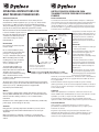
1/2-20 UNF-2B
source when scaling associated
Ø .004 S A
instrumentation.
.75
(19) MIN FULL THREAD
(MIN ZONA ROSCADA)
.17 MAX
(4.3)
Installation
Do not remove protective cap until
ready to install.
Prior to initial installation, verify
correct machining of mounting hole
per Figure 1. Gauge Plug, P/N
200908, is available for this purpose.
When reinstalling make sure that
mounting hole is clear of material.
Dynisco Cleaning Tool Kit, P/N
200100, should be used.
.314
Ø .312
( 7.98 )
7.92
A
La mayoría de los modelos incorporan una
calibración interna (“Rcal”) función que se
utiliza para generar una señal del 80% del
rango total. De este modo se elimina la
necesidad de disponer de una fuente
calibrada de presión para el escalado del
instrumento.
Instalcion
No extraer el capuchón protector hasta que
no esté listo para instalar.
Ø .515 MIN *
(13.1)
.458
Ø .452
11.65
(
)
11.47
.225
(5.72)
45˚
[SNOUT LENGTH - .200] MAX
(LONGITUD BOQUILLA) (5.08)
All Dimensions are in Inches (millimeters)
Antes de la instalación inicial, comprobar
que la mecanización del agujero sea
correcta según Figura 1. Para esta
verificación disponemos del utillaje “Gauge
Plug, P/N 200908.”
En sucesivas reinstalaciones se deberá
asegurar que el agujero para alojamiento
esté limpio de Material. Para ello deberán
utilizar el equipo “Dynisco Cleaning Tool
Kit P/N200100.”
To prevent galling, lightly coat
(Dimensiones en pulgadas (milimetros))
transducer threads with a high
* FOR EPR SERIES TRANSDUCERS THIS DIMENSION SHOULD BE .715 (18.2)
Para evitar “gripaje” de la rosca, recubrir
temperature anti-seize material. An
los pasos de la rosca ligeramente con un
Figure 1 - Recommended Mounting Well (1/2-20 UNF)
adequate seal, in a properly
material anti-gripaje para alta temperatura.
Figura 1 - Agujero de Montaje Recomendado (1/2-20 UNF)
machined and maintained mounting
En un agujero de alojamiento bien
well, is obtained with 100 in-lbs.
mecanizado, con un buen mantenimiento, un adecuado cierre ó estanqueidad se
mounting torque. Maximum recommended
obtendrá con un par de clerre de 100 pulgada-Libra. El Par máximo de cierre es
torque is 500 in-lbs.
de 500 pulgada-Libra
The electronics housing should be secured, with the enclosed mounting
bracket (P/N 200941), in an area where the ambient temperature will not
exceed 250˚F (121˚C). (Mounting bracket not supplied with
PT420A/PT460E or EPR models.)
El cabezal electrónico deberá asegurarse mediante el soporte de montaje
(P/N200941) incluido, en una zona donde la temperatura ambiente no exceda los
121˚C (250˚F). (Los soportes de montaje no se incluyen para los PT420A/PT460E
ni en los modelos EPR).
Wiring
Cableado
Use 6 conductor, shielded cable. Attach cable shield to ground at one
end only. NOTE: DYNISCO cable assemblies are constructed with shield
wired to transducer mating connector, so do not attach shield to
instrument.
Utilizar cable apantallado de 6 conductores. Conexionar a Tierra en un solo
extremo. NOTA: El cable de DYNISCO hacia el conector está construido con cable
apantallado, por lo tanto, no sujete este cable al instrumento.
Excitation is from a well regulated 10 VDC, recommended, (12 VDC max.)
power supply. (Lower voltage can be used.)
Start-Up
Bring system to operating temperature and with no pressure, follow
recommended procedures with instrumentation for zero and span
adjustment.
Make sure that there is sufficient "soak time" to assure that any
material at the tip of the transducer is molten before extruder drive is
started.
Se recomienda que la Excitación proceda de un suministro eléctrico bien
regulado de 10 VDC, (12 VDC máxima). (Voltajes inferiores pueden ser utilizados).
Puesta En Marcha
Llevar el sistema a la temperatura de trabajo y sin presión, seguir los
procedimientos recomendados para el ajuste del “cero” y el “span” para el
instrumento en cuestión.
Asegurarse de que el tiempo de espera desde que la instalación está a
temperatura de trabajo hasta que se ponga en marcha la extrusora, sea el
suficiente para que cualquier material en contacto con el diafragma del
transductor, esté completamente fundido.
Extraccion
Removal
Transducer should only be removed
when polymer is hot and liquid. Wipe
tip with a soft cloth immediately. The
melt pressure transducer must be
removed before using an abrasive
material or wire brush to clean the
extruder barrel. Clean mounting well
before attempting to reinstall
transducer with Dynisco Mounting
Well Cleaning Tool Kit, P/N 200100.
6-Pin Connector
PT460 Series
8-Pin Connector
PT420 Series
Conector 6-Pin
Serie PT460
Conector 8-Pin
Serie PT420
Thermocouple
The models TPT463E, TPT463XL,
MRT463, and TPT432A include a
thermocouple in the rigid stem. The
standard Type J (iron-constantan) T/C
junction is just behind the flush
diaphragm at the tip of the transducer.
This senses the temperature at that
point. For accurate temperature
measurement of the melt stream, use
a separate immersion-type
thermocouple, such as Dynisco TB422
fixed depth series or (G)RMT
adjustable models.
Sólo debería extraerse el Transductor
mientras el polímero está caliente y
líquido. Una vez extraído y mediante un
suave textil limpiar el diafragma con
mucha delicadeza. El transductor deber·
extraerse ó desmontarse antes de que se
utilicen materiales abrasivos ó cepillos
de púas para la limpieza de la
extrusora/husillos. Antes de reinstalar el
Transductor limpiar correctamente el
aguajero de alojamiento mediante el
equipo “Dynisco Mounting Well Cleaning
Tool Kit, P/N200100.”
Termopares
A = Sig + Red/Rojo
A = Exc +
White/Blanco
B = Sig - Black/Negro
B = Sig +
Red/Rojo
C = Exc + White/Blanco
C = Exc -
Green/Verde
D = Exc - Green/Verde
D = Sig -
Black/Negro
E = R-Cal
Blue/Azul
E = R-Cal
Blue/Azul
F = R-Cal
Orange/Naranja
F = R-Cal
Orange/Naranja
Mating Connector
The thermocouple assembly can be
removed by loosening the #4-40 cup
Bendix PC06A-10-6S(SR)
point set screw on the side of hex
Dynisco P/N 711600
assembly and pulling the T/C probe,
carefully, straight out, without
twisting. Replacement assemblies are available. When installing the
thermocouple probe assembly, align the slot with the pressure capillary
tube and press into snout until top of probe shoulders flush against
snout. Lock in place with set screw.
Transducer Repair
G = No Connection
No Conexión
H = No Connection
No Conexión
Bendix PC06A-12-8S(SR)
Dynisco P/N 710700
Los modelos TPT463E, TPT463XL,
MRT463 y TPT432A incluyen un Termopar
en la caña rígida del Transductor. El
Termopar tipo J estándar
(Hierro/Constantan) se halla justo
detrás del Diafragma del transductor. Por
tanto, la temperatura se detecta en ese
punto. Para conseguir una medida más
precisa de presión de la corriente de
polímero, se recomienda utilizar un
termopar tipo inmerso, tal como Dynisco
TB422 de profundidad fija ó (G)RMT
modelos ajustables.
El equipo Termopar puede ser extraído
aflojando el #4-40 tornillo en el lateral
del cabezal hexagonal y tirando de la sonda con mucho cuidado, hacia fuera y
sin girarla. Se dispone de conjuntos para sustitución. Cuando se instala el
conjunto de sonda Termopar, deberán alinear la ranura con el tubo del capilar de
presión y presionar hacia el interior de la caña rígida hasta que la parte superior
de la sonda haga tope contra el Diafragma. Se fija mediante el tornillo
correspondiente.
Damaged transducers should be returned to:
Servicio
Dynisco Instruments
Attn: RA#_______________
38 Forge Parkway
Franklin, MA 02038
Questions concerning warranty, repair cost, delivery, and requests for a
RA#, should be directed to the Dynisco Repair Department,
508-541-9400 or e-mail: [email protected]
Please call for a return authorization number (RA#) before returning any
product.
Technical Assistance
Los transductores dañados deberán ser devueltos a:
Dynisco Instruments
Attn: RA#_______________
38 Forge Parkway
Franklin, MA 02038
Cuestiones relacionadas con la Garantía, Coste de reparación, entrega, y
peticiones para un/una (RA#) deberían dirigirse a Dynisco Repair Department,
508-541-9400 ó e-mail: [email protected]
Agradeceremos pidan el Número de Autorización de Devolución (RA#) antes de
proceder a su devolución.
Please call 800-221-2201 or 508-541-9400 or fax 508-541-9436.
Asistencia Tecnica
Warranty
This Dynisco product is warranted under terms and conditions set forth
in the Dynisco Web Pages. Go to www.dynisco.com and click on
“Instruments.” Click “Product Warranty” at the bottom of any page for
complete details.
Installation Instructions for These Models:
Por favor llamen al 800-221-2201 ó 508-541-9400 ó fax 508-541-9436.
Garantía
Este producto Dynisco está garantizado bajos los términos y condiciones
establecidas en las Páginas Web Dynisco. Diríjase a www.dynisco.com y
seleccione “Instruments.” Seleccione después “Product Warranty” en el pie de
cualquier página para obtener información completa.
EPR-3, PT410, PT412, TPT412, PT415, DLX420, DLX422, DLX432,
PT420A, PT422A, TPT432A, MRT460, MRT462, MRT463, PT460E,
PT462E, TPT463E, PT460XL, PT462XL, TPT463XL, DYN-X
38 Forge Parkway Franklin, MA 02038
Tel: 508.541.9400 Fax: 508.541.9436
www.dynisco.com
P/N 974000
08/03 REV. D
ECO #28104