1
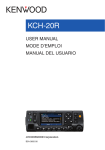
NX-5000 series USER GUIDE GUIDE DE L'UTILISATEUR GUÍA DEL USUARIO The illustration shows the model with an operation panel attached. L’illustration représente le modèle avec un panneau de commande fixé. La ilustración muestra el modelo con un panel de operaciones adjunto. B5A-0868-00 (K) VHF DIGITAL TRANSCEIVER NX-5700 NX-5700(B) UHF DIGITAL TRANSCEIVER NX-5800 NX-5800(B) 700/800MHz DIGITAL TRANSCEIVER NX-5900 NX-5900(B) USER GUIDE This User Guide covers only the basic operations of your radio. Ask your dealer for information on any customized features they may have added to your radio. For using details instruction manual (User Manual), refer to the following URL. http://manual2.jvckenwood.com/en_contents/search/ • • SDTM and microSDTM are trademarks of SD-3C, LLC in the United States. and/ or other countries. The Bluetooth® word mark and logos are registered trademarks owned by Bluetooth SIG, Inc. and any use of such marks by JVC KENWOOD Corporation is under license. Other trademarks and trade names are those of their respective owners. THANK YOU We are grateful you have chosen KENWOOD for your Digital Transceiver applications. CONTENTS NOTICES TO THE USER ................................................................ 3 PRECAUTIONS .......................................................................... 4 TERMINAL DESCRIPTIONS............................................................ 5 UNPACKING AND CHECKING EQUIPMENT .......................................... 6 SUPPLIED ACCESSORIES ............................................................................ 6 PREPARATION .......................................................................... 7 ORIENTATION ........................................................................... 9 OPERATION PANEL (ATTACHED PANEL OR KCH-19) ................................... 9 DISPLAY ..................................................................................................... 10 BASIC OPERATION ................................................................... 13 SWITCHING POWER ON/ OFF..................................................................... 13 ADJUSTING THE VOLUME.......................................................................... 13 SELECTING A ZONE AND CHANNEL ........................................................... 13 TRANSMITTING .......................................................................................... 13 RECEIVING ................................................................................................. 13 INFORMATION ON SOFTWARE LICENSE .......................................... 14 2 NOTICES TO THE USER • • • Government law prohibits the operation of unlicensed radio transmitters within the territories under government control. Illegal operation is punishable by fine and/or imprisonment. Refer service to qualified technicians only. Safety: It is important that the operator is aware of, and understands, hazards common to the operation of any transceiver. • • • EXPLOSIVE ATMOSPHERES (GASES, DUST, FUMES, etc.) Turn OFF your transceiver while taking on fuel or while parked in gasoline service stations. Do not carry spare fuel containers in the trunk of your vehicle if your transceiver is mounted in the trunk area. INJURY FROM RADIO FREQUENCY TRANSMISSIONS Do not operate your transceiver when somebody is either standing near to or touching the antenna, to avoid the possibility of radio frequency burns or related physical injury. DYNAMITE BLASTING CAPS Operating the transceiver within 500 feet (150 m) of dynamite blasting caps may cause them to explode. Turn OFF your transceiver when in an area where blasting is in progress, or where “TURN OFF TWO-WAY RADIO” signs have been posted. If you are transporting blasting caps in your vehicle, make sure they are carried in a closed metal box with a padded interior. Do not transmit while the caps are being placed into or removed from the container. One or more of the following statements may be applicable: FCC WARNING This equipment generates or uses radio frequency energy. Changes or modifications to this equipment may cause harmful interference unless the modifications are expressly approved by the party responsible/ JVC KENWOOD. The user could lose the authority to operate this equipment if an unauthorized change or modification is made. INFORMATION TO THE DIGITAL DEVICE USER REQUIRED BY THE FCC This equipment has been tested and found to comply with the limits for a Class B digital device, pursuant to Part 15 of the FCC Rules. These limits are designed to provide reasonable protection against harmful interference in a residential installation. This equipment generates, uses and can generate radio frequency energy and, if not installed and used in accordance with the instructions, may cause harmful interference to radio communications. However, there is no guarantee that the interference will not occur in a particular installation. If this equipment does cause harmful interference to radio or television reception, which can be determined by turning the equipment off and on, the user is encouraged to try to correct the interference by one or more of the following measures: • Reorient or relocate the receiving antenna. • Increase the separation between the equipment and receiver. • Connect the equipment to an outlet on a circuit different from that to which the receiver is connected. • Consult the dealer for technical assistance. This device complies with Industry Canada licence-exempt RSS standard(s). Operation is subject to the following two conditions: (1) this device may not cause interference, and (2) this device must accept any interference, including interference that may cause undesired operation of the device. Under Industry Canada regulations, this radio transmitter may only operate using an antenna of a type and maximum (or lesser) gain approved for the transmitter by Industry Canada. To reduce potential radio interference to other users, the antenna type and its gain should be so chosen that the equivalent isotropically radiated power (e.i.r.p.) is not more than that necessary for successful communication. 3 The AMBE+2TM voice coding Technology embodied in this product is protected by intellectual property rights including patent rights, copyrights and trade secrets of Digital Voice Systems, Inc. This voice coding Technology is licensed solely for use within this Communications Equipment. The user of this Technology is explicitly prohibited from attempting to extract, remove, decompile, reverse engineer, or disassemble the Object Code, or in any other way convert the Object Code into a human-readable form. U.S. Patent Nos. #6,199,037, #6,912,495, #8,200,497, #7,970,606, and #8,359,197. Firmware Copyrights The title to and ownership of copyrights for firmware embedded in KENWOOD product memories are reserved for JVC KENWOOD Corporation. PRECAUTIONS Observe the following precautions to prevent fire, personal injury, and transceiver damage. • • • Do not attempt to configure the transceiver while driving; it is too dangerous. Do not disassemble or modify the transceiver for any reason. Do not expose the transceiver to long periods of direct sunlight, nor place it near heating appliances. If an abnormal odor or smoke is detected coming from the transceiver, switch the transceiver power off immediately, and contact your KENWOOD dealer. Use of the transceiver while you are driving may be against traffic laws. Please check and observe the vehicle regulations in your area. Do not use options not specified by KENWOOD. Do not put the plastic bag used for packing of this equipment on the place which reaches a small child's hand. It will become a cause of suffocation if it wears flatly. Do not place the transceiver on unstable surfaces. Keep the volume as low as possible to protect your hearing. Always switch the transceiver power off before installing optional accessories. To dispose of batteries, be sure to comply with the laws and regulations in your country or region. • • • • • • • • • • • • The transceiver operates in 12 V negative ground systems only! Check the battery polarity and voltage of the vehicle before installing the transceiver. Use only the supplied DC power cable or a KENWOOD optional DC power cable. Do not cut and/or remove the fuse holder on the DC power cable. Do not place the microphone cable around your neck while near machinery that may catch the cable. For passenger safety, install the transceiver securely using the supplied or optional mounting bracket and screw set so the transceiver will not break loose in the event of a collision. When using the Transceiver, refer to the “NOTICES TO THE USER” and “PRECAUTIONS”. If the warnings are not observed, there may be the possibility to have any malfunction. In this case, press and hold the Power Switch for 5 seconds or more. If the malfunction persists, ask your dealer. 4 TERMINAL DESCRIPTIONS ACC (D-SUB 25 Pin Connector) Pin No. 1 2 3 Name NC COM1_RXD COM1_TXD I/O — I O Not used Serial Data Input Serial Data Output 4 AUXI/O9 I/O Programmable Function I/O 9 5 DI I Description RS-232C compatible Data Input 6 MI2 I 7 GND — Ground Specification MIC Signal Input 8 AUXI/O8 I/O Programmable Function I/O 8 9 10 11 12 COM2_TXD COM2_RXD GND AUXI/O7/BER_DATA O I — I/O Serial Data Output Serial Data Input Ground Programmable Function I/O 7 13 AUXI/O6/BER_CLK I/O Programmable Function I/O 6 14 SB O DC Power (Switched B) Output 15 AUXO2 O Programmable Function O 2 16 AUXO1 O Programmable Function O 1 17 AFO O AF Signal Output 18 GND — Ground 19 DEO O RX Detected Signal Output 20 AUXI/O5 I/O Programmable Function I/O 5 21 22 23 24 25 AUXI/O4 AUXI/O3 AUXI/O2 AUXI/O1 ME I/O I/O I/O I/O — Programmable Function I/O 4 Programmable Function I/O 3 Programmable Function I/O 2 Programmable Function I/O 1 Mic Ground Input Impedance 100 k Output Impedance 100 0.5 V p-p (Typ.) Input Impedance 20 k 5 mVrms(Typ.) (STD Deviation) Input Impedance 600 Ground Input Impedance 100 k Output Impedance 470 TTL (0V - 5V) Ground Input Impedance 100 k Output Impedance 100 13.6 V ±15% 2 A (Max) Open Drain R (dc): 60 m (Max) Idc (Max)= -500 mA 0.7 V p-p (Typ.) Output Impedance 100 Ground 0.28 Vp-p (Typ.) Output Impedance 100 Input Impedance 100 k Output Impedance 470 Ground Speaker Jack (3.5 mm Phone Jack) 4 W/ 4 Pin No. 1 3 Name I/O O — Description External Speaker Output Ground I/O I — Description DC Power Input Ground Specification 13.6 V ±15% Ground Name I/O I Description Ignition Sense Input Specification 13.6 V ±15% Name I/O O I/O Description Mic Backlight Control USB Serial Data I/O Specification Output Impedance 1 k USB 2.0 13.6 V ±15% 200 mA (Max) Ground Input Impedance 47 k UART TTL (0V to 5V) Ground Input Impedance 600 5 V/ 1 mA (Typ.) Input Impedance 1 k UART TTL (0V to 5V) USB 2.0 High Impedance SPO GND 4 (Min) Ground Specification DC Input Connector Pin No. Red Black Name B GND Ignition Sense Input Terminal Pin No. Yellow B Microphone Jack Pin No. 1 BLC D+ 2 SB O DC Power (Switched B) Output 3 GND PTT TXD ME MIC VBUS HOOK RXD DDM — I O — I I I I I/O I/O Ground PTT PC Serial Data from Radio Mic Ground Mic Signal Input USB VBUS Hook PC Serial Data to Radio USB Serial Data I/O Mic Data Detection 4 5 6 7 8 RF Antenna Terminal 50 impedance GPS Antenna Terminal 50 impedance 5 UNPACKING AND CHECKING EQUIPMENT Note: • The following instructions are for use by your KENWOOD dealer, an authorized KENWOOD service facility, or the factory. Carefully unpack the transceiver. We recommend that you identify the items listed below before discarding the packing material. If any items are missing or have been damaged during shipment, file a claim with the carrier immediately. SUPPLIED ACCESSORIES DC power cable (with fuses) <NX-5700/ NX-5800/ NX-5900 only> . . . . . . . . . . . . . . . 1 • 15 A fuse. . . . . . . . . . . . . . . . . . . . . . . . . . . . . . . . . . . . . . . . . . . . . . . . . . . . . . . . . . . . . . . . . . . 2 Mounting bracket <NX-5700/ NX-5800/ NX-5900 only> . . . . . . . . . . . . . . . . . . . . . . . . 1 Screw set <NX-5700/ NX-5800/ NX-5900 only> • • • • 5 x 16 mm self-tapping screw . . . . . . . . . . . . . . . . . . . . . . . . . . . . . . . . . . . . . . . . . . . . . . . . . . . 4 M4 x 6 mm hex-headed screw with washer . . . . . . . . . . . . . . . . . . . . . . . . . . . . . . . . . . . . . . . . 4 Spring washer . . . . . . . . . . . . . . . . . . . . . . . . . . . . . . . . . . . . . . . . . . . . . . . . . . . . . . . . . . . . . . . 4 Flat washer . . . . . . . . . . . . . . . . . . . . . . . . . . . . . . . . . . . . . . . . . . . . . . . . . . . . . . . . . . . . . . . . . 4 Microphone (with cable) <NX-5700/ NX-5800/ NX-5900 only> • KMC-35. . . . . . . . . . . . . . . . . . . . . . . . . . . . . . . . . . . . . . . . . . . . . . . . . . . . . . . . . . . . . . . . . . . . 1 • Microphone hanger (with 4 x 16 mm self-tapping screws) . . . . . . . . . . . . . . . . . . . . . . . . . . . . . 1 User guide. . . . . . . . . . . . . . . . . . . . . . . . . . . . . . . . . . . . . . . . . . . . . . . . . . . . . . . . . . . 1 6 PREPARATION Various electronic equipment in your vehicle may malfunction if they are not properly protected from the radio frequency energy which is present while transmitting. Typical examples include electronic fuel injection, anti-skid braking, and cruise control. If your vehicle contains such equipment, consult the dealer for the make of vehicle and enlist his/her aid in determining if they will perform normally while transmitting. ■ Connecting the power cable The transceiver operates in 12 V negative ground systems only! Check the battery polarity and voltage of the vehicle before installing the transceiver. 1 Check for an existing hole, conveniently located in the firewall, where the power cable can be passed through. • If no hole exists, use a circle cutter to drill a hole, then install a rubber grommet. 2 Run the power cable through the firewall and into the engine compartment. 3 Connect the red lead to the positive (+) battery terminal and the black lead to the negative (–) battery terminal. • Place the fuse as close to the battery as possible. 4 Coil the surplus cable and secure it with a retaining band. • Be sure to leave enough slack in the cables so the transceiver can be removed for servicing while keeping the power applied. ■ Installing the Transceiver For passenger safety, install the transceiver securely using the supplied or optional mounting bracket and screw set, so the transceiver will not break loose in the event of a collision. Note: • Before installing the transceiver, check how far the mounting screws will extend below the surface. When drilling mounting holes, be careful not to damage vehicle wiring or parts. 1 Mark the position of the holes in the dash, using the mounting bracket as a template. Using a 4.2 mm (5/32 inch) drill bit, drill the holes, then attach the mounting bracket using the supplied screws. • Mount the transceiver within easy reach of the user and where there is sufficient space at the rear of the transceiver for cable connections. 2 Connect the antenna and the supplied power cable to the transceiver. 3 Slide the transceiver into the mounting bracket and secure it using the supplied hex-headed screws. 7 4 Mount the microphone hanger in a location where it will be within easy reach of the user. • The microphone and microphone cable should be mounted in a place where they will not interfere with the safe operation of the vehicle. When replacing the fuse in the DC power cable, be sure to replace it with a fuse of the same value. Never replace a fuse with one that is rated with a higher value. Flat washer 5 x 16 mm Self-tapping screw Spring washer Microphone M4 x 6 mm hex-headed screw with washer RF antenna connector Mounting bracket Power input connector DC power cable Ignition sense cable GPS antenna connector for KRA-40 External speaker jack Black (–) cable Red (+) cable Fuse 12 V vehicle battery ■ Using the microSD memory card To install a microSD memory card on this transceiver, please consult your dealer. • • • microSD memory cards (Class 2 or higher) and microSDHC memory cards (Class 2 or higher) can be used. SDXC memory cards cannot be used. This transceiver is not guaranteed to operate with all microSD memory cards. (Operations are confirmed on memory cards for the following brands: SanDisk, TOSHIBA and Panasonic.) Compensation Disclaimer Data stored on the microSD memory card may be altered or lost due to problems with this transceiver. We do not accept liability in respect of the data stored on your microSD memory card, failure to save the data properly, loss of data, and any direct or indirect damages. 8 ORIENTATION OPERATION PANEL (ATTACHED PANEL OR KCH-19) a d b ef c g h a [ ] (Power) switch Press to switch the transceiver ON or OFF. b [ ] / [ ] keys Press to activate its programmable function. The default key setting is [Volume Up]/ [Volume Down]. c [ ] / [ ] keys Press to activate its programmable function. The default key setting is [Channel Up]/ [Channel Down]. d Illumination sensor Sensor for Auto Dimmer Function. e Microphone jack Insert the microphone plug into this jack. f TX/RX Indicator The indicator lights in different colors to indicate the current status of the transceiver. Lights red while transmitting and green while receiving. g [ ] / [ ] / [ ] / [ ] / [ ] / [ ] / Auxiliary (orange) keys Press to activate their programmable functions. [ ] : The default key setting is [Clear]. [ ] : The default key setting is [Menu]. [ ] : The default key setting is [Squelch Off Momentary]. [ ] : The default key setting is [Zone Down]. [ ] : The default key setting is [Zone Up]. [ ] : The default key setting is [Function]. Auxiliary (orange) : The default key setting is [None]. h Speaker Internal speaker. For details on programming functions to the keys on your transceiver, please contact your dealer or refer to the "User Manual" available from the following URL. http://manual2.jvckenwood.com/en_contents/search/ 9 DISPLAY Basic Frame Function Indicator Area Main Area Key Guide Area Display Area Description Function Indicator Area Displays the various function indicators, signal strength indicator and clock. Main Area Display the information of the transceiver such as Channel number and Zone number. Key Guide Area Display the key functions for [ ], [ ], [ ] and [ ] keys. Function Indicator Indicator Description Displays the signal strength. The channel is using high transmit power. The channel is using medium transmit power. The channel is using low transmit power. In Digital mode (Digital Channel) In Analog mode (Analog Channel) In Digital mode (Mixed Channel) In Analog mode (Mixed Channel) The Bluetooth function is activated. Blinks in the process of turning on Bluetooth. Connected to Bluetooth device. The GPS position is determined. Blinks when the GPS is unable to determine the position. 10 Indicator Description Non-priority Scan or Voting/Site Roaming is in progress. Blinks when the scan is paused. (green icon) Priority Scan is in progress. Blinks when the scan is paused. (red icon) Indicates Priority channel 1 or Priority Monitor ID 1. Indicates Priority channel 2 or Priority Monitor ID 2. Indicates Priority Monitor ID 3. Indicates Priority Monitor ID 4. The current channel is added to the scanning sequence. The current Zone is added to the Multi-Zone scanning sequence. The Scrambler function is activated. The Encryption function is activated. Blinks when receiving an encrypted carrier. The Encryption (AES) function is activated. Blinks when receiving an encrypted carrier. The Encryption (DES) function is activated. Blinks when receiving an encrypted carrier. The Talk Around function is activated. The Monitor or Squelch Off is activated. The External Speaker is activated. The External Speaker (Internal + External) is activated. The Noise Reduction function is activated. Blinks when Noise Reduction is functioning. Blinks when an incoming call matches your Optional Signaling. A message is stored in the memory. Blinks when a new message is received. The microSD memory card is recognized. The microSD memory card is not recognized. The VOX function is activated. 11 Indicator Description The Site Lock function is activated. The Broadcast Call function is activated. The Surveillance function is activated. The selected group is programmed as telephone IDs. Blinks during Auto Telephone search. The Tactical Zone is activated. The Horn Alert function is activated. The Public Address function is activated. The Intercom function is activated. AUX A is activated. AUX B is activated. AUX C is activated. The Lone Worker function is activated. The Compander function is activated. The Operator Selectable Tone function is activated. Blinks during Auto Recording. The Key Lock function is activated. 12 BASIC OPERATION SWITCHING POWER ON/ OFF Press [ ] to switch the transceiver ON. Press [ ] again to switch the transceiver OFF. ADJUSTING THE VOLUME Press the key programmed as [Volume Up] to increase the volume. Press the key programmed as [Volume Down] to decrease the volume. SELECTING A ZONE AND CHANNEL Select the desired zone and channel using the keys programmed as [Zone Up]/ [Zone Down] and [Channel Up]/ [Channel Down]. • • The transceivers may have names programmed for zones and channels. The zone name and channel name can contain up to 16 and 14 characters respectively. While selecting a zone, the zone name will appear above the channel name. If programmed by your dealer, your transceiver will announce the zone and channel numbers as you change them. TRANSMITTING 1 Select the desired zone and channel. 2 Press the PTT switch and speak into the microphone. Release the PTT switch to receive. • • The LED indicator lights red while transmitting and green while receiving a signal. This indicator can also be disabled by your dealer. For best sound quality at the receiving station, hold the microphone approximately 1.5 inches (3 cm to 4 cm) from your mouth. RECEIVING Select the desired zone and channel. If signaling has been programmed on the selected channel, you will hear a call only if the received signal matches your transceiver settings. 13 INFORMATION ON SOFTWARE LICENSE This unit uses a software based on the license below. *zlib LICENSE Copyright (C) 1995-2013 Jean-loup Gailly and Mark Adler This software is provided 'as-is', without any express or implied warranty. In no event will the authors be held liable for any damages arising from the use of this software. Permission is granted to anyone to use this software for any purpose, including commercial applications, and to alter it and redistribute it freely, subject to the following restrictions: 1. The origin of this software must not be misrepresented; you must not claim that you wrote the original software. If you use this software in a product, an acknowledgment in the product documentation would be appreciated but is not required. 2. Altered source versions must be plainly marked as such, and must not be misrepresented as being the original software. 3. This notice may not be removed or altered from any source distribution. Jean-loup Gailly ( [email protected]) Mark Adler ([email protected]) *Libpng LICENSE This copy of the libpng notices is provided for your convenience. In case of any discrepancy between this copy and the notices in the file png.h that is included in the libpng distribution, the latter shall prevail. COPYRIGHT NOTICE, DISCLAIMER, and LICENSE: If you modify libpng you may insert additional notices immediately following this sentence. This code is released under the libpng license. libpng versions 1.2.6, August 15, 2004, through 1.6.8, December 19, 2013, are Copyright (c) 2004, 2006-2013 Glenn Randers-Pehrson, and are distributed according to the same disclaimer and license as libpng-1.2.5 with the following individual added to the list of Contributing Authors Cosmin Truta libpng versions 1.0.7, July 1, 2000, through 1.2.5 - October 3, 2002, are Copyright (c) 2000-2002 Glenn Randers-Pehrson, and are distributed according to the same disclaimer and license as libpng-1.0.6 with the following individuals added to the list of Contributing Authors Simon-Pierre Cadieux Eric S. Raymond Gilles Vollant and with the following additions to the disclaimer: There is no warranty against interference with your enjoyment of the library or against infringement. There is no warranty that our efforts or the library will fulfill any of your particular purposes or needs. This library is provided with all faults, and the entire risk of satisfactory quality, performance, accuracy, and effort is with the user. libpng versions 0.97, January 1998, through 1.0.6, March 20, 2000, are Copyright (c) 1998, 1999 Glenn Randers-Pehrson, and are distributed according to the same disclaimer and license as libpng-0.96, with the following individuals added to the list of Contributing Authors: Tom Lane Glenn Randers-Pehrson Willem van Schaik libpng versions 0.89, June 1996, through 0.96, May 1997, are Copyright (c) 1996, 1997 Andreas Dilger Distributed according to the same disclaimer and license as libpng-0.88, with the following individuals added to the list of Contributing Authors: John Bowler Kevin Bracey Sam Bushell Magnus Holmgren Greg Roelofs Tom Tanner 14 libpng versions 0.5, May 1995, through 0.88, January 1996, are Copyright (c) 1995, 1996 Guy Eric Schalnat, Group 42, Inc. For the purposes of this copyright and license, "Contributing Authors" is defined as the following set of individuals: Andreas Dilger Dave Martindale Guy Eric Schalnat Paul Schmidt Tim Wegner The PNG Reference Library is supplied "AS IS". The Contributing Authors and Group 42, Inc. disclaim all warranties, expressed or implied, including, without limitation, the warranties of merchantability and of fitness for any purpose. The Contributing Authors and Group 42, Inc. assume no liability for direct, indirect, incidental, special, exemplary, or consequential damages, which may result from the use of the PNG Reference Library, even if advised of the possibility of such damage. Permission is hereby granted to use, copy, modify, and distribute this source code, or portions hereof, for any purpose, without fee, subject to the following restrictions: 1. The origin of this source code must not be misrepresented. 2. Altered versions must be plainly marked as such and must not be misrepresented as being the original source. 3. This Copyright notice may not be removed or altered from any source or altered source distribution. The Contributing Authors and Group 42, Inc. specifically permit, without fee, and encourage the use of this source code as a component to supporting the PNG file format in commercial products. If you use this source code in a product, acknowledgment is not required but would be appreciated. A "png_get_copyright" function is available, for convenient use in "about" boxes and the like: printf("%s",png_get_copyright(NULL)); Also, the PNG logo (in PNG format, of course) is supplied in the files "pngbar.png" and "pngbar.jpg (88x31) and "pngnow.png" (98x31). Libpng is OSI Certified Open Source Software. OSI Certified Open Source is a certification mark of the Open Source Initiative. Glenn Randers-Pehrson glennrp at users.sourceforge.net December 19, 2013 *Md5 Copyright (C) 1999, 2000, 2002 Aladdin Enterprises. All rights reserved. This software is provided 'as-is', without any express or implied warranty. In no event will the authors be held liable for any damages rising from the use of this software. Permission is granted to anyone to use this software for any purpose, including commercial applications, and to alter it and redistribute it freely, subject to the following restrictions: 1. The origin of this software must not be misrepresented; you must not claim that you wrote the original software. If you use this software in a product, an acknowledgment in the product documentation would be appreciated but is not required. 2. Altered source versions must be plainly marked as such, and must not be misrepresented as being the original software. 3. This notice may not be removed or altered from any source distribution. L. Peter Deutsch [email protected] 15 ÉMETTEUR-RÉCEPTEUR NUMÉRIQUE VHF NX-5700 NX-5700(B) ÉMETTEUR-RÉCEPTEUR NUMÉRIQUE UHF NX-5800 NX-5800(B) ÉMETTEUR-RÉCEPTEUR NUMÉRIQUE 700/800MHz NX-5900 NX-5900(B) GUIDE DE L'UTILISATEUR Cette Guide de l’utilisateur couvre uniquement les opérations de base de votre radio. Demandez à votre revendeur pour plus d’informations sur la personnalisation des fonctions qu’il pourrait avoir ajoutées à votre radio. Pour utiliser ce manuel d’instruction en détail, reportezvous à l’URL suivante. http://manual2.jvckenwood.com/en_contents/search/ • • SD™ et microSD™ sont des marques commerciales de SD-3C, LLC aux États-Unis et/ou dans d’autres pays. La marque et les logos Bluetooth® sont des marques deposes appartenant à Bluetooth SIG, Inc. et toute utilisation de ces marques par JVCKENWOOD Corporation est sous licence. Les autres marques et noms commerciaux sont ceux de leurs propriétaires respectifs. MERCI Nous sommes heureux que vous ayez choisi KENWOOD pour vos applications d’émetteur-récepteur numériques. TABLE DES MATIÈRES REMARQUES DESTINÉES À L’UTILISATEUR ........................................ 3 PRÉCAUTIONS .......................................................................... 4 DESCRIPTIONS DE BORNE ............................................................ 5 DÉBALLAGE ET VÉRIFICATION DE L’ÉQUIPEMENT ................................ 6 ACCESOIRES FOURNIS ................................................................................ 6 PRÉPARATION .......................................................................... 7 ORIENTATION ........................................................................... 9 PANNEAU DE COMMANDE (PANNEAU FIXÉ OU KCH-19) ............................ 9 AFFICHEUR ................................................................................................. 10 FONCTIONNEMENT DE BASE ....................................................... 13 MISE SOUS/ HORS TENSION ..................................................................... 13 RÉGLAGE DU VOLUME............................................................................... 13 SÉLECTION D’UNE ZONE ET D’UN CANAL ................................................. 13 TRANSMISSION ......................................................................................... 13 RÉCEPTION ................................................................................................ 13 F-2 AVIS AUX UTILISATEURS • • • Une loi gouvernementale interdit l’usage sans licence des émetteurs radio sur les territoires régis par cette autorité gouvernementale. Une utilisation illégale est passible d’amende ou d’emprisonnement. Refer service to qualified technicians only. Sécurité: Il est important que l’opérateur soit au courant des risques usuels associés à l’exploitation d’un émetteur-récepteur. AVERTISSEMENT • • • ATMOSPHÈRES EXPLOSIVES (GAZ, POUSSIÈRE, FUMÉE, etc.) Mettez l’émetteur-récepteur hors tension lorsque vous faites le plein d’essence ou lorsque vous garez votre véhicule dans une station-service. Ne transportez pas de bidons d’essence dans le coffre arrière de votre véhicule si votre émetteur-récepteur est installé dans cette zone. BLESSURES RÉSULTANT DE LA TRANSMISSION DE FRÉQUENCES RADIO Ne faites pas fonctionner l’émetteur-récepteur lorsque quelqu’un se trouve à proximité de ou touche l’antenne, de manière à éviter tout risque de brûlures occasionnées par les radiofréquences et autres blessures connexes. DÉTONATEURS DE DYNAMITE L’exploitation de l’émetteur-récepteur dans un rayon de 150 mètres d’un détonateur de dynamite pourrait provoquer son explosion. Mettez votre émetteur-récepteur hors tension lorsque vous êtes dans une zone de dynamitage en cours ou dans un endroit où des panneaux d’avertissement demandent de mettre les émetteurs-récepteurs hors tension. Si vous transportez des détonateurs dans votre véhicule, assurez-vous qu’ils se trouvent dans des contenants métalliques fermés dont l’intérieur est matelassé. N’émettez jamais pendant qu’on place ou qu’on sort les détonnateurs de leur contenant. Le présent appareil est conforme aux CNR d’Industrie Canada applicables aux appareils radio exempts de licence. L’exploitation est autorisée aux deux conditions suivantes : (1) l’appareil ne doit pas produire de brouillage, et (2) l’utilisateur de l’appareil doit accepter tout brouillage radioélectrique subi, même si le brouillage est susceptible d’en compromettre le fonctionnement. Conformément à la réglementation d’Industrie Canada, le présent émetteur radio peut fonctionner avec une antenne d’un type et d’un gain maximal (ou inférieur) approuvé pour l’émetteur par Industrie Canada. Dans le but de réduire les risques de brouillage radioélectrique à l’intention des autres utilisateurs, il faut choisir le type d’antenne et son gain de sorte que la puissance isotrope rayonnée quivalente (p.i.r.e.) ne dépassepas l’intensité nécessaire à l’établissement d’une communication satisfaisante. La technologie de codage de la voix AMBE +2™ intégrée dans ce produit est protégée par des droits sur la propriété intellectuelle y compris les droits de brevet, les droits d’auteur et les secrets de fabrication du Digital Voice Systems, Inc. Cette technologie de codage de la voix est autorisée uniquement pour une utilisation avec cet équipement de communication. Il est formellement interdit de la part de l’utilisateur de cette technologie d’essayer d’extraire, de retirer, de décompiler, de procéder à une ingénierie inverse, ou de démonter le code objet, ou d’aucune autre manière que ce soit de convertir l’objet code dans un langage humain intelligible. Brevets américains n°. #6,199,037, #6,912,495, #8,200,497, #7,970,606 et #8,359,197. Droits d’auteur du micrologiciel Le titre et la propriété des droits d’auteur pour le micrologiciel intégré dans la mémoire du produit KENWOOD sont réservés pour JVC KENWOOD Corporation. F-3 PRÉCAUTIONS Veuillez respecter les points suivants afin d’éviter les risques d’incendie, de blessure corporelle ou d’endommagement de l’émetteur-récepteur. • • • Ne tentez pas de configurer l’émetteur-récepteur tout en conduisant, car cela est trop dangeureux. Ne démontez et ne modifiez sous aucun cas l’émetteur-récepteur. N’exposez pas l’émetteur-récepteur aux rayons directs du soleil pendant de longues périodes et ne le placez pas près d’appareils chauffants. Si une odeur anormale ou de la fumée est générée par l’émetteur-récepteur, mettez immédiatement l’émetteur-récepteur hors tension et contactez votre revendeur KENWOOD. Il est possible que l’utilisation de l’émetteur-récepteur lors de la conduite soit contraire aux règles de circulation. Veuillez vérifier et respecter les régulations routières de votre pays. N’utilisez pas les options non indiquées par KENWOOD. Ne mettez pas le sac plastique utilisé pour l’emballage de cet équipement dans un lieu à portée de la main d’un petit enfant. Il deviendra une cause de suffocation si on le porte complètement. Ne placez pas l’émetteur-récepteur sur des surfaces instables. Maintenez le volume aussi faible que possible pour protéger votre ouïe. Veillez à toujours mettre l’émetteur-récepteur hors tension avant d’installer des accessoires en option. Pour la mise au rebut des piles, veillez à bien respecter les lois et réglementations en vigueur dans votre pays ou région. • • • • • • • • ATTENTION • • • • Cet émetteur-récepteur fonctionne uniquement avec un système de 12 V à masse négative! Vérifiez la polarité et la tension de la batterie du véhicule avant d’installer l’émetteur-récepteur. Utilisez uniquement le câble d’falimentation CC fourni ou un câble d’alimentation CC KENWOOD en option. Ne pas couper et/ou retirer le support de fusible sur le câble d’alimentation CC. Ne placez le câble du microphone autour de votre cou lorsque vous vous trouvez à proximité d’installations qui pourraient entraîner le câble. AVERTISSEMENT Pour la sécurité du passager, et pour éviter que l’émetteur-récepteur ne se détache en cas de collision, fixez solidement l’émetteur-récepteur en utilisant le support de montage et l’ensemble des vis. Lorsque vous utilisez l’émetteur-récepteur, reportez-vous à “AVIS AUX UTILISATEURS” et à “PRÉCAUTIONS”. Si les avertissement ne sont pas respectés, il peut y avoir un risque de dysfonctionnement. Dans ce cas, appuyez sur le commutateur d’Alimentation et maintenez-le enfoncé pendant 5 secondes ou plus. Si le problème persiste, adressez-vous à votre revendeur. F-4 DESCRIPTION DE LA BORNE ACC (Connecteur D-SUB 25 broches) N° de broche Nom 1 NC 2 COM1_RXD 3 COM1_TXD E/S — E S Description Non utilisé Entrée de données en série Sortie de données en série E/S Entrée/ Sortie de fonction programmable 9 Caractéristiques Compatible RS-232C Impédance d’entrée : 100 k Impédance de sortie : 100 0.5 V p-p (Typ.) Impédance d’entrée : 20 k 5 mVrms (Typ.) ((Déviation STD) Impédance d’entrée : 600 Terre Impédance d’entrée : 100 k Impédance de sortie : 470 4 AUXI/O9 5 DI 6 7 8 AUXI/O8 E/S Entrée/ Sortie de fonction programmable 8 9 10 11 12 13 COM2_TXD COM2_RXD GND AUXI/O7/BER_DATA AUXI/O6/BER_CLK S E — E/S E/S Sortie de données en série Entrée de données en série Terre Entrée/ Sortie de fonction programmable 7 Entrée/ Sortie de fonction programmable 6 14 SB S Sortie d’alimentation CC (Interrupteur B) 15 AUXO2 S Sortie de fonction programmable 2 16 AUXO1 S Sortie de fonction programmable 1 17 AFO S Sortie signal AF 18 GND — Terre 19 DEO S Sortie signal détecté RX 20 AUXI/O5 E/S Entrée/ Sortie de fonction programmable 5 21 22 23 24 25 AUXI/O4 AUXI/O3 AUXI/O2 AUXI/O1 ME E/S E/S E/S E/S — Entrée/ Sortie de fonction programmable 4 Entrée/ Sortie de fonction programmable 3 Entrée/ Sortie de fonction programmable 2 Entrée/ Sortie de fonction programmable 1 Terre Mic Impédance d’entrée : 100 k Impédance de sortie : 470 E/S S — Description Sortie de l’enceinte externe Terre Caractéristiques 4 (Min) Terre E/S E — Description Entrée d’alimentation CC Terre Caractéristiques 13,6 V ±15% Terre E Entrée des données MI2 E Entrée signal MIC GND — Terre TTL (0V - 5V) Terre Impédance d’entrée : 100 k Impédance de sortie : 100 13,6 V ±15% 2 A (Max) Drain ouvert R (dc): 60 m (Max) Idc (Max)= -500 mA 0,7 V p-p (Typ.) Impédance de sortie : 100 Terre 0,28 Vp-p (Typ.) Impédance de sortie : 100 Terre Prise haut-parleur (3,5 mm) 4 W/ 4 N° de broche 1 SPO 3 GND Nom Connecteur d’entrée CC N° de broche Rouge B Noir GND Nom Terminal d’entrée de détection d’allumage N° de broche Jaune B Nom E/S E Description Entrée de détection d’allumage Caractéristiques 13,6 V ±15% Nom E/S S E/S Description Contrôle du rétroéclairage Mic Entrée/ Sortie de données de série USB S Sortie d’alimentation CC (Interrupteur B) — E S — E E E E E/S E/S Terre PTT Données de série PC à la radio Terre Mic Entrée signal Mic USB VBUS Crochet Données de série PC à la radio Entrée/ Sortie de données de série USB Détection de données Mic Caractéristiques Impédance de sortie : 1 k USB 2.0 13,6 V ±15% 200 mA (Max) Terre Impédance d’entrée : 47 k UART TTL (0V à 5V) Terre Impédance d’entrée : 600 5 V/ 1 mA (Typ.) Impédance d’entrée : 1 k UART TTL (0V à 5V) USB 2.0 Impédance élevée Prise microphone N° de broche 1 BLC D+ 2 SB 3 GND PTT TXD ME MIC VBUS HOOK RXD DDM 4 5 6 7 8 Borne d’antenne RF Impédance de 50 Borne d’antenne GPS Impédance de 50 F-5 DÉBALLAGE ET VÉRIFICATION DE L’ÉQUIPEMENT Remarque: • les instructions suivantes sont destinées à votre revendeur KENWOOD, un centre de service agréé KENWOOD ou à l’usine de fabrication. Déballez soigneusement l’émetteur-récepteur. Nous recommandons que vous identifiez les articles de la liste ci-dessous avant de vous débarrasser des matériaux d’emballage. Si un article manque ou a été endommagé pendant l’expédition, remplissez immédiatement un formulaire de plainte auprès du transporteur. ACCESSOIRES FOURNIS Câble d’alimentation CC (avec fusibles) <NX-5700/ NX-5800/ NX-5900 uniquement>. . . . 1 • Fusible 15 A . . . . . . . . . . . . . . . . . . . . . . . . . . . . . . . . . . . . . . . . . . . . . . . . . . . . . . . . . . . . . . . . 2 Support de montage <NX-5700/ NX-5800/ NX-5900 uniquement> . . . . . . . . . . . . . . . . . . . 1 Ensemble de vis <NX-5700/ NX-5800/ NX-5900 uniquement> • • • • Vis taraudeuse 5 x 16 mm . . . . . . . . . . . . . . . . . . . . . . . . . . . . . . . . . . . . . . . . . . . . . . . . . . . . . 4 Vis à tête hexagonale et rondelle M4 x 6 mm. . . . . . . . . . . . . . . . . . . . . . . . . . . . . . . . . . . . . . . 4 Rondelle à ressort. . . . . . . . . . . . . . . . . . . . . . . . . . . . . . . . . . . . . . . . . . . . . . . . . . . . . . . . . . . . 4 Rondelle ordinaire. . . . . . . . . . . . . . . . . . . . . . . . . . . . . . . . . . . . . . . . . . . . . . . . . . . . . . . . . . . . 4 Microphone (avec câble) <NX-5700/ NX-5800/ NX-5900 uniquement> • KMC-35. . . . . . . . . . . . . . . . . . . . . . . . . . . . . . . . . . . . . . . . . . . . . . . . . . . . . . . . . . . . . . . . . . . . 1 • Crochet à microphone (avec vis taraudeuses 4 x 16 mm) . . . . . . . . . . . . . . . . . . . . . . . . . . . . . 1 Guide de l’utilisateur . . . . . . . . . . . . . . . . . . . . . . . . . . . . . . . . . . . . . . . . . . . . . . . . . . . 1 F-6 PRÉPARATION AVERTISSEMENT Divers équipements électroniques de votre véhicule peuvent mal fonctionner s’ils ne sont pas correctement protégés contre l’énergie radiofréquence produite pendant l’émission. Par exemple, l’injection électronique, le dispositif anti-blocage de frein et le régulateur de vitesse automatique. Si votre véhicule contient de tels équipements, consultez le revendeur de votre véhicule et demandez-lui son aide pour déterminer s’ils fonctionneront normalement pendant une émission. ■ Connexion du câble d’alimentation ATTENTION Cet émetteur-récepteur fonctionne uniquement avec un système de 12 V à masse négative! Vérifiez la polarité et la tension de la batterie du véhicule avant d’installer l’émetteur-récepteur. 1 Vérifiez s’il existe déjà un trou placé de façon pratique dans le pare-feu, à travers lequel le câble d’alimentation peut être passé. • S’il n’y a pas de trou, utilisez un trépan pour percer un trou, puis installez un joint en caoutchouc. 2 Faites passer le câble d’alimentation à travers le pare-feu jusqu’au compartiment du moteur. 3 Connectez le fil rouge à la borne positive (+) de la batterie et le fil noir à la borne négative (–) de la batterie. • Enroulez le câble en trop et fixez-le avec une bande de retenue. 4 Coil the surplus cable and secure it with a retaining band. • Assurez-vous de laisser suffisamment de jeu aux câble de façon à ce que l’émetteur-récepteur puisse être retiré pour réparation tout en restant connecté à l’alimentation. ■ Installation de l’émetteur-récepteur AVERTISSEMENT Pour la sécurité du passager, et pour éviter que l’émetteur-récepteur ne se détache en cas de collision, fixez solidement l’émetteur-récepteur en utilisant le support de montage et l’ensemble des vis. Remarque: • Avant d’installer l’émetteur-récepteur, vérifiez jusqu’où iront les vis de montage sous la surface. Quand vous percez des trous de montage, faites attention de ne pas endommager le câblage ou des pièces du véhicule. 1 Marquez la position des trous sur le tableau de bord, en utilisant le support de montage comme repère. En utilisant une mèche de 4,2 mm, percez les trous, puis fixez le support de montage en utilisant les vis fournies. • Montez l’émetteur-récepteur dans un endroit facile à atteindre pour l’utilisateur et où il y a suffisamment d’espace à l’arrière de l’émetteur-récepteur pour les connexions. 2 Connectez l’antenne et le câble d’alimentation fourni à l’émetteur-récepteur. F-7 3 Faites glisser l’émetteur-récepteur dans le support de montage et fixez-le en utilisant les vis à tête hexagonale fournies. 4 Montez le crochet à microphone dans un endroit facile d’accès pour l’utilisateur. • Le microphone et le câble du microphone doivent être montés dans un endroit où ils ne gêneront pas la conduite en toute sécurité du véhicule. ATTENTION Le microphone et le câble du microphone doivent être montés dans un endroit où ils ne gêneront pas la conduite en toute sécurité du véhicule. Rondelle ordinaire Vis taraudeuse 5 x 16 mm Rondelle à ressort Microphone Vis à tête hexagonale et rondelle M4 x 6 mm Connecteur d’antenne RF Connecteur d’entrée de l’alimentation Câble d’alimentation CC Support de montage Câble de détection d’allumage Connecteur d’antenne GPS pour KRA-40 Prise pour hautparleur externe Câble noir (–) Câble rouge (+) Fusible Batterie de véhicule de 12 V ■ Utilisation de la carte mémoire microSD Pour installer une carte mémoire microSD sur cet émetteur-récepteur, veuillez consulter votre revendeur. • • • Les cartes mémoire microSD (classe 2 ou supérieur) et les cartes mémoire microSDHC (classe 2 ou supérieur) peuvent être utilisées. Les cartes mémoire SDXC ne peuvent pas être utilisées. Le fonctionnement de cet émetteur-récepteur n’est pas garanti avec toutes les cartes mémoire microSD. (Le fonctionnement est garanti sur les cartes mémoire pour les marques suivantes : SanDisk, TOSHIBA et Panasonic.) Avis de non-responsabilité de compensation Les données stockées sur la carte mémoire microSD peuvent être modifiées ou perdues à cause de problèmes avec cet émetteurrécepteur. Nous n’acceptons aucune responsabilité en ce qui concerne les données stockées sur votre carte mémoire microSD, l’échec de la sauvegarde correcte des données, la perte des données et de tout dommage direct ou indirect. F-8 ORIENTATION PANNEAU DE COMMANDE (PANNEAU FIXÉ OU KCH-19) a d b ef c g h a Commutateur [ ] (d’alimentation) Appuyez pour mettre l’émetteur-récepteur sous tension ou hors tension. b Touches [ ] / [ ] Appuyez sur la touche pour activer leurs fonctions programmables. Le réglage par défaut de la clé est [Volume haut]/ [Volume bas]. c Touches [ ] / [ ] Appuyez sur la touche pour activer leurs fonctions programmables. Le réglage par défaut de la clé est [Canal haut]/ [Canal bas]. d Capteur d’éclairage Capteur pour fonction Variateur automatique. e Prise microphone Insérez la fiche du microphone dans cette prise. f Indicateur TX/RX Le indicateur s’allume avec des couleurs différentes pour indiquer l’état actuel de l’émetteur-récepteur. S’allume en rouge lors de la transmission et en vert lors de la réception. g Touches [ ] / [ ] / [ ] / [ ] / [ ] / [ ] / auxiliaire (orange) Appuyez sur la touche pour activer leurs fonctions programmables. [ ] : Le réglage par défaut de la clé est [Effacer]. [ ] : Le réglage par défaut de la clé est [Menu]. [ ] : Le réglage par défaut de la clé est [Silencieux désactivé momentané]. [ ] : Le réglage par défaut de la clé est [Zone bas]. [ ] : Le réglage par défaut de la clé est [Zone haut]. [ ] : Le réglage par défaut de la clé est [Fonction]. Auxiliaire (orange) : Le réglage par défaut de la clé est [Aucune]. h Haut-parleur Haut-parleur interne. Pour plus de détails sur les fonctions de programmation des touches de votre émetteurtransmetteur, veuillez contacter votre revendeur ou consultez le mode d’emploi disponible à l’adresse URL suivante. http://manual2.jvckenwood.com/en_contents/search/ F-9 AFFICHEUR Cadre de base Zone d’indicateur de fonction Zone principale Zone de guide des touches Zone d’affichage Description Zone d’indicateur de fonction Affiche les diverses indicateurs de fonction, le témoin de puissance du signal et l’heure. Zone principale Affiche les informations de l’émetteur-récepteur comme le nombre Canal et le nombre Zone. Zone de guide des touches Affiche les fonctions des touches pour [ ], [ ], [ ] et [ ]. Indicateur de fonction Indicateur Description Affiche la force du signal. Le canal utilise une énergie de transmission élevée. Le canal utilise une énergie de transmission moyenne. Le canal utilise une énergie de transmission faible. En mode numérique (Canal numérique) En mode analogique (Canal analogique) En mode numérique (Canal mixte) En mode analogique (Canal mixte) La fonction Bluetooth est activée. Clignote dans le processus d’activation du Bluetooth. Connecté à un dispositif Bluetooth. La position GPS est déterminée. Clignote lorsque le GPS est incapable de déterminer la position. F-10 Indicateur Description Balayage non prioritaire ou Vote / Site Roaming est en cours. Clignote lorsque le balayage s’arrête momentanément. (indicateur vert) Balayage prioritaire est en cours. Clignote lorsque le balayage s’arrête momentanément. (indicateur rouge) Indique le canal prioritaire 1 ou l’ID de l’écran prioritaire 1. Indique le canal prioritaire 2 ou l’ID de l’écran prioritaire 2. Indique l’ID de l’écran prioritaire 3. Indique l’ID de l’écran prioritaire 4. Le canal en cours est ajouté à la séquence de balayage. La zone en cours est ajoutée à la séquence de balayage MultiZone. La fonction Brouilleur est activée. La fonction Encodage est activée. Clignote lors de la réception d’un transporteur crypté. La fonction Encodage (AES) est activée. Clignote lors de la réception d’un transporteur crypté. La fonction Encodage (DES) est activée. Clignote lors de la réception d’un transporteur crypté. La fonction Talk Around est activée La fonction Surveillance ou Silencieux désactivé est activée. Haut-parleur externe est activé. Le haut-parleur externe (interne + externe) est activé. La fonction Réduction du bruit est activée. Clignote lorsque Réduction du bruit fonctionne. Clignote lorsqu’un appel entrant correspond à vos Signal facultatif. Un message est enregistré dans la mémoire. Clignote lorsqu’on reçoit un nouveau message. La carte mémoire microSD est reconnue. La carte mémoire microSD n’est pas reconnue. F-11 Indicateur Description La fonction VOX est activée. La fonction Verrouillage site est activée. La fonction Appel de diffusion est activée. La fonction Surveillance est activée. S’affiche lorsque le groupe sélectionné est programmé comme ID du téléphone. Clignote pendant la recherche téléphonique automatique. La Zone tactique est activé. La fonction Avertissement par klaxon est activée. La fonction Sonorisation est activée. La fonction Intercom est activée. AUX A est activé. AUX B est activé. AUX C est activé. La fonction Travailleur seul est activée. La fonction Compander est activée. La fonction Tonalité sélectionnable par l'opérateur est activée. Clignote pendant Enregistrement automatique. La fonction Verrouillage des touches est activée. F-12 FONCTIONNEMENT DE BASE MISE SOUS/ HORS TENSION Appuyez [ ] pour mettre l’émetteur-récepteur sous tension. Appuyez à nouveau sur [ ] pour mettre l’émetteur-récepteur hors tension. RÉGLAGE DU VOLUME Appuyez sur la touche programmée en tant que [Volume haut] pour augmenter le volume. Appuyez sur la touche programmée en tant que [Volume bas] pour diminuer le volume. SÉLECTION D’UNE ZONE ET D’UN CANALL Sélectionnez la zone et le canal souhaités à l’aide des touches programmées en tant que [Zone haut]/ [Zone bas] et [Canal haut]/ [Canal bas]. • • Le émetteur-transmetteur peuvent avoir des noms programmés pour les zones et les canaux. Le nom de la zone et le nom du canal peuvent contenir respectivement jusqu’à 16 et 14 caractères. Lors de la sélection d’une zone, le nom de la zone apparaîtra audessus du nom du canal. Si votre revendeur l’a ainsi programmé, votre émetteur-récepteur annonce les numéros de zone et de canal à mesure que vous les changez. TRANSMISSION 1 Sélectionnez la zone et le canal voulus. 2 Appuyez sur le commutateur PTT et parlez dans le microphone. Relâchez le commutateur PTT pour recevoir. • • Le voyant DEL s’allume en rouge pendant l’émission et en vert pendant la reception d’un signal. Cet indicateur peut aussi être désactivé par votre revendeur. Pour une meilleure qualité de son à la station de réception, tenez le microphone à environ 1,5 pouces (3 cm à 4 cm) de votre bouche. RÉCEPTION Sélectionnez la zone et le canal voulus. Si la signalisation a été programmé sur le canal sélectionné, vous entendrez un appel uniquement si le signal reçu correspond aux réglages de votre émetteur-récepteur. F-13 TRANSCEPTOR DIGITAL VHF NX-5700 NX-5700(B) TRANSCEPTOR DIGITAL UHF NX-5800 NX-5800(B) TRANSCEPTOR DIGITAL 700/800MHz NX-5900 NX-5900(B) GUÍA DEL USUARIO Este Guía del Usuario sólo cubre las operaciones básicas de su radio. Póngase en contacto con su distribuidor para obtener más información sobre la personalización de características que podrían haberse agregado a su radio. Para ver el manual de instrucciones de detalles de uso, consulte el siguiente URL. http://manual2.jvckenwood.com/en_contents/search/ • • SD™ y microSD™ son marcas comerciales de SD-3C, LLC en los Estados Unidos y/o en otros países. La marca denominativa y los logos de Bluetooth® son marcas comerciales registradas propiedad de Bluetooth SIG, Inc. y cualquier uso de dichas marcas por JVC KENWOOD Corporation se encuentra bajo licencia. Otras marcas y nombres comerciales pertenecen a sus respectivos dueños. MUCHAS GRACIAS Estamos muy agradecidos por su elección de KENWOOD para sus aplicaciones transceptor digital. CONTENIDO AVISOS AL USUARIO................................................................... 3 PRECAUCIONES ........................................................................ 4 DESCRIPCIONES DEL TERMINAL .................................................... 5 DESEMBALAJE Y COMPROBACIÓN DEL EQUIPO . ................................ 6 ACCESORIOS SUMINISTRADOS ................................................................. 6 PREPARACIÓN .......................................................................... 7 ORIENTACIÓN ........................................................................... 9 PANEL DE OPERACIONES (PANEL ADJUNTO O KCH-19).. .......................... 9 PANTALLA... ............................................................................................... 10 OPERACIONES BÁSICAS ............................................................ 13 ENCENDIDO Y APAGADO ........................................................................... 13 AJUSTE DEL VOLUMEN.............................................................................. 13 SELECCIÓN DE UNA ZONA Y CANAL.......................................................... 13 TRANSMISIÓN............................................................................................ 13 RECEPCIÓN ................................................................................................ 13 E-2 AVISOS AL USUARIO • • • La ley gubernamental prohibe el uso de radiotransmisores no autorizados dentro de los territorios que se encuentran bajo el control del gobierno. La operación ilegal es castigable mediante multa o encarcelamiento, o ambos. Solicite el servicio solamente a un técnico cualifi cado. Seguridad: Seguridad: Es importante que el operador conozca y entienda los peligros comunes derivados del uso de cualquier transceptor. ADVERTENCIA • • • AMBIENTES EXPLOSIVOS (GASES, POLVO, HUMOS, etc.) Desconecte el transceptor mientras abastece combustible, o cuando haya estacionado en una gasolinera. No transporte recipientes conteniendo combustible de recambio en el portaequipajes de su vehículo si ha instalado su transceptor en el área del portaequipajes. LESIONES OCASIONADAS POR TRANSMISIONES DE RADIOFRECUENCIA No opere su transceptor cuando haya alguna persona cerca o en contacto con la antena para evitar la posibilidad de que se produzcan quemaduras por alta frecuencia o lesiones físicas relacionadas. DETONADORES DE DINAMITA La operación del transceptor dentro de un radio de 150 metros de los detonadores de dinamita podría producir una explosión. Desconecte la alimentación de su transceptor en un sitio donde se estén haciendo voladuras o donde haya carteles con la indicación “APAGAR LOS APARATOS DE RADIOCOMUNICACION BILATERAL”. Si está transportando detonadores en su vehículo, asegúrese de hacerlo en cajas metálicas blindadas con almohadillado interior. No transmita mientras se están poniendo o sacando los detonadores de sus cajas. La tecnología de codificación de voz AMBE+2™ integrada en este producto está protegida por derechos de propiedad intelectual incluyendo los derechos de patente, los derechos de autor y secretos comerciales de Digital Voice Systems, Inc. Esta tecnología de codificación de voz otorga licencia para su uso únicamente dentro de este equipo de comunicaciones. Está explícitamente prohibido que el usuario de esta tecnología intente extraer, retirar, descompilar, realizer ingeniería inversa, o desmontar el código objeto, o convertir de cualquier otra manera el código objeto a una forma legible para el ser humano. Los números de patente de los EE.UU. #6,199,037, #6,912,495, #8,200,497, #7,970,606 y #8,359,197. Derechos de propiedad intelectual del firmware La titularidad y propiedad de los derechos de propiedad intelectual del firmware integrado en las memorias de los productos KENWOOD están reservados para JVC KENWOOD Corporation. E-3 PRECAUCIONES Observe las siguientes precauciones para evitar incendios, lesiones personales y daños al transceptor. • • • No intente confi gurar el transceptor mientras conduce, ya que resulta demasiado peligroso. No desmonte ni modifi que el transceptor bajo ningún concepto. No exponga el transceptor a la luz directa del sol durante periodos de tiempo prolongados, ni lo coloque cerca de calefactores. Si detecta un olor anormal o humo procedente del transceptor, desconecte inmediatamente la alimentación y póngase en contacto con su proveedor KENWOOD. El uso del transceptor mientras conduce puede infringir las leyes de tráfi co. Consulte y respete el reglamento de tráfi co de su país. No utilice opciones no indicadas por KENWOOD. No coloque la bolsa de plástico utilizada para el embalaje de este equipo en lugares al alcance de los niños. Si se coloca sobre la cabeza puede causar asfixia. No coloque el transceptor sobre superficies inestables Mantenga el volumen lo más bajo posible para proteger sus oídos. Apague el transceptor antes de instalar los accesorios opcionales. A la hora de desechar las pilas, asegúrese de cumplir con las normas y regulaciones de su país o región. • • • • • • • • PRECAUCIÓN • • • • ¡El transceptor sólo funciona en sistemas de 12 V con negativo a tierra! Compruebe la polaridad y el voltaje de la batería del vehículo antes de instalar el transceptor. Utilice únicamente el cable de alimentación CC suministrado o un cable de alimentación CC opcional de KENWOOD. No corte ni extraiga el porta fusible del cable de alimentación CC. No líe el cable del micrófono alrededor del cuello cuando esté cerca de máquinas que pudieran atrapar el cable. ADVERTENCIA Para la seguridad de los pasajeros, instale el transceptor de forma segura utilizando el soporte de montaje y el juego de tornillos de forma que el transceptor no se suelte en caso de colisión. Al usar el transceptor, consulte “AVISOS AL USUARIO” y “PRECAUCIONES”. Si no respeta las advertencias, podría producirse un funcionamiento incorrecto. En dicho caso, mantenga pulsado el interruptor de alimentación durante 5 segundos o más. Si el problema persiste, póngase en contacto con su distribuidor. E-4 DESCRIPCIONES DEL TERMINAL ACC (Conector D-SUB 25 pines) Número de Pin Nombre 1 NC 2 COM1_RXD 3 COM1_TXD E/S — E S Descripción No utilizado Entrada de datos en serie Salida de datos en serie E/S Entrada/ Salida de función pprogramable 9 4 AUXI/O9 5 DI 6 7 8 AUXI/O8 E/S Entrada/ Salida de función pprogramable 8 9 10 11 12 COM2_TXD COM2_RXD GND AUXI/O7/BER_DATA S E — E/S Salida de datos en serie Entrada de datos en serie Tierra Entrada/ Salida de función pprogramable 7 13 AUXI/O6/BER_CLK E/S 14 SB S Salida de alimentación de CC (Conmutación B) 15 AUXO2 S Salida de función programable 2 16 AUXO1 S Salida de función programable 1 E Entrada de datos MI2 E Entrada de señal MIC GND — Tierra Entrada/ Salida de función pprogramable 6 17 AFO S Salida de señal AF 18 GND — Tierra S Salida de señal detectada RX 19 DEO 20 AUXI/O5 E/S Entrada/ Salida de función pprogramable 5 21 22 23 24 25 AUXI/O4 AUXI/O3 AUXI/O2 AUXI/O1 ME E/S E/S E/S E/S — Entrada/ Salida de función pprogramable 4 Entrada/ Salida de función pprogramable 3 Entrada/ Salida de función pprogramable 2 Entrada/ Salida de función pprogramable 1 Mic Tierra Especificación Compatible con RS-232C Impedancia de entrada 100 k Impedancia de salida 100 0,5 V p-p (Típ.) Impedancia de entrada 20 k 5 mVrms (Típ.) (Desviación ESTÁNDAR) Impedancia de entrada 600 Tierra Impedancia de entrada 100 k Impedancia de salida 470 TTL (0 V a 5 V) Tierra Impedancia de entrada 100 k Impedancia de salida 100 13,6 V ±15% 2 A (Máx.) Drenador Abierto R (dc): 60 m (Máx.) Idc (Máx.)= -500 mA 0,7 V p-p (Típ.) Impedancia de salida 100 Tierra 0,28 Vp-p (Típ.) Impedancia de salida 100 Impedancia de entrada 100 k Impedancia de salida 470 Tierra Conector de altavoz (3,5 mm) (3.5 mm) 4 W/ 4 Número de Pin 1 SPO 3 GND Nombre E/S S — Descripción Salida del altavoz externo Tierra Especificación 4 (Mín.) Tierra E/S E — Descripción Entrada de alimentación CC Tierra Especificación 13,6 V ±15% Tierra Conector de entrada CC Número de Pin Rojo B Rojo GND Nombre Terminal de entrada del sensor de encendido Número de Pin Amarillo B Nombre E/S E Descripción Entrada del sensor de encendido Especificación 13,6 V ±15% E/S S E/S Descripción Control de retroiluminación del micrófono Entrada/ Salida de datos en serie USB Especificación Impedancia de salida 1 k USB 2.0 13,6 V ±15% 200 mA (Máx.) Tierra Impedancia de entrada 47 k UART TTL (0 V a 5 V) Tierra Impedancia de entrada 600 5 V/ 1 mA (Típ.) Impedancia de entrada 1 k UART TTL (0 V a 5 V) USB 2.0 High Impedance Conector de micrófono Número de Pin Nombre 1 BLC D+ 2 SB 3 GND PTT TXD ME MIC VBUS HOOK RXD DDM 4 5 6 7 8 S — E S — E E E E E/S E/S Salida de alimentación de CC (Conmutación B) Tierra PTT Datos en serie de PC a radio Tierra del micrófono Entrada de señal del micrófono USB VBUS Gancho Datos en serie de PC a radio Entrada/ Salida de datos en serie USB Detección de datos del micrófono Terminal de antena RF 50 impedancia Terminal de antena GPS 50 impedancia E-5 DESEMBALAJE Y COMPROBACIÓN DEL EQUIPO Nota: • Las siguientes instrucciones son para su proveedor KENWOOD, un centro de reparaciones autorizado KENWOOD o la fábrica. Desembale el transceptor con cuidado. Recomendamos que antes de desechar el material de embalaje, identifi que los elementos indicados en la lista siguiente. Si falta algo o se ha producido algún daño durante el transporte, presente inmediatamente una reclamación a la empresa de transporte. ACCESORIOS SUMINISTRADOS Cable de alimentación CC (con fusibles) <NX-5700/ NX-5800/ NX-5900 solamente> . . . .1 • Fusible de 15 A . . . . . . . . . . . . . . . . . . . . . . . . . . . . . . . . . . . . . . . . . . . . . . . . . . . . . . . . . . . . . . 2 Soporte de montaje <NX-5700/ NX-5800/ NX-5900 solamente> . . . . . . . . . . . . . . . . . 1 Juego de tornillos <NX-5700/ NX-5800/ NX-5900 solamente> • • • • Tornillo autorroscante de 5 x 16 mm. . . . . . . . . . . . . . . . . . . . . . . . . . . . . . . . . . . . . . . . . . . . . . 4 Tornillos de cabeza hexagonal con arandela de M4 x 6 mm . . . . . . . . . . . . . . . . . . . . . . . . . . . 4 Arandela de resorte . . . . . . . . . . . . . . . . . . . . . . . . . . . . . . . . . . . . . . . . . . . . . . . . . . . . . . . . . . 4 Arandela plana . . . . . . . . . . . . . . . . . . . . . . . . . . . . . . . . . . . . . . . . . . . . . . . . . . . . . . . . . . . . . . 4 Micrófono (con cable) <NX-5700/ NX-5800/ NX-5900 solamente> • KMC-35. . . . . . . . . . . . . . . . . . . . . . . . . . . . . . . . . . . . . . . . . . . . . . . . . . . . . . . . . . . . . . . . . . . . 1 • Horquilla del micrófono (con tornillos autorroscantes de 4 x 16 mm) . . . . . . . . . . . . . . . . . . . . . 1 Guía del usuario . . . . . . . . . . . . . . . . . . . . . . . . . . . . . . . . . . . . . . . . . . . . . . . . . . . . . . 1 E-6 PREPARACIÓN ADVERTENCIA Hay varios equipos electrónicos de su vehículo que podrían funcionar incorrectamente si no se protegen adecuadamente de la energía de radiofrecuencia presente durante la transmisión. Algunos ejemplos típicos son el sistema de inyección electrónica, de antibloqueo de frenos y el control de velocidad. Si su vehículo contiene alguno de estos equipos, consulte al proveedor el modelo de vehículo y pida que le ayuden a determinar si funcionarán correctamente mientras realiza una transmisión. ■ Conexión del cable de alimentación PRECAUCIÓN ¡El transceptor sólo funciona en sistemas de 12 V con negativo a tierra! Compruebe la polaridad y el voltaje de la batería del vehículo antes de instalar el transceptor. 1 Compruebe si hay algún agujero convenientemente situado en el cortafuegos por donde se pueda pasar el cable de alimentación. • Pase el cable de alimentación por el cortafuegos hacia dentro del compartimento del motor. 2 Run the power cable through the firewall and into the engine compartment. 3 Conecte el cable rojo al terminal positivo (+) de la batería y el cable negro al terminal negativo (–) de la batería. • Coloque el fusible lo más cerca posible de la batería. 4 Enrosque y fi je el cable sobrante con una banda de sujeción. • Asegúrese de dejar sufi ciente cable suelto de forma que se pueda extraer el transceptor para su mantenimiento con la alimentación conectada. ■ Instalación el Transceptor ADVERTENCIA Para la seguridad de los pasajeros, instale el transceptor de forma segura utilizando el soporte de montaje y el juego de tornillos de forma que el transceptor no se suelte en caso de colisión. Nota: • Antes de instalar el transceptor, compruebe cuanto se extienden los tornillos por debajo de la superfi cie. Cuando taladre los agujeros de montaje, preste atención para no dañar los cables o las piezas del vehículo. 1 Marque la posición de los agujeros en el salpicadero usando el soporte de montaje como plantilla. Sirviéndose de una broca de taladrar de 4,2 mm, perfore los agujeros, y a continuación fi je el soporte de montaje usando los tornillos suministrados. • Monte el transceptor en un lugar fácilmente al alcance del usuario y con espacio sufi ciente por detrás del mismo para las conexiones de los cables. 2 Conecte la antena y el cable de alimentación suministrado al transceptor. 3 Inserte el transceptor en el soporte de montaje y afi áncelo utilizando los tornillos de cabeza hexagonal suministrados. E-7 4 Monte la horquilla del micrófono en algún lugar que esté fácilmente al alcance del usuario. • El micrófono y el cable del micrófono deben montarse en algún lugar en el que permitan manejar el vehículo de forma segura. PRECAUCIÓN El micrófono y el cable del micrófono deben montarse en algún lugar en el que permitan manejar el vehículo de forma segura. Arandela plana 5 x 16 mm Tornillo autorroscante Arandela de resorte Micrófono Tornillos de cabeza hexagonal con arandela de M4 x 6 mm Conector de antena RF Conector de entrada de alimentación Cable de alimentación CC Soporte de montaje Cable del sensor de encendido Conector de antena GPS por KRA-40 Jack de altavoz externo Cable negro (–) Cable rojo (+) Fusible Batería de 12 V del vehículo ■ Uso de la tarjeta de memoria microSD Para instalar una tarjeta de memoria microSD en este transceptor, póngase en contacto con su distribuidor • • • • Se pueden utilizar tarjetas de memoria microSD (clase 2 o superior) y tarjetas de memoria microSDHC (clase 2 o superior). No se pueden utilizar tarjetas de memoria SDXC. No se garantiza que este transceptor funcione con todas las tarjetas de memoria microSD. (Se confirman las operaciones en tarjetas de memoria para las siguientes marcas: SanDisk, TOSHIBA y Panasonic). Descargo de responsabilidad de compensación Los datos guardados en la tarjeta de memoria microSD se pueden modificar o perder debido a problemas con este transceptor. No aceptamos ninguna responsabilidad en relación con los datos almacenados en su tarjeta de memoria microSD, fallos al guardar los datos correctamente, pérdida de datos, y cualquier daño directo o indirecto. E-8 ORIENTACIÓN PANEL DE OPERACIONES (PANEL ADJUNTO O KCH-19) a d b ef c g h a Interruptor [ ] (alimentación) Pulse para activar o desactivar el transceptor. b Teclas [ ] / [ ] Pulse para activar sus funciones programables. El ajuste predeterminado de la tecla es [Subir volumen]/ [Bajar volumen]. c Teclas [ ] / [ ] Pulse para activar sus funciones programables. El ajuste predeterminado de la tecla es [Subir canal]/ [Bajar canal]. d Sensor de iluminación Sensor para la función Atenuador automático. e Conector de micrófono Inserte la clavija del micrófono en este conector. f Indicador TX/RX El indicador se ilumina en colores diferentes para indicar el estado actual del transceptor. Se ilumina en color rojo mientras transmite y en verde mientras recibe. g Teclas [ ] / [ ] / [ ] / [ ] / [ ] / [ ] / auxiliar (naranja) Pulse para activar sus funciones programables. [ ] : El ajuste predeterminado de la tecla es [Borrar]. [ ] : El ajuste predeterminado de la tecla es [Menú]. [ ] : El ajuste predeterminado de la tecla es [Desactivar silenciamiento momentáneo]. [ ] : El ajuste predeterminado de la tecla es [Zona abajo]. [ ] : El ajuste predeterminado de la tecla es [Zona arriba]. [ ] : El ajuste predeterminado de la tecla es [Función]. Auxiliar (naranja) : El ajuste predeterminado de la tecla es [Ninguno]. h Altavoz Altavoz interno. Para más información acerca de la programación de las funciones de teclas en su transceptor, póngase en contacto con su distribuidor o consulte el manual de instrucciones disponible en el siguiente URL. http://manual2.jvckenwood.com/en_contents/search/ E-9 PANTALLA Marco básico Área del indicador de la función Área principal Área de guía de tecla Área de visualización Descripción Área del indicador de la función Muestra los distintos indicadores de función, el indicador de intensidad de la señal y el reloj. Área principal Muestra la información del transceptor como, por ejemplo, el número Canal y el número Zona. Área de guía de tecla Visualiza las funciones de las teclas [ ], [ ], [ ] y [ ]. Indicador de la función Indicador Descripción Muestra la intensidad de la señal. El canal utiliza transmisión de alta potencia. El canal utiliza transmisión de media potencia. El canal utiliza transmisión de baja potencia. En el modo digital (Canal digital) En el modo analógico (Canal analógico) En el modo digital (Canal mixto) En el modo analógico (Canal mixto) La función Bluetooth está activada. Parpadea durante el proceso de activación de Bluetooth. Conectado a un dispositivo Bluetooth. Se define la posición GPS. Parpadea cuando el sistema GPS no puede determinar la posición. E-10 Indicador Descripción Exploración no prioritario o Votación/ Roaming Sitio está en curso. Parpadea cuando la exploración está en pausa. (indicador verde) Exploración prioritaria está en curso. Parpadea cuando la exploración está en pausa. (indicador rojo) Indica prioridad canal 1 o prioridad Monitor ID 1. Indica prioridad canal 2 o prioridad Monitor ID 2. Indica prioridad Monitor ID 3. Indica prioridad Monitor ID 4. El canal actual se añade a la secuencia de escaneado. La zona actual se añade a la secuencia de exploración multizona. La función Mezclador está activada. La función Cifrado está activada. Parpadea al recibir un portador cifrado. La función Cifrado (AES) está activada. Parpadea al recibir un portador cifrado. La función Cifrado (DES) está activada. Parpadea al recibir un portador cifrado. La función Talk Around está activada. La función Monitor o Desactivar Silenciamiento está activada. El altavoz externo está activado. El altavoz externo (Interno + Externo) está activado. La función Reducción de ruido está activada. Parpadea cuando Reducción de ruido está funcionando. Parpadea cuando una llamada entrante coincide con Señal opcional. Hay un mensaje almacenado en la memoria. Parpadea cuando se recibe un mensaje nuevo. La tarjeta de memoria microSD es reconocida. La tarjeta de memoria microSD no es reconocida. E-11 Indicador Descripción La función VOX está activada. La función Bloqueo de sitio está activada. La función Llamada de Difusión está activada. La función Vigilancia está activada. El grupo seleccionado es programado como los ID de teléfono. Parpadea durante la búsqueda de Teléfono Automática. La Zona Táctica está activada. La función Bocina de alerta está activada. La función Megafonía está activada. La función Intercom está activada. AUX A está activado. AUX B está activado. AUX C está activado. La función Trabajador solo está activada. La función Compansor está activada. La función Tono seleccionable por operador está activada. Parpadea durante Grabación automática. La función Bloqueo de las teclas está activada. E-12 OPERACIONES BÁSICAS ENCENDIDO Y APAGADO Pulse [ ] para activar el transceptor. Vuelva a pulsar [ ] para apagar el transceptor. AJUSTE DEL VOLUMEN ulse la tecla programada como [Subir volumen] para aumentar el volumen. Pulse la tecla programada como [Bajar volumen] para reducir el volumen. SELECCIÓN DE UNA ZONA Y CANAL Seleccione la zona y el canal deseados utilizando las teclas programadas como [Zona arriba]/ [Zona abajo] y [Subir canal]/ [Bajar canal]. • • El transceptor podría tener nombres programados para zonas y canales. El nombre de zona y el nombre del canal pueden contener hasta 16 y 14 caracteres respectivamente. Mientras selecciona una zona, el nombre de zona aparecerá arriba del nombre del canal. Si fue programado por su distribuidor, su transceptor anunciará los números de zona y de canal a medida que los cambie. TRANSMISIÓN 1 Seleccione la zona y el canal deseados. 2 Presione el conmutador PTT y hable al micrófono. Suelte el conmutador PTT para recibir.e. • • El indicador LED se ilumina en color rojo mientras transmite y en verde mientras recibe una señal. Este indicador también puede ser desactivado por el distribuidor. Para obtener una calidad de sonido optima, sujete el transceptor a 1,5 pulgadas (3 ó 4 cm) de la boca. RECEPCIÓN Seleccione la zona y el canal deseados. Si se ha programado la función de señalización en el canal seleccionado, sólo oirá las llamadas en las que la señal recibida coincida con la configuración del transceptor. E-13 © 2015