1
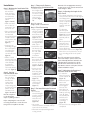
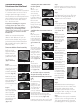
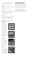
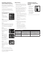
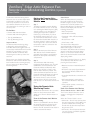
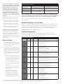
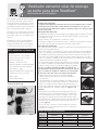
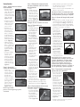
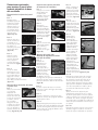
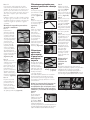
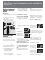
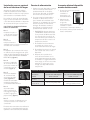
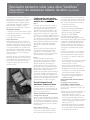
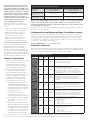
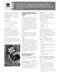
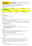
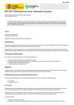
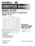
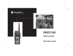
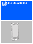
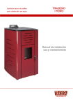
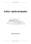
VentSure™ Solar Attic Exhaust Fan—
Roof Mount Unit
Installation Instructions
This fan is designed for new or reroofing work over any properly built
and supported wood roof deck having
adequate nail holding capacity, a smooth
surface, and a roof slope of 4:12 or greater.
Before installing this product, check
local building codes for their roofing
requirements.
The manufacturer will not be responsible
for problems resulting from any deviation
from the recommended application
instructions.
TOOLS REQUIRED
• Ladder
• Reciprocating saw or jig saw
• Power drill with a ½"–1" drill bit
(only one needed)
• Hammer and roofing nail
• Caulk Gun with ASTM D 4586 Type I
Asphalt Roofing Cement
• Measuring tape or ruler
• Permanent marker, sidewalk chalk
or colored pencil
• Roofing knife or box cutter
• Flat pry bar
• Phillips Screwdriver
A
Solar Attic Fan
(not pictured)
A
B
Safety Tips
• Complete all roof preparation prior to bringing the solar fan onto the roof.
• Keep the solar panel covered until after installation. Exposing the solar panel to the
sun will start the fan blades rotating which could cause bodily injury.
Roof Deck
• Maximum 6" width 25⁄32" minimum thickness of wood sheathing
• Minimum 3⁄8" plywood sheathing or 7⁄16" OSB
• Sheathing spaced minimum 1⁄8" and maximum ¼"
• Check local building codes or use decking recommended by American Plywood
Association
Ventilation Requirements
• Ventilation must meet or exceed Federal Housing Administration minimum
property standard.
• Before beginning the installation, calculate the square feet of attic space being
ventilated and select the recommended number of VentSure Solar Attic Exhaust
Fans necessary for moving the required CFM (cubic feet per minute). Depending
on the size of attic space to be ventilated, more than 1 solar fan may be required.
See Fan Sizing Chart below.
• It is critical to ensure there is proper intake ventilation at the
eave or fascia. For each Roof Mount fan, Owens Corning
requires 600 sq. in. of intake.
Note: If it isn’t practical to achieve the required amount of intake
ventilation, Owens Corning recommends adequately sealing the attic
floor and any HVAC ducts in the attic to prevent pulling air from
conditioned space.
Figure 2
• Some attics have more than one walled off or chambered area.
This situation will require fans for each area.
• To maximize the solar fan’s effectiveness you should remove or
block any rooftop static vents, gable end vents, or ridge vents.
This can be accomplished using any roofing underlayment,
ensuring it is securely attached. (Figures 2 and 3)
Box Contents
D
Precautionary Notes
Attic-mounted
Controller
Module
B
4 - Mounting
Screws
C
2 - 8' Cables
D
AC Power
Adapter
C
Figure 1
Positioning
• The solar fan should be positioned to face south or southwest
for optimum performance and should be positioned on an
area of the roof that is not shaded or blocked from the sun for
extended periods throughout the day.
Figure 3
south or southwest
mid-day summer sun
• The solar fan should be installed 18-24" from the ridge of the
roof and as close to mid-point of the house as possible. (Figure 4)
• In the event 2 or more fans are being installed, separate the
fans by at least 15 feet to optimize ventilation.
Figure 4
Fan Sizing Chart
Attic Size
(Sq. Ft.)
1,200
1,600
2,000
2,400
2,800
Number of Roof Mount Fans Required
Low Slope 3:12–4:12
Medium Slope 5:12–8:12 Steep Slope 9:12–12:12
1
1
1
1
1
2
1
1
2
1
2
2
1
2
3
Installation
Step 1. Marking the Installation Hole
• From inside the
attic measure
down from the
roof peak 18-24"
and center this
spot between 2
rafters.
(Figures 5 and 6)
Figure 5
• Make sure there
are no wires or
waterlines in the
area to be cut.
• Drive a nail through
this mark into the
roof deck and
through the shingles
so that it can be
easily found on the
top of the roof.
(Figure 7)
• Locate the nail
protruding through
the roof and place
one of the holes
in the template
over the nail shank.
(Figure 8)
Figure 7
Step 4. Final Positioning
• Apply a generous
amount of asphalt
roofing cement to
the bottom of the
solar fan flashing
(Figure 13). We
recommend using
a roofing cement
meeting ASTM D
4586, Type I.
Figure 8
• Position the solar
fan directly over
the hole using
the “UP” label
as a guide for
orientation.
Figure 6
• Before securing
the solar fan to the
deck make sure
the fan is centered
over the 14" hole.
(Figures 14 and 15)
• With a colored
pencil use the hole
in the opposite end
of the template
to layout the
installation hole.
The result will be a
14" circle. (Figure 9)
Step 2. Cutting
the Installation Hole
• Drill a hole inside
the circle large
enough to insert
the blade of a
reciprocating
saw. Use the
reciprocating saw
to follow the circle
pattern for the
installation hole.
(Figures 10 and 11)
Note: Be careful not
to cut through any
rafters or framing members.
Step 3. Temporarily Remove
Shingles above Installation Hole
• Carefully remove
the shingles above
the hole starting at
a location as close
to the mid-point
of the hole as
possible. (Figure
12)
Figure 12
Note: The removed
shingles will be re-installed later.
Figure 9
Figure 10
Figure 11
Before completing the entire cut, take
necessary precautions to ensure the area
being cut does not fall into the attic.
• Secure the solar
fan to the roof
deck using all 8
installation holes
and the steel
screws provided.
(Figure 16)
• Apply roofing
cement to the
screw heads.
(Figure 17)
Figure 13
Figure 14
Figure 15
Figure 16
Figure 17
Step 5. Re-install Shingles Removed
Earlier
• Re-install the
removed shingles
over the solar fan’s
flashing starting
at the fan and
working up.
(Figure 18)
Figure 18
• Use roofing
cement to seal the nail heads and any
open holes from old nails.
• Hand seal the replaced shingles with
roofing cement.
Reminder: Use an appropriate amount of
roofing cement, as an excessive amount can
cause shingles to blister.
Step 6. Adjusting the Angle of the
Solar Panel
• The optimal adjustment is to have the
solar panel face the sun at a 90° angle at
the midday path of
the sun. The panel
can be re-adjusted Screw A
during winter or
summer seasons if
desired.
• To adjust the
tilt of the panel
remove the screws
(Figure 19) on both
sides of the panel
assembly and set
aside.
Figure 19
re-attach
screw A
• Lift the panel and
swing the panel
braces up to the
desired position
Figure 20
and re-attach the
screws at the new location (Figure 20).
Note: there are 3 positions to choose
from, including parallel to the panel’s
tray.
Note: The solar panel is most effective
when clean and free of dust, leaves, and
debris. Normally rainwater will cleanse the
solar panel but if necessary hose off the
panel between rain showers. Do not use
any abrasive cleaners on the panel, this can
scratch and dull the surface.
Step 7. Adjusting the Rotation of
the Solar Panel on the Tray
• To rotate the
Nut B
panel, loosen the
4 nuts marked “B”.
(Figure 21)
• Rotate the panel
base to the
desired location
and re-tighten
the nuts. The
panel base can
be rotated up to
360° by removing
nuts “B”, lifting
the assembly off
the bolts and
re-positioning
accordingly.
(Figure 22)
Nut B
Figure 21
Figure 22
• Re-attach the nuts and tighten when
completed.
Optional Installation
Location for the Solar Panel
If desired, the solar panel can be
separated from the fan’s base and installed
in a remote location on the roof. This is
sometimes preferred to maximize the
sunlight captured throughout the day.
Please adhere to the following instructions
when installing the solar panel remotely
from the VentSure Solar Attic Exhaust
Fan—Roof Mount Unit.
Important: For installing the solar panel
remotely from the fan’s base, 30-Foot
Extension Wire needs to be purchased
separately from your building materials
supplier. Please ensure you use the extension
wire specific to the VentSure Solar Attic
Exhaust Fan
While we recommend keeping the
distance within 30 feet, the panel can
be placed up to 60 feet away from the
fan’s base without a meaningful drop in
performance. Note: Distances between
30 and 60 feet will require (2) 30-Foot
Extension Wires.
Remove the Solar Panel assembly
Step 1
Remove the 2 tilt
support screws and
lift the solar panel
to gain access to the
junction box and the
solar panel assembly
mounting nuts.
(Figures 23 and 24)
Figure 23
Step 2
Remove the junction
box cover and
remove the 4 screws
holding the wires
Figure 24
and the strain relief
bracket. (Figure 25)
Step 3
Remove the 4 nuts
that attach the solar
panel assembly and
separate the solar
panel assembly from
the fan. (Figure 26)
Step 4
Cut the remaining
wires just above the
wire-way nipple.
DO NOT pull
them out through
the shroud or the
watertight seal will
be destroyed.
(Figure 27)
Figure 25
Figure 26
Figure 27
Attaching the cable extension to
the solar panel
Step 1
Slide the “eye”
connector ends
of the remote
extension adapter
through the hole in
Figure 28
the junction box and
replace the 4 screws.
Make sure the
red wire is on the
positive (+) terminal
typically on the right
Figure 29
side of the box.
(Figures 28 and 29)
Attaching the wire extension kit to
the fan
Step 1
Locate the quick
connector under the
fan shroud. Cut the
zip ties and separate
the quick-connector.
Figure 30
(Figures 30 and 31)
Step 2
Connect the quick
connectors between
the wire extension
kit and the cable
coming from the
motor. The other
remaining cable will
not be used, but can
remain. (Figure 32)
Step 3
Tuck the wire
connection up under
the shroud and tie
wrap securely into
place. (Figure 33)
Figure 31
Figure 32
Figure 33
You are now ready to mount the
solar panel remotely on the roof.
Remote Panel Mounting on Asphalt
Roofs
Step 1
After determining
a location for
mounting the solar
panel, go into the
attic and make sure
the location will
allow a 3⁄8” diameter
Figure 34
hole without hitting
a rafter. Once the location has been
confirmed drive a nail through the roof
deck from the attic side.(Figure 34)
Locate the nail shank on the roof. This will
be the center of the solar mount location.
Step 3
Mark the location and remove the nail.
Drill a 3⁄8” diameter hole where the nail
was removed.
Step 4
Locate the solar panel mounting base over
the 3⁄8” diameter hole lining up the center
hole in the mounting base with the 3⁄8”
diameter hole in the roof deck.
Step 5
Loosen and remove
screw A (both sides)
to allow the panel to
swing away from the
base. Set the screws
aside. (Figure 35)
Step 6
Pull the wire back
through the hole in
the center of the
base to allow the
base to lay flat on
the roof deck.
(Figure 36)
Step 7
Fasten the mounting
base to the roof
deck using the four
(4) 3" galvanized
screws. Seal the tops
of the mounting
screws with an
exterior grade
silicone sealant.
Tilt the panel away
from the base
when installing the
screws. If the panel
is to remain flat
against the base, it
is recommended
to allow the sealant
to completely dry
before it comes in
contact with the
panel. (Figures 37
and 38)
screw A
Figure 35
Figure 36
Figure 37
Figure 38
Step 8
After attaching the mounting base to
the roof deck, feed the connecting cable
through the hole in the roof deck. Leave
enough slack under the solar panel
to allow the panel full travel to avoid
pinching the cable or pulling on the cable
connection during adjustment.
Step 9
Adjust the tilt of the panel to maximize
exposure to the sun throughout the day.
The optimal adjustment is to have the
panel 90 degrees to mid-day path of the
sun. If desired, the angle of the panel can
be adjusted as the seasons change to
maximize sunlight captured.
Step 10
After the panel is adjusted to the desired
position, secure the cable to one of the
support arms using a tie wrap.
Step 11
After the cable is secured, seal the area
around the cable where it enters the roof
deck with exterior grade silicone sealant
to keep water from entering the attic
around the cable.
Step 12
Locate the cable in the attic and drape the
cable from rafter to rafter and connect to
the cable from the fan. Secure any excess
cable to the rafters with tie wires or
coaxial staples.
Remote Panel Mounting for Tile or
Metal Roofs
Step 1
Determine the
location of the
contact points by
positioning the
panel in the desired
area. For Spanish
mount on at
tile roofs, find a
least 2 tiles
position with as
Figure 39
much surface area
coming in contact
with the bottom of
the panel as possible.
The panel must be
mounted on at least
2 rows of tile as
shown. (Figures 39
and 40)
Figure 40
Step 2
Apply enough roof
tile adhesive to
the underside of
the base to firmly
secure the panel to
the surface. Both
surfaces should be
dry and free of any
dirt or solvents.
(Figure 41)
Step 3
The panel can be
tilted into 2 positions
with the adjustment
arm, choose the best
angle and reinstall
the adjusting screws
(screw A). (Figure 42)
Figure 41
reinstall
screw A
Figure 42
Installing an Additional
Solar Panel (Optional)
Depending on the location of the primary
solar panel, you may wish to add an
additional solar panel to increase the
amount of time the fan is powered by
solar energy throughout the day.
For these situations, consider the
VentSure Additional Solar Panel Kit,
available through your building materials
supplier.
VentSure™ Solar Attic Exhaust Fan
Controller Module
Installation Instructions
Installation Guide for the
Controller Module with
Built-in Thermostat and
Humidistat
The Controller Module consists of:
• Attic-mounted Controller Module with
built-in Humidistat and Thermostat
• AC Adapter (required for electric
backup, if desired)
• 8-foot cable
• Remote Access Monitoring Device and
Holster (optional)
3. Thermostat—Turns the fan on,
providing solar power is available,
at or above 80°F, and off at or
below 77°F.
Note: These functions will be active only
when the sun is available to generate
electricity from the solar panel
Installation with Use of House
Electricity—Functionality
Installing the Controller Module with the
AC Power Adapter will provide these
additional benefits:
1. Extends fan operation into the evening
hours
2. Allows fan to operate when
inadequate sunlight is available
3. Intelligently limits the amount of house
electricity to be used for adequate
ventilation
Standard Installation Steps
Optional
Step 1
Bring all Controller
Module components to
the attic.
Figure 1
Pre-Install Check
Please read the instructions before
proceeding with installation. If your Solar
Attic Fan has already been installed, make
sure the Solar Fan is working properly
before installing the Controller Module
components.
Note: The Controller Module can be
installed with or without house electricity.
Standard Installation—Functionality
When performing the standard installation
(without hooking up to house electricity),
the Controller Module will operate only
on power generated by the solar panel and
will provide these functions:
1. Read attic temperature and relative
humidity and display them on the
Controller Module.
2. Humidistat—Turns the fan on,
provided solar power is available, at
or above 75% humidity, and off below
65% humidity.
Step 2
For best results, locate
the Controller Module
near the fan opening
(Figure 1). Mounting
within 2 to 3 feet of
Figure 2
the motor on a nearby
rafter close to the
underside of the roof is recommended.
(Figure 2)
Note: The Controller Module has vents on
either side of the housing that allow the
temperature and humidity sensors to work,
so it is important to locate the Controller
Module with at least 1” of space between it
and the underside of the roof.
Step 3
Use the quick connect leads coming from
the motor to connect to the quick connect
leads of the Controller Module.
Step 4
From underneath the fan, disconnect the
“Quick-Connect” near the motor.
Step 5
Using the cable provided, connect one
wire to the leads coming from the motor
and connect the other end to the leads
marked “Fan” on the Controller Module.
Step 6
Connect the remaining lead coming from
the solar panel to the cable provided and
connect the other end to the lead market
“Solar” on the Controller Module.
Warning: Fan will begin running as soon
as the sun hits the solar panel—keep
everything clear of fan blades.
Step 7
The cable connectors
have been designed
to prevent incorrect
connections. Confirm
the leads going to the
Figure 3
motor connect to the
leads labeled “Fan” on the Controller
Module, and the leads going to the solar
panel connect to the leads labeled “Solar”
on the Controller Module. (Figure 3)
Step 8
Provided there is sunlight to the
solar panel, the LCD display is now
activated and will read the current attic
temperature and relative humidity. When
the Controller Module logic detects the
fan in operation, the fan and solar LEDs
will light up accordingly on the Controller
Module. This will take approximately 30
seconds.
Step 9
Use the included tie
wraps and ¼” or
½” coaxial staples,
available from your
local hardware store
or builders’ supply,
to secure the wiring
harness to the rafter.
(Figures 4 and 5)
The Controller Module
is now installed and
running via power
generated by the solar panel.
Figure 4
Figure 5
Installation with Use of
Optional House Electricity
Be sure to follow all local building codes
when installing the 110V outlet in the
attic. Best practice would be to consult an
electrical contractor.
To utilize the house electricity option
connect the Controller Module to an
AC outlet using the AC Power Adapter
provided.
DO NOT USE AN EXTENSION CORD FOR
THIS CONNECTION
Step 1
Complete steps
1-9 in the standard
installation instructions.
Step 2
Figure 6
Temporarily disconnect
wiring to the solar connectors at the
Controller Module.
Step 3
The AC Power Adapter comes with 4.5
feet of cord. Make sure the 110V outlet is
located within 4.5 feet. (DO NOT USE
AN EXTENSION CORD) (Figure 6)
Step 4
Connect the AC
Power Adapter to the
port on the Controller
Module as shown.
(Figure 7)
Step 5
Plug the AC Power
Adapter into the
110V power source
(outlet). (Figure 8)
The Controller
Module will display
attic temperature and
relative humidity.
Step 6
¼” or ½” coaxial
staples can be used to
secure the wire to the
rafter (not provided).
(Figure 9)
Power Source
1. Whenever available, solar power is
the default power source. On a typical
day with proper sunlight, the fan will
operate until sunset.
2. If solar power is not available, the fan
will not operate unless the Controller
Module is installed with the AC
Power Adapter connected to house
electricity. The fan will continue
operation in the following pre-set
mode for 6 hours:
i. ON for 8 minutes and OFF for 22
minutes in a 30-minute period. This
is the most effective air circulation
frequency to keep the attic
temperature close to the outside
temperature.
Additional Accessory
Available—Remote Attic
Monitor
1. Provides convenient
readout of fan
status, attic
temperature and
attic humidity.
2. Remotely manages
fan’s operating
logic by engaging
or disengaging the
thermal switch.
Remote Attic Monitor
(Optional)
3. One remote can monitor up to 3 fans.
ii. The fan will run for a maximum
of 6 hours on intermittent house
electricity.
iii. The fan will run on solar power
whenever solar power becomes
available again.
iv. After 6 hours of running on
intermittent house electricity,
the fan will be turned off for up
to 12 hours, then turned back
on, assuming solar power is not
available during this period of time.
Power Source Summary
Primary
Power Source
Figure 7
Daytime—with
sufficient solar power
Evening after sunset
Figure 8
Figure 9
Step 7
Reconnect the wiring to the solar
connectors at the Controller Module.
The Controller Module will now utilize
the solar panel AND house electricity to
optimize fan operation.
Solar Fan with Controller Module Solar Fan with Controller Module
WITHOUT AC Adapter connected
WITH AC Adapter connected
Solar power
Solar power
No power available
Intermittent house
electricity for 6 hours
VentSure™ Solar Attic Exhaust Fan
Remote Attic Monitoring Device (Optional)
User Guide
The Remote Attic Monitoring device
allows the user to see the temperature
and humidity conditions in their attic
from nearly anywhere in the home. It
also identifies whether the fan is on or
off and whether it is running on solar or
electric power.
Kit Includes:
• Remote Attic Monitor Holster
• Remote Attic Monitoring Device
• Two (2) AAA Batteries
• Two (2) Mounting Screws
Important Notes
The Remote Attic Monitoring device
is designed to work with VentSure™
Solar Attic Exhaust fans (gable and roof
mount units) installed with the Controller
Module. Do not attempt to use the
Controller Module or Remote Attic
Monitoring device with any other solar
attic fans.
Please ensure your VentSure Solar Attic
Exhaust Fan and Controller Module have
been installed and are working properly
prior to setting up the Remote Attic
Monitoring device.
D
A
E
B
Setting the Remote Attic
Monitor After the Controller
Module
Step 1
The Attic-mounted Controller Module
has 2 slide switches: the one on the left
is for selecting the Radio Frequency (RF)
channel and the one on the right is for
selecting the temperature readout in
Celsius (°C) or Fahrenheit (°F). Select
the same RF channel (choice of 1, 2, or
3) on the Remote Attic Monitor and on
the Controller Module. Both must be on
the same channel in order to send and
receive signals. Also, ensure the desired
temperature readout is selected on the
Controller Module.
Step 2
Remove the back panel of the Remote
Attic Monitor. Insert 2 AAA batteries
(included) in the battery compartment.
Replace the back panel of the battery
compartment.
Step 3
Test the Remote Attic Monitor by
pressing the Status button once. This will
establish the connection between the
Controller Module and Remote Attic
Monitor. You will hear a “beep” every
time the Status button is pressed. This
verifies the Remote Attic Monitor and
Controller Module RF signals are aligned.
If there is not a beep, check that the
RF channel selector is set to the same
channel. If there still isn’t a beep, move
both devices to an alternative channel and
retry.
C
Using the Remote Attic
Monitoring Device
F
G
A
B
C
D
Attic Temperature E Fan Mode
F Status Button
House Power
G Channel Switch
Solar Power
Battery Compartment
Attic Humidity
and Thermo Switch
not pictured
The Remote Attic Monitor has one status
button on the front below the LCD
display, and a Thermo Switch selector on
the back.
Front of the Remote Attic Monitor
Channel Setting
There are 3 available RF channels. Ensure
the same RF channel is selected on the
Controller Module and Remote Attic
Monitor. The RF channel ID must match in
order to transmit information.
Status Button
When the Status button is pressed, a
beep will sound from the Controller
Module to signify a proper connection
between the Controller Module and
Remote Attic Monitor. The Remote Attic
Monitor’s LCD display will show the
following information:
• Attic Temperature
• Attic Relative Humidity
• Fan Mode—ON, OFF, Intermittent,
or Failure
• House Power—ON
• Solar Power—ON
The status will be displayed for
approximately 20 seconds. Press the
Status button again to refresh the
information after 20 seconds. If the beep
doesn’t sound after pressing the Status
button, no connection has been made
with the Controller Module and the LCD
display will go blank.
Check the following if there is no display
on the Remote Attic Monitor after
pressing the Status button:
• Batteries have been installed; Replace if
necessary
• RF channel is properly aligned between
the Controller Module and Remote
Attic Monitor
• Controller Module wire connections are
correct
• AC Power adapter is connected to
the Controller Module for after dark
operation
• If the problem persists, contact us at
1-800-GET-PINK®.
Back of the Remote Attic Monitor
Thermo Switch selector—ON or OFF
The Thermo Switch allows the user to
engage or disengage the temperature
control.
When the Thermo Switch is set to:
• ON mode—Fan will only operate when
the attic temperature reaches 80°F and
power is available. Once running, the
fan will shut off when the temperature
drops below 77°F.
• OFF mode—Fan will operate whenever
a source of power is available, regardless
of attic temperature
Note: The only exception is if solar power
has not been generated for 12 hours AND
the Controller Module is installed with the
AC Power Adapter connected to house
electricity. In this instance, the fan will
operate for 6 hours, then shut off for 12
hours or until solar power is generated.
During each of the 6 hours the fan is
operating via electric backup, the fan will
operate for 8 minutes and then shut off for
22 minutes.
After making a change to the Thermo
Switch on the Remote Attic Monitor:
• Click the Status button and send the
command to the Controller Module.
• Wait 5 seconds for the Controller
Module to change the fan operation.
• Click the Status button again to read
the current fan operation status.
Humidity Control—Always Enabled
The relative humidity sensor is always
enabled (the user cannot disable the
sensor). The fan will be turned on when
attic relative humidity reaches 75%,
regardless of attic temperature. The fan
will turn off when relative attic humidity
drops to 65%.
Source of Power
1. Whenever available, solar power is
the default power source. On a typical
day with proper sunlight, the fan will
operate until sunset.
2. If solar power is not available, the fan
will not operate unless the Controller
Module is installed with the AC power
adapter connected to house electricity.
The fan will then continue to operate
in the following pre-set mode for 6
hours:
I. ON for 8 minutes and OFF for 22
minutes in a 30-minute period. This
is an efficient cycle for trying to
keep the attic temperature close to
the outside temperature.
ii. The cycle will run for a maximum
of 6 hours on intermittent house
electricity.
Power Source Summary
Primary
Power Source
Solar Fan with Controller Module Solar Fan with Controller Module
WITHOUT AC Adapter connected
WITH AC Adapter connected
Daytime—with
sufficient solar power
Evening after sunset
Solar power
Solar power
No power available
Intermittent house
electricity for 6 hours
Note: The primary power source is always SOLAR. If solar power is not available during the
daytime, the primary power source will switch to house electricity (if the Controller Module is
connected to house electricity) for up to 6 hours or until solar power becomes available.
Refer to the LCD Display Summary to interpret the LCD display and the fan’s
operating status.
Multiple Fan Setup—3 or Less Fans
Assign 1 of the 3 available channels to each of the Controller Modules. A beep will come
from the Controller Module that is communicating with the Remote Attic Monitor. The
user can use the same Remote Attic Monitor to control all 3 fans by selecting the correct
RF channel. Do not assign the same RF channel to 2 or more Controller Modules.
4 or more fans—Consult 1-800-GET-PINK®
Additional Information
Please visit our website www.roofing.owenscorning.com for additional product
information and FAQs. You can also call 1-800-GET-PINK® and one of our Customer
Service Representatives will be able to help you.
LCD Display Summary
House
LCD Display Power
(blank)
Solar
Power
ON
Fan
Operation Summary
ON
Solar power is availabe
Fan is not running
Attic temperature is < 80°F
Thermo Switch could be ON
To run fan, switch Thermo Switch to OFF, then press
the Status button twice
ON
ON
(blank)
• Solar power is not available
ON• Fan is powered by house electricity
Intermittent • Fan is running intermittently, currently in the 8-minute
ON mode of the 6-hour cycle
(blank)
• Solar power is not available
• Fan is powered by house electricity
Intermittent
• Fan is running intermittently, currently in the 22-minute
OFF mode of the 6-hour cycle
ON
(blank)
OFF
iii. The fan will run on solar power
whenever solar power becomes
available again.
iv. After 6 hours of running on
intermittent house electricity,
the fan will be turned off for up
to 12 hours, then turned back
on, assuming solar power is not
available during this period of time.
•
•
•
•
•
(blank)
ON
OFF
• Solar power is available
• Fan is running
(blank)
ON
ON
(blank)
Failure
Failure
•
•
•
•
•
•
•
•
•
•
Solar power is not available
Fan is powered by house electricity
Fan is in the 12-hour OFF mode
Fan will restart when solar power becomes available, or
at the end of the 12-hour OFF mode
House electricity is available
Fan is not running
Possible problems:
• Loose wiring
• Motor failure
• Controller Module failure
Solar power is available
Fan is not running
Possible problems:
• Loose wiring
• Motor failure
• Controller Module failure
Pub. No.10017982. Printed in U.S.A. October 2012. THE PINK PANTHER ™ & ©1964 –2012 Metro-Goldwyn-Mayer Studios Inc. All Rights Reserved.
The color PINK is a registered trademark of Owens Corning. ©2012 Owens Corning Roofing & Asphalt ,LLC. All Rights Reserved.
Ventilador extractor solar de montaje
en techo para ático VentSure™
Instrucciones de instalación
Este ventilador está diseñado para trabajos
de colocación de techos nuevos o para la
renovación de techos antiguos que posean
una plataforma de madera adecuada, con
capacidad para sostener clavos, una superficie
lisa y una pendiente de 4:12 o superior.
Antes de colocar este producto, verifique
los códigos locales de construcción con el
fin de saber cuáles son los requisitos para
su techo.
El fabricante no se hará responsable por
los problemas que puedan resultar de
cualquier desviación de lo recomendado
en las instrucciones para la colocación.
HERRAMIENTAS NECESARIAS
• Escalera
• Sierra recíproca o sierra caladora
• Taladro con broca de ½-1 pulg.
(sólo se necesita una)
• Martillo y clavos para techo
• Pistola de calafatear con ASTM D 4586
Tipo I Adhesivo para tejas asfálticas
• Cinta métrica o regla
• Marcador indeleble, tiza o lápiz de color
• Cuchilla para techos o cortador
• Palanca plana
• Destornillador Phillips
Contenido de la caja
A
D
B
C
Ventilador solar para
ático(no figura en la
fotografía)
A Módulo del
controlador de
montaje en ático
B 4 - Tornillos
de montaje
C 2 - Cables de
8 pies
D Adaptador de
corriente de CA
Figura 1
Notas de precaución
Consejos de seguridad
• Complete toda la preparación del techo antes de colocar el ventilador solar en el techo.
• Mantenga el panel solar cubierto hasta después de la instalación. Si se expone el
panel solar al sol, las paletas del ventilador comenzarán a girar y esto puede producir
lesiones corporales.
Estructura base del techo
• Revestimiento de madera con ancho máximo de 6 pulgadas; grosor monísimo de 25⁄32 pulg.
• Revestimiento mínimo de madera contrachapada de 3⁄8 pulg. o panel de fibra
orientada de 7⁄16 pulg.
• Espacio mínimo de revestimiento: 1⁄8 ; máximo: ¼ pulg.
• Consulte los códigos de construcción locales o utilice las recomendaciones para las
estructuras base de techos de la American Plywood Association
Requisitos de ventilación
• La ventilación debe cumplir o exceder los estándares de propiedad mínimos de la
Federal Housing Administration.
• Antes de comenzar con la instalación, calcule los pies cuadrados de espacio del ático
que se va a ventilar se instalará el ventilador y seleccione el número recomendado
de ventiladores extractores solares para ático VentSure necesarios para mover los
pies cúbicos por minuto (CFM) necesarios. Según el tamaño del espacio en el ático
que se va a ventilar, es posible que se necesite más de un ventilador solar. Consulte el
cuadro de tamaños de ventiladores de abajo.
• Es importante asegurar que haya una entrada de aire adecuada
en el alero o imposta. Por cada ventilador de montaje en techos,
Owens Corning requiere una entrada de 600 pulg. cuadradas.
Nota: Si no es práctico alcanzar la cantidad de entrada de aire
requerida, Owens Corning recomienda sellar correctamente el piso del
ático y los conductos de calefacción, ventilación y aire acondicionado
del ático para evitar retirar el aire de los espacios acondicionados.
Figura 2
• Algunos áticos tienen más de una área emparedada o
compartimentada. Esta situación requerirá ventiladores
para cada área.
• Para maximizar la eficacia del ventilador solar, debe remover
o bloquear todos los respiraderos estáticos, los extremos del
hastial o las ventilaciones de cumbrera del techado. Esto se
puede lograr utilizando cualquier membrana impermeable del
techo, asegurando que esté bien asegurada. (Figuras 2 y 3)
Figura 3
Posición
• El ventilador solar se debe ubicar orientado hacia el sur o el
south or southwest
mid-day summer sun
sureste para lograr un rendimiento óptimo y se debe ubicar
en un área del techo que no esté a la sombra o que no esté
expuesta al sol durante períodos extendidos durante el día.
• El ventilador solar se debe instalar entre 18 y 24 pulg. del borde
del techo y tan cerca del punto medio del hogar como sea
posible. (Figura 4)
• En caso de que se instalen 2 o más ventiladores, instale los
Figura 4
ventiladores con una separación de, al menos, 15 pies para
optimizar la ventilación.
Cuadro de tamaños de ventiladores
Dimensiones
del ático (pies
cuadrados)
1,200
1,600
2,000
2,400
2,800
Cantidad de ventiladores de montaje en techos requeridos
Poca pendiente
Pendiente mediana
Pendiente pronunciada
3:12–4:12
5:12–8:12
9:12–12:12
1
1
1
1
1
2
1
1
2
1
2
2
1
2
3
Instalación
Paso 1. Cómo marcar el orificio
de instalación
• Desde el interior
del ático, mida
entre 18 a 24 pulg.
desde la parte
superior del techo
y centre este punto
entre dos vigas.
(Figuras 5 y 6)
• Asegúrese de que
Figura 5
no haya cables o
tuberías de agua
en el área que
vaya a cortar.
• Coloque un
clavo a través de
Figura 6
esta marca en
la estructura del
techo y a través
de las tejas para
poder encontrarlo
fácilmente en la
parte superior del
techo. (Figura 7)
Figura 7
• Ubique el clavo
que sobresale del
techo y ubique uno
de los agujeros de
la plantilla sobre
la punta del clavo.
(Figura 8)
Figura 8
• Coloque un lápiz
de color en el
orificio, en el
extremo opuesto
de la plantilla para
trazar el orificio
de instalación. El
resultado será un
círculo de 14 pulg.
(Figura 9)
Figura 9
Paso 2. Corte del
orificio de instalación
• Perfore un
orificio dentro del
círculo que sea
suficientemente
grande para
insertar la sierra
Figura 10
recíproca. Utilice
la sierra recíproca
para seguir el
patrón del círculo
para el orificio
de instalación.
(Figuras 10 y 11)
Figura 11
Nota: Tenga cuidado
para no cortar ninguna viga o pieza
estructural.
Paso 3. Extracción temporaria de
las tejas ubicadas sobre el orificio
de instalación
• Quite
cuidadosamente
las tejas ubicadas
sobre el orificio;
comience por una
ubicación lo más
cercana posible al
punto medio del
orificio. (Figura 12)
Figura 12
Nota: Las tejas que se
extraigan volverán a instalarse más tarde.
Paso 4. Ubicación fi nal
• Aplique una
cantidad abundante
de adhesivo para
tejas asfálticas en
la parte inferior
del tapajuntas
Figura 13
del ventilador
solar (Figura 13).
Recomendamos
utilizar un adhesivo
para tejas que
cumpla con las
normas ASTM D
Figura 14
4586, Tipo I.
• Ubique el
ventilador solar
directamente
sobre el orificio
utilizando la
etiqueta "UP"
Figura 15
(arriba) como
una guía para la
orientación.
• Antes de asegurar
el ventilador solar
a la estructura,
asegúrese de que
el ventilador esté
centrado sobre el
orificio de 14 pulg.
Figura 16
(Figuras 14 y 15)
• Asegure el
ventilador solar a
la estructura del
techo utilizando
los 8 orificios de
Figura 17
instalación y los
tornillos de acero
que se proporcionan. (Figura 16)
• Aplique adhesivo para tejas en las
cabezas de los tornillos. (Figura 17)
Paso 5. Reinstalación de las tejas
extraídas anteriormente
• Vuelva a instalar
las tejas extraídas
sobre el tapajuntas
del ventilador
comenzando por
el ventilador y
siguiendo hacia
arriba. (Figura 18)
Figura 18
• Utilice adhesivo para techos para sellar
las cabezas de los clavos y cualquier
orificio de clavos viejos.
• Selle a mano las tejas reemplazadas con
adhesivo para techos.
Recordatorio: Utilice una cantidad adecuada
de adhesivo para techos, ya que una cantidad
excesiva puede hacer que las tejas se ampollen.
Paso 6. Ajuste del ángulo del panel
solar
• El ajuste óptimo consiste en lograr que la
cara del panel solar quede enfrentado al
sol a un ángulo de 90SDgr cuando el sol
se encuentra en la posición de mediodía.
El panel se puede volver a ajustar durante
el invierno o el verano, si lo desea.
• Para ajustar la
inclinación del
Tornillo A
panel, quite los
tornillos (Figura
19) ubicados a en
ambos lados del
conjunto del panel.
• Levante el panel
y haga girar los
Figura 19
soportes del panel
Vuelva a
hacia arriba, hasta la
sujetar
posición deseada, y
tornillo
A
vuelva a ajustar los
tornillos en la nueva
posición (Figura
20). Nota: hay 3
posiciones para
elegir, incluida la
posición paralela a
Figura 20
la bandeja del panel.
Nota: El panel solar es alcanza su mayor
efectividad cuando está limpio y libre de hojas
y residuos. Normalmente, el agua de lluvia
limpiará el panel solar, pero, si pasa mucho
tiempo entre una lluvia y otra, puede ser
necesario lavar el panel con una manguera.
No utilice limpiadores abrasivos en el panel, ya
que esto puede rayar y opacar la superficie.
Paso 7. Ajuste de la rotación del
panel solar en la bandeja
• Para hacer girar el
Tuerca B
panel, afloje las 4
tuercas marcadas
con la letra "B".
(Figura 21)
• Gire la base del
panel hasta la
posición que desee
y vuelva a ajustar
Figura 21
las tuercas. La base
del panel se puede
girar hasta 360°
quitando las tuercas
"B", levantando el
conjunto de los
pernos y volviendo
a colocarla la
posición correcta.
Figura 22
(Figura 22)
• Vuelva a sujetar las tuercas y ajústelas
cuando haya terminado.
Ubicaciones opcionales
para montar el panel solar:
techado alejado de la base
del ventilador
Extracción del conjunto del panel
solar
Paso 1
Extraiga los dos
tornillos de ajuste de
inclinación y levante
el panel solar para
obtener acceso a la
caja de conexiones
y al conjunto de las
tuercas de montaje
Figura 23
del panel solar.
(Figuras 23 y 24)
Paso 2
Quite la tapa de la
caja de conexiones
y extraiga los 4
tornillos que ajustan
los cables y el
elemento para aliviar
tensión del cable.
(Figura 25)
Paso 3
Quite las cuatro
tuercas, sujete el
conjunto del panel
solar y separe el
conjunto del panel
del ventilador. (Figura
26)
Paso 4
Corte los cables
restantes tan cerca
de la cubierta como
sea posible. NO los
haga pasar a través
de la cubierta ya que
esto dañará el sello hermético.
(Figura 27)
Figura 24
Figura 25
Figura 26
Figura 27
Sujeción de la extensión del cable
al panel solar
Paso 1
Deslice los extremos
con "ojal" del
adaptador de
extensión remota a
través del orificio de
Figura 28
la caja de conexiones
y vuelva a colocar
los 4 tornillos.
Asegúrese de que
el cable rojo esté en
el terminal positivo
rojo (+) ubicado en
Figura 29
la parte derecha de
la caja. (Figuras 28 y 29)
Sujeción del conjunto del cable
de extensión al ventilador
Paso 1
Coloque el conector
rápido debajo de
la cubierta del
ventilador. Corte los
precintos y separe
Figura 30
el conector rápido.
(Figuras 30 y 31)
Paso 2
Conecte los
conectores rápidos
entre el conjunto de
extensión de cables y
el cable que viene del
motor. El otro cable
restante no se utilizará,
pero se puede dejar.
(Figura 32)
Paso 3
Meta la conexión del
cable arriba, debajo
de la cubierta, y
ajústelo con un
precinto en su lugar.
(Figura 33)
Figura 31
Figura 32
Figura 33
Montaje del panel solar
Montaje de superficie en techos
con tejas de asfalto
Paso 1
Después de
determinar una
ubicación para
montar el panel
solar, vaya al ático y
asegúrese de que esta
ubicación permita
realizar un corte
Figura 34
redondo de 3⁄8 pulg.
de diámetro sin tocar
una viga. Una vez que haya confirmado la
ubicación, coloque un clavo a través de la
estructura del techo desde el lado del ático.
(Figura 34)
Paso 2
Localice la punta del clavo en el techo.
Este será el centro del lugar de montaje
del panel solar.
Paso 3
Marque la ubicación y extraiga el clavo.
Realice un orificio de 3⁄8 pulg. de diámetro
donde quitó el clavo.
Paso 4
Ubique la base del panel solar por encima
del orificio de 3⁄8 pulg. de diámetro alineando
el centro del orificio de la base de montaje
con el orificio de 3⁄8 pulg. de diámetro de la
estructura del techo.
Paso 5
Afloje y extraiga el
tornillo A (ambos
lados) para permitir
que el panel pueda
girarse de la base.
Coloque los tornillos
a un lado. (Figura 35)
Paso 6
Tire del cable a
través del centro de
la base para permitir
que esta quede
totalmente apoyada
sobre la estructura
del techo. (Figura 36)
tornillo A
Figura 35
Paso 7
Figura 36
Ajuste la base
de montaje a la
estructura del
techo utilizando los
cuatro (4) tornillos
galvanizados de 3
pulg. Selle las partes
superiores de los
tornillos de montaje
con un sellador de
Figura 37
silicona para uso
externo. Cuando
instale los tornillos,
incline el panel para
alejarlo de la base.
Si el panel va a
permanecer asentado
contra la base, se
recomienda permitir
que el sellador se
seque completamente
Figura 38
antes de que entre en
contacto con el panel. (Figuras 37 y 38)
Paso 8
Después de sujetar la base de montaje
a la estructura del techo, pase el cable
de conexión a través del orificio de la
estructura del techo. Deje suficiente
espacio debajo del panel solar para dejar
que el panel se desplaza completamente
a fin de evitar pellizcar el cable o jalar la
conexión del cable durante el ajuste.
Paso 9
Ajuste la inclinación del panel para
maximizar la exposición al sol a lo largo
del día. El ajuste óptimo es tener el panel
a 90° en relación con la posición del sol al
mediodía. Si lo desea, el ángulo del panel
se puede ajustar a medida que cambian las
estaciones para maximizar la luz solar que
se captura.
Paso 10
Después de ajustar el panel en la posición
deseada, asegure el cable en uno de los
brazos de soporte utilizando un precinto.
Paso 11
Una vez que esté asegurado el cable,
selle el área de alrededor del cable con
sellador de silicona para uso externo en la
parte en que este entra en la estructura
del techo para evitar que entre agua en el
ático por el espacio que rodea al cable.
Paso 12
Ubique el cable en el ático, tienda el cable
de viga a viga y conéctelo con el cable del
ventilador. Asegure cualquier sobrante de
cable a las vigas con precintos o grapas
coaxiales.
Montaje de superficie para techos
de tejas o metálicos
Paso 1
Determine la
ubicación deseada
para los puntos de
contacto ubicando
el panel en el área
deseada. Para techos
montaje en al
con tejas españolas,
menos 2 tejas
encuentre una
Figura 39
posición para que
la mayor área de
superficie posible
entre en contacto
con la parte inferior
del panel. El panel
debe montarse en, al
menos, 2 filas de tejas,
según se muestra.
(Figuras 39 y 40)
Figura 40
Paso 2
Aplique suficiente
adhesivo para techos
con tejas en la
parte inferior de la
base para asegurar
firmemente el
panel a la superficie.
Ambas superficies
Figura 41
deben estar secas y
libres de suciedad o
solventes. (Figura 41)
Paso 3
El panel se puede
inclinar hasta en 2
Vuelva a
posiciones con el
instalar
brazo de ajuste;
el tornillo A
seleccione el mejor
ángulo y vuelva a
Figura 42
instalar los tornillos
de ajuste (tornillo A). (Figura 42)
Ubicaciones opcionales para
montar el panel solar: montaje
en pared
Se incluyen soportes
para montar el panel
a una pared, si lo
prefiere. (Figuras 43
y 44)
Paso 1
Sujete los soportes
en el panel utilizando
los 4 pernos (F).
(Figura 45)
Paso 2
Según el material
con el que esté
fabricada la
pared, instale el
conjunto en la
pared utilizando
los sujetadores
apropiados
(consulte "accesorios
adicionales" para
obtener más
detalles). (Figura 46)
Ubicaciones
opcionales
para montar
el panel solar:
montaje en
imposta
Figura 43
Figura 44
Perno
F
Figura 45
Consulte
accesorios
opcionales
Figura 46
El juego de montaje
en imposta le permite
instalar el panel
solar del ventilador
Juego opcional de
extractor solar para
montaje
en imposta
™
ático VentSure (el
y soportes
montaje en hastial
y el juego de panel
solar adicional directamente en un tablero
de imposta). Esto le brinda otra opción
para montar el panel en lugar de realizar
el montaje en las tejas del techo o en una
pared exterior.
Sujete los soportes de la imposta en
los soportes de pared totalmente
ensamblados que se incluyen con el
ventilador extractor solar para ático
VentSure™ y la unidad de montaje en
hastial.
Paso 1
En una superficie
plana, oriente el
hastial y los soportes
para pared como
se muestra. (Figura
47) También puede
Figura 47
realizar la instalación en
soportes para pared que ya están sujetados en
el panel (simplemente asegúrese de que estos
estén orientados hacia la misma dirección).
Paso 2
Ubique el orificio
inferior del soporte
para pared (Figura
48), coloque el
perno a través de los
2 soportes y sujete la
tuerca. (Figura 49)
Paso 3
Repita el Paso 2 en
el orificio superior
con otro perno y
otra tuerca. (Figura
50 y 51) Una vez
que las tuercas estén
aseguradas, ajústelas
completamente con
una llave ajustable.
Paso 4
Repita todos los pasos
nuevamente con el
segundo soporte.
Luego, sujete el panel
solar como se describe
en las instrucciones
de instalación que
se incluyen con el
ventilador extractor
solar para ático
VentSure™ (de
montaje en hastial o
en techo) o con el
juego de panel solar
adicional.
Figura 48
Figura 49
Figura 50
Sujete todo el
conjunto en
el tablero de
imposta.
Figura 51
Paso 5
Encuentre la ubicación que desee para el
conjunto completado y sujételo con (4) tornillos
galvanizados de 1,5 pulg. (no se incluyen)
o sujetadores que sean apropiados para el
material de la imposta. (Figura 52 y 53). Una vez
que esté seguro, ajuste el panel como lo desee.
Figura 52
Figura 53
Módulo de control del extractor solar para el ático
VentSure™
Instrucciones de instalación
Guía de instalación para el
módulo del controlador con
termostato y humidistato
incluidos
El módulo del controlador consiste
de lo siguiente:
• Módulo del controlador con termostato
y humidistato incluidos para montaje en
el ático
• Adaptador de corriente de CA (requerida
para respaldo eléctrico, si lo desea)
• Cable de 8 pies
• Dispositivo de monitoreo de acceso
remoto y cartuchera (opcional)
3. Termostato: enciende el ventilador,
siempre que haya energía solar,
con valores de humedad del 80 °F
o superiores y lo apaga cuando la
humedad es inferior al 77 °F.
Nota: Estas funciones estarán activas solamente
cuando haya energía solar disponible para
generar electricidad con el panel solar.
Instalación con uso de la red
eléctrica del hogar: funcionalidad
La instalación del módulo del controlador
con el adaptador de corriente de CA
brindará los siguientes beneficios adicionales:
1. Extiende el funcionamiento del
ventilador en el horario vespertino
2. Permite que el ventilador funcione
cuando la luz solar es insuficiente
3. Limita inteligentemente la cantidad de
electricidad del hogar que se utilizará
para obtener una ventilación adecuada.
Pasos de instalación estándar
Opcional:
Verificación previa a la
instalación
Lea cuidadosamente todas las
instrucciones antes de comenzar la
instalación. Si el ventilador solar para
ático ya ha sido instalado, asegúrese de
que el ventilador solar esté funcionando
correctamente antes de instalar los
componentes del módulo del controlador.
Nota: El módulo del controlador se puede
instalar con electricidad del hogar o sin esta.
Instalación estándar: funcionalidad
Cuando realice la instalación estándar (sin
conectarse a la red eléctrica del hogar), el
módulo del controlador funcionará solamente
con la energía generada por el panel solar y
proporcionará las siguientes funciones:
1. Lectura de la temperatura y la
humedad relativa del ático y
visualización de los valores en el
módulo del controlador.
2. Humidistato: enciende el ventilador,
siempre que haya energía solar,
con valores de humedad del 75 %
o superiores y lo apaga cuando la
humedad es inferior al 65 %.
Paso 1
Traslade todos
los componentes
del módulo del
controlador al ático.
Figura 1
Paso 2
Para obtener mejores
resultados, ubique el
módulo del controlador
cerca de la abertura del
ventilador (Figura 1). Se
Figura 2
recomienda realizar el
montaje a una distancia
de entre 2 y 3 pies del motor, en una viga
cercana a la parte inferior del techo. (Figura 2)
Nota: El módulo del controlador tiene
respiraderos en cada costado de la carcasa
que permiten que funcionen los sensores de
humedad y temperatura, de modo que es
importante ubicar el módulo del controlador
con un espacio de separación de al menos
1 pulg. de la parte inferior del techo.
Paso 3
Utilice los bornes de conexión rápida
que vienen del motor para conectar los
bornes de conexión rápida del módulo
del controlador.
Paso 4
Desde la parte inferior del ventilador,
desconecte la "conexión rápida" ubicada
cerca del motor.
Paso 5
Utilizando el cable que se proporciona,
conecte un cable a los bornes que vienen
del motor y conecte el otro extremo a los
bornes identificados con la palabra "Fan"
(ventilador) en el módulo del controlador.
Paso 6
Conecte el borne restante que vienes
desde el panel solar con el cable que se
proporciona y conecte el otro extremo al
borne identificado con la palabra "Solar"
en el módulo del controlador.
Advertencia: El ventilador comenzará a
funcionar tan pronto como el panel solar
comience a captar la luz del sol: mantenga
despejadas las paletas del ventilador.
Paso 7
Los conectores del
cable han sido diseñados
para evitar conexiones
incorrectas. Confirme
que los bornes que van
Figura 3
hacia el motor estén
conectados con los bornes identificados con
la palabra "Fan" (ventilador) en el módulo
del controlador y que los bornes que van
hacia el panel solar estén conectados con los
bornes identificados con la palabra "Solar"
en el módulo del controlador. (Figura 3)
Paso 8
Siempre que el panel solar reciba la luz
del sol, la pantalla LCD se activará y leerá
la temperatura y la humedad relativa
actuales del ático. Cuando la lógica del
módulo del controlador detecta que
el ventilador está funcionando, los LED
indicadores del ventilador y de energía
solar se encenderán respectivamente en
el módulo del controlador. Esto demora
aproximadamente 30 segundos.
Paso 9
Utilice los precintos que
se incluyen y grapas
coaxiales de ¼ ó ½
pulg., disponibles en
cualquier ferretería o
tienda de suministro
de materiales de
construcción de su
localidad, para asegurar
el mazo de cables a las
vigas. (Figuras 4 y 5)
Figura 4
Figura 5
El módulo del controlador ahora está
instalado y funciona con la energía
generada por el panel solar.
Instalación con uso opcional
de la red eléctrica del hogar
Asegúrese de seguir todos los códigos
locales de construcción cuando instale la
salida de 110 V en el ático. La mejor práctica
sería consultar a un contratista eléctrico.
Para utilizar la opción de electricidad del
hogar, conecte el módulo del controlador
a una salida de CA utilizando el adaptador
de corriente de CA que se proporciona.
NO UTILICE UN ALARGUE ELÉCTRICO
PARA ESTA CONEXIÓN
Paso 1
Complete los pasos 1
a 9 de las instrucciones
de instalación estándar
Paso 2
Desconecte
Figura 6
temporariamente el
cableado hacia los conectores solares en
el módulo del controlador.
Paso 3
El adaptador de corriente de CA incluye
un cable de 4,5 pies. Asegúrese de que la
salida de 110 V esté ubicada dentro de los
4,5 pies. (NO UTILICE UN ALARGUE
ELÉCTRICO) (Figura 6)
Paso 4
Conecte el adaptador
de corriente de CA al
puerto del módulo del
controlador como se
muestra. (Figura 7)
Paso 5
Conecte el adaptador
de corriente de CA
en la fuente de 110 V
(salida). (Figura 8) El
módulo del controlador
mostrará la temperatura
y la humedad relativa del ático.
Paso 6
Se pueden utilizar
grapas coaxiales de ¼
o ½ pulg. para asegurar
el cable a la viga (no se
proporcionan). (Figura 9)
Fuente de alimentación
1. Siempre que esté disponible, la energía
solar es la fuente de alimentación
predeterminada. En un día típico,
con luz solar adecuada, el ventilador
funcionará hasta la puesta del sol.
2. Si no hay energía solar disponible, el
ventilador no funcionará, a menos
que el módulo del controlador esté
instalado con el adaptador de corriente
de CA conectado a la red eléctrica
del hogar. El ventilador continuará
funcionando en el siguiente modo
predeterminado durante 6 horas:
i. ENCENDIDO durante 8 minutos
y APAGADO durante 22 minutos
es un período de 30 minutos. Esta
es la frecuencia de circulación de
aire más efectiva para mantener la
temperatura del ático cercana a la
temperatura exterior.
Accesorio adicional disponible:
monitor de ático remoto
1. Proporciona una lectura cómoda
del estado del
ventilador, la
temperatura y la
humedad del ático.
2. Administra de
manera remota
la lógica de
funcionamiento del Monitor de ático remoto
(Opcional)
ventilador al activar
o desactivar el interruptor térmico.
3. Un monitor remoto puede monitorear
hasta 3 ventiladores.
ii. El ventilador funcionará durante
un máximo de 6 horas con la
electricidad intermitente del hogar.
iii. El ventilador funcionará con energía
solar cuando esta vuelva a estar
disponible.
iv. Después de un período de 6
horas de funcionamiento con la
electricidad intermitente del hogar,
el ventilador se apagará durante 12
horas; luego, se volverá a encender,
teniendo en cuenta que no hay
energía solar disponible durante
este período.
Figura 7
Resumen de la fuente de alimentación
Fuente de
alimentación
primaria
Figura 8
Figura 9
Paso 7
Vuelva a conectar el cableado hacia los
conectores solares en el módulo del
controlador.
El módulo del controlador ahora utilizará el
panel solar y la electricidad del hogar para
optimizar el funcionamiento del ventilador.
Ventilador solar con módulo
del controlador SIN adaptador
de CA conectado
Ventilador solar con módulo
del controlador CON adaptador
de CA conectado
Día: con energía solar
suficiente
Energía solar
Energía solar
Noche, después de la
puesta del sol
No hay energía disponible
Electricidad intermitente
del hogar durante 6 horas
Ventilador extractor solar para ático VentSure™
Dispositivo de monitoreo remoto de ático (Opcional)
Guía del usuario
El dispositivo de monitoreo remoto de
ático permite al usuario ver las condiciones
de temperatura y humedad en el ático
prácticamente desde cualquier lugar del
hogar. Además, identifica si el ventilador
está encendido o apagado y si está
funcionando con energía solar o eléctrica.
El paquete incluye:
• Cartuchera para monitor de ático remoto
• Dispositivo de monitoreo remoto de ático
• Dos (2) baterías AAA
• Dos (2) tornillos de montaje
Notas importantes
El dispositivo de monitoreo remoto de
ático está diseñado para funcionar con los
ventiladores extractores solares para ático
VentSure™ (unidades de montaje en hastial
y en techo) instalados con el módulo del
controlador. No intente utilizar el módulo
del controlador o el dispositivo de monitor
remoto de ático con otros ventiladores
solares para ático.
Asegúrese de que su ventilador extractor
solar para ático VentSure y el módulo del
controlador hayan sido instalados y estén
funcionando correctamente antes de
configurar el dispositivo de monitoreo
remoto de ático.
D
A
E
B
C
G
B
C
D
E
Paso 1
El módulo del controlador de montaje en
ático tiene dos interruptores deslizantes:
el de la izquierda es para seleccionar el
canal de frecuencia de radio (RF) y el de la
derecha es para seleccionar la lectura de
temperatura en Celsius (°C) o Fahrenheit
(°F). Seleccione el mismo canal RF (selección
de 1, 2 ó 3) en el monitor de ático remoto y
en el módulo del controlador. Ambos deben
estar en el mismo canal para enviar y recibir
señales. Además, asegúrese de que se haya
seleccionado la lectura de temperatura
deseada en el módulo del controlador.
Paso 2
Quite el panel trasero del módulo del
controlador. Inserte 2 baterías AAA
(incluidas) en el compartimiento para
baterías. Vuelva a colocar el panel trasero
del compartimiento para baterías.
Paso 3
Pruebe el monitor remoto de ático
presionando una vez el botón "Status"
(estado). Esto establecerá la conexión
entre el módulo del controlador y el
monitor de ático remoto. Escuchará un
pitido cada vez que se presione el botón
"Status". Esto comprueba que las señales
RF del monitor de ático remoto y el
módulo del controlador están alineadas. Si
no escucha un pitido, compruebe que el
selector del canal RF esté configurado en
el mismo canal. Si sigue sin escuchar ningún
pitido, mueva ambos dispositivos hasta un
canal alternativo y vuelva a intentarlo.
Uso del dispositivo de
monitoreo remoto de ático
F
A
Configuración del monitor
remoto de ático después del
módulo del controlador
F Botón "Status"
Temperatura
del ático
(estado)
G Interruptor de canal
Energía del hogar
Energía solar
Compartimiento e
Humedad del ático interruptor térmico no
Modo del ventilador figura en la fotografía
El monitor remoto de ático tiene un
botón de estado en el frente, debajo de
la pantalla LCD y un interruptor selector
térmico en la parte trasera.
Frente del monitor remoto de ático
Configuración del canal
Existen 3 canales RF disponibles. Asegúrese
de que el mismo canal RF esté seleccionado
en el módulo del controlador y el monitor
remoto de ático. La identificación del canal
RF debe coincidir para que se transmita
la información.
Botón "Status" (estado)
Cuando se presiona el botón "Status",
se escucha un pitido desde el módulo
del controlador para representar una
conexión adecuada entre el módulo del
controlador y el monitor remoto de ático.
La pantalla LCD del monitor remoto de
ático mostrará la siguiente información:
• Temperatura del ático
• Humedad relativa del ático
• Modo de ventilador: ENCENDIDO,
APAGADO, intermitente o falla)
• Energía del hogar: ACTIVADA
• Energía solar: ACTIVADA
El estado se mostrará durante,
aproximadamente, 20 segundos. Presione
nuevamente el botón "Status" para actualizar
la información después de 20 segundos. Si
el pitido no suena después de presionar
el botón "Status", esto quiere decir que
no existe una conexión con el módulo del
controlador y la pantalla LCD se pondrá
en blanco.
Controle lo siguiente si no se muestran
los valores del monitor remoto de ático
después de presionar el botón "Status":
• Se instalaron las baterías; cámbielas si
es necesario.
• El canal RF está correctamente alineado
entre el módulo del controlador y el
monitor de ático remoto.
• Las conexiones de los cables del
módulo del controlador son correctas.
• El adaptador de corriente de CA está
conectado con el módulo del controlador
para el funcionamiento nocturno.
• Si el problema persiste, póngase en
contacto con nosotros llamando al
1-800-GET-PINK®.
Parte trasera del monitor remoto
de ático
Interruptor selector térmico:
ACTIVADO o DESACTIVADO
El interruptor térmico permite que el
usuario active o desactive el control de
temperatura.
Cuando se coloca el interruptor térmico en:
• Modo ON (activado): el ventilador
funcionará solamente cuando la
temperatura del ático alcance los 80 °F
y haya energía disponible. Una vez en
funcionamiento, el ventilador se apagará
cuando la temperatura descienda por
debajo de los 77 °F.
• Modo OFF (desactivado): el ventilador
funcionará cuando haya una fuente de
energía disponible, independientemente
de la temperatura del ático.
Nota: La única excepción ocurre cuando no se
ha generado energía solar durante 12 horas y
el módulo del controlador está instalado con el
adaptador de corriente de CA conectado a la red
eléctrica del hogar. En esta instancia, el ventilador
funcionará durante 6 horas y, luego, se apagará
durante 12 horas o hasta que se genere energía
solar. Durante cada una de estas 6 horas, el
ventilador funciona a través del respaldo eléctrico;
el ventilador funcionará durante 8 minutos y,
luego, se apagará durante 22 minutos.
Después de realizar un cambio en el
interruptor térmico del monitor remoto
de ático:
• Haga clic en el botón "Status" y envíe el
comando al módulo del controlador.
• Espere 5 segundos para que el
módulo del controlador cambie el
funcionamiento del ventilador.
• Haga clic nuevamente en el botón
"Status" para leer el estado de
funcionamiento actual del ventilador.
Control de humedad: siempre activado
El sensor de humedad relativa siempre
está activado (el usuario no puede
deshabilitar el sensor). El ventilador se
activará cuando la humedad relativa del
ático alcance el 75 %, independientemente
de la temperatura del ático. El ventilador
se apagará cuando la humedad relativa del
ático disminuya por debajo del 65 %.
Fuente de alimentación
1. Siempre que esté disponible, la energía
solar es la fuente de alimentación
predeterminada. En un día típico,
con luz solar adecuada, el ventilador
funcionará hasta la puesta del sol.
2. Si no hay energía solar disponible, el
ventilador no funcionará, a menos
que el módulo del controlador esté
instalado con el adaptador de corriente
de CA conectado a la red eléctrica
del hogar. El ventilador continuará
funcionando en el siguiente modo
predeterminado durante 6 horas:
I. ENCENDIDO durante 8 minutos y
APAGADO durante 22 minutos es
un período de 30 minutos. Este es un
ciclo eficiente para intentar mantener
la temperatura del ático cercana a la
temperatura exterior.
ii. El ciclo funcionará durante
un máximo de 6 horas con la
electricidad intermitente del hogar.
iii. El ventilador funcionará con energía
solar cuando esta vuelva a estar
disponible.
iv. Después de un período de 6 horas
de funcionamiento con la electricidad
intermitente del hogar, el ventilador
se apagará durante 12 horas; luego,
se volverá a encender, teniendo en
cuenta que no hay energía solar
disponible durante este período.
Resumen de la fuente de alimentación
Fuente de
alimentación
primaria
Ventilador solar con módulo
del controlador SIN adaptador
de CA conectado
Ventilador solar con módulo
del controlador CON adaptador
de CA conectado
Día: con energía solar
suficiente
Energía solar
Energía solar
Noche, después de la
puesta del sol
No hay energía disponible
Electricidad intermitente
del hogar durante 6 horas
Nota: La fuente de alimentación primaria siempre es SOLAR. Si no hay energía solar disponible
durante el día, la fuente de alimentación primaria cambiará a la red eléctrica del hogar (si el
módulo del controlador está conectado a esta) hasta un máximo de 6 horas o hasta que vuelva
a estar disponible la energía solar.
Consulte el Resumen de la pantalla LCD para interpretar la pantalla LCD y el estado de
funcionamiento del ventilador.
Configuración de ventiladores múltiples: 3 ventiladores o menos
Asigne 1 de los 3 canales disponibles para cada uno de los módulos del controlador. Se
escuchará un pitido del módulo del controlador que indica que se está comunicando con
el monitor remoto de ático. El usuario puede utilizar el mismo monitor remoto de ático
para controlar los 3 ventiladores seleccionando el canal RF correcto. No asigne el mismo
canal RF a 2 o más módulos del controlador.
4 o más ventiladores Consulte 1-800-GET-PINK®
Información adicional
Visite nuestro sitio web www.roofing.owenscorning.com para obtener información adicional
sobre el producto y ver las preguntas frecuentes. También puede llamar a 1-800-GET-PINK®
y uno de nuestros Representantes de atención al cliente podrá ayudarlo.
Resumen de la pantalla LCD
Pantalla
LCD
Energía
Energía
del hogar solar
Ventilador
(blank)
(blank)
ON
ON
ON
OFF
Resumen del funcionamiento
• La energía solar está disponible.
• El ventilador está funcionando.
•
•
•
•
•
La energía solar está disponible
El ventilador no está funcionando.
La temperatura del ático es inferior a < 80 °F
El interruptor térmico puede estar ACTIVADO
Para activar el ventilador, cambie el interruptor térmico a
APAGADO; luego, presione el botón "Status" dos veces.
ON
• La energía solar no está disponible.
• El ventilador es activado por la electricidad del hogar.
ON(blank)
• El ventilador está funcionando intermitentemente,
Intermittent
actualmente en el modo ACTIVADO de 8 minutos del ciclo
de 6 horas.
ON
• La energía solar no está disponible.
• El ventilador es activado por la electricidad del hogar.
(blank) Intermittent • El ventilador está funcionando intermitentemente,
actualmente en el modo DESACTIVADO de 22 minutos
del ciclo de 6 horas.
ON
(blank)
ON
(blank)
ON
(blank)
OFF
•
•
•
•
La energía solar no está disponible.
El ventilador es activado por la electricidad del hogar.
El ventilador está en el modo APAGADO de 12 horas.
El ventilador se reiniciará cuando la energía solar esté
disponible, o al final del modo DESACTIVADO de 12 horas.
Failure
• La electricidad del hogar está disponible.
• El ventilador no está funcionando.
• Posibles problemas:
• Cableado flojo
• Falla del motor
• Falla del módulo del controlador
Failure
• La energía solar está disponible.
• El ventilador no está funcionando.
• Posibles problemas:
• Cableado flojo
• Falla del motor
• Falla del módulo del controlador
Pub. N.º 10017982. Impreso en EE. UU. Octubre de 2012. THE PINK PANTHER ™ & ©1964 –2012 Metro-Goldwyn-Mayer Studios Inc. Todos los derechos reservados.
El color PINK es una marca comercial registrada de Owens Corning. ©2012 Owens Corning Roofing & Asphalt ,LLC. Todos los derechos reservados.