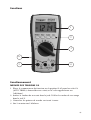
1
mM
AVO410
Digital multimeter
Digitale Multimeter
Multimèter numérique
Multímetro digitales
Digitale multimeter
User manual
Bedienungsanleitung
Manuel utilisateur
Guía del usuario
Gebruikershandleiding
1
G
SAFETY WARNINGS
Safety warnings must be read and understood before instrument is used.
The following safety information must be observed to insure maximum
personal safety during the operation of this meter:
■ Do not use in wet environments.
■ Measurements beyond the maximum selected range must not be attempted.
■ Extreme care must be taken when measuring above 50 V, especially on live
bus-bars.
■ To measure voltage, the instrument must not be switched to a current or
resistance range, or to the diode check or buzzer position.
■ Circuits must be de-energised and isolated before carrying out resistance
tests.
■ The rotary selector switch must only be turned after removing test connections.
■ All external voltages must be disconnected from the instrument before
removing the battery.
■ Test leads and prods must be in good order, clean, and with no broken or
cracked insulation.
■ UK Safety Authorities recommend the use of fused test leads when measuring
voltage on high energy systems.
■ Replacement fuses must be of the correct type and rating.
■ The instrument must not be used if any part of it is damaged.
■ Check for correct instrument operation by testing a known voltage before
and after use. Do not use if misleading results are obtained.
■ Warnings and precautions must be read and understood before an instrument
is used.They must be observed during the operation of this instrument.
CAT IV - Measurement category IV: Equipment connected between the origin
of the low-voltage mains supply and the distribution panel.
CAT III - Measurement category III: Equipment connected between the
distribution panel and the electrical outlets.
CAT II - Measurement category II: Equipment connected between the
electrical outlet and the user’s equipment.
Note
This instrument must only be used by suitably trained and competent persons
2
Contents
Safety warnings............................................................................................. 2
Symbols used on instrument......................................................................... 3
Introduction.................................................................................................. 4
Operation...................................................................................................... 5
Specifications.............................................................................................. 10
Manual de l’utilisateur ................................................................................ 16
Bedienungsanleitung .................................................................................. 30
Manual del usuario ..................................................................................... 44
Gebruikershandleiging................................................................................ 56
Symbols used on the instrument are:
F
G
t
c
Caution: risk of electric shock
Caution: refer to accompanying notes
Equipment protected throughout by Double Insulation (Class II)
Equipment complies with current EU directives.
END OF LIFE DISPOSAL
The crossed out wheeled bin placed on the Megger products is a
reminder not to dispose of the product at the end of its product life
with general waste.
Megger is registered in the UK as a Producer of Electrical and Electronic
Equipment.The Registration number is WEE/HE0146QT.
BATTERIES
Should the display fail to illuminate then change the battery. For the purpose of
end of life disposal and battery replacement, removing the two screws on the
base of the unit accesses the battery.
The crossed out wheeled bin placed on the battery is a reminder not to dispose
of it with general waste at the end of its life.
This product contains 1 x PP3 / 6F22 alkaline battery.
Do not use rechargeable batteries.
The battery fitted in this instrument is classified as a Portable Battery and
should be disposed of in the UK in accordance with Local Authority
requirements.
For disposal of batteries in other parts of the EU contact your local distributor.
Megger is registered in the UK as a Producer of Batteries.The registration
number is BPRN00142.
3
Introduction
Thank you for purchasing the Megger AVO410 Digital Multimeter.
For your own safety and to get the maximum benefit from your instrument,
please ensure that you read and understand the safety warnings and
instructions before attempting to use the instrument.
The AVO410 is aimed at providing electricians with a rugged, easy to use
multimeter for field use. Functions include voltage, current and resistance; in
addition, there are extra functions that may also appeal to electrical and
electronic engineers. The instrument features automatic or manual selection of
ranges,True RMS readings and a CATIV 600 V safety rating.
Unpacking and inspection
Upon removing your new digital multimeter from its packing, you should have
the following items.
1. Digital multimeter.
2.Test lead set (one black, on red)
3. User manual.
4. Protective holster.
Symbols and annunciators
Continuity A
BAT
Low battery
▲
Diode test
HOLD
Data hold
AUTO
Auto-ranging
AC
Alternating current or voltage
DC
Direct current or voltage
MAX/MIN
Stores the highest or lowest measurement
J
Backlight
V
Volts
A, mA,uA
Current range
4
Meter description
1.
6000 counts LCD display.
2.
Push buttons for features
3.
Selection switch
4.
Input terminal for all other functions (Red)
5.
Input terminal for A current selection (Red)
6.
COM (Black) common or ground reference input terminal for all functions.
Features
1
2
3
6
5
4
5
Operation
AC VOLTAGE MEASUREMENTS
1. Set the function switch to the V AC position (AUTO,T-RMS and AC volts will
appear on the display).
2. Insert the black test lead in the COM jack and the red test lead into the V
jack.
3. Connect the test probe tips to the circuit under test.
4. Read the voltage on the display.
DC VOLTAGE MEASUREMENTS
1. Set the function switch to the V DC position (AUTO and DC volts will be
appear on the display).
2. Insert the black test lead into the COM jack and the red test lead into the V
jack.
3. Connect the test probe tips to the circuit under test. Be sure to observe the
correct polarity (red lead to positive, black lead to negative)
4. Read the voltage on the display. If the polarity is reversed, the display will
show (-) minus before the reading.
RESISTANCE (Ω) MEASUREMENTS
1. Set the function switch to the Ω position (AUTO and MΩ will appear on the
display).
2. In addition, O.L will be displayed indicating an open circuit.
3. Insert the black test lead into the COM jack and the red test lead into the Ω
jack.
4. Connect the test probe tips to the circuit under test.
5. According to measured value the reading will be in Ω, kΩ or MΩ.
Note: The AVO410 provides an open circuit voltage <-1.5 V to the circuit under
test which will cause transistor junctions to conduct so it is advisable to
disconnect the item to be tested from the circuit to obtain an accurate reading.
DIODE / CONTINUITY TESTS
WARNING: To avoid electric shock never test a diode or conduct a continuity
test on an energized circuit.
1. Set the function switch to the diode/continuity position. (The diode and V
symbols will appear).
2. In addition, .OL will be displayed indicating an open circuit.
3. Insert the black test lead into the COM jack and the red test lead into the Ω
jack.
6
4. For continuity connect the test probes to the cable or circuit to be tested.
(Polarity is not important).
5. The AVO410 will emit a tone if continuity is below 500 Ω / .OL with no
tone will indicate either open circuit or continuity above 500 Ω.
6. For diode testing connect the test probe tips to the diode or semiconductor
junction and note the reading.
7. Reverse the probe polarity by switching probe position and note this
reading.
8. The diode or junction can be evaluated as follows:
a. If one reading shows a value and the other reading shows .OL, the
diode is good.
b. If both readings show .OL, the device is open circuit.
c. If both readings are very small or zero, the device is shorted.
DCµA MEASUREMENTS (6000 µA max.)
1. Set the function switch to the DCµA position. (AUTO and DCµA will be
displayed).
2. Insert the black test lead into the COM jack and the red test lead into the
µA jack.
3. Remove power from circuit under test, then open circuit at a convenient
point where current is to be measured.
4. Connect the black test probe to the negative side of the circuit. Connect
the red test probe to the positive side of the circuit.
5. Carefully apply the power
6. Read the measured on the display.
7. Remove supply before removing test leads and reconnecting circuit.
CAPACITANCE MEASUREMENTS
WARNING: To avoid damage to the instrument. Before testing, discharge the
capacitor/s to be tested.
1. Set the function switch to the capacitor position (AUTO and nF will be
appear on the display).
2. Insert the black test lead into the COM jack and the red test lead into the
capacitance jack.
3. Connect the test probe tips to the capacitor under test. Be sure to observe
the correct polarity if the capacitor is an electrolytic / polarised type. Red
to positive and black to negative.
4. Read the value on the display.
7
FREQUENCY MEASUREMENTS
1. Set the function switch to the Hz position (AUTO and Hz will appear on the
display).
2. Insert the black test lead in the COM jack and the red test lead into the Hz
jack.
3. Connect the test probe tips to the circuit under test.
4. Read the frequency on the display.
AC CURRENT MEASUREMENTS
1. Set the function switch to the AC A position. (AUTO,T-RMS and AC A will
appear on the display).
2. Insert the black test lead into the COM jack and the red test lead into the A
jack.
3. Remove power from circuit under test, then open circuit at a convenient
point where current is to be measured.
4. Connect the black test probe to the negative side of the circuit. Connect
the red test probe to the positive side of the circuit.
5. Carefully apply the power
6. Read the measured on the display.
7. Remove supply before removing test leads and reconnecting circuit.
DC CURRENT MEASUREMENTS
1. Set the function switch to the DC A position. (AUTO and DC A will appear
on the display).
2. Insert the black test lead into the COM jack and the red test lead into the A
jack.
3. Remove power from circuit under test, then open circuit at a convenient
point where current is to be measured.
4. Connect the black test probe to the negative side of the circuit. Connect
the red test probe to the positive side of the circuit.
5. Carefully apply the power
6. Read the measured on the display.
7. Remove supply before removing test leads and reconnecting circuit.
FEATURE BUTTONS
BACKLIGHT
The AVO410 has a backlit display for all the different functions which has an
auto off in 60 seconds.
8
MIN MAX
The MIN MAX function enables the user to display both a minimum and a
maximum measured reading.To activate, first select a function and make a
measurement. Press the MIN MAX button to store the maximum reading.
Should the value increase then the new value will be stored. Pressing the
MIN MAX button once more will switch the instrument display to minimum
reading.
Pressing the HOLD button while in MIN MAX mode will stop the AVO410 updating the maximum and minimum displayed reading. Holding down the MIN
MAX button for >1 sec. will switch the
function off.
HOLD
Press the HOLD button to freeze the reading on the display.The MIN MAX
function is unavailable when the Hold is active.
RS-232
With an optional USB adapter and software the AVO410 can be
utilised with a computer to provide a virtual multimeter mode.
RANGE
When any of the individual functions are first selected the unit will be in the
auto ranging mode.
Each successive press of the range button will enable the operator to manually
choose a required range.
AUTO POWER OFF / DISABLE
If the meter is idle for more than 10 minutes, the meter automatically turns the
display off. During this off time the last reading on the meter is stored.The
AVO410 can be restored by pressing any button.
To disable the power off function simultaneously hold down the MIN MAX,
RS232 and Range buttons and switch instrument to required function.
9
MAINTENANCE
To clean the instrument, do not immerse in water, periodically wipe the case
with a damp cloth and mild detergent. Dirt in the terminals may affect readings.
Remove the battery if the AVO410 is not to be used for a long period of time.
When the low battery symbol
appears on the display, replace the battery.
To replace battery remove instrument from black boot and unscrew two
screws on battery cover to reveal battery.
An internal user replaceable fuse can be accessed for replacement by unscrewing
the four deep recess screws. Carefully separate the two halves of the tester
taking care of battery lead. Use only the recommended replacement fuse
(10 A 500 V 32 mm).
SPECIFICATIONS
General Specifications
Display:
6000 counts updates 1.5/sec.
Polarity indication:
Automatic, positive implied, negative indicated
Overrange indication: “OL” or “-OL”
Low battery indication: Displayed when the battery voltage drops below
operating voltage
Auto power off:
Approx 10 minutes
Operating ambient:
Non-condensing
≤10 °C, 11 °C ~ 30 °C (≤80% R.H)
31 °C ~ 40 °C (≤75% R.H), 41 °C ~ 50 °C (≤45%
R.H)
Storage temperature:
-20 ºC to 60 ºC, 0 to 80% R.H. when battery removed
from meter
Temperature coefficient: 0.15 x (Spec.Acc’y) / ºC, <18 ºC or > 28 ºC
Power requirements:
Standard 9V battery NEDA 1604, IEC6F22, JIS006P
Battery life:
Alkaline 300 hours
Dimensions (W x H x D):
76 mm x 158 mm x 38 mm without
holster
Weight:
10
522 g
82 mm x 164 mm x 44 mm with holster
ELECTRICAL SPECIFICATIONS
Accuracy is ± (% reading + number of digits) at 23 ºC ±5 ºC, less than 80% R.H
DC/AC volts
Range
DC accuracy
AC accuracy
600.0 mV
6.000
60.00 V
± (0.5% + 2 digits)
600.0 V
DC 1000 V/AC 750 V
50 Hz/60 Hz sine wave
only for 600.0 mV range,
± (0.9% + 5 digits) 50 Hz
~ 500 Hz
*1
Over voltage protection:
DC 1000 V or AC
Input impedance:
10 MΩ // less than 100 pF
CMRR/NMRR
(Common mode rejection ration/normal mode rejection ratio)
VAC: CMRR >60 dB at DC, 50 Hz/60 Hz
VDC: CMRR >100 dB at DC, 50 Hz/60 Hz
NMRR >50 dB at DC, 50 Hz/60 Hz
AC conversion type:
AC conversions are AC coupled True RMS responding, calibrated to the sine
wave input.
*1
The basic accuracy is specified for a sine wave below 4000 counts. Over 4000
counts, add 0.6% to the accuracy. For non-sine waves below 2000 counts, refer
to the following for accuracy:
±1.5% addition error for C.F from1.4 to 3
Crest factor:
C.F. = Peak/rms
DC/AC current
Range
DC accuracy
600.0 µA
6000 µA
6.000 A
10.00 A
AC accuracy
N/A
± (1.0% + 2 digits)
±(1.5% +6 dgt)
50 Hz ~ 500 Hz
*1
Voltage burden
<4 mV/µA
2 V max
11
Overload protection
A input:
10 A (500 V) fast blow fuse
µA input:
600 V rms
*1
AC conversion type:
Conversion type and additional specification are the same as DC/AC voltage
Resistance
Range
Accuracy
Overload protection
600.0 Ω *2
6.000 KΩ
60.00 KΩ
± (0.7% + 2 digits)
600 V rms
600.0 KΩ
6.000 MΩ
± (1.0% + 2 digits)
60.00 MΩ *1
± (1.5% + 2 digits)
Open circuit voltage:
-1.3 V approx.
*1 <100 digit rolling
*2 <10 digit rolling
Diode check and continuity
Range
▲
Resolution
Accuracy
10 mV
± (1.5% + digits*)
* For 0.4 V ~ 0.8 V
Max. test current:
1.5 mA
Max. open circuit voltage:
3V
Overload protection:
600 V rms
Continuity:
Built-in buzzer will sound when the resistance is less than 500 Ω approx.
Response time is 100 ms approx.
12
Frequency
Range
6000 Hz
60.00 KHz
**Sensitivity
Overload protection
100 mV rms
Frequency:
600.0 KHz
*
6.000 MHz
250 mV rms
60.00 MHz
1 V rms
Overload protection:
0.1% ±1 digit
600 V rms
* Less than 20 Hz, the sensitivity is 1.5 V rms
** Max. sensitivity:
<5 V ac rms
Capacitance
Range
Accuracy
6.000 nF
60.00 nF
600.0 nF
6.000 µF
± (1.9%) +8 digits)
60.00 µF
600.0 µF
6.00 mF*
Overload protection:
600 V rms
* <100 digit of reading rolling
Auto power off (APO):
If idle for more than 10 minutes
ACCESSORIES
Battery (installed)
Test leads
User manual
13
REPAIR AND WARRANTY
The instrument contains static sensitive devices, and care must be taken in
handling the printed circuit board. If an instrument’s protection has been
impaired it should not be used, but sent for repair by suitably trained and
qualified personnel.The protection is likely to be impaired if for example; it
shows visible damage; fails to perform the intended measurements; has been
subjected to prolonged storage under unfavourable conditions, or has been
subjected to severe transport stresses.
Note: Any unauthorised prior repair or adjustment will automatically
invalidate the warranty.
INSTRUMENT REPAIR AND SPARE PARTS
For service requirements for Megger instruments contact:
Megger Limited
or
Megger
Archcliffe Road Valley Forge Corporate Centre
Dover2621 Van Buren Avenue Kent CT17 9EN
Norristown PA 19403 England. U.S.A.
Tel: +44 (0) 1304 502 243
Tel: +1 610 676 8579
Fax: +44 (0) 1304 207 342
Fax: +1 610 676 8625
or an approved repair company.
Returning and Instrument for Repair
If it is necessary to return an instrument for repair, a Returns Authorisation
number must first be obtained by contacting one of the addresses shown.You
will be asked to provide key information, such as the instrument serial number
and fault reported when the number is issued.This will enable the Service
Department to prepare in advance for the receipt of your instrument, and to
provide the best possible service to you.
The Returns Authorisation number should be clearly marked on the outside
of the product packaging, and on any related correspondence.The instrument
should be sent, freight paid to the appropriate address. If appropriate a copies
of the original purchase invoice and of the packing note, should be sent
simultaneously by airmail to expedite clearance through customs.
For instruments requiring repair outside the warranty period a repair estimate
will be submitted to the sender, if required, before work on the instrument
commences.
14
Approved Repair Companies
A number of independent instrument repair companies have been authorised
for repair work on most Megger instruments, using genuine Megger spare
parts. A list of approved companies is available from the UK address shown.
15
G
AVERTISSEMENTS DE SECURITE
Il est impératif de lire et comprendre les avertissements de sécurité avant
d’utiliser l’instrument. Pour assurer une sécurité individuelle maximum
pendant le fonctionnement de cet instrument de mesure, il faut observer
rigoureusement les informations de sécurité ci-après :
■
Ne pas l’utiliser dans des environnements humides.
■
Ne pas tenter de mesurer au-delà du maximum de la gamme sélectionnée.
■
Apporter un soin extrême en mesurant des valeurs au-dessus de 50 V, particulièrement sur les barres omnibus de phase.
■
Pour mesurer la tension, l’instrument ne doit pas être commuté sur une
gamme de mesure de courant ou de résistance, ou sur le contrôle de diode
ou sur la position vibreur.
■
Les circuits doivent être hors tension et isolés avant d’effectuer les tests de
résistance.
■
Le sélecteur rotatif ne doit être tourné qu’après le retrait des connexions de
test.
■
Toutes les tensions externes doivent être déconnectées de l’instrument
avant d’enlever la batterie.
■
Les cordons de test et les pointes de touche doivent être dans le bon ordre,
propres, et sans isolation cassée ou craquelée.
■
Les autorités du Royaume Uni pour la sécurité, recommandent l’utilisation
de cordons de test équipés de fusibles pour la mesure de tension sur les
systèmes de haute énergie.
■
Les fusibles de remplacement doivent être de type et de caractéristiques
nominales correctes.
■
L’instrument ne doit pas être utilisé si l’une de ses parties est endommagée.
■
Vérifier le fonctionnement correct de l’instrument en testant une tension
connue, avant et après usage. Ne pas l’utiliser si des résultats fallacieux sont
obtenus.
■
Les avertissements et les précautions doivent être lus et compris avant qu’un
instrument soit utilisé. Ils doivent être observés pendant le fonctionnement
de cet instrument.
Note
Cet instrument ne doit être utilisé que par des personnes convenablement
qualifiées et compétentes
16
CAT II - Mesure catégorie II : équipement connecté entre les
prises de courant et l’équipement de l’utilisateur.
CAT III - Mesure catégorie III : équipement connecté entre le
tableau électrique et les prises de courant.
CAT IV - Mesure catégorie IV : équipement connecté entre la
source d’alimentation électrique à basse tension et le tableau
Les symboles utilisés sur l’instrument sont :
F
G
t
c
Attention : Risque de choc électrique
Attention: se reporter aux notes d’accompagnement
Équipement protégé partout par double isolement (Classe II)
L’équipement est conforme aux directives EU actuelles.
Introduction
Merci pour l’achat du multimètre numérique Megger AVO410.
Pour votre propre sécurité et pour obtenir l’avantage maximum de votre
instrument, faites le nécessaire pour lire et comprendre les avertissements et les
instructions de sécurité avant d’essayer d’utiliser l’instrument.
L’AVO410 a été conçu pour fournir aux électriciens un multimètre de chantier,
robuste et facile d’emploi. Les fonctions incluent la tension, le courant et la
résistance ; en outre, il y a des fonctions supplémentaires qui peuvent également faire appel aux ingénieurs électriciens et électroniciens. L’instrument
comporte la sélection automatique ou manuelle des gammes, des lectures RMS
(valeurs efficaces) vraies et une valeur nominale de sécurité CATIV 600 V.
Déballage et inspection
En retirant votre nouveau multimètre numérique de son emballage, vous devez
trouver les articles suivants.
1. Multimètre numérique.
2. Un jeu de cordon de test (un noir, un rouge)
3. Un guide d’utilisation
4. Un étui protecteur.
17
Symbols and annunciators
ContinuitéA
BAT
Batterie faible
▲
Test pour diode
HOLD
Maintien des données
AUTO
Sélection automatique de gamme
AC
Tension ou courant alternatif
DC
Courant ou tension continu
MAX/MIN
Stocke la mesure la plus élevée ou la plus basse
J
Rétro-éclairage
V
Volts
A, mA,uA
Gamme de courant
Description de l’instrument de mesure
1.
Affichage à cristaux liquides de 6000 points.
2.
Boutons poussoirs pour les fonctions
3.
Commutateur de sélection
4.
Borne d’entrée pour toutes les autres fonctions (Rouge)
5.
Borne d’entrée pour la sélection de courant A (Rouge)
6.
COM (Noir) borne d’entrée de référence commune ou de terre pour
toutes les fonctions.
18
Fonctions
1
2
3
6
5
4
Fonctionnement
MESURE DES TENSIONS CA
1. Placer le commutateur de fonction sur la position V AC pour les volts CA
[AUTO,T-RMS (valeurs efficaces vraies) et AC volts apparaîtront sur l’afficheur].
2. Insérer le cordon de test noir dans le jack COM et le cordon de test rouge
dans le jack V.
3. Connecter les pointes de touche au circuit à tester.
4. Lire la tension sur l’afficheur.
19
MESURE DES TENSIONS CC
1. Placer le commutateur de fonction sur la position V DC pour les volts CC
(AUTO et DC volts apparaîtront sur l’afficheur).
2. Insérer le cordon de test noir dans le jack COM et le cordon de test rouge
dans le jack V.
3. Connecter les pointes de touche au circuit à tester. Veiller à respecter les
polarités correctes (le cordon rouge au « plus » et le cordon noir au « moins »)
4. Lire la tension sur l’afficheur. Si la polarité est inversée, l’affichage montrera
le moins (-) avant la lecture.
MESURE DE RESISTANCE (Ω)
1. Placer le commutateur de fonction sur la position Ω (AUTO et MΩ apparaîtront sur l’afficheur).
2. De plus, O.L sera affiché pour indiquer un circuit ouvert.
3. Insérer le cordon de test noir dans le jack COM et le cordon de test rouge
dans le jack Ω.
4. Connecter les pointes de test au circuit à tester.
5. Selon la valeur à mesurer, la lecture sera en Ω, kΩ ou MΩ.
Note : L’AVO410 fournit une tension de circuit ouvert < - 1,5 V au circuit en
test, ce qui causera la conduction des jonctions du transistor, aussi est-il recommandé de déconnecter l’article à examiner du circuit pour obtenir une lecture
précise.
DIODE / TESTS DE CONTINUITE
AVERTISSEMENT : Pour éviter le choc électrique ne jamais examiner une
diode ou effectuer un essai de continuité sur un circuit sous tension.
1. Placer le commutateur de fonction dans la position « diode/continuité ». (le
symbole V et le symbole de la diode apparaîtront).
2. De plus, OL sera affiché pour indiquer un circuit ouvert.
3. Insérer le cordon de test noir dans le jack COM et le cordon de test rouge
dans le jack Ω.
4. Pour la continuité, connecter les pointes de touche au câble ou au circuit à
tester. (La polarité n’est pas importante).
5. L’AVO410 émettra une tonalité si la continuité est en-dessous de 500 Ω /
.OL sans tonalité indiquera soit un circuit ouvert ou la continuité au-dessus
de 500 Ω.
6. Pour le test de diode connecter les pointes de touche à la jonction de diode
20
ou de semi-conducteur et noter la lecture.
7. Inverser la polarité de la sonde en commutant la position de sonde et noter
cette lecture.
8. La diode ou la jonction peuvent être évalués comme suit :
a. Si une lecture indique une valeur et que l’autre lecture indique OL, la diode
est bonne.
b. Si les deux lectures indiquent .OL, l’équipement est un circuit ouvert.
c. Si les deux lectures sont très petites ou pratiquement zéro, le dispositif est
en court-circuit.
MESURES µACC (6000 µA MAX.)
1. Placer le commutateur de fonction sur la position DCμA (μACC). (AUTO et
DCμA s’afficheront).
2. Insérer le cordon de test noir dans le jack COM et le cordon de test rouge
dans le jack μA.
3. Couper la puissance sur le circuit en test, puis ouvrir le circuit en un point
commode où le courant doit être mesuré.
4. Connecter la pointe de touche noire au coté négatif du circuit Connecter la
pointe de touche rouge au coté positif du circuit.
5. Appliquer la puissance avec précaution
6. Lire la mesure sur l’afficheur.
7. Retirer l’alimentation avant d’enlever les cordons de test et de rebrancher le
circuit.
MESURES DE CAPACITÉ
AVERTISSEMENT : Pour éviter d’endommager l’instrument. Avant le test,
décharger le/s capacités/s à tester.
1. Placer le commutateur de fonction sur la position réservée aux capacités
(AUTO et nF apparaîtront sur l’afficheur).
2. Insérer le cordon de test noir dans le jack COM et le cordon de test rouge
dans le jack pour capacité.
3. Connecter les pointes de touche au condensateur en test. Vérifier, si le
condensateur est de type électrolytique/polarisé, que la polarité est bien
respectée. Le rouge coté positif et le noir coté négatif.
4. Lire la valeur sur l’afficheur.
MESURES DE FREQUENCE
1. Placer le commutateur de fonction sur la position Hz (AUTO et Hz apparaîtront sur l’afficheur).
2. Insérer le cordon de test noir dans le jack COM et le cordon de test rouge
dans le jack Hz.
3. Connecter les pointes de touche au circuit en test.
21
4. Lire la fréquence sur l’afficheur.
MESURES DE COURANT CA
1. Placer le commutateur de fonction sur la position AC A (A pour courant ca).
(AUTO,T-RMS et AC A apparaîtront sur l’afficheur).
2. Insérer le cordon de test noir dans le jack COM et le cordon de test rouge
dans le jack A.
3. Couper la puissance sur le circuit en test, puis ouvrir le circuit en un point
commode où le courant doit être mesuré.
4. Connecter la pointe de touche noire au côté négatif du circuit. Connecter la
pointe de touche rouge au côté positif du circuit.
5. Appliquer la puissance avec précaution
6. Lire la valeur mesurée sur l’afficheur.
7. Retirer l’alimentation avant d’enlever les cordons de test et de reconnecter
le circuit.
MESURES DE COURANT CC
1. Placer le commutateur de fonction sur la position DC A (A pour courant cc).
(AUTO et DC A apparaîtront sur l’afficheur).
2. Insérer le cordon de test noir dans le jack COM et le cordon de test rouge
dans le jack A.
3. Couper la puissance sur le circuit en test puis ouvrir le circuit en un point
commode où le courant doit être mesuré.
4. Connecter la pointe de touche noire d’essai au côté négatif du circuit.
Connecter la pointe de touche rouge au côté positif du circuit.
5. Appliquer la puissance avec précaution
6. Lire la valeur mesurée sur l’afficheur.
7. Retirer l’alimentation avant de retirer les cordons de test et de reconnecter
le circuit.
22
BOUTONS DE FONCTIONS
BACKLIGHT (RETRO-ECLAIRAGE)
L’AVO410 a un affichage rétro-éclairé pour toutes les différentes fonctions, qui
s’éteint automatiquement en 60 secondes.
MIN MAX
La fonction MIN MAX permet à l’utilisateur d’afficher le minimum et le
maximum d’une valeur mesurée. Pour activer, choisir en premier une fonction
et faire une mesure. Appuyer sur le bouton MIN MAX pour stocker la lecture
maximum. Si augmentation de valeur il y a, alors la nouvelle valeur sera
stockée. Appuyer une fois de plus sur le bouton MIN MAX pour afficher la
lecture minimum.
En appuyant sur le bouton HOLD (maintien) en mode MIN MAX, l’AVO410
arrêtera la mise à jour du maximum et du minimum de la lecture affichée.
En maintenant enfoncé le bouton MIN MAX pour > 1 seconde, la fonction
s’éteindra.
HOLD (FONCTION DE MAINTIEN DE LA MESURE)
Presser le bouton HOLD pour geler la lecture sur l’afficheur. La fonction MIN
MAX est indisponible lorsque la fonction HOLD est activée.
RS-232
Avec un adaptateur USB facultatif et un logiciel, l’AVO410 peut être utilisé avec
un ordinateur pour fournir un mode de multimètre virtuel.
RANGE (GAMME)
Pour n’importe laquelle des fonctions individuelles sélectionnée en premier,
l’unité est en mode de sélection automatique de gamme.
Chaque pression successive du bouton de gamme, permettra à l’opérateur de
choisir manuellement la gamme requise.
AUTO POWER OFF / DISABLE
(fonction d’extinction automatique/neutralisée)
Si l’appareil de mesure est inactif pendant plus de 10 minutes, il arrête automatiquement l’affichage. Pendant cette pause, la dernière lecture de l’appareil est
stockée. L’AVO410 peut être rétabli en appuyant sur n’importe quel bouton.
Pour neutraliser la fonction d’extinction automatique, maintenir pressés
simultanément les boutons MIN MAX, RS232 et Range et commuter
l’instrument à la fonction requise.
23
MAINTENANCE
Pour nettoyer l’instrument, ne pas l’immerger dans l’eau, essuyer périodiquement
le boîtier avec un tissu humide et un détergent doux. La saleté dans les bornes
peut affecter des lectures. Enlever la batterie si l’AVO410 ne doit pas être
employé pendant une longue période.
Quand le symbole de batterie faible
apparaît sur l’affichage, remplacer la
batterie. Pour remplacer la batterie enlever l’instrument de la protection noire
et dévisser les deux vis sur le couvercle de batterie.
Un fusible interne, remplaçable par l’utilisateur est accessible en dévissant les
quatre vis profondes à tête fraisée. Séparer avec précaution les deux moitiés de
l’appareil de contrôle en prenant soin du câble de batterie. Utiliser seulement
le fusible de remplacement recommandé (10 A 500 V 32 mm).
SPECIFICATIONS
Spécifications générales
Affichage:
6000 points, mises à jour 1,5/sec.
Indication de polarité: Automatique, positif implicite, négatif indiqué
Indication de dépassement de gamme :
« OL » ou « -OL »
Indication de batterie faible :
Affichée quand la tension de batterie chute au-dessous de la tension de
fonctionnement
Extinction automatique :
10 minutes approximativement
Température ambiante :
Sans condensation
≤10 °C, 11 °C ~ 30 °C (≤80% H.R) 31 °C ~ 40 °C (≤ 75% H.R), 41 °C ~ 50 °C
(≤45% H.R)
Température de stockage :
-20 ºC à 60 ºC, 0 à 80% H.R. quand la
batterie est enlevée de l’appareil
Coefficient de température :
0,15 x (Spéc.Acc’y) / ºC, <18 ºC ou > 28 ºC
24
Alimentation électrique :
Batterie standard de 9V NEDA 1604,
IEC6F22, JIS006P
Autonomie de la batterie :
300 heures pour batterie alcaline
Dimensions (Largeur x Hauteur x Profondeur) :
76 mm x 158 mm x 38 mm sans étui 82 mm x 164 mm x 44 mm avec étui
Poids :
522 g
SPECIFICATIONS ELECTRIQUES
La précision est de ± (% de la lecture + nombre de chiffres) à 23º C ± 5 º C,
avec moins de 80% H.R
Volts CC/CA
Gamme
Précision en
courant continu
(CC)
600.0 mV
6.000
60.00 V
± (0.5% + 2 chiffres)
600.0 V
1000 Vcc/750 Vca
Précision en
courant alternatif (CA)
Onde sinusoïdale de
50 Hz/60 Hz uniquement
pour la gamme 600,0 mV,
± (0,9% + 5 chiffres)
50 Hz ~ 500 Hz
*1
Protection contre la surtension: 1000 Vcc ou 1000 Vca
Impédance d’entrée: 110 MΩ // moins de 100 pF
TRMC/TRMN (CMRR/NMRR)
(Taux de réjection de mode commun/taux de réjection de mode
normal)
VCA: TRMC >60 dB à CC, 50 Hz/60 Hz
VCC :
TRMC >100 DB À CC, 50 HZ/60 HZ
TRMN >50 DB À CC, 50 HZ/60 HZ
Type de conversion C.A.
Réponse CA : valeur efficace vraie (TRMS), calibrée à l’entrée de l’onde sinusoïdale.
25
*1
La précision de base est indiquée pour une onde sinusoïdale en-dessous de
4000 points. Au-dessus de 4000 points, additionner 0,6% à la précision. Pour les
ondes sinusoïdales en-dessous de 2000 points, se référer à la précision ci-après
: Erreur d’addition de ± 1,5% pour le F.C (facteur de crête) de 1,4 à 3
Facteur de crête :
F.C. = Pic/valeur efficace (rms)
Courant CC/CA
Gamme
Précision
en CC
Précision
en CA
600.0 µA
6000 µA
6.000 A
10.00 A
± (1.0% +
2 chiffres)
Charge de
tension
Sans objet
<4 mV/µA
±(1.5% +6
chiffres)50 Hz ~
500 Hz *1
2 V max
Protection contre les surcharges
Entrée A:
Fusible rapide10 A (500 V)
Entrée μA:
600 V efficaces
*1
Type de conversion CA:
Le type de conversion et la spécification supplémentaire sont les mêmes pour
les tensions CC/CA
Résistance
Gamme
Précision
Protection contre les
surcharges
600.0 Ω *2
6.000 KΩ
60.00 KΩ
± (0.7% + 2 chiffres)
600 V efficaces
600.0 KΩ
6.000 MΩ
± (1.0% + 2 chiffres
60.00 MΩ *1
± (1.5% + 2 chiffres)
26
Tension en circuit ouvert: -1.3 V approx.
*1 <défilement à 100 chiffres
*2 <défilement à 10 chiffres
Vérification de diode et continuité
Gamme
▲
Résolution
Précision
10 mV
± (1.5% + chiffres*)
* Pour 0,4 V ~ 0,8 V
Courant de test maximal:
1,5 mA
Tension maximale circuit ouvert :
3V
Protection contre les surcharges :
600 V efficaces
Continuité
Le vibreur intégré retentira quand la résistance est inférieure à 500 Ω
approximativement.
Le temps de réponse est approximativement de 100 ms.
Fréquence
Gamme
6000 Hz
60.00 KHz
**Sensibilité
surcharges
Protection contre les 100 mV efficaces
Fréquence :
600.0 KHz
0,1% ±1 chiffre
6.000 MHz
250 mV efficaces
60.00 MHz
1 V efficaces
Protection contre les surcharges:
600 V efficaces
* en-dessous de 20 Hz, la sensibilité est de 1,5 V efficace
** Sensibilité maximale: <5 V ca efficaces
27
Capacité
Gamme
Précision
6.000 nF
60.00 nF
600.0 nF
6.000 µF
± (1.9%)
60.00 µF
+8 chiffres)
600.0 µF
6.00 mF*
Protection contre les surcharges :
600 V efficaces
* < défilement à 100 chiffres
Extinction automatique (APO): Si au repos pour plus de 10 minutes
ACCESSOIRES
Batterie (installée)
Cordons de test
Manuel de l’utilisateur
REPARATION ET GARANTIE
L’appareil contient des composants sensibles à l’électricité statique. La carte
du circuit imprimé doit être manipulée avec précaution. Si le système de
protection interne d’un appareil est altéré, celui-ci ne doit plus être utilisé. Le
faire réparer par des personnes habilitées et formées de façon adéquate. La
protection interne peut être considérée comme altérée lorsque, par exemple,
l’appareil présente des défaut visibles, qu’il n’est plus capable d’effectuer les
mesures pour lesquelles il est prévu, qu’il a subi un stockage prolongé dans
des conditions défavorables ou qu’il a été soumis a des contraintes violentes
durant son transport.
Note: Toute réparation ou réglage préalablement non autorisé annulera
automatiquement la garantie.
28
REPARATION DE L’INSTRUMENT ET PIECES DE RECHANGE
Pour toute demande d’intervention sur des appareils Megger, contacter :
Megger Limited
or
Megger SARL
Archcliffe Road Z.A. Du Buisson de la Couldre
Dover
23 rue Eugène Henaff
Kent CT17 9EN
78190 TRAPPES France
Tel: +44 (0) 1304 502 243
Tel: +33 (0)1 30.16.08.90
Fax: +44 (0) 1304 207 342
Fax: +33 (0)1 34.61.23.77
ou un service de réparation agréé.
Renvoyer un instrument pour réparation
S’il est nécessaire de retourner un instrument pour réparation, un numéro
d’autorisation pour renvoi doit d’abord être obtenu en contactant l’une des
adresses indiquées. Vous serez invité à fournir des informations principales,
telles que le numéro de série de l’instrument et les défauts rapportés, une fois
le numéro émis. Ceci permettra au service après vente de préparer à l’avance
la réception de votre instrument, et de vous fournir le meilleur service.
Le numéro d’autorisation de renvoi doit être clairement marqué sur l’extérieur
de l’emballage, et sur n’importe quelle correspondance afférente. L’instrument
doit être envoyé, fret payé à l’adresse appropriée. Si approprié, les copies de
la facture originale de l’achat et de la note d’emballage doivent être envoyées
simultanément par avion pour le dédouanement.
Pour les instruments nécessitant une réparation en dehors de la période de
garantie, une estimation de la réparation sera soumise à l’expéditeur, s’il y a
lieu, avant que le travail sur l’instrument ne débute.
Entreprises de réparation agréées
Un certain nombre d’entreprises de réparation d’instruments indépendantes
ont été approuvées pour des travaux de réparation sur la plupart des instruments Megger, à l’aide de pièces détachées Megger authentiques. Une liste de
compagnies approuvées est disponible auprès de l’adresse du Royaume Uni
affichée.
29
G
SICHERHEITSWARNHINWEISE
Sicherheitswarnhinweise müssen vor der Verwendung des Instruments gelesen
und verstanden werden. Die folgenden Sicherheitsangaben müssen beachtet
werden, um während des Betriebs des vorliegenden Messgeräts für maximale
Personalsicherheit zu sorgen.
■ Nicht in feuchten Umgebungen einsetzen.
■ Es dürfen keine Messungen außerhalb des maximalen ausgewählten Bereichs durchgeführt werden.
■ Bei Messungen über 50 V ist mit extremer Vorsicht vorzugehen, insbesondere bei der Messung an stromführenden Sammelschienen.
■ Das Instrument darf zum Messen der Spannung weder auf einen Strom- oder
Widerstandsbereich noch auf die Diodenprüf- oder Summerposition umgeschaltet werden.
■ Schaltkreise müssen stromlos gemacht und isoliert werden, bevor Widerstandstests durchgeführt werden.
■ Der Auswahldrehschalter darf erst nach dem Trennen der Testverbindungen
gedreht werden.
■ Alle externen Spannungen müssen vom Instrument getrennt werden, bevor
die Batterie entnommen wird.
■ Testleitungen und Produkte müssen ordnungsgemäß, sauber und ohne
beschädigte oder von Rissen durchzogene Isolation sein.
■ Die britischen Sicherheitsbehörden empfehlen die Verwendung von abgesicherten Testleitungen zum Messen der Spannung von Hochleistungssystemen.
■ Ersatzsicherungen müssen den richtigen Typ und die entsprechende Klassifizierung aufweisen.
■ Das Instrument darf nicht benutzt werden, wenn irgendein Teil beschädigt
ist.
■ Vor und nach der Verwendung durch Messen einer bekannten Spannung den
einwandfreien Betrieb des Instruments prüfen. Bei irreführenden Ergebnis
sen das Instrument nicht verwenden.
■ Sicherheitswarnhinweise und Vorsichtshinweise müssen vor der Verwendung eines Instruments gelesen und verstanden werden. Sie sind
während des Betriebs dieses Instruments zu beachten.
CAT II - Bewertungskategorie II: Ausrüstung, die zwischen den Steckdosen und der
Aurüstung des Benutzers angeschlossen ist.
CAT III - Bewertungskategorie III: Ausrüstung, die zwischen dem Verteilerkasten und den
Steckdosen angeschlossen ist.
CAT IV - Bewertungs-kategorie IV: Ausrüstung, die zwischen dem Ursprung des
Niederspannungsnetzes und dem Verteilerkasten angeschlossen ist.
30
Hinweis - Das Instrument darf nur von ausreichend geschulten und qualifizierten Personen verwendet werden
Folgende Symbole werden auf diesem Gerät verwendet:
F Vorsicht: Risiko von Elektroschock
G Vorsicht: siehe begleitende Erläuterungen
t Ausrüstung vollständig durch doppelte Isolierung (Klasse II) geschützt
c Die Ausrüstung entspricht den geltenden EU-Richtlinien.
Einleitung
Vielen Dank für den Erwerb des digitalen Multimeters AVO410.
Für Ihre eigene Sicherheit und um Ihr Instrument optimal zu nutzen, lesen Sie
sich bitte vor der Verwendung des Instruments unbedingt die Sicherheitswarnhinweise und die Anleitung gründlich durch.
Der AVO410 ist ein robuster, leicht bedienbarer Multimeter für den Außeneinsatz durch Elektriker. Zu seinen Funktionen zählen Spannung, Strom und
Widerstand; einige Sonderfunktionen könnten Elektrikern und Elektrotechnikern ebenfalls gefallen. Dieses Instrument ermöglicht die automatische
oder manuelle Bereichsauswahl,True-RMS-Messanzeigen und eine Sicherheitsbemessung für CATIV 600 V.
Auspacken und untersuchen
Nach dem Entnehmen Ihres neuen digitalen Multimeters aus seiner
Verpackung sollten Ihnen folgende Artikel vorliegen.
1. Digitaler Multimeter
2. Prüfkabelsatz (eins schwarz, eins rot)
3. Bedienungsanleitung
4. Schutztasche
Symbole und Hinweiszeichen
Kontinuität A
BAT
Batterie erschöpft
▲
Diodentest
HOLD
Daten halten
AUTO
Automatische Bereichseinstellung
AC
Wechselstrom oder -spannung
DC
Gleichstrom oder -spannung
MAX/MIN
J
Speichert die höchste oder niedrigste Messung
Hintergrundbeleuchtung
31
V
Volts
A, mA,uA
Strombereich
Beschreibung des Messgeräts
1.
LCD-Display mit 6000 Zählimpulsen
2.
Drucktasten für Funktionen
3.
Auswahlschalter
4.
Eingangsanschluss für alle anderen Funktionen (Rot)
5.
Eingangsanschluss für Stromauswahl A (Rot)
6.
COM (Schwarz) Gemeinsamer oder Bezugserde-Eingangsanschluss für alle
Funktionen.
Funktionen
1
2
3
6
5
Bedienung
WECHSELSPANNUNGSMESSUNGEN
32
4
1. Setzen Sie den Funktionsschalter in die Position V AC (auf dem Display
erscheinen AUTO,T-RMS und AC-Volt).
2. Stecken Sie das schwarze Prüfkabel in die COM-Buchse und das rote Prüfkabel in die V-Buchse.
3. Schließen Sie die Prüfsondenspitzen an den zu prüfenden Stromkreis an.
4. Lesen Sie die Spannung auf dem Display ab.
GLEICHSPANNUNGSMESSUNGEN
1. Setzen Sie den Funktionsschalter in die Position V DC (auf dem Display
erscheinen AUTO und DC-Volt).
2. Stecken Sie das schwarze Prüfkabel in die COM-Buchse und das rote Prüfkabel in die V-Buchse.
3. Schließen Sie die Prüfsondenspitzen an den zu prüfenden Stromkreis an.
Achten Sie darauf, die richtige Polarität einzuhalten (rotes Kabel an positiv,
schwarzes Kabel an negativ)
4. Lesen Sie die Spannung auf dem Display ab. Bei Umkehr der Polarität zeigt
das Display ein Minus (-) vor der Messanzeige.
WIDERSTANDSMESSUNGEN (Ω)
1. Setzen Sie den Funktionsschalter in die Position Ω (auf dem Display erscheinen AUTO und MΩ).
2. Außerdem wird O.L angezeigt, was auf einen offenen Stromkreis hinweist.
3. Stecken Sie das schwarze Prüfkabel in die COM-Buchse und das rote Prüfkabel in die Ω-Buchse.
4. Schließen Sie die Prüfsondenspitzen an den zu prüfenden Stromkreis an.
5. Die Anzeige erfolgt in Ω, kΩ oder MΩ, je nach dem gemessenen Wert.
Hinweis: Der AVO410 liefert eine Leerlaufspannung von < -1,5 V an den
geprüften Stromkreis, was die Transistorsperrschicht leitend macht; daher
sollte das geprüfte Objekt vom Stromkreis getrennt werden, um eine genaue
Messung zu erhalten.
DIODEN-/KONTINUITÄTSPRÜFUNGEN
WARNUNG: Niemals eine Diode prüfen oder eine Kontinuitätsprüfung an
einem Strom führenden Stromkreis durchführen, um Elektroschocks zu vermeiden.
1. Setzen Sie den Funktionsschalter in die Position Diode/Kontinuität. (Die
Symbole für Diode und V erscheinen.)
2. Außerdem wird .OL angezeigt, was auf einen offenen Stromkreis hinweist.
3. Stecken Sie das schwarze Prüfkabel in die COM-Buchse und das rote Prüfkabel in die Ω-Buchse.
33
4. Schließen Sie für eine Kontinuitätsprüfung die Prüfsonden an das zu prüfende Kabel oder den Stromkreis an. (Die Polarität spielt keine Rolle.)
5. Der AVO410 erzeugt einen Ton, wenn die Kontinuität unter 500 Ω liegt. /.OL
ohne Ton weist entweder auf einen offenen Stromkreis oder eine Kontinuität über 500 Ω hin.
6. Schließen Sie die Prüfsondenspitzen für eine Diodenprüfung an die Diode
oder Halbleitersperrschicht an und notieren Sie sich den Messwert.
7. Kehren Sie die Sondenpolarität durch Wechseln der Sondenposition um und
notieren Sie sich den Messwert.
8. Die Diode oder die Sperrschicht lässt sich wie folgt auswerten:
a. Wenn eine Messanzeige einen Wert zeigt und die andere Messan zeige
.OL zeigt, ist die Diode in Ordnung.
b. Wenn beide Messanzeigen .OL zeigen, befindet sich das Gerät im Leerlaufzustand.
c. Wenn beide Messanzeigen sehr klein oder null sind, ist das Gerät kurzgeschlossen.
DCµA-MESSUNGEN (6000 µA MAX.)
1. Setzen Sie den Funktionsschalter in die Position DCμA. (AUTO und DCμA
werden angezeigt.)
2. Stecken Sie das schwarze Prüfkabel in die COM-Buchse und das rote Prüfkabel in die μA-Buchse.
3. Schalten Sie die Stromversorgung des geprüften Stromkreises ab und öffnen
Sie den Stromkreis an einem passenden Punkt, an dem der Strom gemessen
werden soll.
4. Schließen Sie die schwarze Prüfsonde an die negative Seite des Kreises an.
Schließen Sie die rote Prüfsonde an die positive Seite des Kreises an.
5. Legen Sie vorsichtig Leistung an.
6. Lesen Sie Messung auf dem Display ab.
7. Schalten Sie die Stromversorgung ab, bevor Sie die Prüfkabel entfernen und
den Stromkreis wieder verbinden.
KAPAZITÄTSMESSUNGEN
WARNUNG: So vermeiden Sie Schäden am Instrument. Entladen Sie vor dem
Prüfen den oder die zu prüfenden Kondensatoren.
1. Setzen Sie den Funktionsschalter in die Kondensatorposition (auf dem
Display erscheinen AUTO und nF).
2. Stecken Sie das schwarze Prüfkabel in die COM-Buchse und das rote Prüfkabel in die Kapazitätsbuchse.
3. Schließen Sie die Prüfsondenspitzen an den zu prüfenden Kondensator an.
Achten Sie darauf, die richtige Polarität einzuhalten, wenn es sich um einen
34
elektrolytischen/polarisierten Kondensator handelt. Rot an positiv und
schwarz an negativ.
4. Lesen Sie den Wert auf dem Display ab.
FREQUENZMESSUNGEN
1. Setzen Sie den Funktionsschalter in die Position Hz (auf dem Display erscheinen AUTO und Hz).
2. Stecken Sie das schwarze Prüfkabel in die COM-Buchse und das rote Prüfkabel in die Hz-Buchse.
3. Schließen Sie die Prüfsondenspitzen an den zu prüfenden Stromkreis an.
4. Lesen Sie die Frequenz auf dem Display ab.
WECHSELSTROMMESSUNGEN
1. Setzen Sie den Funktionsschalter in die Position AC A. (Auf dem Display
erscheinen AUTO,T-RMS und AC A.)
2. Stecken Sie das schwarze Prüfkabel in die COM-Buchse und das rote Prüfkabel in die A-Buchse.
3. Schalten Sie die Stromversorgung des geprüften Stromkreises ab und öffnen
Sie den Stromkreis an einem passenden Punkt, an dem der Strom gemessen
werden soll.
4. Schließen Sie die schwarze Prüfsonde an die negative Seite des Kreises an.
Schließen Sie die rote Prüfsonde an die positive Seite des Kreises an.
5. Legen Sie vorsichtig Leistung an.
6. Lesen Sie Messung auf dem Display ab.
7. Schalten Sie die Stromversorgung ab, bevor Sie die Prüfkabel entfernen und
den Stromkreis wieder verbinden.
GLEICHSTROMMESSUNGEN
1. Setzen Sie den Funktionsschalter in die Position DC A. (Auf dem Display
erscheinen AUTO und DC A.)
2. Stecken Sie das schwarze Prüfkabel in die COM-Buchse und das rote Prüfkabel in die A-Buchse.
3. Schalten Sie die Stromversorgung des geprüften Stromkreises ab und öffnen
Sie den Stromkreis an einem passenden Punkt, an dem der Strom gemessen
werden soll.
4. Schließen Sie die schwarze Prüfsonde an die negative Seite des Kreises an.
Schließen Sie die rote Prüfsonde an die positive Seite des Kreises an.
5. Legen Sie vorsichtig Leistung an.
6. Lesen Sie Messung auf dem Display ab.
7. Schalten Sie die Stromversorgung ab, bevor Sie die Prüfkabel entfernen und
den Stromkreis wieder verbinden.
35
FUNKTIONSTASTEN
HINTERGRUNDBELEUCHTUNG
Der AVO410 verfügt über ein Display mit Hintergrundbeleuchtung für die
unterschiedlichen Funktionen, die sich nach 60 Sekunden automatisch ausschaltet.
MIN MAX
Die Funktion MIN MAX erlaubt es dem Benutzer, sowohl einen minimalen als
auch einen maximalen Messwert anzuzeigen. Um die Funktion zu aktivieren,
wählen Sie zunächst eine Funktion aus und nehmen Sie eine Messung vor.
Drücken Sie die Taste MIN MAX, um den maximalen Messwert zu speichern.
Falls sich der Wert erhöht, wird der neue Wert gespeichert. Ein erneutes
Drücken der Taste MIN MAX schaltet die Instrumentenanzeige auf den minimalen Messwert.
Wird die HOLD-Taste im MIN MAX-Modus gedrückt, hört der AVO410 auf, die
maximalen und minimalen Anzeigemesswerte zu aktualisieren. Durch Gedrückthalten der Taste MIN MAX für eine mehr als 1 Sekunde wird die Funktion
ausgeschaltet.
HALTEN
Drücken Sie die HOLD-Taste, um die Messanzeige auf dem Display einzufrieren.
Die Funktion MIN MAX ist nicht verfügbar, wenn Halten aktiv ist.
RS-232
Mit einem optionalen USB-Adapter und Software kann der AVO410 mit einem
Computer zusammen verwendet werden und einen virtuellen MultimeterModus bereitstellen.
BEREICH
Beim erstmaligen Auswählen einer der verschiedenen Funktionen befindet sich
das Gerät im automatischen Bereichseinstellmodus.
Jedes erneute Drücken der Bereichstaste erlaubt es dem Benutzer, einen
gewünschten Bereich manuell zu wählen.
AUTOMATISCH AUSSCHALTEN/DEAKTIVIEREN
Wird das Messgerät für mehr als 10 Minuten nicht benutzt, schaltet das
36
Messgerät das Display automatisch aus. Während dieser Ausschaltzeit wird der
letzte Messwert auf dem Messgerät gespeicher.t. Der AVO410 kann durch das
Drücken einer beliebigen Taste wieder aufgeweckt werden.
Wenn Sie die Ausschaltfunktion deaktivieren möchten, halten Sie gleichzeitig
die Tasten MIN MAX, RS232 und Bereich gedrückt und schalten Sie das Instrument in die gewünschte Funktion.
WARTUNG
Das Instrument zum Reinigen nicht in Wasser tauchen, sondern das Gehäuse
regelmäßig mit einem feuchten Tuch und einem milden Reinigungsmittel abwischen. Schmutz in den Anschlüssen kann die Messungen beeinflussen. Wenn
der AVO410 über einen längeren Zeitraum nicht verwendet wird,
entnehmen Sie die Batterien.
Wenn auf dem Display das Symbol für erschöpfte Batterie
erscheint,
ersetzen Sie die Batterie. Nehmen Sie das Instrument zum Austauschen der
Batterie aus der schwarzen Schutzmanschette und schrauben Sie die zwei
Schrauben des Batteriefachs ab, um die Batterie freizulegen.
Eine interne, vom Benutzer austauschbare Sicherung kann ebenfalls erreicht
werden, indem die vier tief liegenden Schrauben gelöst werden. Lösen Sie die
zwei Hälften des Prüfgeräts vorsichtig voneinander und achten Sie dabei auf
das Batteriekabel. Verwenden Sie nur eine empfohlene Ersatzsicherung (10 A
500 V 32 mm).
SPEZIFIKATIONEN
Allgemeine Spezifikationen
37
Display:
Display: 6000 Zählimpulse, aktualisiert 1,5/Sek.
Polaritätsanzeige:
Automatisch, positiv impliziert, negativ angezeigt
Überbereichsanzeige: „OL“ oder „-OL“
Anzeige für erschöpfte Batterie:
Wird angezeigt, wenn die Batteriespannung unter die Betriebsspannung fällt
Automatisches Ausschalten:
Nach etwa 10 Minuten
Betriebsumgebung:
Nicht kondensierend
≤10 °C, 11 °C ~ 30 °C (≤80% RLF)
31 °C ~ 40 °C (≤75% RLF), 41 °C ~ 50 °C (≤45% RLF)
Lagerungstemperatur: -20 °C bis 60 °C, 0 bis 80% RLF bei aus dem Messgerät entnommener Batterie
Temperaturkoeffizient: 0,15 x (Spez. Genauigkeit) / °C, <18 °C oder > 28 °C
Stromversorgung:
Standard-9V-Batterie NEDA 1604, IEC6F22, JIS006P
Batterielebensdauer:
Alkali 300 Stunden
Abmessungen (B x H x T):
76 mm x 158 mm x 38 mm ohne Tasche
82 mm x 164 mm x 44 mm mit Tasche
Gewicht:
522 g
ELEKTRISCHE SPEZIFIKATIONEN
Genauigkeit ist ± (% Messwert + Anzahl der Stellen) bei 23 °C ±5 °C, unter 80%
RLF
Gleich-/Wechselspannung
Bereich
DC-Genauigkeit
AC-Genauigkeit
600.0 mV
6.000
60.00 V
600.0 V
DC 1000 V/AC 750 V
± (0.5% + 2 Stellen)
50 Hz/60 Hz Sinuswelle
nur für den Bereich 600,0
mV, ± (0,9% + 5 Stellen)
50 Hz ~ 500 Hz
*1
Überspannungsschutz:
DC 1000 V oder AC
Eingangsimpedanz:
10 MΩ // weniger als 100 pF
38
CMRR/NMRR
(Gleichtaktunterdrückung/Gegentaktunterdrückung)
VAC: CMRR >60 dB bei DC, 50 Hz/60 Hz
VDC: CMRR >100 dB bei DC, 50 Hz/60 Hz
NMRR >50 dB bei DC, 50 Hz/60 Hz
AC-Umwandlungstyp:
AC-Umwandlungen sind AC-gekoppelt True RMS, kalibriert auf den Sinuswelleneingang.
*1
Die Basisgenauigkeit gilt für eine Sinuswelle unter 4000 Zählimpulsen. Bei
über 4000 Zählimpulsen 0,6% zur Genauigkeit hinzurechnen. Bei NichtSinuswellen unter 2000 Zählimpulsen siehe folgende Angabe zur Genauigkeit:
±1,5% Additionsfehler für S.F von 1,4 bis 3
Scheitelfaktor:
S.F. = Spitze/rms
Gleich-/Wechselstrom
Bereich
DC-Genauigkeit AC-Genauigkeit
Spannungsbürde
600.0 µA
6000 µA
6.000 A
10.00 A
± (1.0%
+2 Stellen)
Überlastschutz
Nicht zutr.
<4 mV/µA
±(1.5% +6 Stellen)
50 Hz ~ 500 Hz
*1
2 V max
A-Eingang:
10 A (500 V) Schnellsicherung
μA-Eingang:
600 V rms
*1
AC-Umwandlungstyp:
Umwandlungstyp und weitere Spezifikation entsprechen Gleich-/
Wechselspannung
Widerstand
Bereich
Genauigkeit
Überlastschutz
39
600.0 Ω *2
6.000 KΩ
60.00 KΩ
600.0 KΩ
6.000 MΩ
± (0.7% + 2 Stellen)
± (1.0% + 2 Stellen)
60.00 MΩ *1
± (1.5% + 2 Stellen)
Leerlaufspannung:
600 V rms
etwa -1,3 V
*1 <100 Stellen rollierend
*2 <10 Stellen rollierend
Diodenprüfung und Kontinuität
Bereich
Auflösung
Genauigkeit
10 mV
± (1.5% + Stellen*)
* Für 0,4 V ~ 0,8 V
1.5 mA
Max. Leerlaufspannung:
3V
Überlastschutz:
600 V rms
Kontinuität:
Eingebauter Summer ertönt, wenn der
Widerstand unter ca. 500 Ω ist.
Ansprechzeit beträgt ca. 100 ms.
▲
Max. Prüfstrom:
Frequenz
Bereich
**Empfindlichkeit
Überlastschutz
6000 Hz
60.00 KHz
600.0 KHz
6.000 MHz
100 mV efficaces
250 mV rms
60.00 MHz
1 V rms
Überlastschutz:
Frequenz:
0,1% ±1 Stelle
600 V rms
* Bei weniger als 20 Hz beträgt die Empfindlichkeit 1,5 V rms
** Max. Empfindlichkeit:
Kapazität
Bereich
40
<5 V AC rms
Genauigkeit
6.000 nF
60.00 nF
600.0 nF
6.000 µF
60.00 µF
600.0 µF
6.00 mF*
± (1,9%
+ 8 Stellen)
Überlastschutz:
600 V rms
* <100 Stelle rollierender Messanzeige
Automatisches Ausschalten (APO):
Bei Nichtverwendung von mehr als 10 Minuten
ZUBEHÖR
Batterie (eingesetzt)
Prüfkabel
Bedienungsanleitung
REPARATUR UND GARANTIE
Das Instrument enthält Geräte, die auf elektrostatischer Aufladung empfindlich
41
reagieren, weshalb die Platine vorsichtig zu handhaben ist. Wurde der Schutz
eines Instruments beeinträchtigt, darf es nicht benutzt werden, sondern muss
zur Reparatur durch ausreichend geschultes und qualifiziertes Personal eingesandt werden. Der Schutz ist zum Beispiel dann höchstwahrscheinlich beeinträchtigt, wenn: das Gerät sichtbare Schäden aufweist; es die vorgesehenen
Messung nicht ausführt; es über lange Zeit unter ungünstigen Bedingungen
gelagert wurde; oder wenn es beim Transport schweren Belastungen ausgesetzt
wurde.
Hinweis: Jede unbefugte vorherige Reparatur oder Justierung zieht automatisch die Ungültigkeit der Garantie nach sich.
INSTRUMENTENREPARATUR UND ERSATZTEILE
Bezüglich der Wartungsanforderungen für Megger-Instrumente wenden Sie
sich an:
Megger Limited
oder
Megger
Archcliffe Road Valley Forge Corporate Centre
Dover 2621 Van Buren Avenue
Kent CT17 9EN
Norristown PA 19403
England. U.S.A
Tel: +44 (0) 1304 502 243 Tel: +1 610 676 8579
Fax: +44 (0) 1304 207 342 Fax: +1 610 676 8625
oder einen zugelassenen Reparaturbetrieb.
Rückgabe des Instruments zur Reparatur
Sollte das Instrument zur Reparatur zurückgegeben werden müssen, muss
zunächst unter einer der folgenden Adressen eine Rückgabegenehmigungsnummer beantragt werden. Bei der Ausgabe der Nummer werden Sie gebeten,
bestimmte Angaben zu machen, beispielsweise die Seriennummer des
Instruments und den gemeldeten Fehler. So kann sich die Wartungsabteilung
bereits auf den Erhalt Ihres Instruments vorbereiten und Sie auf bestmögliche
Weise bedienen.
Die Rückgabegenehmigungsnummer sollte deutlich auf der Außenseite der
Produktverpackung sowie auf sämtlichem Schriftverkehr in dieser Angelegenheit angegeben werden. Das Instrument sollte frachtfrei an die passende
Adresse geschickt werden. Gleichzeitig sollte, sofern erforderlich, eine Kopie
der Rechnung und des Packbriefes mit Luftpost übersandt werden, um die
Zollabfertigung zu beschleunigen.
42
Bei Instrumenten, die außerhalb der Garantieperiode repariert werden sollen,
erhält der Absender auf Wunsch einen Kostenvoranschlag für die Reparatur, der
auch die Rücksendekosten und andere Gebühren mit einschließt, bevor mit
den Arbeiten am Instrument begonnen wird.
Zugelassene Reparaturbetriebe
Eine Reihe unabhängiger Unternehmen wurde für die Reparatur der meisten
Megger-Produkte zugelassen; sie verwenden nur Original-Megger-Ersatzteile.
Eine Liste zugelassener Unternehmen erhalten Sie von der folgenden
britischen Adresse.
G
ADVERTENCIAS DE SEGURIDAD
Debe leer y haber comprendido atentamente las advertencias de seguridad
43
antes de utilizar el aparato. Debe cumplir las siguientes informaciones sobre
seguridad para asegurarse de que su seguridad personal sea óptima mientras el
aparato esté funcionando.
■
No utilizar en entornos con humedad.
■
No intentar efectuar mediciones por encima del intervalo de medición que
haya seleccionado.
■
Tener especial cuidado cuando se efectúen mediciones por encima de 50 V,
especialmente cuando se haga sobre barras colectoras activadas.
■
Para medir tensiones, no conectar el aparato a la corriente ni a una serie de
resistencias, ni a la comprobación del diodo, ni en posición de alarma sonora.
■
Desenergizar y aislar los circuitos antes de llevar a cabo pruebas de resistencias.
■
Accionar el interruptor rotatorio únicamente una vez retiradas las conexiones de pruebas.
■
Desconectar cualquier tensión externo del aparato antes de retirar la batería.
■
Los cables y barras deben estar en buen estado, limpios y sin roturas ni
grietas en su aislamiento.
■
Las Autoridades de la Seguridad del Reino Unido recomiendan el empleo de
cables de prueba con fusible cuando se midan tensiones de sistemas de alta
potencia.
■
Los fusibles de reemplazo deben ser del tipo y calibre correctos.
■
No debe utilizarse el instrumento si tiene alguna pieza dañada.
■
Comprobar que el instrumento funciona correctamente comprobando una
tensión que sea conocido antes y después de haberlo utilizado. No utilizarlo
si los resultados resultan engañosos.
■
Debe leer y haber comprendido las advertencias y precauciones de seguridad antes de utilizar el aparato. Deben cumplirse mientras esté funcionando el aparato.
CAT II - Categoría de
CAT III - Categoría de
CAT IV - Categoría de
medición II: Equipo
medición III: Equipo
medición IV: Equipo
conectado
salidas debeconectado
entre
el panel por conectado
entre el origen
Notaentre
- Estelas
aparato
ser utilizado
únicamente
personas competentes
recibido layformación
adecuada.
eléctricas y el equipo
delque hayan
de distribución
las
de la red de baja tensión y
Símbolos utilizados ensalidas
este instrumento:
usuario.
eléctricas.
el panel de distribución.
F Precaución: riesgo de descarga eléctrica
G
44
Precaución: consulte las notas adjuntas
t
c
Aparato protegido por doble aislamiento (Clase II)
El equipo cumple con las directivas vigentes de la UE.
Introducción
Gracias por haber adquirido el Multímetro Digital Megger AVO410.
Para su propia seguridad y para conseguir el máximo beneficio con su
instrumento, asegúrese de leer y comprender las advertencias de seguridad y
las instrucciones antes de intentar utilizar el instrumento.
El AVO410 tiene el objetivo de dotar a los electricistas con un multímetro para
emplear en obra que sea robusto y de fácil empleo. Sus funciones incluyen:
tensión, corriente y resistencia. Además, incorpora funciones adicionales que
pueden ser también útiles para técnicos eléctricos y electrónicos. El instrumento
incorpora propiedades para la selección automática o manual de rangos, lecturas
reales RMS y la clasificación CATIV 600 V.
Desembalado e inspección
Al sacar su nuevo multímetro digital de su embalaje, deberá tener los elementos siguientes:
1. Multímetro digital
2. Juego de cables de prueba (uno negro, uno rojo)
3. Guía del usuario
4. Funda protectora.
Símbolos y avisos
Continuidad A
BAT
Batería baja
Prueba del diodo
HOLD
Retención de datos
AUTO
Rango automático
AC
Corriente o tensión alternos
DC
Corriente o tensión continuos
MAX/MIN
Guarda la lectura máxima o mínima
J
Luz de pantalla
V
Voltios
45
A, mA,uA
Rango de corriente
Descripción del medidor
1.
Pantalla LCD de 6000 cuentas.
2.
Botones para las diferentes propiedades
3.
Interruptor de selección
4.
Terminal de entrada para todas las demás funciones (Rojo)
5.
Terminal de entrada para seleccionar la corriente A (Rojo)
6.
Terminal de entrada de referencia a tierra o común COM (Negro) para
todas las funciones
Características
1
2
3
6
5
Funcionamiento
4
MEDICIÓN DE TENSIÓN AC
1. Colocar el interruptor de funciones en posición V AC (aparecerán en 46
pantalla los voltios AC, AUTO y T-RMS).
2. Insertar el cable de prueba de color negro en la toma COM y el cable rojo
de prueba en la toma V.
3. Conectar las puntas de prueba al circuito que se desea medir.
4. Leer la tensión en pantalla.
MEDICION DE TENSIÓN DC
1. Colocar el interruptor de funciones en posición V DC (aparecerán en pantalla los voltios DC y AUTO).
2. Insertar el cable de prueba de color negro en la toma COM y el cable rojo
de prueba en la toma V.
3. Conectar las puntas de prueba al circuito que se desea medir. Asegurarse de
que la polaridad es correcta (cable rojo al positivo, cable negro al negativo)
4. Leer la tensión en pantalla. Si se invierta la polaridad, en pantalla aparecerá
un menos (-) delante de la lectura.
MEDICIONES DE RESISTENCIA (Ω)
1. Colocar el interruptor de funciones en posición Ω (aparecerán en pantalla
AUTO y MΩ V AC).
2. Además, aparecerá O.L indicando circuito abierto.
3. Insertar el cable de prueba de color negro en la toma COM y el cable rojo
de prueba en la toma Ω.
4. Conectar las puntas de prueba al circuito que se desea medir.
5. En función del valor medido, la lectura será en Ω, kΩ o MΩ.
Nota: El AVO410 suministra una tensión de circuito abierto <-1,5 V al circuito
que se está probando, lo cual hace que las uniones de transistor conduzcan
corriente, por lo que es recomendable desconectar el elemento que se va a
probar del circuito para conseguir una lectura precisa.
PRUEBAS DE DIODO / CONTINUIDAD
ADVERTENCIA: Para evitar descargas eléctricas, no probar nunca un diodo o la
continuidad sobre un circuito con corriente.
1. Colocar el interruptor de selección en posición diodo/ continuidad. (Aparecerán los símbolos diodo y V).
2. Además, aparecerá O.L indicando circuito abierto.
3. Insertar el cable de prueba de color negro en la toma COM y el cable rojo
de prueba en la toma Ω.
4. Para la continuidad, conectar los elementos de prueba al cable o circuito
que se va a probar. (No importa la polaridad).
5. El AVO410 emitirá un tono si la continuidad está por debajo de 500 Ω / .OL
sin tono significará un circuito abierto o bien continuidad por encima de
500 Ω.
6. Para probar un diodo, conectar las puntas de prueba a la unión del diodo o
47
semi-conductor y anotar la lectura.
7. Invertir la polaridad de prueba cambiando la posición de prueba y anotar
esa lectura.
8. El diodo o unión se evalúa de la forma siguiente:
a. Si una lectura muestra un valor y la otra lectura muestra .OL. el diodo está
en buen estado.
b. Si ambas lecturas muestran .OL, el dispositivo está en circuito abierto.
c. Si ambas lecturas son muy pequeñas o cero, el dispositivo está en cortocircuito.
MEDICIONES DCμA (6000 μA máx.)
1. Colocar el interruptor de selección en posición DCμA. (aparecerán en
pantalla AUTO y DCμA).
2. Insertar el cable de prueba de color negro en la toma COM y el cable rojo
de prueba en la toma μA.
3. Retirar la corriente del circuito que se va a probar, y a continuación abrir el
circuito en algún lugar adecuado en que medir la intensidad de corriente.
4. Conectar el elemento de prueba de color negro al lado negativo del circuito.
Conectar el elemento de prueba de color rojo al lado positivo del circuito.
5. Aplicar la potencia con cuidado.
6. Leer la medición de tensión en pantalla.
7. Retirar la corriente antes de retirar los cables de prueba y volver a conectar
el circuito.
MEDICIONES DE CAPACIDAD
ADVERTENCIA: Para evitar daños a instrumento.Antes de la prueba, descargar el
condensador o condensadores que se van a probar.
1. Colocar el interruptor de funciones en posición condensador (aparecerán
en pantalla AUTO y nF).
2. Insertar el cable de prueba de color negro en la toma COM y el cable rojo
de prueba en la toma de capacidad.
3. Conectar las puntas de prueba al condensador que se desea medir.Asegurarse
de que la polaridad es correcta si el condensador es del tipo electrolítico/
polarizado. El rojo va al positivo y el negro al negativo.
4. Leer el valor en pantalla.
MEDICIONES DE LA FRECUENCIA
1. Colocar el interruptor de funciones en posición Hz (aparecerán en pantalla
AUTO y Hz).
2. Insertar el cable de prueba de color negro en la toma COM y el cable rojo
de prueba en la toma Hz.
3. Conectar las puntas de prueba al circuito que se desea medir.
4. Leer la frecuencia en pantalla.
48
MEDICIONES DE CORRIENTE AC
1. Colocar el interruptor de selección en posición AC A. (aparecerán en pantalla
AUTO,T-RMS y AC A).
2. Insertar el cable de prueba de color negro en la toma COM y el cable rojo
de prueba en la toma A.
3. Retirar la corriente del circuito que se va a probar, y a continuación abrir el
circuito en algún lugar adecuado en que medir la intensidad de corriente.
4. Conectar el elemento de prueba de color negro al lado negativo del circuito.
Conectar el elemento de prueba de color rojo al lado positivo del circuito.
5. Aplicar la potencia con cuidado.
6. Leer la medición de tensión en pantalla.
7. Retirar la corriente antes de retirar los cables de prueba y volver a conectar
el circuito.
MEDICIONES DE CORRIENTE DC
1. Colocar el interruptor de selección en posición DC A. (aparecerán en pantalla AUTO y DC A).
2. Insertar el cable de prueba de color negro en la toma COM y el cable rojo
de prueba en la toma A.
3. Retirar la corriente del circuito que se va a probar, y a continuación abrir el
circuito en algún lugar adecuado en que medir la intensidad de corriente.
4. Conectar el elemento de prueba de color negro al lado negativo del circuito.
Conectar el elemento de prueba de color rojo al lado positivo del circuito.
5. Aplicar la potencia con cuidado.
6. Leer la medición de tensión en pantalla.
7. Retirar la corriente antes de retirar los cables de prueba y volver a conectar
el circuito.
BOTONES DE PROPIEDADES
LUZ DE PANTALLA
El AVO410 tiene una luz de fondo de pantalla para todas las diferentes funciones
que se apagan al cabo de 60 segundos.
MAX/MIN
La función MIN MAX permite al usuario mostrar las lecturas mínima y máxima
medidas. Para activarlo, seleccionar primeramente una función y realizar la
medición. Pulsar el botón MIN MAX para guardar la lectura máxima. Si el valor
se incrementa, se guardará el nuevo valor. Volviendo a pulsar otra vez el botón
MIN MAX se colocará el instrumento en posición de guardar la lectura mínima.
Pulsando el botón HOLD estando en modo MIN MAX parará el AVO410 de
actualizar las lecturas máxima y mínima que se lean. Manteniendo apretado el
botón MIN MAX durante > 1 seg, la función se apaga.
49
RETENER
Pulsar la función HOLD para congelar la lectura que se encuentre en pantalla.
Estando activada la función HOLD no puede funcionar la función MIN MAX.
RS-232
Con un adaptador USB opcional y software, puede emplearse el AVO410 con
ordenador para obtener un multímetro en modo virtual.
RANGO
Cuando se seleccione en primer lugar cualquiera de las funciones individuales,
la unidad estará en modo de rango automático.
Pulsando varias veces el botón del rango, el usuario irá seleccionando manualmente el rango que requiera.
APAGADO AUTOMÁTICO OFF / INUTILIZAR
Si el medidor está sin funcionar más de 10 minutos, el medidor apagará
automáticamente la pantalla. Durante el tiempo que esté apagado guardará la
última lectura del medidor. Se reinicia el AVO410 pulsando cualquier botón.
Para inutilizar la función de apagado, mantener apretados simultáneamente los
botones MIN MAX, RS232 y el de Rango y colocar en el instrumento la función
que se requiera.
MANTENIMIENTO
Para limpiar el instrumento, no lo sumerja dentro del agua. Limpie periódicamente la funda con un paño húmedo y detergente suave. La suciedad en los
terminales puede afectar a las lecturas. Retirar la batería si no va a utilizar el
AVO410 durante un periodo largo de tiempo.
Cuando aparezca el símbolo
de batería baja en pantalla, sustituya la
batería. Para sustituir la batería, saque el instrumento de su funda negra y desatornille los dos tornillos de la tapa de la batería para dejar la batería a la vista.
Para sustituir el fusible de uso, acceder al mismo desatornillando los cuarto
tornillos de cabeza hundida y a continuación sustituirlo. Separar con cuidado
las dos mitades del medidor, teniendo precaución con el cable de la batería.
Emplear exclusivamente el fusible de repuesto recomendado (10 A 500 V 32 mm).
ESPECIFICACIONES
Especificaciones generales
50
Pantalla:
6000 cuentas actualización 1,5/seg.
Indicación de polaridad: Automática, positivo implícito, negativo indicado
Indicación de exceso de rango: “OL” o “-OL”
Indicación de batería baja:
Aparece cuando la tensión de la batería desciende por debajo de la tensión de
funcionamiento.
Apagado automático:
10 minutos aprox.
Condiciones ambientales de funcionamiento:
Sin condensaciones
≤10 °C, 11 °C ~ 30 °C (≤80% R.H)
31 °C ~ 40 °C (≤75% R.H), 41 °C ~ 50 °C (≤45% R.H)
Temperatura de almacenamiento:
De -20 ºC a 60 ºC, 0 a 80% R.H. con la batería fuera del medidor
Coeficiente de temperatura:
0,15 x (Spec.Acc) / ºC, <18 ºC o > 28 ºC
Requisitos de alimentación:
Batería estándar de 9V NEDA 1604, IEC6F22, JIS006P
Duración de la batería:
Alcalina 300 horas
Dimensiones (Ancho x Alto x Profundidad):
76 mm x 158 mm x 38 mm sin funda
82 mmx 164 mm x 44 mm con funda
Peso:
522 g
ESPECIFICACIONES ELÉCTRICAS
La precisión es ± (% lectura + número de dígitos) a 23 ºC ±5 ºC, menos de 80%
R.H
Voltios DC/AC
Rango
Precisión DC
Precisión AC
600.0 mV
6.000
60.00 V
50 Hz/60 Hz seno de onda
solamente para rango
DC 1000 V/AC 750 V ± (0.5% + 2 digitos) 600,0 mV, ± (0,9%
+5 dígitos) 50 Hz ~ 500 Hz
*1
Protección contra sobretensión: DC 1000 V o AC
600.0 V
Impedancia de entrada: 10 MΩ // menos que 100 pF
51
CMRR/NMRR
(Relación de rechazo en modo común/relación de rechazo en modo
normal)
VAC: CMRR >60 dB a DC, 50 Hz/60 Hz
VDC: CMRR >100 dB a DC, 50 Hz/60 Hz
NMRR >50 dB a DC, 50 Hz/60 Hz
Tipo de conversión AC:
Las conversiones AC están acopladas a respuesta True RMS acoplada a A,
calibrada con el seno de la onda de entrada.
*1
La precisión básica está especificada para seno de onda por debajo de 4.000
cuentas. Por encima de 4.000 cuentas, añadir 0,6% a la precisión. Para ondas
sin seno por debajo de 2.000 cuentas, consultar lo siguiente para la precisión:
Añadir error ±1,5% para C.F de 1,4 a 3
Factor de cresta:
C.F. = Pico/rms
Corriente DC/ AC
Rango
Precisión DC
Precisión AC
Carga de tensión
600.0 µA
6000 µA
6.000 A
10.00 A
± (1.0%
N/A
<4 mV/µA
±(1.5% +6 dígitos)
+2 dígitos)
2 V max
Protección contra sobrecarga 50 Hz ~ 500 Hz
*1
Entrada A:
10 A (500 V) fusible rápido
Entrada μA:
600 V rms
*1
Tipo de conversión AC:
El tipo de conversión y la especificación adicional son los mismos que para las
tensiones DC/AC
Resistencia
Rango
52
Precisión
Protección contra sobrecarga
600.0 Ω *2
6.000 KΩ
60.00 KΩ
600.0 KΩ
6.000 MΩ
± (0.7% + 2 dígitos)
± (1.0% + 2 dígitos)
60.00 MΩ *1
± (1.5% + 2 dígitos)
600 V rms
Tensión en circuito abierto: -1,3 V aprox.
*1 <100 dígitos rotativos
*2 <10 dígitos rotativos
Comprobación y continuidad de diodo
Rango
Resolución
Precisión
10 mV
± (1.5% + digitos*)
* Para 0.4 V ~ 0.8 V
Corriente máx. de prueba: 1.5 mA
Tensión máx. en circuito abierto: 3 V
Protección contra sobrecarga: 600 V rms
Continuidad:
La alerta sonora incorporada sonará cuando la
resistencia sea inferior a aprox. 500 Ω.
Tiempo de respuesta aprox. 100 ms.
Frecuencia
Rango
**Sensibilidad
Protección contra sobrecarga
6000 Hz
60.00 KHz
600.0 KHz
6.000 MHz
100 mV rms
250 mV rms
60.00 MHz
1 V rms
Frecuencia:
0,1% ±1 dígito
Protección contra sobrecarga: 600 V rms
* Con menos de 20 Hz, la sensibilidad es 1,5 V rms
53
** Sensibilidad máx.: <5 V AC rms
Capacidad
Rango
Precisión
6.000 nF
60.00 nF
600.0 nF
6.000 µF
60.00 µF
600.0 µF
± (1.9%)
6.00 mF*
+8 digitos)
Protección contra sobrecarga: 600 V rms
* <100 dígitos de lectura rotativa
Protección contra sobrecarga: Si está inactivo durante más de 10 minutos
ACCESORIOS
Batería (instalada)
Cables de prueba
Guía del usuario
REPARACIÓN Y GARANTÍA
El instrumento contiene dispositivos sensibles a la corriente estática y se debe
tener cuidado al manipular la tarjeta de circuito impreso. Si la protección de
un instrumento se ha deteriorado, el mismo no debe utilizarse, y debe ser
enviado para su reparación por personal formado y cualificado. Es posible que
la protección se haya deteriorado si, por ejemplo, presenta daños visibles, falla
al realizar las mediciones previstas, ha estado almacenada por un periodo de
tiempo prolongado en condiciones desfavorables, o ha sido sometida a fuertes
golpes durante su transporte.
Nota: Toda reparación o ajuste previos no autorizados harán que la garantía
pierda automáticamente su validez.
REPARACIÓN Y REPUESTOS DEL INSTRUMENTO
Para los requisitos de reparación de los instrumentos Megger póngase en
54
contacto con:
Megger Limited
or
Megger
Archcliffe Road Valley Forge Corporate Centre
Dover2621 Van Buren Avenue Kent CT17 9EN
Norristown PA 19403 England. U.S.A.
Tel: +44 (0) 1304 502 243
Tel: +1 610 676 8579
Fax: +44 (0) 1304 207 342
Fax: +1 610 676 8625
o cualquier empresa de reparaciones certificada.
Devolución del instrumento para su reparación
Si fuera necesario devolver un instrumento para que sea reparado, deberá
conseguirse previamente un número de Autorización de Devolución, poniéndose en contacto con alguna de las direcciones indicadas. Se le solicitará la
información clave, como el número de serie del instrumento y el fallo notado
al tiempo que envía el número. Esto hará que el Departamento de reparaciones
se prepare con antelación para la recepción de su instrumento, y para suministrarle el mejor servicio posible.
En el exterior del embalaje del producto deberá figurar de forma clara el
número de Autorización de devolución, así como en cualquier correspondencia
sobre el mismo. El instrumento se enviará con transporte prepagado a la
dirección adecuada. Si es apropiado, se debe enviar simultáneamente una copia
de la factura de la compra inicial y de la nota de contenido por correo para
agilizar los trámites aduaneros.
Para los instrumentos que requieran una reparación fuera del periodo de
garantía, se le enviará al remitente, antes de iniciar la reparación del instrumento,
un presupuesto de reparación.
Empresas de reparaciones certificadas
Varias empresas de reparaciones independientes han sido certificadas para
realizar trabajos de reparación en muchos productos Megger, usando repuestos
Megger genuinos. La lista de empresas certificadas está disponible en la dirección
indicada en el Reino Unido.
55
G
VEILIGHEIDSVOORSCHRIFTEN
Het is absoluut noodzakelijk deze veiligheidsvoorschriften aandachtig te lezen
voor gebruik van het instrument. Om een optimale persoonlijke veiligheid
te garanderen tijdens de werking van dit meetinstrument, moet de hierna
volgende veiligheidsinformatie strikt in acht worden genomen:
Niet gebruiken in een vochtige omgeving.
Geen metingen trachten uit te voeren die het maximum geselecteerde
bereik overschrijden.
Draag uiterste zorg bij het meten van waarden boven de 50 V, vooral op de
busbars met fasering.
Voor een spanningsmeting dient het instrument niet omgeschakeld te
worden op een stroom- of weerstandsbereik of op de diodetest of de zoemerpositie.
De circuits moeten worden uitgeschakeld en geïsoleerd alvorens weerstandstests uit te voeren.
De draaischakelaar mag slechts worden verplaatst na het loskoppelen van de
testkoppelingen.
Alvorens de batterij te verwijderen, moeten alle externe spanningen van het
instrument worden losgekoppeld.
De testkabels en de raakpunten moeten in correcte volgorde, zuiver en met
intacte isolatie (niet gebarsten of gebroken) aangebracht zijn.
Voor alle veiligheid, raden de autoriteiten van het Verenigd Koninkrijk voor
de spanningsmeting van hoge energiesystemen, het gebruik van testsnoeren
aan die zijn uitgerust met smeltzekeringen.
De smeltzekeringen voor vervanging moeten van het correcte type zijn en
de correcte nominale kenmerken vertonen.
Het instrument mag niet worden gebruikt met een beschadigd onderdeel.
Controleer, voor en na gebruik, de correcte werking van het instrument door
een gekende spanning te testen. Gebruik het niet indien de resultaten afwijken van de werkelijkheid.
De waarschuwingen en veiligheidsvoorzorgen moeten worden gelezen
en begrepen voor gebruik van het instrument. Ze moeten in acht worden
genomen tijdens het gebruik van het instrument.
■
■
■
■
■
■
■
■
■
■
■
■
■
Nota:
Dit instrument mag uitsluitend door behoorlijk gekwalificeerde en bevoegde personen worden gebruikt.
56
CAT IV
Meting categorie IV: Apparatuur aangesloten tussen de
oorsprong van de laagspanningshoofdvoeding en het
verdeelbord.
CAT III
Meting categorie III: Apparatuur aangesloten tussen het
verdeelbord en de elektrische stopcontacten.
CAT II
Meting categorie II: Apparatuur aangesloten tussen de
Inhoud
Veiligheidsvoorschriften................................................................................ 2
Symboolweergave op het instrument........................................................... 3
Inleiding........................................................................................................ 4
Werking......................................................................................................... 5
Kenmerken.................................................................................................. 10
Symboolweergave op het instrument:
F
G
t
c
Opgelet: Gevaar voor elektrische schok
Opgelet: raadpleeg de aanwijzingen ter zake
Uitrusting volledig beschermd door dubbele isolatie (Klasse II)
De uitrusting is conform de huidige EU-richtlijnen
57
Inleiding
Wij danken u voor de aankoop van de digitale multimeter MeggerAVO410.
Voor uw eigen veiligheid en om met dit instrument een optimaal resultaat te
bereiken, is het noodzakelijk dat u de waarschuwingen en veiligheidsvoorschriften
leest en begrijpt voor u enige poging doet om het instrument te gebruiken.
De AVO410 werd ontworpen om elektriciens een stevige en gebruiksvriendelijke
werfmultimeter te verschaffen. Meting van spanning, stroom en weerstand
behoren tot de functiemogelijkheden met daarnaast een aantal bijkomende
functies die elektrotechnische ingenieurs en elektrotechnici van dienst kunnen
zijn. Het instrument bevat de automatische of manuele selectie van bereik, RMSmeting (effectieve werkelijke waarden) en een nominale veiligheidsspecificatie
CAT IV 600 V.
Uitpakken en controle
Bij het uitpakken van de nieuwe digitale multimeter, vindt u de volgende
artikelen terug:
1.
Digitale multimeter
2.
Een set testsnoeren (een zwarte, een rode)
3.
Een gebruikershandleiding
4.
Een beschermhoes.
Symbolen en verklikkers
Continuïteit A
BAT
Zwakke batterij
▲
Diodetest
HOLD
Gegevensbehoud
AUTO
Automatische selectie van het bereik
AC
Wisselstroom of wisselspanning
DC
Gelijkstroom of gelijkspanning
MAX/MIN
SSlaat de hoogste of laagste meting op
J
Achtergrondverlichting
V
Volts
A, mA,uA
Stroombereik
58
Beschrijving van het meetinstrument
1.
LCD weergavescherm 6000 punten
2.
Druktoetsen voor de functies
3.
Selectieschakelaar
4.
Input terminal voor alle andere functies (Rood)
5.
Input terminal voor A stroomselectie (Rood)
6.
COM (Zwart) algemene of aardende ingangsklem voor alle functies
Functies
1
2
3
6
5
4
59
Werking
AC SPANNINGSMETING
1. Plaats de functieschakelaar op VAC voor de AC volt [AUTO,T-RMS (effectieve
werkelijke waarden) en AC Volt verschijnen op het scherm]
2. Plaats het zwarte testsnoer in de COM ingangsklem en het rode testsnoer in
de V ingangsklem.
3. Sluit de raakpunten aan op het te testen circuit.
4. Lees de spanning af op het scherm.
DC SPANNINGSMETING
1. Plaats de functieschakelaar op V DC voor de DC Volt (AUTO en DC Volt
verschijnen op het scherm).
2. Plaats het zwarte testsnoer in de COM ingangsklem en het rode testsnoer in
de V ingangsklem.
3. Sluit de raakpunten aan op het te testen circuit. Houd nauwkeurig rekening
met de polariteiten (het rode snoer op “positieve” pool en het zwarte snoer
op “negatieve” pool).
4. Lees de spanning af op het scherm. In geval van omgekeerde polariteit
wordt de weergegeven waarde op het scherm voorafgegaan door een (-)
minteken.
WEERSTANDMETING (Ω)
1. Plaats de functieschakelaar op Ω (AUTO en M Ω verschijnen op het scherm).
2. Daarnaast wordt ook .OL weergegeven bij een open circuit.
3. Plaats het zwarte testsnoer in de COM ingangsklem en het rode testsnoer in
de Ω ingangsklem.
4. Sluit de raakpunten aan op het te testen circuit.
5. Naargelang van de gemeten waarden, is ze af te lezen in Ω, k Ω of M Ω.
Nota: de AVO410 levert het geteste circuit een open stroomspanning van
< -1,5 V, wat de geleiding van de transistorjuncties zal veroorzaken. Het is
bijgevolg aangeraden om het te onderzoeken voorwerp los te koppelen van
het stroomcircuit om een exacte waarde te kunnen aflezen.
DIODE/CONTINUITEITSTESTS
WAARSCHUWING: Controleer een diode nooit of voer nooit een continuïteitstest uit op een stroomcircuit onder spanning, om elektrische schokken te vermijden.
1. Plaats de functieschakelaar op “diode/continuïteit” (het symbool V en het
symbool van de diode worden op het scherm weergegeven).
60
2. Daarnaast wordt ook .OL weergegeven bij een open circuit.
3. Plaats het zwarte testsnoer in de COM ingangsklem en het rode testsnoer in
de Ω ingangsklem.
4. Verbind voor de continuïteit, de raakpunten met het te testen snoer of
stroomcircuit (de polariteit is niet belangrijk).
5. De AVO410 zendt een signaal uit bij een continuïteit onder de 500 Ω / dan
betekent .OL zonder toon ofwel een open circuit ofwel continuïteit onder
de 500 Ω.
6. Verbind voor de diodetest de raakpunten met de diode- of de halfgeleider
junctie en noteer de af te lezen waarden.
7. Keer de polariteit van de sonde om door omschakeling van de sondepositie
en noteer de af te lezen waarden.
8. De diode of de junctie kunnen als volgt worden gemeten:
a. Geeft de ene lezing een waarde weer en de andere .OL, dan is de diode goed.
b. Geven beide lezingen .OL weer, dan is de uitrusting een open circuit.
c. Zijn beide weergaven heel laag of zo goed als gelijk aan nul, dan doet
zich een kortsluiting voor.
µADC METINGEN (MAX. 6000 µA)
1. Plaats de functieschakelaar op DCµA. (AUTO en DCµA verschijnen op het
scherm).
2. Plaats het zwarte testsnoer in de COM ingangsklem en het rode testsnoer in
de µA ingangsklem.
3. Schakel de stroom op het testcircuit uit en open dan het circuit op een
punt waar de stroom gemakkelijk kan worden gemeten.
4. Verbind het zwarte raakpunt met de negatieve pool van het circuit en het
rode raakpunt met de positieve pool van het circuit.
5. Sluit voorzichtig de stroom aan.
6. Lees de waarde af op het scherm.
7. Verwijder de voeding alvorens de testsnoeren los te koppen en voor het
opnieuw aansluiten van de stroom.
METING VAN DE CAPACITEIT
WAARSCHUWING: Om beschadiging van het instrument te vermijden, moeten voor het testen de te testen capaciteiten uitgeschakeld worden.
1. Plaats de functieschakelaar op de positie voorzien voor meting van de
capaciteit (AUTO en nF verschijnen op het scherm).
2. Plaats het zwarte testsnoer in de COM ingangsklem en het rode testsnoer in
de capaciteit-ingangsklem.
61
3. Verbind de raakpunten met de te testen condensator. Zorg er bij een elektrolytische/gepolariseerde condensator voor dat de polariteit strikt in
acht wordt genomen. De rode dient voor de positieve pool en de zwarte
voor de negatieve pool.
4. Lees de waarde af op het scherm.
FREQUENTIEMETINGEN
1. Plaats de functieschakelaar op Hz (AUTO en Hz verschijnen op het scherm).
2. Plaats het zwarte testsnoer in de COM ingangsklem en het rode testsnoer in
het Hz ingangsklem.
3. Verbind de raakpunten met het te testen circuit.
4. Lees de frequentie af op het scherm.
AC STROOMMETINGEN
1. Plaats de functieschakelaar op ACA.
(AUTO,T-RMS en ACA verschijnen op het scherm).
2. Plaats het zwarte testsnoer in de COM ingangsklem en het rode testsnoer in
de A ingangsklem.
3. Schakel de stroom op het te testen circuit uit en open dan het circuit op
een punt waar de stroom gemakkelijk kan worden gemeten.
4. Verbind het zwarte raakpunt met de negatieve pool van het circuit. Verbind
het rode raakpunt met de positieve pool van het circuit.
5. Schakel voorzichtig de stroom in.
6. Lees de gemeten waarde af op het scherm.
7. Verwijder de voeding alvorens de testsnoeren los te koppen en voor het
opnieuw aansluiten van de stroom.
DC STROOMMETINGEN
1. Plaats de functieschakelaar op DCA.
(AUTO en DCA verschijnen op het scherm).
2. Plaats het zwarte testsnoer in de COM ingangsklem en het rode testsnoer in
de A ingangsklem.
3. Schakel de stroom op het te testen circuit uit en open dan het circuit op
een punt waar de stroom gemakkelijk kan worden gemeten.
4. Verbind het zwarte raakpunt met de negatieve pool van het circuit. Verbind
het rode raakpunt met de positieve pool van het circuit.
5. Schakel voorzichtig de stroom in.
6. Lees de gemeten waarde af op het scherm.
7. Verwijder de voeding alvorens de testsnoeren los te koppen en voor het
opnieuw aansluiten van de stroom.
62
FUNCTIETOETSEN
BACKLIGHT (ACHTERGRONDVERLICHTING)
De AVO410 biedt een weergave met achtergrondverlichting voor alle functies
en dooft automatisch na 60 seconden.
MIN MAX
De functie MIN MAX biedt de gebruiker de mogelijkheid om de minimum en
maximum waarden van een meting af te lezen. Om deze functie te activeren,
moet eerst een functie worden gekozen en de meting worden uitgevoerd.
Als nadien de MIN MAX toets wordt ingedrukt, wordt de maximum waarde
opgeslagen. Indien de waarde stijgt, dan wordt de nieuwe gemeten waarde
opgeslagen. Wordt de MIN MAX toets dan opnieuw ingedrukt, dan wordt de
minimum waarde weergegeven.
Het indrukken van de HOLD-toets (gegevensbehoud) in de functie MIN MAX,
deactiveert de update van de minimum en maximum af te lezen waarden.
Houdt u de MIN MAX toets langer dan 1 seconde ingedrukt, dan wordt de
functie gedeactiveerd.
HOLD (FUNCTIE VOOR BEHOUD VAN DE METING)
Druk de toets HOLD in voor het vastleggen van de afgelezen waarde op het
scherm. De functie MIN MAX is niet beschikbaar bij geactiveerde HOLD
functie.
RS-232
Met een facultatieve USB adapter en de nodige software, kan de AVO410 met
een computer worden aangewend als virtuele multimeter.
RANGE (BEREIK)
Voor elke gekozen functie, wordt het bereik automatisch ingesteld.
Via elke daarop volgende indrukking van de bereiktoets, kan de gebruiker
manueel het vereiste bereik selecteren.
AUTO POWER OFF / DISABLE
(automatische uitschakeling/buitenwerkingstelling)
Wordt het instrument gedurende 10 minuten niet gebruikt, dan wordt de weergave automatisch uitgeschakeld.Tijdens deze onderbreking wordt de laatste
aflezing van het instrument opgeslagen. De AVO410 kan opnieuw worden geactiveerd door gelijk welke toets in te drukken. Deze automatische uitschakeling
kan worden gedeactiveerd door het gelijktijdig indrukken van de toetsen MIN
MAX, RS232 en Range en het instrument op de gewenste functie in te stellen.
63
ONDERHOUD
Om het instrument te reinigen, mag het niet onder water worden gedompeld.
Reinig het regelmatig met een vochtige doek of een zacht detergent. Vuil in de
randen kan leiden tot moeilijke aflezing van het scherm. Verwijder de batterij
wanneer de AVO410 gedurende langere periode niet wordt gebruikt.
Wanneer het symbool
voor zwakke batterij op scherm het verschijnt, moet
ze worden vervangen. Om de batterij te vervangen, moet het zwarte beschermingsplaatje worden verwijderd door het losdraaien van de twee schroeven
waarmee het is vastgemaakt.
De interne zekering moet door de gebruiker worden vervangen door het
losdraaien van de vier dieper liggende schroeven met verzonken kop.Verwijder
voorzichtig beide helften van het meetinstrument en draag zorg voor het batterijsnoer. Gebruik uitsluitend het aanbevolen type van zekering (10 A 500 V 32 mm).
KENMERKEN
Algemene kenmerken
Weergave: 6000 punten, updates 1,5/sec.
Polariteitinstelling:
Automatisch, positief impliciet, negatief
uitdrukkelijk
Aanduiding buiten bereik:
“OL” of “–OL”
Aanduiding zwakke batterij:
Verschijnt wanneer de spanning van de batterij tot onder de werkingsspanning
zakt.
Automatische uitschakeling:
ongeveer 10 minuten
Omgevingstemperatuur:
Zonder condensatie:
≤ 10 °C, 11 °C ~ 30 °C (≤ 80% R.H.)
31 °C ~ 40 °C (≤ 75% R.H.), 41 °C ~ 50 °C
(≤ 45% R.H.)
Opslagtemperatuur:
-20 °C tot 60 °C, 0 tot 80% R.H. zonder
batterij.
Temperatuurcoëfficiënt:
0,15 x (Spec.Acc’y) /°C, <18 °C of >28 °C
Elektrische voeding:
Standaard batterij van 9V NEDA 1604,
IEC6F22, JIS006P
64
Werkingsduur van de batterij:
300 uur voor een alkalinebatterij
Afmetingen (Breedte x Hoogte x Diepte):
76 mm x 158 mm x 38 mm zonder beschermhoes
82 mm x 164 mm x 44 mm met beschermhoes
Gewicht: 522 g
ELEKTRISCHE KENMERKEN
De nauwkeurigheid bedraagt ongeveer (% van de lezing + aantal digits) aan
23 °C ±5 °C, minder dan 80% R.H.
DC/AC Volt
Bereik
Nauwkeurigheid bij Nauwkeurigheid bij
gelijkstroom (DC)
600.0 mV
6.000
60.00 V
± (0.5% + 2 digits)
600.0 V
DC 1000 V/AC 750 V
wisselstroom (AC)
50 Hz/60 Hz sinusgolf
enkel voor 600.0 mV
bereik, ± (0,9% +5 digits)
50 Hz ~ 500 Hz
*1
Overbelastingbeveiliging:
DC of AC 1000 V
Ingangsimpedantie:
10 M Ω // minder dan 100 pF
CMRR/NMRR
(Common mode rejection ration/normal mode rejection ratio)
VAC: CMRR >60 dB bij DC, 50 Hz/60 Hz
VDC: CMRR >100 dB bij DC, 50 Hz/60 Hz
NMRR >50 dB bij DC, 50 Hz/60 Hz
AC omschakeling:
AC respons: werkelijke effectieve waarde (TRMS), gekalibreerd bij ingang van
de sinusgolf.
*1
De standaardnauwkeurigheid wordt weergegeven voor een sinusgolf onder
4000 punten. Boven de 4000 punten moet aan de nauwkeurigheid 0,6%
worden toegevoegd. Voor sinusgolven onder de 2000 punten, zie voor de
nauwkeurigheid de verduidelijking hieronder:
Crest factor:
C.F. = Piek/ werkelijke effectieve waarde (rms)
65
DC/AC stroom
Bereik
Nauwkeurigheid bij Nauwkeurigheid bij Belastingsspanning
gelijkstroom (DC)
wisselstroom (AC)
600.0 µA
6000 µA
6.000 A
± (1.0% + 2 digits)
10.00 A
N/A
<4 mV/µA
±(1.5% +6 dgt)
50 Hz ~ 500 Hz
*1
2 V max
Overbelastingbeveiliging
A input:
10 A (500 V) snelle zekering
µA input:
600 V rms
*1
AC omschakeling:
Omschakelingstype en bijkomende kenmerken zijn identiek aan die van het
DC/AC voltage
Weerstand
Bereik
Nauwkeurigheid
Overbelastingbeveiliging
600.0 Ω *2
6.000 KΩ
60.00 KΩ
± (0.7% + 2 digits)
600 V rms
600.0 KΩ
6.000 MΩ
± (1.0% + 2 digits)
60.00 MΩ *1
± (1.5% + 2 digits)
Spanning open circuit: ongeveer -1.3 V
*1 < 100 digit weergave
*2 < 10 digit weergave
Diodetest en continuïteit
Bereik
▲
Resolutie
Nauwkeurigheid
10 mV
± (1.5% + digits*)
* Voor 0.4 V ~ 0.8 V
Maximum teststroom:
1.5 mA
Maximum spanning open circuit: 3 V
Overbelastingbeveiliging:
66
600 V rms
Continuïteit:
een ingebouwd geluidsignaal wordt
geactiveerd bij een weerstand kleiner dan 500 Ω. De
responstijd is ongeveer 100 ms.
Frequentie
Bereik
6000 Hz
60.00 KHz
600.0 KHz
**Gevoeligheid overbelasting
100 mV effectieve werkelijke
waarde
6.000 MHz
250 mV effectieve werkelijke waarde
60.00 MHz
1 V effectieve werkelijke waarde
Overbelastingbeveiliging
Frequentie:
0.1% ±1 digit
Overbelastingbeveiliging: 600 V effectieve werkelijke waarde
* onder de 20 Hz bedraagt de gevoeligheid 1,5V effectieve werkelijke waarde
** Maximum gevoeligheid: <5 V AC effectieve werkelijke waarde
Capaciteit
Bereik
Nauwkeurigheid
6.000 nF
60.00 nF
600.0 nF
6.000 µF
± (1.9%) +8 digits)
60.00 µF
600.0 µF
6.00 mF*
Overbelastingbeveiliging
600 V effectieve werkelijke waarde
* < 100 digit weergave
Automatische uitschakeling (APO):
indien niet in gebruik gedurende 10 minuten
ACCESSOIRES
Batterij (geïnstalleerd)
Testsnoeren
Gebruikershandleiding
67
REPARATIE EN GARANTIE
Het instrument bevat onderdelen die gevoelig zijn voor statische elektriciteit.
De printplaat moet met zorg worden behandeld. Indien het interne beveiligingssysteem van een instrument gewijzigd raakt, mag het niet meer worden
gebruikt. Het moet dan hersteld worden door hiertoe opgeleide, gekwalificeerde personen. De interne beveiliging is beschadigd wanneer het instrument
bijvoorbeeld zichtbare schade vertoont, wanneer het de metingen niet meer
kan uitvoeren waarvoor het werd geprogrammeerd, wanneer het lange tijd
werd bewaard in ongunstige omstandigheden of wanneer het heeft geleden
onder zware schokken tijdens het vervoer.
Nota: Elke reparatie of instelling die niet vooraf werd toegestaan, heeft
automatisch de nietigheid van de garantie tot gevolg.
REPARATIE VAN HET TOESEL EN WISSELSTUKKEN
Contacteer voor elke tussenkomst van een Megger instrument:
Megger Limited
of
Megger SARL
Archcliffe Road
Z.A. Du Buisson de la Couldre
Dover
23 rue Eugène Henaff
Kent CT17 9EN
78190 TRAPPES France
Tel: +44 (0) 1304 502 243
Tel. : +33 (0)1 30.16.08.90
Fax : +44 (0) 1304 207 342
Fax : +33 (0)1 34.61.23.77
of Megger
Valley Forge Corporate Centre
2621 Van Buren Avenue
Norristown PA 19403 England. V.S.A
Tel.: +1 610 676 8579
Fax: +1 610 676 8625
of een erkend reparatiebedrijf.
Een instrument terugzenden voor reparatie
Indien een instrument moet worden teruggezonden voor reparatie, dan moet
vooraf een toelatingsnummer voor terugzending worden aangevraagd bij een
van de hierboven vermelde adressen. U wordt dan uitgenodigd om de belangrijkste
informatie mee te delen zoals het serienummer van het instrument en de
disfuncties die zich voordoen. Hiermee kan de dienst na verkoop de ontvangst
van uw instrument voorbereiden en u de beste service verlenen.
68
Het toelatingsnummer voor terugzending moet duidelijk op de buitenzijde van
de verpakking worden vermeld en op alle daarbij horende correspondentie.
Het instrument moet, met betaalde verzendkosten, naar het gepaste adres
worden verzonden. Indien nodig moeten de kopieën van de originele factuur
en de verpakkingsnota gelijktijdig per vliegtuig worden verzonden voor uitklaring
van de goederen.
Voor instrumenten die moeten worden gerepareerd buiten de garantieperiode
zal, in voorkomend geval, een prijsopgave voor reparatie aan de verzender
worden voorgelegd voor de reparatie van het instrument wordt aangevat.
Erkende reparatiebedrijven
Een aantal onafhankelijke reparatiebedrijven werden erkend voor het uitvoeren
van reparaties op het grootste deel van de Megger instrumenten met behulp
van authentieke Megger onderdelen. Een lijst van de erkende bedrijven is
beschikbaar op het adres in het Verenigd Koninkrijk.
69
M
Megger Limited
Archcliffe Road
Dover CT17 9EN
T: 01304 502101
F: 01304 207342
Megger
4271 Bronze Way,
Dallas, Texas 75237-1019 USA
T: 1-800-723-2861
F: 1-214-331-7399
Megger
Valley Forge Corporate Centre
2621 Van Buren Avenue
Norristown, PA 19403 USA
T: 610 676 8500
F: 610-676-8610 (from the US 8610)
Megger SARL
23 rue Eugène Henaff
ZA du Buisson de la Couldre
78190 TRAPPES
France
Telephone
T: 01 30 16 08 90
F: 01 34 61 23 77
Megger GmbH
Obere Zeil 2
61440 Oberursel
Deutschland
T: 06171-92987-0
F: 06171-92987-19
Megger Pty Limited
Unit 1, 11-21 Underwood Road
Homebush
NSW 2140
T: +61 (0)2 9397 5900
F: +61 (0)2 9397 5911
Megger products are distributed in 146 countries worldwide.
The company reserves the right to change the specification or design without prior notice.
Megger is a registered trademark
Part No. AVO410_UG_V04 09/13
www.megger.com
70