1
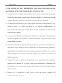
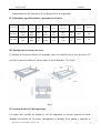
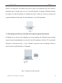
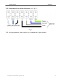
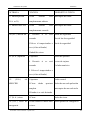
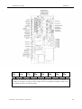
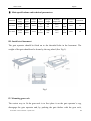
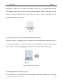
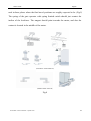
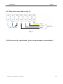
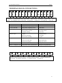
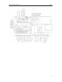
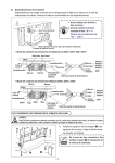
Guía de usuario
Castellano
ABRIDOR PUERTA CORREDERA
GUIA DEL USUARIO
(MODELO: SL-1800/SL-3000)
Manual instalación, conexiones y
programación.
Español
English
Tecnomatic: www.tecnomatic –systems.com
1
Guía de usuario
Castellano
I. POR FAVOR, ES MUY IMPORTANTE QUE LEA ESTAS REGLAS DE
SEGURIDAD ANTES DE COMENZAR LA INSTALACION
1. La instalación y cableado eléctrico deben de hacerse de acuerdo con las normas
locales de construcción e instalaciones eléctricas vigentes. Los cables de corriente
siempre deben de conectarse a una fuente con toma de tierra apropiada.
2. Es importante asegurarse de que la puerta puede funcionar sin impedimentos. Si la
puerta se atora o se atasca, esta debe de ser reparada inmediatamente. La
reparación siempre debe ser realizado por un técnico cualificado, no intente nunca
repararla por si mismo.
3. Los accesorios deben de guardarse lejos del alcance de los niños. No permita que
los niños jueguen con los botones o el mando a distancia. Una puerta puede causar
graves daños al cerrarse.
4. Desconectar la corriente eléctrica del sistema antes de proceder con reparaciones o
de quitar las tapas. Debe de existir un dispositivo de desconexión que garantice la
desconexión de la instalación que esta permanentemente cableado, bien a través
de un interruptor (con al menos 3mm de superficie de contacto) o mediante un
fusible específico.
5. Asegúrese de que los operarios que implicados en la instalación, mantenimiento y
operación del operador de la puerta siguen estas instrucciones. Mantenga estas
instrucciones en un sitio seguro donde pueda referirse a ellas de forma rápida si
fuera necesario.
6. Después de la instalación se debe llevar a cabo un chequeo completo del
Tecnomatic: www.tecnomatic –systems.com
2
Guía de usuario
Castellano
funcionamiento del sistema y de los dispositivos de seguridad.
II. Principales especificaciones y parámetros técnicos
Corriente
Velocidad
Torque
Articulo NO.
Peso max.
Rango de
puerta
Temperatura
Ruido
Clase
Velocidad
Certificado
eléctrica
del Motor
salida
Protección
SL-1800
AC230
/120V
1400
RPM
22N
m
12
m/min
700
KG
-45℃+65℃
≤56d
B
IP44
CE
SL-3000
AC230
/120V
1400
RPM
35N
m
12
m/min
1200
KG
-45℃+65℃
≤56d
B
IP44
CE
III. Instalación de la base de acero
El abridor de la puerta deberá ser montado sobre los tornillos de la base de acero. El
peso de la puerta no debe de recaer sobre la rueda dentada. (Ver Fig.1)
Fig.1
IV. Instalación del riel del engranaje
La forma más sencilla de montar el riel del engranaje es encajar primero la rueda
dentada del abridor de la puerta, desengranar el abridor de la puerta y empujar la
Tecnomatic: www.tecnomatic –systems.com
3
Guía de usuario
Castellano
puerta a lo largo del riel fijando este poco a poco en su posición. De esta forma se
garantiza que el acople entre el riel y la rueda dentada es óptimo. Recuerde marcar
los puntos de fijación durante la instalación (Fig.2). Debe de existir un espacio de
aproximadamente 2mm entre la rueda dentada y el riel del engranaje.
Fig. 2
V. Mecanismo para liberar el Abridor de la puerta (operación manual)
El abridor de la puerta está equipado con un mecanismo de liberación que permite
operar la puerta manualmente en caso de corte del suministro eléctrico. El mecanismo
liberador se muestra en Fig. 3 y Fig. 4 donde se aprecia como el embrague libera la
unión entre la rueda dentada y el engranaje.
Fig. 3 (LIBERACION DEL MOTOR)
Tecnomatic: www.tecnomatic –systems.com
4
Guía de usuario
Castellano
VI. Instalación de los interruptores de límite (a la puerta).
Montar los imanes o resortes localizadores de límite y sus soportes sobre el riel del
engranaje en el lugar aproximado donde debería acabar el recorrido de la puerta (Fig.
5). El resorte del abridor de la puerta que funciona con interruptores de límite de
resorte debe hacer contacto únicamente con los localizadores. Los imanes deben de
apuntar al motor y el contacto debe de situarse en la parte media del motor.
(INTERRUPTOR DE LIMITE MAGNETICO)
(INTERRUPTOR DE LIMITE DE RESORTE )
Fig. 4
Tecnomatic: www.tecnomatic –systems.com
5
Guía de usuario
Castellano
VII. Conexiones de los cables del motor (ver Fig. 5):
Fig. 5
VIII. Para programar la placa control ver el manual de la placa control.
Tecnomatic: www.tecnomatic –systems.com
6
Instalación de la placa
Castellano
PLACA DEL G-15 SISTEMA ELECTRONICA DE CONTROL DE PUERTA
INSTRUCIONES DE INSTALACION
¡IMPORTANTE!
POR FAVOR LEA TODAS LAS INSTRUCIONES ANTES DE RELIZAR
NINGUNA CONEXIÓN EN LA PLACA.
ASEGURESE QUE LA CORRIENTE DE ELECTRICIDAD 220VAC ESTA
DESONECTADA, EL INTERRUPTOR AUTOMÁTICO ESTA APAGADO Y
QUE NADIE VA A TRABAJAR EN LA RED DE SUMINISTROS ELECTRICA
DURANTE LA INSTALACION.
Conexiones Eléctricas:
El Polo Vivo se conecta a la conexión POWER L (21) en la placa.
El Polo Neutro de la fuente va a la conexión POWER N (20) en la placa.
El cable de TIERRA (22) de la fuente se conecta a la parte superior del chasis de la
unidad.
El cable común de motor debe de conectarse a la conexión COM N (17) en la placa.
El cable de bobinado en sentido de las agujas del reloj del motor debe de conectarse a
la conexión MOTOR L1 (16) de la placa.
El cable de bobinado en sentido opuesto a las agujas del reloj debe de conectarse a la
Tecnomatic: www.tecnomatic –systems.com
7
Instalación de la placa
Castellano
conexión MOTOR L2 (15) de la placa.
Los cables de la lámpara debe de conectarse a las conexión LAMP N y LP (18,19) en
la placa.
Otras Conexiones Eléctricas:
Se incluye un conector (CON4) para conectar todos los dispositivos individuales al
ordenador central de la placa. Todas las señales de entrada se conectan aquí con la
unidad de procesamiento principal mediante un cable de señal y una toma de tierra.
Más adelante se proporcionara más información.
Es posibles conectar dispositivos de salida de 18VDC al conector (CON4)
suministrado. Este puede utilizarse como fuente de alimentación para otros
dispositivos necesarios a la instalación, como los sensores.
Detección de sobrecarga:
La Placa de Control está equipada con un circuito para detectar sobrecarga, el cual
detectara la presencia de cualquier obstáculo en el recorrido de las puertas. El umbral
del sensor puede ajustarse con el potenciómetro RF2 para la apertura, y RF1para el
cierre.
La sobrecarga debe de ajustarse al umbral más alto posible que permita la operación
de las puertas sin interferencia por la fricción inherente de estas. Ajuste el
potenciómetro mediante pequeños incrementos hasta que esté satisfecho con el
funcionamiento en ambos trayectos de las puertas. Para aumentar la fuerza girar en
Tecnomatic: www.tecnomatic –systems.com
8
Instalación de la placa
Castellano
sentido de las agujas del reloj. Para disminuir la fuerza girar en sentido opuesto de las
agujas del reloj.
Temporizador del Motor:
El potenciómetro RF3 confiere un temporizador de velocidad normal, y el
potenciómetro RF4 confiere un temporizador de velocidad baja.
El temporizador cubre de 2 a 70 segundos. Girando en sentido de las agujas del reloj
aumenta el tiempo. Girando en contra del sentido de las agujas del reloj disminuye el
tiempo. Para realizar los ajustes desconecte el aparato, y espere 2 segundos. A
continuación conecte de nuevo el aparato para habilitar los cambios.
Selección de Funciones para el botón del Control Remoto:
Seleccionar el botón NO.1 hay que poner la pestaña en la posición 4 de SW2 a la
posición ON. El botón entonces seguirá el ciclo de abrir, parar y cerrar.
Seleccionar el botón NO.2 hay que poner la pestaña en posición 3 de SW2 a la
posición ON. El botón seguirá el mismo ciclo anterior.
Seleccionar el botón NO.4 hay que poner la pestaña en posición 2 de SW2 a la
posición ON. El botón hará la acción de cerrar solamente.
Seleccionar el botón NO.3 hay que poner la pestaña en posición 1de SW2 a la
posición ON. El botón hará la acción de abrir.
Selector de limite del interruptor N.C./N.A.:
La posición 4 en SW1 es el selector del interruptor de limite N.C./N.A.
Tecnomatic: www.tecnomatic –systems.com
9
Instalación de la placa
Castellano
Para seleccionar N.A. en el interruptor de límite, se debe de poner la pestaña de la
position 4 en el SW1 en posición OFF.
Para seleccionar N.C. se debe de poner la pestaña de la posición 4 en el SW1 en
posición ON.
Desconecte el equipo, espere 2 segundos y vuelva a conectarlo para habilitar los
cambios.
Selector Derecha/Izquierda:
La posición 3 en el SW1 corresponde al selector D/I
Para seleccionar la izquierda, la pestaña en la posición 3 del SW1 debe de situarse en
posición OFF.
Para seleccionar la derecha, la pestaña en la posición 3 del SW1 debe de situarse en
posición ON.
Cambiando la pestaña en la posición 3 en el SW1, se puede cambiar la dirección de
apertura y cierre. Desconecte el equipo, espere 2 segundos y vuelva a conectarlo para
habilitar los cambios.
Temporizador de cierre:
Las posiciones 1 y 2 en SW1 corresponden al temporizador de cierre automático.
Para habilitar el temporizador de cierre automático, la pestaña en la posición 1 ó 2 del
SW1, debe de situarse en posición ON. Si se selecciona la posición 1, el tiempo será
de 20 s, y si se selecciona la posición 2 el tiempo será de 10s. Si ambas posiciones 1 y
Tecnomatic: www.tecnomatic –systems.com
10
Instalación de la placa
Castellano
2 están en ON, el tiempo será de 30s.
Para desactivar el temporizador de cierre automático, ambas pestañas en las
posiciones 1 y 2 de SW1 deberán estar en posición OFF.
Desconecte el equipo, espere 2 segundos y vuelva a conectarlo para habilitar los
cambios
Aprendizaje del Control Remoto:
Apretar el botón de CODE en la placa durante un segundo y soltarlo, a continuación
apretar el botón del transmisor durante un segundo y soltarlo. El control remoto
reconoce ahora la señal.
Borrar la Información en el Control Remoto:
Mantener el botón de aprendizaje en el recibidor durante 20 segundos y soltarlo. Toda
la información en el control remoto ha sido borrada.
BLOQUE DE CONEXIONES EN EL TERMINAL
●1
●2
●3
●4
●5
●6
●7
●8
●9
●10
●11
●12
●13
1-comun 2-boton ciclo abrir/parar/cerrar/parar 3-haz de fotones 4-comun 5-boton de apertura 6-boton de cierre 7,8-parada de
emergencia 9-limite cierre 10-limite apertura 11-limite com 12,13-DC18V+ 14-DC18V-
Tecnomatic: www.tecnomatic –systems.com
11
●14
Instalación de la placa
Castellano
ENTRADA
FUNCION
DISPOSITIVO TIPICO
5-7 limite apertura
1-Para
(N.A. or N)
completamente abierta
6-7 limite cierre SW
1-Para
cuando
está Interruptor de límite
cuando
está Interruptor de límite
completamente cerrado
1-4 (N.C.) haz de luz
1-
Revertir
si
se
está Borde de seguridad
cerrando
Haz de luz de seguridad
2-Volver el temporizador a Bucle de seguridad
cero (si fue utilizado)
3-Inhabilita cierre
4-5 (N.A.) apertura
1-Apertura
2-
Botón de apertura
Revertir
si
se
está Lector de tarjetas
cerrando
Teclado numérico
3- Volver el temporizador a
cero (si fue utilizado)
1-2
(N.A.)
ABR/CRR
alt 1-Apertura
2-Cierre
Radio control
desde
apertura Botón de una sola pulsación
completa
Interruptor de una sola tecla
3-Parada si se está abriendo
1-7 (N.A.) cierre
1-Cierre
Botón de cierre
7-8 (N.C.) cierre de 1-Para cuando el motor abre Botón parada de emergencia
emergencia
o cierre.
Tecnomatic: www.tecnomatic –systems.com
12
Instalación de la placa
15●
16●
Castellano
17●
18●
19●
20●
21●
22●
15-motor de bobinado en sentido opuesto de las agujas del reloj 16-motor de bobinado en
sentido de las agujas del reloj 17-cable común motor 18,19-lampara 20-220VAC cable neutro
21-220VAC Polo Vivo 22-Toma de Tierra
Tecnomatic: www.tecnomatic –systems.com
13
User’s Guide
English
ATTENTION
Ⅰ . PLEASE START WITH READING THESE IMPORTANT SAFETY
RULES
7. Installation and wiring must be in compliance with your local building and
electrical installation codes. Power cables must only be connected to a properly
earthed supply.
8. It is important to make sure that the gate always runs smoothly. Gate which stick
or jam must be repaired immediately. Employ a qualified technician to repair the
gate, never attempt to repair it yourself.
9. Keep additional accessories away from children. Do NOT allow children to play
with pushbutton or remote controls. A gate can cause serious injuries as it closes.
10. Disconnect electric power to the system before making repairs or removing covers.
A disconnecting device must be provided in the permanently- wired installation to
guarantee all-pole disconnection by means of a switch ( at least 3mm contact gap)
or by a separate fuse.
11. Make sure that people who install, maintain or operate the gate operator follow
these instructions. Keep these instructions in a safe place so that you can refer to
them quickly when you need.
12. After the installation a final test of the full function of the system and the full
function of the safety devices must be done.
Tecnomatic: www.tecnomatic –systems.com
14
User’s Guide
English
Ⅱ. Main specifications and technical parameters
ITEM NO.
Power
supply
Motor
speed
Output
Torque
Gate
speed
Max gate
weight
Working
temperature
Noise
Protection
class
Certificate
SL-1800
AC230
/120V
1400
RPM
22Nm
12
m/min
700
KG
-45℃+65℃
≤
56dB
IP44
CE
SL-3000
AC230
/120V
1400
RPM
35Nm
12
m/min
1200
KG
-45℃+65℃
≤
56dB
IP44
CE
III. Install steel basement
The gate operator should be fitted on to the threaded bolts in the basement. The
weight of the gate should not be borne by the cog wheel (See Fig.1).
Fig.1
IV. Mounting gear rack
The easiest way to fit the gear rack is to first place it on the gate operator’s cog,
disengage the gate operator and, by pushing the gate further with the gear rack,
Tecnomatic: www.tecnomatic –systems.com
15
User’s Guide
English
screwing the rack bit by bit firmly in position. In this way, you ensure that the gear
rack engages with the cog wheel in an optimum manner. While doing this, do not
forget to mark each fixing point. (Fig.2) There is a gap of approx. 2mm between the
cog wheel and the gear rack bar.
Fig. 2
V. Gate operator release mechanism (manual operation)
The gate operator is equipped with a lockable release mechanism to enable the gate to
be operated manually in a power cut. The release mechanism is shown in Fig.3 and
Fig.4 with the clutch disengaging the link between the cog wheel and the gear.
Fig.3 (RELEASE THE MOTOR)
VI. Fitting limited switches (to gate)
Fit the localizers of spring limited switch/magnets and their brackets on to the gear
Tecnomatic: www.tecnomatic –systems.com
16
User’s Guide
English
rack in those places where the final travel positions are roughly expected to be. (Fig.5)
The spring of the gate operator with spring limited switch should just contact the
incline of the localizers. The magnet should point towards the motor, and also the
contact is located in the middle of the motor.
(MAGNETIC LIMIT SWITCH)
(SPRING LIMIT SWITCH )
Fig.4
Tecnomatic: www.tecnomatic –systems.com
17
User’s Guide
English
VII. Motor wire connection (see Fig. 5):
Fig. 5
VIII. How to set the control board - please see the manuals of control board
Tecnomatic: www.tecnomatic –systems.com
18
Control Board Installation
English
G-15 ELECTRONIC GATE SYSTEM CONTROL BOARD
INSTALLATION INSTRUCTIONS
IMPORTANT!
PLEASE READ ALL INSTRUCTIONS BEFORE BEGINNING
ANY CONNECTONS.
MAKE SURE 220VAC POWER SOURCE IS DISCONNECTED,
BREAKER IS OFF AND NO ONE IS GOING TO BE WORKING
ON THE POWER SUPPLY!
Electrical Connections:
The Hot Line from source attaches to the POWER L (21) tab on the board
The Neutral Line from source attaches to the POWER N (20) tab on the board
The EARTH PE (22) wire from source attaches top the chassis on the unit
The common wire from motor should be connected to the COM N (17) tab on the board
The clockwise rotation wire from motor should be connected to the MOTOR L1 (16) tab on the
board
The counter clockwise rotation wire from motor should be connected to the MOTOR L2 (15) tab
on the board
The lamp wire should be connected to the LAMP N and LP (18,19) tab on the board
Other Electrical Connections:
Connector (CON4) has been provided for connecting all the individual devices to the main
computer on the board all signal inputs are connected here to the main processing unit with a
signal wire and ground. More information will be provided later on.
Connector (CON4) has been made available for 18VDC auxiliary outputs. You may use these for
your other devices power needs, such as the sensors used in your particular installation.
Overload Detection:
The Control Board is equipped with an overload detection circuit, which will detect some
obstruction in the gates path.. The sensitivity is adjustable with the potentiometer labeled (RF2)
for open and labeled (RF1) for close.
The Overload must be adjusted to the most sensitive setting possible without causing self-tripping
due to the gates inherent friction. Try re-adjusting the potentiometer several times by small
increments testing the gate in both directions of travel until you are satisfied. Clockwise rotate
increase the force. Counter clockwise rotate decrease the force.
19
Control Board Installation
English
Motor run timer:
The potentiometer labeled (RF3) is for normal speed timer and labeled (RF4) for slow speed timer.
Timer is from 2 seconds to 70 seconds. Clockwise rotate increase the time. Counter clockwise
rotate decrease the time. Turn off the power, wait for a moment (2 seconds).Turn on the power to
enable the adjustment.
Remote Push Button Select:
To select NO.1 push button you must flip the rocker arm (position 4) to the ON position in the
switch (SW2). The button will cycle from open to stop and close
To select NO.2 push button you must flip the rocker arm (position 3) to the ON position in the
switch (SW2).The button will cycle too.
To select NO.4 push button you must flip the rocker arm (position 2) to the ON position in the
switch (SW2).The button is close only.
To select NO.3 push button you must flip the rocker arm (position 1) to the ON position in the
switch (SW2).The button is open only.
Limit switch N.C./N.O. Selector:
The position 4 in the switch (SW1) is limit switch N.C./N.O. selector.
Limit switch is N.O. you must flip the rocker arm (position 4) to the OFF position in the (SW1)
Limit switch is N.C. you must flip the rocker arm (position 4) to the ON position in the (SW1)
Turn off the power, wait for a moment (2 seconds) than turn on the power to enable the selection.
Left/right Hand Selector:
The position 3 in the switch (SW1) is L/R hand selector
Left hand place, you must flip the rocker arm (position 3) to the OFF position in the switch (SW1)
Right hand place, you must flip the rocker arm (position 3) to the ON position in the switch (SW1)
Change the position 3 in the switch (SW1) can change the open direction and close direction. Turn
off the power , wait for a moment (2 seconds ) than turn on the power to enable the selection.
Auto Close Timer:
(position 1 and position 2) in the switch (SW1) is use for auto close timer
To enable the auto close timer, you must flip the rocker arm (position 1or position 2) to the ON
position in the (SW1). Position 1 to on is 20 seconds. Position 2 to on is 10 seconds. Position 1
and position 2 together to on is 30 seconds.
To disable the auto close timer, you must flip the rocker arm (position 1 and position 2) to the OFF
position in the (SW1)
Turn off the power, wait for a moment (2 seconds) than turn on the power to enable the selection.
Learn The Remote:
Press the code button on the board for 1 second, release the learn button, then press the transmitter
for 1 second and release. The remote has been learned.
Erase The Remote:
Keep pressing the learn button on the receiver for 20 second, release the learn button. All remote
has been erased.
20
Control Board Installation
English
TERMINAL BLOCK CONNECTIONS
● ● ● ● ● ● ● ● ● ● ● ● ● ●
1
2
3
4
5
6
7
8
9
10 11 12 13 14
1-common 2-open/stop/close/stop cycle button 3-photo beam 4-common 5-open button 6-close
button 7,8-emergency stop 9-close limit 10-open limit 11-limit com 12,13-DC18V+ 14-DC18V-
INPUT
FUNCTION
TYPICAL DEVICES
5-7 open limit (N.O.orN
1-Stop when completely open
Limit switch
6-7 close limit SW
1-Stop when completely closed
Limit switch
3-4 (N.C.) photo beam
1-Reverse if closing
2-Reset Timer (if used)
3-Disables closing
Safe edge
Safety photo beam
Safety loop
4-5(N.O.) open
1-Open
2-Reverse if closing
3-Reset timer (if used)
Open push button
Card reader
Key pad
1-2 (N.O.) alt OPN/CLS
1-Open
2-Close from full open
3-Stop from opening
Radio control
Single push button
Single key switch
1-7(N.O.) close
1-Close
Close push button
7-8(N.C.) emergency stop
1-Stop when motor open and close
Emergency stop push button
15●
16●
17●
18●
19●
20●
21●
22●
15-motor counter clockwise rotation 16-motor clockwise rotation 17-motor common wire
18,19-lamp 20-220VAC neutral line 21-220VAC hot line 22-earth wire
21
Control Board Installation
English
22